EP1407711A1 - Système optique de mesure d'un métabolisme corporel - Google Patents
Système optique de mesure d'un métabolisme corporel Download PDFInfo
- Publication number
- EP1407711A1 EP1407711A1 EP03018933A EP03018933A EP1407711A1 EP 1407711 A1 EP1407711 A1 EP 1407711A1 EP 03018933 A EP03018933 A EP 03018933A EP 03018933 A EP03018933 A EP 03018933A EP 1407711 A1 EP1407711 A1 EP 1407711A1
- Authority
- EP
- European Patent Office
- Prior art keywords
- light receiving
- light
- array
- portions
- partial
- Prior art date
- Legal status (The legal status is an assumption and is not a legal conclusion. Google has not performed a legal analysis and makes no representation as to the accuracy of the status listed.)
- Withdrawn
Links
- 230000003287 optical effect Effects 0.000 title claims description 25
- 230000004060 metabolic process Effects 0.000 title 1
- 239000000523 sample Substances 0.000 claims abstract description 78
- QNRATNLHPGXHMA-XZHTYLCXSA-N (r)-(6-ethoxyquinolin-4-yl)-[(2s,4s,5r)-5-ethyl-1-azabicyclo[2.2.2]octan-2-yl]methanol;hydrochloride Chemical compound Cl.C([C@H]([C@H](C1)CC)C2)CN1[C@@H]2[C@H](O)C1=CC=NC2=CC=C(OCC)C=C21 QNRATNLHPGXHMA-XZHTYLCXSA-N 0.000 claims abstract description 23
- 239000013307 optical fiber Substances 0.000 claims description 37
- RKTYLMNFRDHKIL-UHFFFAOYSA-N copper;5,10,15,20-tetraphenylporphyrin-22,24-diide Chemical compound [Cu+2].C1=CC(C(=C2C=CC([N-]2)=C(C=2C=CC=CC=2)C=2C=CC(N=2)=C(C=2C=CC=CC=2)C2=CC=C3[N-]2)C=2C=CC=CC=2)=NC1=C3C1=CC=CC=C1 RKTYLMNFRDHKIL-UHFFFAOYSA-N 0.000 claims description 23
- 230000001678 irradiating effect Effects 0.000 claims description 12
- 238000003491 array Methods 0.000 claims description 11
- 230000017531 blood circulation Effects 0.000 claims description 9
- 230000008878 coupling Effects 0.000 claims description 8
- 238000010168 coupling process Methods 0.000 claims description 8
- 238000005859 coupling reaction Methods 0.000 claims description 8
- 239000002207 metabolite Substances 0.000 claims description 5
- 238000005070 sampling Methods 0.000 abstract description 18
- 210000004556 brain Anatomy 0.000 abstract description 9
- 210000003128 head Anatomy 0.000 description 38
- 238000005259 measurement Methods 0.000 description 25
- 238000012876 topography Methods 0.000 description 14
- 239000000463 material Substances 0.000 description 9
- 230000001936 parietal effect Effects 0.000 description 7
- 210000003710 cerebral cortex Anatomy 0.000 description 4
- 238000000034 method Methods 0.000 description 4
- 239000008280 blood Substances 0.000 description 3
- 210000004369 blood Anatomy 0.000 description 3
- 239000013013 elastic material Substances 0.000 description 3
- 230000000644 propagated effect Effects 0.000 description 3
- 230000000638 stimulation Effects 0.000 description 3
- 230000002123 temporal effect Effects 0.000 description 3
- 230000007177 brain activity Effects 0.000 description 2
- POIUWJQBRNEFGX-XAMSXPGMSA-N cathelicidin Chemical compound C([C@@H](C(=O)N[C@@H](CCCNC(N)=N)C(=O)N[C@@H](CCCCN)C(=O)N[C@@H](CO)C(=O)N[C@@H](CCCCN)C(=O)N[C@@H](CCC(O)=O)C(=O)N[C@@H](CCCCN)C(=O)N[C@@H]([C@@H](C)CC)C(=O)NCC(=O)N[C@@H](CCCCN)C(=O)N[C@@H](CCC(O)=O)C(=O)N[C@@H](CC=1C=CC=CC=1)C(=O)N[C@@H](CCCCN)C(=O)N[C@@H](CCCNC(N)=N)C(=O)N[C@@H]([C@@H](C)CC)C(=O)N[C@@H](C(C)C)C(=O)N[C@@H](CCC(N)=O)C(=O)N[C@@H](CCCNC(N)=N)C(=O)N[C@@H]([C@@H](C)CC)C(=O)N[C@@H](CCCCN)C(=O)N[C@@H](CC(O)=O)C(=O)N[C@@H](CC=1C=CC=CC=1)C(=O)N[C@@H](CC(C)C)C(=O)N[C@@H](CCCNC(N)=N)C(=O)N[C@@H](CC(N)=O)C(=O)N[C@@H](CC(C)C)C(=O)N[C@@H](C(C)C)C(=O)N1[C@@H](CCC1)C(=O)N[C@@H](CCCNC(N)=N)C(=O)N[C@@H]([C@@H](C)O)C(=O)N[C@@H](CCC(O)=O)C(=O)N[C@@H](CO)C(O)=O)NC(=O)[C@H](CC=1C=CC=CC=1)NC(=O)[C@H](CC(O)=O)NC(=O)CNC(=O)[C@H](CC(C)C)NC(=O)[C@@H](N)CC(C)C)C1=CC=CC=C1 POIUWJQBRNEFGX-XAMSXPGMSA-N 0.000 description 2
- 238000001514 detection method Methods 0.000 description 2
- 230000000694 effects Effects 0.000 description 2
- 230000006870 function Effects 0.000 description 2
- 230000000007 visual effect Effects 0.000 description 2
- 230000001154 acute effect Effects 0.000 description 1
- 210000005013 brain tissue Anatomy 0.000 description 1
- 229920001971 elastomer Polymers 0.000 description 1
- 238000005516 engineering process Methods 0.000 description 1
- 230000002708 enhancing effect Effects 0.000 description 1
- 230000002503 metabolic effect Effects 0.000 description 1
- 230000037023 motor activity Effects 0.000 description 1
- 230000002093 peripheral effect Effects 0.000 description 1
- 239000002504 physiological saline solution Substances 0.000 description 1
- 210000004761 scalp Anatomy 0.000 description 1
- 239000004065 semiconductor Substances 0.000 description 1
- 229920002379 silicone rubber Polymers 0.000 description 1
- 239000004945 silicone rubber Substances 0.000 description 1
- 239000007787 solid Substances 0.000 description 1
- 239000000243 solution Substances 0.000 description 1
- 238000012732 spatial analysis Methods 0.000 description 1
- 230000003068 static effect Effects 0.000 description 1
- 238000012731 temporal analysis Methods 0.000 description 1
Images


Classifications
-
- A—HUMAN NECESSITIES
- A61—MEDICAL OR VETERINARY SCIENCE; HYGIENE
- A61B—DIAGNOSIS; SURGERY; IDENTIFICATION
- A61B5/00—Measuring for diagnostic purposes; Identification of persons
- A61B5/68—Arrangements of detecting, measuring or recording means, e.g. sensors, in relation to patient
- A61B5/6801—Arrangements of detecting, measuring or recording means, e.g. sensors, in relation to patient specially adapted to be attached to or worn on the body surface
- A61B5/6813—Specially adapted to be attached to a specific body part
- A61B5/6814—Head
-
- A—HUMAN NECESSITIES
- A61—MEDICAL OR VETERINARY SCIENCE; HYGIENE
- A61B—DIAGNOSIS; SURGERY; IDENTIFICATION
- A61B5/00—Measuring for diagnostic purposes; Identification of persons
- A61B5/0059—Measuring for diagnostic purposes; Identification of persons using light, e.g. diagnosis by transillumination, diascopy, fluorescence
-
- A—HUMAN NECESSITIES
- A61—MEDICAL OR VETERINARY SCIENCE; HYGIENE
- A61B—DIAGNOSIS; SURGERY; IDENTIFICATION
- A61B5/00—Measuring for diagnostic purposes; Identification of persons
- A61B5/02—Detecting, measuring or recording pulse, heart rate, blood pressure or blood flow; Combined pulse/heart-rate/blood pressure determination; Evaluating a cardiovascular condition not otherwise provided for, e.g. using combinations of techniques provided for in this group with electrocardiography or electroauscultation; Heart catheters for measuring blood pressure
- A61B5/026—Measuring blood flow
- A61B5/0261—Measuring blood flow using optical means, e.g. infrared light
-
- A—HUMAN NECESSITIES
- A61—MEDICAL OR VETERINARY SCIENCE; HYGIENE
- A61B—DIAGNOSIS; SURGERY; IDENTIFICATION
- A61B2562/00—Details of sensors; Constructional details of sensor housings or probes; Accessories for sensors
- A61B2562/02—Details of sensors specially adapted for in-vivo measurements
- A61B2562/0233—Special features of optical sensors or probes classified in A61B5/00
-
- A—HUMAN NECESSITIES
- A61—MEDICAL OR VETERINARY SCIENCE; HYGIENE
- A61B—DIAGNOSIS; SURGERY; IDENTIFICATION
- A61B2562/00—Details of sensors; Constructional details of sensor housings or probes; Accessories for sensors
- A61B2562/04—Arrangements of multiple sensors of the same type
- A61B2562/046—Arrangements of multiple sensors of the same type in a matrix array
Definitions
- the present invention relates to an optical system for measuring, by using light, the concentration or variations in the concentration of a metabolite in a living body and more particularly, to a probe for measuring the concentration of a metabolite in a head.
- a technology which measures variations in blood volume in a cerebral cortex with brain activity at multiple points and displays the variations in blood volume as a dynamic image or a static image has already been disclosed in Medical Physics, vol. 22, No. 12 pp. 1997-2005 (1995) (Atsushi Maki, Yuichi Yamashita, Yoshitoshi Ito, Eijyu Watanabe, Yoshiaki Mayanagi, and Hideki Koizumi, "Spatial and temporal analysis of human motor activity"), and in “Non-invasive measurement of language function by using optical topography", Proceedings of SPIE, vol. 3597, pp.
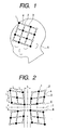
- probes in an arrangement as shown in FIG. 1 are used.
- Eight irradiated points 1 to which optical fibers for incident lights are connected and eight light receiving points 2 to which optical fibers for detecting light are connected are alternately arranged on a shell 3 configured as a tetragonal lattice with 30-mm spacings.
- Substantially middle points between the irradiated points and the light receiving points are designated as sampling points 4.
- Probes for an optical topography system having branched portions extending from a coupling shaft to fit to the configuration of a head are disclosed in Japanese Laid-Open Patent Publication No. 2001-286449.
- Probes for an optical topography system arranged in a lattice configuration which are characterized in that the coupler for the probes rotate and holders for holding the individual probes have elasticity are disclosed in Japanese Laid-Open Patent Publication No. 2002-143169.
- Probes which cover an entire head by filling a plurality of regions of the head with tetragonal lattices and filling the gaps therebetween with polygons are disclosed in Japanese Laid-Open Patent Publication No. 2002-11012.
- optical topography systems and probes described above have the following problems.
- the probes described above partially cover a head or cover the entire head by dividing the head into regions and placing a probe set on each of the regions, it has been impossible to represent the metabolic state of an entire brain as a single continuous image.
- the conventional probe arrangement configured as a tetragonal lattice it has been difficult to cover at least the upper half of a head by arranging a plurality of irradiated/light receiving point sets, while maintaining nearly uniform distances between the irradiated/light receiving points.
- the present invention has been achieved in view of the foregoing problems and it is therefore an object to the present invention to display at least the upper half of a head corresponding to a brain as a single image through close contact with the spherical head.
- a tetragonal lattice does not conform to a spherical configuration, the tetragonal lattice is obliquely deformed such that a rhombic shell is used (FIG. 2). Moreover, a plurality of rhombi are arranged to have their respective acute angles located at a parietal region such that the respective edges of the adjacent rhombi are equidistant from each other (FIGS. 3A and 3B).
- the positions of the respective irradiated/light receiving points of the adjacent rhombic shells are inverted and the distances between the respective edges of the adjacent rhombic shells are adjusted to be nearly equal to the distances between the irradiated points and the light receiving points. This allows the sampling points to be provided even between the adjacent rhombi (FIG. 2).
- FIG. 1 is a view showing a conventional arrangement of probes. Irradiated points 1 and light receiving points 2 are arranged in nearly equi-spaced relation on a shell 3 configured as a tetragonal lattice. The shell 3 is attached to the head of a subject 5.
- Light for measurement emitted from a lamp, a light-emitting diode, a semiconductor laser, or the like passes through an optical fiber for incidence to be incident on the subject 5 from each of the irradiated points 1.
- the light propagated through a cerebral cortex portion in the head of the subject 5 passes through an optical fiber for detection attached to each of the light receiving points 2 to be transmitted to a light detector such as a photodiode or a photoelectron multiplier tube and detected.
- a detect signal reflects information on blood flows throughout all the portions through which the light has been propagated, it is possible to designate substantially middle points between the irradiated points 1 and the light receiving points 2 as sampling points 4 and designate, for the sake of convenience, measured signal values as information on blood flows at the sampling points 4. From information on blood flows at a plurality of sampling points determined by the adjacent pairs of irradiated points and light receiving points, a blood flow distribution image can be obtained.
- FIG. 2 is a developed view of the arrangement of the irradiated points and light receiving points of probes according to an embodiment of the present invention.
- Four rhombic shells 3 obtained by obliquely deforming tetragonal lattices are arranged.
- the irradiated points 1 and the light receiving points 2 are arranged alternately.
- four partial arrays in each of which the irradiating portions of a light irradiator and the light receiving portions of a light detector are alternately arranged in a rhombic lattice configuration obtained by obliquely deforming a tetragonal configuration are combined to form an overall arrangement.
- the irradiated points 1 and the light receiving points 2 are arranged such that the respective positions thereof are inverted. If the probes are actually placed on a head, the edges of the shells 3 are located in superimposed relation on correction lines 6 and 8 since the head is spherical. If the distance between the shells is adjusted to substantially the same value as the length L of a line composing the rhombic lattice, the region located between the irradiated point and the light receiving point belonging to the adjacent shells can also be measured in the same manner as on the same single shell so that the sampling points 3 are formed also on the middle line 7 between the shells. Accordingly, the four 3 x 3 shells provides a 6 x 6 image of the entire head.
- the inner angles of the rhombi may be changed in accordance with the size of the head. Rhombi having small inner angles are used in the case of measuring a small head and rhombic shells having larger inner angles are used in the case of measuring a large head.
- the length of a connecting portion between the irradiated/light receiving points is not elongated, if the shells 3 are formed of an elastic material such that the apical angles of the rhombi are variable, shells capable of fitting to the head are realized.
- a material such as a silicone rubber with low elasticity may be used.
- the shells 3 may be net-like shells formed only of the coupling members indicated by the bold lines in FIG. 2 or may be sheet-like shells.
- the shells 3 may have a structure obtained by combining thin sheets and coupling members which maintain the distances between the irradiated points and the light receiving points.
- the coupling members couple optical fiber fixing sockets, the detailed structure of which will be described later.
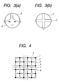
- FIGS. 3A and 3B show probes using four of the rhombic shells 3 described above which are attached to the subject 5, of which FIG. 3A is a front view of the subject and FIG. 3B shows the probes when viewed from above the parietal region of the subject.
- the apexes of the rhombic shells 3 are disposed to surround the parietal region so that the shells 3 are located on the left and right frontal regions and on the left and right occipital regions. If the distances between the shells are held nearly uniform, the apex portions may also be disposed to surround a portion other than the parietal region.
- the shells may also be disposed at the frontal region, the right temporal region, the left temporal region, and the occiptal region. It will easily be appreciated that the shells may be disposed at any positions provided that the distance between the shells are held nearly uniform.
- an image is displayed as it is in a developed view of rhombi as shown in FIG. 2, the image is hard to be viewed as a plan image so that correction is made to provide an arrangement as shown in FIG. 4. If the correction is made to change the rhombi into a tetragonal lattice, the tetragonal lattices are arranged along the correction lines 6 and 8 in a plane so that the entire head is displayed as a single plan image.
- FIG. 5 shows an example of the display of an image thus corrected.
- An image 9 obtained by making correction to change the rhombi into the tetragonal lattice, connecting the plurality of sampling points 4 through correction to each other, and performing interpolation therebetween is disposed in superimposing relation on a head image 10 that has been corrected similarly and deformed. Since the head image has also been corrected and deformed similarly to the irradiated/light receiving points, positions with signal changes on a measurement image can more easily be associated with the positions on the head. As the image disposed in superimposing relation on the measurement image, a developed view of a brain that has been corrected similarly may also be used. Besides the correction method which changes the rhombi into the tetragonal lattice, correction may also be made in an easy-to-view form. It will easily be appreciated that 3D display may also be performed without making correction.
- FIG. 6 shows another embodiment of the arrangement of probes.
- a 8 x 8 image is obtainable by using four 4 x 4 shells.
- the number of the shells need not necessarily be 4. However, it is necessary to use an even number of shells to measure each of the regions located between the shells.
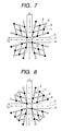
- FIG. 7 shows still another embodiment of the arrangement of probes.
- Measurement is basically for obtaining a 8 x 8 image by using four 4 x 4 shells but five irradiated/light receiving points arranged, i.e., these points in the vicinity of the eyes and the neck are removed from each of the shells.
- an optical fiber is not connected to each of the five points.
- FIG. 8 also shows an embodiment of the arrangement of probes.
- measurement is for obtaining a 8 x 8 image by using four 4 x 4 shells but six irradiated/light receiving points are removed from each of the shells.
- FIG. 9 shows the case where the probes in the arrangement of FIG. 7 are attached to the head of the subject 5. Since the irradiated/light receiving points in the vicinity of the eyes are removed, safe measurement is performed. In the description given thus far, probes are formed by arranging four rhombic shells on the head of the subject. In an actual situation, however, finished probes need not necessarily have a structure that can be decomposed into the shells. Although the coupling members are depicted to exist only within each of the shells in the developed views of FIGS. 2, 6, and 7, this is for easy understanding of the structure. As shown in FIG. 9, the shells have been coupled from the beginning with similar coupling members in the finished probes. It is to be noted that the subsequent developed views also have similar omission.
- FIG. 10 shows still another embodiment of the arrangement of probes.
- the individual shells 3 are not arranged in mutually spaced apart relation but are arranged such that the respective irradiated points and respective light receiving points of the adjacent shells are in overlapping relation.
- one irradiation point and one light receiving point serve as the respective irradiated points and light receiving points of the adjacent two shells.
- the irradiated point 1 indicated by the solid circle in FIG. 10 also serves as the overlapping irradiated point 11 indicated by the dotted circle on the adjacent shell.
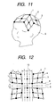
- FIG. 11 shows an example of the attachment of the probes in the arrangement of FIG. 10.
- the irradiated points and light receiving points of the adjacent shells are shared.
- FIG. 12 shows yet another embodiment of the arrangement of probes.
- the distance between adjacent shells is adjusted to 2L and irradiated points 1 and light receiving points 2 are aligned on a substantially middle line 13 between the adjacent shells.
- a structure in which rhombic shells on the left and right hands are coupled with a shell in a tetragonal arrangement is formed.
- the arrangement is suitable for use on a subject having a head which is oblong in a front-to-rear direction. Since the density of sampling points 3 is higher in the vicinity of the parietal region, the effect of increased resolution in the vicinity of the parietal region is also achieved.
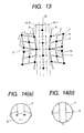
- FIG. 13 shows another embodiment of the arrangement in which irradiated points and light receiving points are aligned on a line 13 located between the adjacent shells, similarly to FIG. 12.
- the arrangement of shells is more fittable to a head which is oblong in the front-to-rear direction.
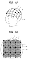
- FIGS. 14A and 14B show the arrangement of the shells when probes in the arrangement of FIG. 13 are attached to a subject, of which FIG. 14A is a front view of the subject and FIG. 14B shows the probes when viewed from above the parietal region of the subject.
- the rhombic shells 3 are attached to be positioned on the temporal region of the subject 5.
- FIG. 15 is a view similarly showing the probes in the arrangement of FIG. 13 when they are attached to a subject.
- FIG. 16 is a view showing data obtained from measurement performed by using the probes in the arrangement of FIG. 6, which has been corrected as shown in FIG. 4 and displayed as an image.
- a head image 10 superimposed on a measurement image 9 is not a corrected image and a simplified head image is used.
- Sampling points 3 between irradiated points 1 and light receiving points 2 are arranged with about 21-mm spacings when the irradiation-to-detection distance is 30 mm.
- the measurement image 9 is an octagonal image occupying an area smaller than that of the shell 3. If there is a sampling point at which a quality signal could not be obtained by trouble or the like, it is possible to estimate the value at the sampling point at which the signal could not be obtained by using peripheral sampling points and thereby interpolate the image.
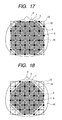
- FIG. 17 shows a measurement image obtained as a result of making correction similar to that shown in FIG. 16 when one of the irradiation and light receiving points on each of the rhombic shells 3 is removed. Since sampling points 16 cannot be obtained around the removed points 15, the measurement image 9 has a configuration as shown in FIG. 17.
- FIG. 18 shows a measurement image obtained as a result of making correction similar to that shown in FIG. 16 when three of the irradiation and light receiving points on each of the rhombic shells 3 are removed.
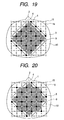
- FIG. 19 shows a measurement image obtained as a result of making correction similar to that shown in FIG. 16 when six of the irradiation and light receiving points on each of the rhombic shells 3 are removed, i.e., when the probes in the arrangement of FIG. 8 are used.
- FIG. 20 shows a measurement image obtained as a result of making correction similar to that shown in FIG. 16 when five of the irradiation and light receiving points on each of the rhombic shells 3 are removed, i.e., when the probes in the arrangement of FIG. 7 are used.
- FIGS. 21A to 21C show an embodiment of a method for probe fixation when the probes according to the present invention are attached to a subject, of which FIG. 21A is a front view of the subject, FIG. 21B is a rear view thereof, and FIG. 21C is a side view thereof.
- Optical fiber fixing sockets 17 connected to the irradiated/light receiving points are attached onto the shells 3 such that optical fibers fitted in the optical fiber fixing sockets 17 are fixed thereby.
- the head of the subject is covered with a fixing cap 18 from over the optical fiber fixing sockets such that the probes as a whole do not fall down from the head.
- the cap 18 has strings which are tied under the chin, armpit, or the like for the fixation of the probes.
- a pillow 19 may be placed appropriately near the neck of the subject to keep the head of the subject in a raised state and prevent a load on the fixing sockets 17. In this case, the pillow 19 has been attached to the cap but it may also be placed on a recumbent bed or fixed to the bed.
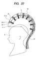
- FIG. 22 shows another embodiment of the method for probe fixation when the probes according to the present invention are attached to a subject.
- the probes are fixed in a helmet 20 and the subject wears the helmet 20 when measurement is performed.
- the lower parts 17-1 of optical fiber fixing sockets are attached to the shells 3 and optical fiber tip portions 21 are inserted therein.
- the lower parts 17-1 of optical fiber fixing sockets are internally provided with springs 22-1 such that the optical fiber tip portions 21 are vertically movable. Accordingly, the optical fiber tip portions 21 retract when the subject 5 puts on the helmet 20 so that they are less likely to cause pain in the subject 5.
- the lower parts 17-1 of optical fiber fixing sockets are inserted in upper parts 17-2 of optical fiber fixing sockets which are fixed in the helmet 20 so that the lower parts 17-1 of optical fiber fixing sockets are vertically movable with springs 22-2 provided in the upper parts 17-2 of the optical fiber fixing sockets. Since the shells 3 are deformed in conformity with the configuration of the head of the subject 5, the effects of enhancing the fittability of the shells to the head and reducing the probability of causing pain are achieved.
- the springs 22-1 or 22-2 another material or instrument functioning as a cushioning material or an elastic material or instrument may also be used. In that case, the upper parts 17-2 of optical fiber fixing sockets need not be used. Alternatively, the lower parts 17-1 of optical fiber fixing sockets need not be used.
- Optical fibers 23 extend from the optical fiber tip portions 21 through the space between the shells 3 and the helmet 20 to be extracted collectively from the end of the helmet 20 in the vicinity of the neck to the outside. Besides extracting the optical fibers 23 from the end of the helmet 20 to the outside, it is also possible to form a single or plurality of holes in a specified portion of the helmet and extract the optical fibers 23 therefrom to the outside.
- the space between the shells 3 and the helmet 20 may be hollow or filled with a cushioning material such as a gel, sponge, or the like. In that case, a path allowing the passage of the optical fibers 23 is provided.
- the portions of the lower parts 17-1 of optical fiber fixing sockets which come in contact with the head may also be lined with a sponge or a gel-like cushioning material. This reduces stimulation to the scalp. It is also possible to impart conductivity to a cushioning material by impregnating sponge with a physiological saline or using a conductive gel material, connect electric lines to the cushioning material, and thereby use the conductive cushioning material as electrodes for electrical brain wave measurement. This allows optical measurement and electrical brain wave measurement to be performed simultaneously. Alternatively, the sockets and the electrodes may be disposed separately such that the electrodes for electrical brain wave measurement are positioned between the sockets.
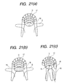
- FIGS. 23A and 23B show a variation of probes configured as a helmet shown in FIG. 22.
- the helmet is composed of two structures of a helmet front part 20-2 and a helmet rear part 20-1 shown in FIG. 23A, which are connected to each other with hinges to be switchable between open and closed states.
- the probes are similarly constructed to those shown in FIG. 22 in that they have shells to which optical fibers are attached within each of the structures and the optical fibers and the shells are outwardly press-expandable in accordance with the size and configuration of the head.
- the probes are put on the subject 5 with the helmet front part 20-2 and the helmet rear part 20-1 shown in FIG. 23B being in the open state and worn by subsequently closing the helmet front part 20-2.
- a monitor 24 configured as a sun visor or a pair of goggles to the helmet front part 20-2.
- the monitor 24 is used when brain activity is optically measured while visual information or visual stimulation is given to the subject.
- an earphone 25 to the helmet and perform measurement while giving audio information or auditory stimulation to the subject.
- the present variation allows easy wearing of the helmet by a subject who cannot put on the helmet by himself or herself, such as a new-born.
- the helmet may be divided not only into the front and rear parts but also into left and right parts or into three parts including a rear part, a front right part, and a front left part.
- the helmet may also be divided into three or more parts.
- an integral-type helmet to be press-expandably put on, not a helmet divided in parts may also be used.
- FIG. 24 shows the case where measurement is performed with a subject wearing the helmet-type probes shown in FIG. 22, FIG. 23A, or FIG. 23B in a recumbent posture.
- the helmet 20 is fixed onto a bed 26 or placed thereon.
- a pillow 19 is fixed to the bed or to the helmet or placed on the bed 26.
- Optical fibers 23 extend through the bed 26 to be extracted to the outside such that they are prevented from being tucked under the subject 5.
- the optical fibers 23 are also allowed to extend through the pillow 19. This prevents the optical fibers from being tucked under the subject 5 or obstructing measurement.
- the helmet may also be painted with a comfortable color, pattern, picture, or the like which relieves the tension of the subject or configured as a character such as an animal provided that it retains the function of probes.
Applications Claiming Priority (2)
| Application Number | Priority Date | Filing Date | Title |
|---|---|---|---|
| JP2002293153 | 2002-10-07 | ||
| JP2002293153A JP2004121702A (ja) | 2002-10-07 | 2002-10-07 | 生体光計測装置 |
Publications (1)
| Publication Number | Publication Date |
|---|---|
| EP1407711A1 true EP1407711A1 (fr) | 2004-04-14 |
Family
ID=32025472
Family Applications (1)
| Application Number | Title | Priority Date | Filing Date |
|---|---|---|---|
| EP03018933A Withdrawn EP1407711A1 (fr) | 2002-10-07 | 2003-08-20 | Système optique de mesure d'un métabolisme corporel |
Country Status (3)
| Country | Link |
|---|---|
| US (1) | US6904302B2 (fr) |
| EP (1) | EP1407711A1 (fr) |
| JP (1) | JP2004121702A (fr) |
Cited By (4)
| Publication number | Priority date | Publication date | Assignee | Title |
|---|---|---|---|---|
| US6904302B2 (en) | 2002-10-07 | 2005-06-07 | Hitachi, Ltd. | Optical system for measuring metabolism in a body |
| EP1665979A1 (fr) * | 2004-12-03 | 2006-06-07 | Hitachi, Ltd. | Système optique pour mesurer des propriétés tissulaires |
| EP1949848A1 (fr) * | 2007-01-25 | 2008-07-30 | Hitachi, Ltd. | Instrument de mesure optique pour un corps vivant |
| EP2027813A1 (fr) * | 2007-08-21 | 2009-02-25 | Hitachi Ltd. | Support à couplage de tête pour la mesure optique d'un corps vivant |
Families Citing this family (12)
| Publication number | Priority date | Publication date | Assignee | Title |
|---|---|---|---|---|
| JP4489385B2 (ja) * | 2002-12-12 | 2010-06-23 | 株式会社日立メディコ | 計測プローブ及び生体光計測装置 |
| JP4636166B2 (ja) * | 2003-04-02 | 2011-02-23 | 株式会社島津製作所 | 光生体測定装置及びホルダー |
| JP2006223503A (ja) * | 2005-02-17 | 2006-08-31 | Shimadzu Corp | ホルダーおよびこれを用いた複合生体測定装置 |
| US7747301B2 (en) * | 2005-03-30 | 2010-06-29 | Skyline Biomedical, Inc. | Apparatus and method for non-invasive and minimally-invasive sensing of parameters relating to blood |
| JPWO2007135993A1 (ja) * | 2006-05-23 | 2009-10-01 | 株式会社日立メディコ | 生体光計測装置 |
| US8457705B2 (en) * | 2006-10-25 | 2013-06-04 | University Of Denver | Brain imaging system and methods for direct prosthesis control |
| US10226206B2 (en) * | 2007-04-11 | 2019-03-12 | The Board Of Regents Of The University Of Texas System | Systems and methods for measuring neonatal cerebral oxygenation |
| JP5481032B2 (ja) * | 2008-02-20 | 2014-04-23 | 株式会社日立製作所 | 生体光計測用プローブ及びそれを用いた生体光計測装置 |
| US8583565B2 (en) * | 2009-08-03 | 2013-11-12 | Colorado Seminary, Which Owns And Operates The University Of Denver | Brain imaging system and methods for direct prosthesis control |
| US20130085398A1 (en) | 2011-09-26 | 2013-04-04 | California Institute Of Technology | Brain-machine interface based on photonic neural probe arrays |
| WO2014076774A1 (fr) * | 2012-11-14 | 2014-05-22 | 株式会社島津製作所 | Dispositif biométrique optique et dispositif de mesure de position l'utilisant |
| AU2016233575A1 (en) | 2015-03-14 | 2017-07-13 | The Board Of Regents Of The University Of Texas System | Systems and methods for measuring neonatal cerebral oxygenation |
Citations (4)
| Publication number | Priority date | Publication date | Assignee | Title |
|---|---|---|---|---|
| WO1999040841A1 (fr) * | 1998-02-11 | 1999-08-19 | Non-Invasive Technology, Inc. | Visualisation et caracterisation du tissu cerebral |
| JP2001286449A (ja) | 2000-04-10 | 2001-10-16 | Hitachi Medical Corp | プローブ装置 |
| JP2002011012A (ja) | 2000-06-29 | 2002-01-15 | Hitachi Ltd | 生体光計測装置及び生体光計測用固定具 |
| JP2002143169A (ja) | 2000-11-07 | 2002-05-21 | Hitachi Ltd | 光計測装置、および光ファイバー保持装置 |
Family Cites Families (4)
| Publication number | Priority date | Publication date | Assignee | Title |
|---|---|---|---|---|
| US5853370A (en) * | 1996-09-13 | 1998-12-29 | Non-Invasive Technology, Inc. | Optical system and method for non-invasive imaging of biological tissue |
| US5803909A (en) * | 1994-10-06 | 1998-09-08 | Hitachi, Ltd. | Optical system for measuring metabolism in a body and imaging method |
| JP4055266B2 (ja) * | 1998-10-13 | 2008-03-05 | 株式会社日立製作所 | 光計測装置 |
| JP2004121702A (ja) | 2002-10-07 | 2004-04-22 | Hitachi Ltd | 生体光計測装置 |
-
2002
- 2002-10-07 JP JP2002293153A patent/JP2004121702A/ja active Pending
-
2003
- 2003-08-13 US US10/639,439 patent/US6904302B2/en not_active Expired - Fee Related
- 2003-08-20 EP EP03018933A patent/EP1407711A1/fr not_active Withdrawn
Patent Citations (5)
| Publication number | Priority date | Publication date | Assignee | Title |
|---|---|---|---|---|
| WO1999040841A1 (fr) * | 1998-02-11 | 1999-08-19 | Non-Invasive Technology, Inc. | Visualisation et caracterisation du tissu cerebral |
| JP2002502653A (ja) | 1998-02-11 | 2002-01-29 | ノン−インヴェイシヴ テクノロジイ,インク. | 脳組織の画像形成および特徴表示 |
| JP2001286449A (ja) | 2000-04-10 | 2001-10-16 | Hitachi Medical Corp | プローブ装置 |
| JP2002011012A (ja) | 2000-06-29 | 2002-01-15 | Hitachi Ltd | 生体光計測装置及び生体光計測用固定具 |
| JP2002143169A (ja) | 2000-11-07 | 2002-05-21 | Hitachi Ltd | 光計測装置、および光ファイバー保持装置 |
Non-Patent Citations (3)
| Title |
|---|
| PATENT ABSTRACTS OF JAPAN vol. 2002, no. 02 2 April 2002 (2002-04-02) * |
| PATENT ABSTRACTS OF JAPAN vol. 2002, no. 05 3 May 2002 (2002-05-03) * |
| PATENT ABSTRACTS OF JAPAN vol. 2002, no. 09 4 September 2002 (2002-09-04) * |
Cited By (8)
| Publication number | Priority date | Publication date | Assignee | Title |
|---|---|---|---|---|
| US6904302B2 (en) | 2002-10-07 | 2005-06-07 | Hitachi, Ltd. | Optical system for measuring metabolism in a body |
| EP1665979A1 (fr) * | 2004-12-03 | 2006-06-07 | Hitachi, Ltd. | Système optique pour mesurer des propriétés tissulaires |
| US7231241B2 (en) | 2004-12-03 | 2007-06-12 | Hitachi, Ltd. | Probe for optical measurement instrument for living body and optical measurement instrument for living body using the same |
| EP1949848A1 (fr) * | 2007-01-25 | 2008-07-30 | Hitachi, Ltd. | Instrument de mesure optique pour un corps vivant |
| US8244324B2 (en) | 2007-01-25 | 2012-08-14 | Hitachi, Ltd. | Optical measurement instrument for living body |
| EP2027813A1 (fr) * | 2007-08-21 | 2009-02-25 | Hitachi Ltd. | Support à couplage de tête pour la mesure optique d'un corps vivant |
| CN101371780B (zh) * | 2007-08-21 | 2010-12-15 | 株式会社日立制作所 | 生物体光计测用头部安装式固定器 |
| US8103332B2 (en) | 2007-08-21 | 2012-01-24 | Hitachi, Ltd. | Head-coupled holder for living body optical measurement |
Also Published As
| Publication number | Publication date |
|---|---|
| US6904302B2 (en) | 2005-06-07 |
| JP2004121702A (ja) | 2004-04-22 |
| US20040077935A1 (en) | 2004-04-22 |
Similar Documents
| Publication | Publication Date | Title |
|---|---|---|
| US6904302B2 (en) | Optical system for measuring metabolism in a body | |
| US6618614B1 (en) | Optical examination device, system and method | |
| EP0906052B1 (fr) | Coupleur optique pour un dispositif d'examen optique | |
| JP4283467B2 (ja) | 生体計測用プローブ及びそれを用いた生体光計測装置 | |
| US20100249608A1 (en) | Optical examination device, system and method | |
| Shibata et al. | Generators of visual evoked potentials for faces and eyes in the human brain as determined by dipole localization | |
| Johnson et al. | Recording and analyzing high-density event-related potentials with infants using the Geodesic Sensor Net | |
| US6397099B1 (en) | Non-invasive imaging of biological tissue | |
| US5291888A (en) | Head sensor positioning network | |
| CA2623384C (fr) | Reseau d'electrodes | |
| Opsommer et al. | Dipole analysis of ultralate (C-fibres) evoked potentials after laser stimulation of tiny cutaneous surface areas in humans | |
| WO2021167890A1 (fr) | Ensemble module pouvant être portés pour un système de mesure optique | |
| WO1998010698A9 (fr) | Imagerie non vulnerante de tissu biologique | |
| WO1998010698A1 (fr) | Imagerie non vulnerante de tissu biologique | |
| ES2752600T3 (es) | Dispositivo para grabar video-electroencefalogramas | |
| JPWO2006009178A1 (ja) | 生体機能診断装置、生体機能診断方法、生体用プローブ、生体用プローブ装着具、生体用プローブ支持具及び生体用プローブ装着支援具 | |
| JP2010535542A (ja) | 前庭刺激装置および関連する使用の方法 | |
| CN107468241A (zh) | 脑电帽 | |
| JP5481032B2 (ja) | 生体光計測用プローブ及びそれを用いた生体光計測装置 | |
| Nevalainen et al. | Trigeminal somatosensory evoked magnetic fields to tactile stimulation | |
| US20040064052A1 (en) | Non-invasive imaging of biological tissue | |
| Weiland et al. | Evidence for a frontal cortex role in both auditory and somatosensory habituation: a MEG study | |
| Papadelis et al. | Current and emerging potential for magnetoencephalography in pediatric epilepsy | |
| US7231241B2 (en) | Probe for optical measurement instrument for living body and optical measurement instrument for living body using the same | |
| JP4961442B2 (ja) | 生体計測用プローブ及び生体光計測装置 |
Legal Events
| Date | Code | Title | Description |
|---|---|---|---|
| PUAI | Public reference made under article 153(3) epc to a published international application that has entered the european phase |
Free format text: ORIGINAL CODE: 0009012 |
|
| AK | Designated contracting states |
Kind code of ref document: A1 Designated state(s): AT BE BG CH CY CZ DE DK EE ES FI FR GB GR HU IE IT LI LU MC NL PT RO SE SI SK TR |
|
| AX | Request for extension of the european patent |
Extension state: AL LT LV MK |
|
| 17P | Request for examination filed |
Effective date: 20041005 |
|
| AKX | Designation fees paid |
Designated state(s): DE GB |
|
| 17Q | First examination report despatched |
Effective date: 20050126 |
|
| STAA | Information on the status of an ep patent application or granted ep patent |
Free format text: STATUS: THE APPLICATION IS DEEMED TO BE WITHDRAWN |
|
| 18D | Application deemed to be withdrawn |
Effective date: 20051126 |