EP1407214B1 - Vorrichtung und dazugehöriges verfahren zum bestimmen der richtung eines zieles - Google Patents
Vorrichtung und dazugehöriges verfahren zum bestimmen der richtung eines zieles Download PDFInfo
- Publication number
- EP1407214B1 EP1407214B1 EP02738206A EP02738206A EP1407214B1 EP 1407214 B1 EP1407214 B1 EP 1407214B1 EP 02738206 A EP02738206 A EP 02738206A EP 02738206 A EP02738206 A EP 02738206A EP 1407214 B1 EP1407214 B1 EP 1407214B1
- Authority
- EP
- European Patent Office
- Prior art keywords
- sighting
- processing
- sensor
- gyrometers
- processing means
- Prior art date
- Legal status (The legal status is an assumption and is not a legal conclusion. Google has not performed a legal analysis and makes no representation as to the accuracy of the status listed.)
- Expired - Lifetime
Links
Images

Classifications
-
- F—MECHANICAL ENGINEERING; LIGHTING; HEATING; WEAPONS; BLASTING
- F41—WEAPONS
- F41G—WEAPON SIGHTS; AIMING
- F41G3/00—Aiming or laying means
- F41G3/06—Aiming or laying means with rangefinder
-
- F—MECHANICAL ENGINEERING; LIGHTING; HEATING; WEAPONS; BLASTING
- F41—WEAPONS
- F41G—WEAPON SIGHTS; AIMING
- F41G3/00—Aiming or laying means
- F41G3/02—Aiming or laying means using an independent line of sight
-
- G—PHYSICS
- G01—MEASURING; TESTING
- G01C—MEASURING DISTANCES, LEVELS OR BEARINGS; SURVEYING; NAVIGATION; GYROSCOPIC INSTRUMENTS; PHOTOGRAMMETRY OR VIDEOGRAMMETRY
- G01C21/00—Navigation; Navigational instruments not provided for in groups G01C1/00 - G01C19/00
- G01C21/10—Navigation; Navigational instruments not provided for in groups G01C1/00 - G01C19/00 by using measurements of speed or acceleration
- G01C21/12—Navigation; Navigational instruments not provided for in groups G01C1/00 - G01C19/00 by using measurements of speed or acceleration executed aboard the object being navigated; Dead reckoning
- G01C21/16—Navigation; Navigational instruments not provided for in groups G01C1/00 - G01C19/00 by using measurements of speed or acceleration executed aboard the object being navigated; Dead reckoning by integrating acceleration or speed, i.e. inertial navigation
- G01C21/183—Compensation of inertial measurements, e.g. for temperature effects
Definitions
- the present invention relates to the field of sighting devices or pointing. It more particularly relates to a mobile device capable of determining position, kinematic and identification elements of a target in a predefined or geographical marker, device of the type comprising sighting means and signal processing means from sighting means. These processing means being able to determine position, kinematic and identification elements of the target and to transmit them to external means.
- Such devices exist and implement magnetic field sensors.
- binoculars sold under the brand name LEICA, which use magnetic sensors and an active rangefinder, are able to determine the site and azimuth of a target and are satisfactory when used in free space.
- LEICA which use magnetic sensors and an active rangefinder
- their use suffers from certain prohibitive limitations for specific uses: they are not usable in an environment involving magnetic disturbances and, on the other hand, the speed and precision of the measurements are very limited.
- Other devices consist of analyzing electrostatic or even electromagnetic fields and, by surveying their mapping, to determine the position and direction of a target.
- the devices are satisfactory in perfectly known environments and small dimensions. They are however heavy to implement and do not support changes in the electrical environment.
- the patent is known US4012989 which describes a helicopter having a device for determining the direction of a target for directing a mobile weapon system.
- the device for determining the direction of a target comprises a movable sighting member provided with two integrated inertial gyroscopes, integral resetting means of the helicopter provided with two gyroscopes and means for controlling the direction of the weapon. according to the information provided by the gyroscopes.
- the resetting means serve to block the four gyroscopes in a first reference position to define a marker. When the sighting means are disengaged from the resetting means, the four gyroscopes are released.
- the pair of gyroscopes integrated in the resetting means then rotates according to the movements of the helicopter.
- the pair of gyroscopes integrated into the sighting unit rotates according to the movements of the helicopter and the movements of the shooter operating the sighting device.
- the weapon is directed, in real time, towards the target according to the difference in rotation between the two pairs of gyroscopes.
- This device has many disadvantages.
- the shooter is obliged to maintain the means of sight permanently towards the target, and until the firing of the weapon system which limits the shooting capabilities and makes the helicopter vulnerable in case of presence of several targets.
- the two gyroscopes of the aiming means transmit to the processing means successions of signal variations causing an accumulation of measurement errors which is detrimental to the accuracy of the determination of the direction of the target.
- the orientation of the weapon system towards the target would be almost impossible with such a device.
- the document FR 2536936 describes a horizon generator circuit, for generating a video signal intended to represent the horizon in the image generation devices used, in particular, in simulated target simulated gun training simulators.
- the simulator includes various elements mounted on the barrel including motion sensors composed of a gyrometer and two inclinometers that track the movement of the barrel.
- This device does not provide any element contributing to the determination of the position of a target in a real environment.
- the document EP 0484202 describes a system for aligning the inertial unit of a vehicle with that of a carrier vehicle. It concerns the registration of an inertial unit relative to a second inertial unit that is mechanically interdependent.
- the object of the invention is to provide a lightweight and manageable device, able to determine, precisely and quickly, the site and the azimuth of a target and usable whatever the type of environment.
- the document WO 98/31985 discloses a device adapted to determine the direction of a target in a predefined frame according to the preamble of claim 1.
- This device requires physical registration means which are very often difficult to implement and which constitute a major drawback for certain applications.
- the proposed solution is a device capable of determining the direction of a target in a predefined frame according to claim 1.
- said at least one sensor is constituted by a two-axis inclinometer or by at least two inclinometers.
- said at least one sensor is constituted by a multi-axis accelerometer or by at least two accelerometers.
- said at least one sensor is constituted by an electronic image sensor.
- the electronic sensor image is able to generate a signal representative of images and which is transmitted to processing means of this signal able to determine the position of a pattern in said images.
- the sighting elements comprise an electronic image sensor and associated image processing means making it possible to compensate for the "shake" of the operator, such as for example an image stabilizer.
- the means for processing the sighting means are able to compensate the movement of the operator from the value of the optical field of the electronic image sensor.
- the means for processing the sighting means are able to determine the angular field of the electronic image sensor from the relationship between the camera shake from the signal of the electronic sensor and that of the sighting means.
- the means for processing the sighting means are capable of contributing to the transmission of identification elements of the target and / or to the detection of the absolute direction of the aiming means and possibly to generating, from the signals of the target electronic sensor of images and sighting means, a signed image that is to say comprising information of position in space and in time (time stamp, geographical position, attitude, distance from the point of view ...
- These processing means can also, from the signed images, reconstitute the global landscape with the position information for different zones of the latter.
- These images and / or the reconstituted landscape can then be transmitted to visualization means or means. exteriors.
- the device comprises means for recording the signal coming from the electronic image sensor, and / or that it comprises means for viewing said images as well as certain information such as the direction of the targeted target, its distance and / or its nature.
- said at least one sensor consists of at least two magnetic receivers.
- a magnetic transmitter can be associated with the latter.
- a device according to the invention comprises three optical gyrometers, for example optical fiber.
- the aiming means comprise the acquisition of the geographical position by radio positioning means, for example satellite GPS, and may comprise an active rangefinder.
- the sighting means comprise at least two accelerometers and in that the processing means comprise triangulation means capable of performing discrete telemetry.
- the sighting means comprise at least one magnetic sensor used to compensate for errors depending on the magnetic field of the gyrometers used and / or to make it possible to correlate the measurements with respect to the terrestrial magnetic field.
- the sighting means comprise at least one accelerometer used to compensate for errors according to the accelerations of the gyrometers used and / or to allow the calculation of the displacement of the aiming means.
- the sighting means comprise at least one inclinometer used to calculate the inclination of the aiming means relative to to the Earth's gravitational field and / or correlate measurements.
- the sighting means comprise wireless transmission means for removing the cables between the different means.
- the processing means comprise telecommunications means intended in particular for conveying the acquired information to an operations center.
- the sighting means comprise an active rangefinder.
- the sighting means comprise an active laser-type rangefinder.
- the processing means comprise triangulation means for performing discrete telemetry, this static triangulation being able to execute from several aiming stations.
- the processing means comprise triangulation means for performing discrete telemetry, this dynamic triangulation being able to execute from a single viewing station moving according to a known kinematics.
- part of the acquisition means of the sighting means can be transferred to another location for example for reasons of weight or ergonomics.
- the sighting means comprise at least one temperature sensor used to compensate for errors depending on the temperature of the gyrometers used.
- the first concerns the correction of gyro biases on one aircraft and the second on a vehicle. In both cases, the gyroscopic calibration is performed when the aircraft or vehicle is stationary.
- One of the aims of the invention is to propose a method of processing signals from gyroscopes giving good results and not requiring powerful signal processing means or mechanical resetting means.
- the solution is a registration method according to claim 25.
- said second marker is a terrestrial marker, or a geographical marker relative to a magnetic transmitter or a geographical marker with respect to a pattern whose position does not vary or very little.
- it comprises a step of determining on the one hand the direction of a line D1 parallel to the axis of rotation of the earth and passing through the point P where the aiming means 10 are located from the signals from the gyroscopes and secondly from the direction of the vertical D2 at the point P of the place from the two signals from said sensor.
- it comprises a complementary step of determining the direction of the geographical north, this direction being obtained by the intersection of the plane defined by the straight lines D1 and D2 with the plane perpendicular to
- the sighting means comprise at least three sensors, namely three magnetic receivers
- the device comprises a magnetic transmitter
- the processing means calculate the position and the orientation, namely the attitude, the aiming means from the signals from the magnetic sensors and the expected mapping of the magnetic field that has been previously introduced into memory in these processing means .
- the sighting means comprise an electronic image sensor, such as a camera rigidly fixed to the sighting means
- this camera generates a signal representative of the image observed, characterized in that it comprises a step in which the image processing means are able to determine the position of a pattern in said image, the position of this pattern being known.
- the solution is also a method of resetting a device capable of determining the direction of a target in a first predetermined reference frame and of the type comprising sighting means, comprising a sighting device, three gyrometers arranged along three non-coplanar axes, control means, and means for processing signals from the aiming means, these processing means being able to determine the direction between the aiming means and the target, characterized in that it comprises a step in which the processing means determine the value of the gravity vector either continuously or at several times T 0 , T 1 ..T i ... T n , from the signal coming from at least one non-gyro sensor disposed on the means of aiming.
- This second step may further comprise the calculation of the latitude of the point P where the means of sighting on land are located.
- the solution also possibly consists in proposing a method for integrating the gyroscopic data consisting in successively performing from the gyro values obtained between a time to and a time t1, initial calculations with complex modeling can not, given the processing capacity of the processing means, operate in real time but give accurate results, and then from the gyro values obtained between time t1 and time t2, second calculations with simplified modeling and capable of being implemented in real time.
- the software also performs a function of correcting the drift of the gyrometers by modeling their long-term drift between successive measurements.
- the software also performs a function of correcting the drift of the gyrometers by modeling the magnetic field between successive measurements.
- the software also performs an automatic calibration function consisting in correcting the drift of the gyrometers by modeling their drift as a function of the temperature between successive measurements.
- the sighting means comprise at least one temperature sensor used to compensate for errors depending on the temperature of the gyrometers used.
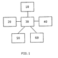
- the means of the invention presented to the figure 1 comprise sighting means 10, resetting means 20, signal processing means 30, display means 40, external means 50,60.
- the aiming means 10 comprise means 11 having the shape of a pistol.
- the body 12 of the latter is a precision support of light material, for example carbon fiber, on which are positioned on the one hand a sighting member 13, and on the other hand along three substantially perpendicular axes relative to each other.
- three optical gyroscopes 14 1 , 14 2 , 14 3 are optical fiber gyros. They allow to obtain a high precision of the measurements, their drift is weak, they support fast movements and can be used in any environment.
- gyrometers 14 1 , 14 2 , 14 3 give the speed of rotation about their axis and allow integration step by step over time, to determine the position of the means 11.
- the sighting member 13 is constituted by a viewfinder which projects a reticle at infinity, thus making it possible to aim without parallax error.
- Orifices are machined in the gun to house the electrical systems and three measuring gyrometers. The planes on which they rely, and which determine their axis of rotation are machined to ensure their perfect perpendicularity.
- These sighting means further comprise transmission control means constituted by a switch 16 in the form of a gun trigger.
- These sighting means furthermore comprise at least one sensor 17 forming part of the resetting means 20.
- This sensor may notably consist of a two-axis inclinometer, or at least two inclinometers, or at least two accelerometers, or at least two magnetic receivers. low frequency or by an electronic image sensor.
- the processing means 30 are portable and comprise a stabilized source of power supply and computing and information management means implementing software performing several functions.
- the external means comprise on the one hand means 50 for measuring the attitude (heading, roll, pitch) of the ship, in this case a navigation unit, and the latitude of the latter on the surface of the earth.
- this information is transmitted to the means of the invention by the ship's navigation means, in the form of data that can be used directly by the calculation means, by means of a transfer function to take account of the positioning of the central station. navigation relative to the resetting means.
- they comprise a weapon system 60 whose pointing is controlled from the site and azimuth values determined by the means of the invention and from values specific to the weapon system and its location on the weapon. ship.
- This attitude can be expressed in different landmarks, depending on the needs of the system that will exploit the sighting information.
- the reference frame considered is a terrestrial reference whose axes are the vertical of the place, the geographical north and the east or the west of the geographical area as explained below in the context of the function of logarithmic registration carried out by the resetting means 20.
- the algorithmic registration function which makes it possible to regularly correct the drift of the aiming instrument due to the use of gyrometers can be carried out in different ways.
- a first embodiment it is made solely from the signals emitted by three gyroscopes 14 1 , 14 2 , 14 3 arranged in trihedron on the aiming means 10 and by a two-axis inclinometer 17 disposed on the aiming means and whose the position is known in said trihedron.
- the resetting function is performed when the sighting means 10 are at rest. It should be noted that this function can also be performed when the sighting means are moved in any trajectory as described later.
- the software of the processing means 30 continuously analyzes each signal coming from each of the gyroscopes 14 1 , 14 2 , 14 3 and when the rest of the aiming means is detected, a subroutine determines in the reference formed by said trihedron, firstly, from the signals from the gyroscopes and in known manner, the direction of a straight line D1 parallel to the axis of rotation of the earth and passing by the point P where are the sighting means 10, and secondly, the direction of the vertical D2 at the point P of the place from the two signals from the inclinometer.
- the terrestrial reference is considered as invariant because during the use of the means of sight, their movements are not important enough to cause a significant change in the direction of the vertical.
- the software determines, by matrix inversion, the position of the trihedron formed by the gyroscopes in the terrestrial reference, and therefore the attitude of the aiming means and defined then the vectors of departure of the integral which makes it possible, during the movements of the sighting means, to determine the position vectors of the latter as well as its site S and its azimuth A.
- the 2-axis inclinometer is replaced for example by a three-axis accelerometer or by three accelerometers 17 2 , 17 3 , 17 4 arranged in trihedron and, as shown in FIG. figure 3 , fixed on the sighting means, their position being precisely known with respect to that of the trihedron of gyrometers.
- the software of the processing means determines, in known manner, the direction of the vertical D2 at the point P of the place.
- the software determines, from the signals coming from the gyroscopes and in known manner, the direction of a straight line D1 parallel to the axis of rotation of the earth and then the position of the terrestrial reference in the reference formed by the trihedron of gyroscopes, then the software determines, by matrix inversion, the position of the trihedron formed by the gyroscopes in the terrestrial frame, therefore the attitude of the aiming means, and finally the vectors of departure of the integral which makes it possible, during displacements aiming means, to determine the position vectors of the latter as well as its site S and its azimuth A.
- the registration function is performed regardless of the trajectory followed by the sighting means. For this reason, this type of registration is called dynamic algorithmic registration.
- the three gyrometers 14 1 , 14 2 , 14 3 make it possible to measure the rotation undergone by the aiming means 10 between two distinct instants in a Galilean coordinate system, for example that constituted by the positioning of the gyrometers 14 1 , 14 2 , 14 3 . It should be noted that in the case where the sighting means 10 are in the same position (one fixed point relative to the earth) at each of the two instants, the gyrometers have measured the earth's rotation.
- the three accelerometers 17 1 , 17 2 , 17 3 make it possible to determine at any moment the force of gravity, that is to say the expression of the "gravity" vector in the reference linked to the aiming means 10.
- the expression of this vector is, moreover, known in a reference linked to a point of the earth, this vector being vertical, oriented downwards and its norm being equal to 9.8ms -2 .
- the expressions of the gravity vector as a function of time in a terrestrial reference are therefore identical.
- the two expressions of the gravity vector of the same fixed point of the earth with two distinct instincts of the same Galilean landmark are not identical, the two vectors forming an angle which depends on the time elapsed between the two instants, and more precisely the rotation of the earth, and the latitude of the point considered.
- the purpose of the dynamic registration is to identify the initial attitude of the aiming means 10.
- R T (X t , Y t , Z t ) be the reference associated with the point P; this landmark is linked to the land.
- the X axis t is the west-east horizontal axis facing east. the horizontal axis Y t South-North facing North.
- the Z axis t is the vertical axis pointing upwards.
- R MV (X s , Y s , Z s ) be the reference linked to the aiming means 10 integrating the three gyrometers 14 1 , 14 2 , 14 3 and the three accelerometers 17 1 , 17 2 , 17 3 .
- angles K, T, and R are not known. Their identification is the goal of process implemented.
- the three accelerometers 17 1 , 17 2 , 17 3 make it possible to measure the expression of the vector "gravity" in the reference frame R MV (T i ).
- the expression of this vector in the reference frame R T (T i ) is known - equal to (0, 0, -9.8).
- K, T and R are not known. However they are calculated by an appropriate algorithm so that the calculated expressions and the expressions measured by the accelerometers of the vector "gravity", at times T 0 , T 1 ... T i ... T n , are identical.
- the algorithm used in this embodiment is of the "Downhill Simplex" type, but any other algorithm can be used as, for example, the quadratic programming of Karmakar, More and Toraldo, ...
- the software of the processing means 30 determines, as previously, the position of the trihedron formed by the gyroscopes in the terrestrial frame, and therefore the attitude of the sighting means, and then defines the starting vectors of the 'integral which allows, during the movements of the means of aiming, to determine the position vectors of these and its site S and its azimuth A.
- the calculation of the gravity vector in the reference frame R MV (T i ) requires knowledge of the latitude.
- the latter can be known or determined by a system such as a GPS, or calculated by the means of the invention.
- the software must also, and in the same way as before, in addition to the three parameters, K, T and R, calculate the latitude L at the price of a less rapid convergence.
- the periodicity of the execution of the algorithmic resetting function was a few tens of seconds.
- the resetting means comprise at least two magnetic receivers arranged non-parallel on the sighting means and rigidly, for example by means of an overmoulding and by at least one transmitter magnetic low frequency which has previously defined the position in a given frame, for example a benchmark linked to this transmitter.
- These resetting means have a range of ten meters and a position accuracy of the order of a millimeter and an angular accuracy of the order of a tenth of a degree.
- some gyrometers are sensitive to magnetic fields. In this case, it is necessary to shield them by placing a sheet of metal around them and / or to compensate for their drift due to the magnetic field by a calibration and by storing, in the means of treatment, the evolution drift as a function of the value of the magnetic field and continuously compensating drift via the software.
- the resetting means comprise at least one camera rigidly fixed to the sighting means.
- This camera generates a signal representative of the image observed.
- This signal is processed by known image processing means able to determine the position of a pattern in said image.
- This pattern can be constituted by a star, such as the moon or the sun or a star, or by a landscape or by particular patterns that have been arranged at locations whose coordinates in a predefined frame have been determined.
- the searched pattern is found, its coordinates or attitude are transmitted to the processing means and the software performs a registration of the gyroscopes performed in order to match the position signals emitted by the gyrometers with the actual position of the aiming means.
- the pattern is constituted by a star
- the camera can be mobile and when a pattern has been detected, tracking software of said pattern can handle the movement of the camera to keep the pattern in the center of the image.
- the resetting means are constituted by at least two accelerometers and preferably three rigidly disposed on the sighting means, for example by means of an overmolding, and according to a trihedron .
- accelerometers each emit a signal representative of the acceleration of the sighting means which is transmitted to the signal processing means from the gyroscopes.
- the position of this point is then determined by triangulation from the variations of accelerations generated between the two sights and site values S and azimuth A. Knowing the exact position of said point and its position calculated by triangulation, the registration of the gyroscopes is then performed by matching the calculated position with the actual position of said point.
- the drifts of the gyroscopes due to the accelerations undergone by the latter can also be compensated using these accelerometers.
- accelerometers in combination with the gyroscopes also makes it possible to perform two complementary functions.
- the first concerns the calculation of parallax and the second, passive telemetry. To achieve the latter, it is sufficient to aim for the same objective from two different positions, then, knowing the site S and the azimuth A of this lens from the signals from the gyroscopes and the distance between these two positions determined in a known manner from the signals of the accelerometers, the distance as well as the attitude of this objective are determined by triangulation.
- This goal designation has the advantage of being passive.
- the aiming means and the signal processing means from the sighting means may be portable, their mass may be less than 5 kg to allow easy use.
- the setting in motion of the sighting means 10 triggers the integration of the three incremental angles along each of the three axes related to these means.
- the attitude of the device is known at all times.
- this compliance requires two steps.
- the first consists in calculating the attitude of the aiming means in the terrestrial or geographical reference frame with respect to a magnetic transmitter or in relation to a pattern whose position does not vary or very little.
- the second consists in expressing the attitude in the exploitation marker, in this case the reference of the weapon system.
- This marker may be located several tens of meters from the sighting means, and therefore the parallax error may not be negligible, especially if the objects referred to are close, these objects may be swimmers or light craft.
- the field of view is divided into two areas.
- a standard distance of about 4,000 meters is used to correct the parallax.
- a data filtering software is integrated so as to stabilize the output signal.
- This filtering can be of the low-pass type or a KALMANN type filter so as to take into account the evolutions of the targets in a given template without having a drag.
- the movement can be fast enough, and incremental angles measured by the measurement system large enough, adequate modeling can be reduced to the previous conditions.
- the aiming means may include an image acquisition device that is used in this case to allow image stabilization to filter parasitic movements, to allow by image processing to identify the objective or by image processing to calculate the exact position of the target with respect to the aim of the operator.
- the attitude of the aiming instrument is determined by continuous treatment. Before any target designation, and in order to implement the algorithmic registration function, the aiming instrument is at rest with a known position.
- the software implemented by the processing means 30 is intended to process the raw data provided by the aiming instrument, a device that enables the operator of the means according to the invention, by targeting a target, to determine his site. and its azimuth.
- the target designation function is always active when the aiming instrument is in operational mode, ie out of its rest position. It is necessary that the processing time of the gyroscopic data is minimal, for example of the order of a few milliseconds, in order to be able to process the maximum of data coming out of the gyrometers, and thus to follow as well as possible the evolution of the increments of angle and angles that are deduced, in order to limit the error during the treatment. Depending on the size of the increments of angles coming from the gyrometers, a modeling is put in place to overcome as much as possible the limits of commutativity of the rotations in the space.
- the transmission function is very simple, since it consists of sending the calculated site values and the azimuth in the absolute reference of the building at time t, to a memory and to the weapon system and / or the means. visualization for display.
- This function is triggered by the passage of the switch 16 from the open position to the closed position. It is accompanied by the emission of an audible signal and / or a light signal and the display of positive information on the means of viewing.
- the processing of the input data is performed as follows:
- the values of the cap K, the roll Rr and the pitch Ta of the building are acquired.
- the aiming means 10 are at rest and the software of the processing means 30 implements the algorithmic rescaling routine of the gyrometers.
- the position of the rest support relative to the building is entered as a parameter. This makes it possible to determine the position of the instrument of referred to 10, when it is at rest, in the terrestrial or geographical reference with respect to a magnetic transmitter or in relation to a pattern whose position does not vary or very little relative to the building.
- switch 16 When the trigger is depressed, switch 16 is closed, and the trigger variable goes from 0 to 1 on the screen.
- the registration variable goes from 0 to 1 on the screen.
- the implementation of the means of the invention is carried out by an operator.
- the sighting means 10 are at rest, for example placed or hung on any plane.
- the operator sees a target, he takes the aiming means 10 and then points them, with the aid of the aiming member 13, towards the target and presses the switch 16 when he considers that they are correctly positioned relative to the target. Therefore the means 30 calculate the site and the azimuth of the target and transmit these values to the weapon system which controls the orientation of the weapon according to these values and the attitude variations of the ship from said transmission of the values, these variations being, as previously mentioned, determined by the means 50.
- the shooter can aim at another target and press the switch 16.
- the processing means 30 then calculate the site and the azimuth of the new target and transmit these values to the weapon system which stores in memory said values and can direct the weapon towards this new target immediately after firing towards the first target.
- the shooter can successively target several targets in a minimum of time, without having to wait for the end of the firing sequence of the weapon which optimizes the total time required for the corresponding shots and thus reduces the vulnerability of the boat.
- the shooter can, after acquisition of the target or different targets, perform additional tasks or move without the weapon system reacts to its movements.
- the acquisition of the gyrometers is done with a pitch Dt of between 5 ms and 50 ms. These values are integrated and it is known to model numerically this integration in order to obtain accurate results, for example with Adams-Moulton-Bashforth, Runge-Kutta or Burlirsch-Stoer prediction-correction methods. However, with portable computing means, it is not possible to perform more complex calculations in real time.
- One of the aims of the invention is to remedy this problem by proposing an integration method of successively performing, from the gyroscopic values obtained between the time to and the time t1, first calculations with complex modeling not which can operate in real time but gives accurate results, and then from the gyro values obtained between time t1 and time t2, second calculations with simplified modeling and capable of being implemented in real time.
- This succession of steps has the advantage of being able to lead to site and azimuth calculations in real time with respect to the closing of the switch 16 and, given this objective, gives more accurate results than use alone. complex modeling or simplified modeling.
- the sighting means can be applied to a helmet, such as that described in the patent US 4,722,601 , to a banner or binoculars and the software may include a self-adaptive algorithm for calculating the drift of the gyrometers.
- a GPS system or equivalent may be associated with the processing means in order to corroborate the position information determined from the signals from the gyroscopes.
- a laser range finder can be used to determine the distance of an objective or corroborate position calculations made from signals from accelerometers and gyroscopes.
- the various measurements made can advantageously be used to check the state of rest of the aiming device as well as to perform correlations, calibrations and error checks.
Landscapes
- Engineering & Computer Science (AREA)
- Radar, Positioning & Navigation (AREA)
- Remote Sensing (AREA)
- General Engineering & Computer Science (AREA)
- Automation & Control Theory (AREA)
- General Physics & Mathematics (AREA)
- Physics & Mathematics (AREA)
- Navigation (AREA)
- Gyroscopes (AREA)
- Aiming, Guidance, Guns With A Light Source, Armor, Camouflage, And Targets (AREA)
- Control Of Stepping Motors (AREA)
- Radar Systems Or Details Thereof (AREA)
- Variable-Direction Aerials And Aerial Arrays (AREA)
- Control Of Position Or Direction (AREA)
Claims (34)
- Vorrichtung, die zur Bestimmung der Richtung eines Ziels in einer vordefinierten Markierung geeignet ist und vom dem Typ, umfassend Mittel zum Anvisieren (10), umfassend ein Organ zum Anvisieren (13), drei Gyrometer (141, 142, 143), die gemäß drei nicht koplanaren Achsen angeordnet sind, Steuermittel (18), Einstellmittel (20) dieser Mittel zum Anvisieren (10) und Verarbeitungsmittel (30) von Signalen, die aus Mitteln zum Anvisieren (10) stammen, wobei diese Verarbeitungsmittel (30) geeignet sind, die Richtung zwischen den Mitteln zum Anvisieren (10) und dem Ziel zu bestimmen und sie auf Anzeigemittel (40) oder auf äußere Mittel (50, 60) zu übertragen, sowie Steuermittel (16) der Übertragung auf Anzeigemittel (40) oder auf äußere Mittel (50, 60), Werte, die die Richtung zwischen den Mitteln zum Anvisieren (10) und dem Ziel darstellen, wobei die Vorrichtung dadurch gekennzeichnet ist, dass die Einstellmittel wenigstens einen nicht gyroskopischen Sensor (17) umfassen, der auf den Mitteln zum Anvisieren (10) angeordnet ist und geeignet ist, ein Signal zu seiner Übertragung auf die genannten Verarbeitungsmittel (30) zu senden, wobei die Verarbeitungsmittel geeignet sind, die Haltung der Mittel zum Anvisieren in einer terrestrischen Markierung ausgehend von Signalen zu bestimmen, die aus den genannten Gyrometern (141, 142, 143) und dem genannten nicht gyroskopischen Sensor stammen.
- Vorrichtung gemäß Anspruch 1, dadurch gekennzeichnet, dass die Verarbeitungsmittel (30) geeignet sind, einerseits die Richtung einer Geraden D1, die parallel zur Rotationsachse der Erde und durch den Punkt P verläuft, in dem sich die Mittel zum Anvisieren (10) ausgehend von Signalen befinden, die aus den Gyroskopen stammen, und andererseits die Richtung der Vertikalen D2 an dem Punkt P des Ortes, ausgehend von den Signalen zu bestimmen, die aus den genannten Gyrometern (141, 142, 143) und dem genannten nicht gyroskopischen Sensor (17) stammen.
- Vorrichtung gemäß Anspruch 1 oder 2, in dem die Achsen der terrestrischen Markierung die Vertikale des Ortes, der geographische Norden und der Osten oder der geographische Westen sind.
- Vorrichtung gemäß Anspruch 1 bis 3, dadurch gekennzeichnet, dass wenigstens ein Sensor aus einem Neigungsmesser mit zwei Achsen oder aus wenigstens zwei Neigungsmessern gebildet wird.
- Vorrichtung gemäß Anspruch 1 bis 3, dadurch gekennzeichnet, dass der genannte wenigstens eine Sensor aus einem Beschleunigungsmesser mit mehreren Achsen oder aus wenigstens zwei Beschleunigungsmessern gebildet wird.
- Vorrichtung gemäß Anspruch 1 bis 3, dadurch gekennzeichnet, dass der genannte wenigstens eine Sensor aus einem elektronischen Bildsensor gebildet wird.
- Vorrichtung gemäß Anspruch 6, dadurch gekennzeichnet, dass der elektronische Bildsensor geeignet ist, ein Bilder darstellendes Signal zu generieren und das auf Verarbeitungsmittel dieses Signals übertragen wird, die geeignet sind, die Position eines Motivs in dem genannten Bild zu bestimmen.
- Vorrichtung gemäß Anspruch 7, dadurch gekennzeichnet, dass Bildverarbeitungsmittel, die dem elektronischen Bildsensor zugeordnet sind, den Ausgleich der "Bewegung" des Operators erlauben.
- Vorrichtung gemäß Anspruch 7 oder 8, dadurch gekennzeichnet, dass die Verarbeitungsmittel der Mittel zum Anvisieren geeignet sind, die Bewegung des Operators ausgehend von dem Wert des optischen Feldes des elektronischen Bildsensors auszugleichen.
- Vorrichtung gemäß Anspruch 8 und 9, dadurch gekennzeichnet, dass die Verarbeitungsmittel der Mittel zum Anvisieren geeignet sind, das winkelförmige Feld des elektronischen Bildsensors ausgehend von der Relation zwischen der Bewegung des Operators, die aus dem Signal des elektronischen Sensors stammt, und des der Mittel zum Anvisieren zu bestimmen.
- Vorrichtung gemäß Anspruch 6 bis 10, dadurch gekennzeichnet, dass die Verarbeitungsmittel der Mittel zum Anvisieren geeignet sind, ausgehend von Signalen des elektronischen Bildsensors und der Mittel zum Anvisieren ein unterzeichnetes Bild zu generieren.
- Vorrichtung gemäß Anspruch 11, dadurch gekennzeichnet, dass die Verarbeitungsmittel der Mittel zum Anvisieren geeignet sind, ausgehend von unterzeichneten Bildern die globale Landschaft mit Positionsinformationen für unterschiedliche Bereiche derselben nachzubilden.
- Vorrichtung gemäß Anspruch 11 und 12, dadurch gekennzeichnet, dass sie Anzeigemittel der genannten unterzeichneten Bilder und / oder der nachgebildeten Landschaft umfasst.
- Vorrichtung gemäß Anspruch 1 bis 13, dadurch gekennzeichnet, dass die Verarbeitungsmittel der Mittel zum Anvisieren geeignet sind, zur Übertragung von Identifikationselementen des Ziels und / oder der Feststellung der absoluten Richtung der Mittel zum Anvisieren beizutragen.
- Vorrichtung gemäß Anspruch 1 bis 14, dadurch gekennzeichnet, dass sie Registrierungsmittel des Signals umfasst, das aus dem elektronischen Sensor stammt, und / oder dass sie Anzeigemittel der genannten Bilder sowie bestimmter Informationen umfasst, wie z. B.. die Richtung des anvisierten Ziels, seine Entfernung und / oder seine Art.
- Vorrichtung gemäß Anspruch 1 bis 3, dadurch gekennzeichnet, dass der genannte, wenigstens eine Sensor aus wenigstens zwei magnetischen Empfängern gebildet wird.
- Vorrichtung gemäß Anspruch 16, dadurch gekennzeichnet, dass sie einen magnetischen Sender umfasst.
- Vorrichtung gemäß Anspruch 1 bis 17, dadurch gekennzeichnet, dass sie drei optische Gyrometer, z. B. Glasfasergyrometer, umfasst.
- Vorrichtung gemäß Anspruch 1 bis 18, dadurch gekennzeichnet, dass die Verarbeitungsmittel eine Stromversorgungsquelle und Berechnungs- und Verwaltungsmittel von Informationen umfassen, die eine Software umsetzen, welche mehrere Funktionen realisiert.
- Vorrichtung gemäß Anspruch 19, dadurch gekennzeichnet, dass die Software drei Hauptfunktionen realisiert:* Die Funktion zur Bezeichnung von Zielen, die die Erfassung der Daten des Instruments zum Anvisieren übernimmt und sie verarbeitet, um den Standort und den gewünschten Azimut zu erhalten,* Die Übertragungsfunktion, die die Azimut- Standortdaten zur Anzeige auf den Anzeigemittel und / oder einem Waffensystem versendet,* Die Funktion zum Feststellen der absoluten Position, die die regelmäßige Korrektur der auf die Verwendung des Gyrometers zurückzuführende Abweichung des Instruments zum Anvisieren erlaubt.
- Vorrichtung gemäß Anspruch 20, dadurch gekennzeichnet, dass die Software darüber hinaus eine Funktion zum Anvisieren des Betriebszustandes der Elemente der Erfindung realisiert.
- Vorrichtung gemäß Anspruch 1 bis 21, dadurch gekennzeichnet, dass die Mittel zum Anvisieren die Erfassung der geographischen Position durch funkelektrische Positionierungsmittel, z. B. Satellitenmittel vom Typ GPS, umfassen.
- Vorrichtung gemäß Anspruch 1 bis 22, dadurch gekennzeichnet, dass die Mittel zum Anvisieren einen aktiven Telemeter umfassen.
- Vorrichtung gemäß Anspruch 1 bis 23, dadurch gekennzeichnet, dass die Mittel zum Anvisieren wenigstens zwei Beschleunigungsmesser umfassen und dass die Verarbeitungsmittel Triangulierungsmittel umfassen, die geeignet sind, eine diskrete Triangulierung durchzuführen.
- Einstellverfahren einer Vorrichtung, die geeignet ist, die Richtung eines Ziels in einer ersten vordefinierten Markierung zu bestimmen und von dem Typ, umfassend Mittel zum Anvisieren (10), umfassend ein erstes Organ zum Anvisieren (13), drei Gyrometer (141, 142, 143), die gemäß drei nicht koplanaren Achsen angeordnet sind, und Verarbeitungsmittel (30) von Signalen, die aus Mitteln zum Anvisieren (10) stammen, wobei diese Verarbeitungsmittel (30) geeignet sind, die Richtung zwischen den Mitteln zum Anvisieren (10) und dem Ziel zu bestimmen, wobei das Verfahren dadurch gekennzeichnet, ist, dass es eine Stufe umfasst, in der die Verarbeitungsmittel ausgehend von dem Signal, das durch einen gyroskopischen Sensor (17) gesendet wird, welcher auf den Mitteln zum Anvisieren (10) angeordnet ist und von denen, die von den Gyrometern gesendet werden, die Haltung der Mittel zum Anvisieren in einer zweiten vordefinierten Markierung bestimmen, wobei die zweite Markierung eine terrestrische Markierung ist.
- Verfahren gemäß Anspruch 25, dadurch gekennzeichnet, dass es eine Stufe zur Bestimmung einerseits der Richtung einer Geraden D1, die parallel zur Rotationsachse der Erde und durch den Punkt P verläuft, in dem sich die Mittel zum Anvisieren 10 befinden, ausgehend von den Signalen, die aus den Gyroskopen stammen, und andererseits der Richtung der Vertikalen D2 am Punkt P des Ortes ausgehend von Signalen, die von dem genannten nicht gyroskopischen Sensor (17) stammen, umfasst.
- Verfahren gemäß Anspruch 26, dadurch gekennzeichnet, dass es eine komplementäre Stufe zur Bestimmung der Richtung des geographischen Nordens umfasst, wobei diese Richtung durch die Schnittlinie der Ebene, die durch die Geraden D1 und D2 erhalten wird, mit der lotrechten Ebene zu D2, die durch P verläufe, erhalten wird.
- Verfahren gemäß Anspruch 25, für dessen Ümsetzung einerseits die Mittel zum Anvisieren wenigstens drei Sensoren umfassen, und zwar drei magnetische Empfänger, und andererseits die Vorrichtung einen magnetischen Sender umfasst, wobei das Verfahren dadurch gekennzeichnet ist, dass die Vierarbeitungsmittel (30) die Position und die Ausrichtung berechnen, und zwar die Haltung der Mittel zum Anvisieren (10) ausgehend von Signalen, die aus magnetischen Sensoren und der erwarteten Kartographie des magnetischen Feldes stammen, das zuvor in den Speicher dieser Verarbeitungsmittel eingegeben wurde.
- Verfahren gemäß Anspruch 25, für dessen Umsetzung die Mittel zum Anvisieren einen elektronischen Bildsensor umfassen, wie z. B. eine steif auf den Mitteln zum Anvisieren angebrachte Kamera, wobei diese Kamera ein Signal generiert, das das beobachtete Bild darstellt, wobei das Verfahren dadurch gekennzeichnet wird, dass es eine Stufe umfasst, in der die Bildverarbeitungsmittel geeignet sind, die Position eines Motivs in dem genannten Bild zu bestimmen, wobei die Position dieses Motivs bekannt ist.
- Einstellverfahren gemäß Anspruch 26 oder 27, dadurch gekennzeichnet, dass es eine Stufe umfasst, bei der die Verarbeitungsmittel (30) den Wert des Gravitätsvektors entweder kontinuierlich oder zu mehreren Momenten T0, T1, Ti, ..., Tn ausgehend von dem Signal bestimmen, das aus dem genannten nicht gyroskopischen, auf den Mitteln zum Anvisieren (10) angeordneten Sensor (17) stammt.
- Verfahren gemäß Anspruch 25 bis 30, dadurch gekennzeichnet, dass es eine Stufe umfasst, in der die Verarbeitungsmittel Winkel K, T und R bestimmen, wie z. B.: Da:- P der Punkt der Oberfläche der Erde ist, in dem sich die Mittel zum Anvisieren befinden,- RT (Xt, Yt, Zt) eine Markierung ist, die dem Punkt P zugeordnet ist und mit der Erde der verbunden ist, wobei die Achse Xt die horizontale, nach Osten ausgerichtete Achse Westen-Osten ist, die Achse Yt die horizontale, nach Norden ausgerichtete Achse Süden-Norden ist und die Achse Zt die nach oben ausgerichtete vertikale Achse ist.- RMV (Xs, Ys, Zs) eine Markierung ist, die mit den Mitteln zum Anvisieren (10) verbunden ist, die die drei Gyrometer (141, 142, 143) und den genannten wenigstens einen nicht gyroskopischen Sensor beinhalten.
die sukzessiven Rotationen eines Winkels -K um Zt, dann einen Winkel -T um die Achse, die aus der vorherigen Rotation resultieren, die auf die Achse Xt angewendet wird, dann einen Winkel -R um die Achse, der aus den 2 vorherigen Rotationen resultiert, die auf die Achse Yt angewendet wird,
führt die Markierung Rt auf die Markierung RMv. - Verfahren gemäß Anspruch 31, dadurch gekennzeichnet, dass es eine erste Stufe umfasst, die in der Berechnung des Ausdrucks der Markierung Rt (Ti) in der Markierung RMV (T1) besteht, in dem sie den folgenden Rotationen unterzogen wird:- der Rotation eines Winkels -α in Abhängigkeit von der zwischen den Augenblicken T0 und T1 abgelaufenen Zeit
 - den zuvor beschriebenen Winkelrotationen -K, -T und -R,- der Rotation, die aus der Integration der Winkelinkremente resultiert, die durch die Gyrometer gemessen wird,
dann, in einer zweiten Stufe, der Bestimmung der Winkel K, T und R, entweder per Inversion der Egalisierung der berechneten Ausdrücke und der gemessenen Ausdrücke des Gravitätsvektors oder per Minimierung einer Fehlerfunktion mit einem Forschungsalgorxthmus des Minimums einer Funktion mit mehreren Parametern auf einer Datenpopulation, wie z. B. einem Algorithmus vom Typ Simplex-Algorithmus, simuliertes Tempern oder durch jeden anderen Algorithmus, wie z. B. die quadratische Programmierung nach Kamakar, More und Toraldo, usw. - Verfahren gemäß Anspruch 30 bis 32, dadurch gekennzeichnet, dass es eine Stufe zur Bestimmung des Breitengrades des Ortes umfasst, an dem sich die Mittel zum Anvisieren befinden.
- Verfahren gemäß Anspruch 32, dadurch gekennzeichnet, dass die genannte zweite Stufe darüber hinaus in der Berechnung des Breitengrades L, zuzüglich zu den Winkeln K, T und R besteht.
Applications Claiming Priority (3)
| Application Number | Priority Date | Filing Date | Title |
|---|---|---|---|
| FR0105768 | 2001-04-27 | ||
| FR0105768A FR2824132B1 (fr) | 2001-04-27 | 2001-04-27 | Dispositif, et procede associe, apte a determiner la direction d'une cible |
| PCT/FR2002/001478 WO2002088616A2 (fr) | 2001-04-27 | 2002-04-29 | Dispositif, et procede associe, apte a determiner la direction d'une cible |
Publications (2)
| Publication Number | Publication Date |
|---|---|
| EP1407214A2 EP1407214A2 (de) | 2004-04-14 |
| EP1407214B1 true EP1407214B1 (de) | 2009-07-01 |
Family
ID=8862822
Family Applications (1)
| Application Number | Title | Priority Date | Filing Date |
|---|---|---|---|
| EP02738206A Expired - Lifetime EP1407214B1 (de) | 2001-04-27 | 2002-04-29 | Vorrichtung und dazugehöriges verfahren zum bestimmen der richtung eines zieles |
Country Status (7)
| Country | Link |
|---|---|
| US (1) | US20040134341A1 (de) |
| EP (1) | EP1407214B1 (de) |
| AT (1) | ATE435413T1 (de) |
| AU (1) | AU2002313023A1 (de) |
| DE (1) | DE60232795D1 (de) |
| FR (1) | FR2824132B1 (de) |
| WO (1) | WO2002088616A2 (de) |
Families Citing this family (30)
| Publication number | Priority date | Publication date | Assignee | Title |
|---|---|---|---|---|
| US7749089B1 (en) | 1999-02-26 | 2010-07-06 | Creative Kingdoms, Llc | Multi-media interactive play system |
| US6761637B2 (en) | 2000-02-22 | 2004-07-13 | Creative Kingdoms, Llc | Method of game play using RFID tracking device |
| US7445550B2 (en) | 2000-02-22 | 2008-11-04 | Creative Kingdoms, Llc | Magical wand and interactive play experience |
| US7878905B2 (en) | 2000-02-22 | 2011-02-01 | Creative Kingdoms, Llc | Multi-layered interactive play experience |
| US7066781B2 (en) | 2000-10-20 | 2006-06-27 | Denise Chapman Weston | Children's toy with wireless tag/transponder |
| US20070066396A1 (en) | 2002-04-05 | 2007-03-22 | Denise Chapman Weston | Retail methods for providing an interactive product to a consumer |
| US6967566B2 (en) | 2002-04-05 | 2005-11-22 | Creative Kingdoms, Llc | Live-action interactive adventure game |
| US7674184B2 (en) | 2002-08-01 | 2010-03-09 | Creative Kingdoms, Llc | Interactive water attraction and quest game |
| FR2852405B3 (fr) * | 2003-03-14 | 2005-06-03 | Dispositif et procede associe apte a determiner la direction d'une cible | |
| US9446319B2 (en) | 2003-03-25 | 2016-09-20 | Mq Gaming, Llc | Interactive gaming toy |
| US8074394B2 (en) * | 2005-03-08 | 2011-12-13 | Lowrey Iii John William | Riflescope with image stabilization |
| JP4805633B2 (ja) | 2005-08-22 | 2011-11-02 | 任天堂株式会社 | ゲーム用操作装置 |
| US8313379B2 (en) | 2005-08-22 | 2012-11-20 | Nintendo Co., Ltd. | Video game system with wireless modular handheld controller |
| US7927216B2 (en) | 2005-09-15 | 2011-04-19 | Nintendo Co., Ltd. | Video game system with wireless modular handheld controller |
| US7942745B2 (en) | 2005-08-22 | 2011-05-17 | Nintendo Co., Ltd. | Game operating device |
| US8870655B2 (en) | 2005-08-24 | 2014-10-28 | Nintendo Co., Ltd. | Wireless game controllers |
| JP4262726B2 (ja) | 2005-08-24 | 2009-05-13 | 任天堂株式会社 | ゲームコントローラおよびゲームシステム |
| US8308563B2 (en) | 2005-08-30 | 2012-11-13 | Nintendo Co., Ltd. | Game system and storage medium having game program stored thereon |
| US8157651B2 (en) | 2005-09-12 | 2012-04-17 | Nintendo Co., Ltd. | Information processing program |
| JP4530419B2 (ja) * | 2006-03-09 | 2010-08-25 | 任天堂株式会社 | 座標算出装置および座標算出プログラム |
| JP4151982B2 (ja) | 2006-03-10 | 2008-09-17 | 任天堂株式会社 | 動き判別装置および動き判別プログラム |
| JP4684147B2 (ja) | 2006-03-28 | 2011-05-18 | 任天堂株式会社 | 傾き算出装置、傾き算出プログラム、ゲーム装置およびゲームプログラム |
| FR2929700B1 (fr) * | 2006-10-23 | 2016-02-05 | Sofresud | Dispositif decentralise d'autodefense comprenant un pointeur portable et mobile apte a assurer en urgence la defense rapprochee d'un navire ou d'une plate-forme en mer contre une menace de surface. |
| JP5127242B2 (ja) | 2007-01-19 | 2013-01-23 | 任天堂株式会社 | 加速度データ処理プログラムおよびゲームプログラム |
| US8305192B2 (en) * | 2008-11-21 | 2012-11-06 | Symbol Technologies, Inc. | RFID reader with automatic near/far field interrogation mode switching, and related operating methods |
| US20120059575A1 (en) * | 2010-02-05 | 2012-03-08 | Honeywell International Inc. | Target locator device and methods |
| FR3057656B1 (fr) * | 2016-10-14 | 2019-04-05 | Sofresud | Dispositif visuel pour la designation d’objectifs et procede de designation d’objectif utilisant ledit dispositif |
| FR3063006B1 (fr) * | 2017-02-20 | 2024-11-22 | Vincent Pomero | Systeme d'orientation chirurgical utilisant la geometrie des os pour un positionnement repetable |
| FR3089283B1 (fr) | 2018-11-29 | 2021-03-12 | Ixblue | Module autonome optronique de pointage de cible géolocalisé pour système portable et système correspondant |
| FR3147360A1 (fr) | 2023-03-30 | 2024-10-04 | Seaowl Technology Solutions | Système de téléopération |
Family Cites Families (14)
| Publication number | Priority date | Publication date | Assignee | Title |
|---|---|---|---|---|
| US4012989A (en) | 1975-04-21 | 1977-03-22 | Summa Corporation | Inertial free-sight system |
| FR2536936B1 (fr) * | 1982-11-30 | 1988-10-07 | Thomson Csf | Circuit generateur d'horizon, notamment pour simulateur d'entrainement au tir au canon |
| GB2143948B (en) * | 1983-07-23 | 1986-08-06 | Ferranti Plc | Apparatus for determining the direction of a line of sight |
| ATE45420T1 (de) * | 1986-01-24 | 1989-08-15 | Litef Gmbh | Einrichtung zur stabilisierung hochdynamischer geraete auf einem niederdynamischen traeger. |
| FR2668447B1 (fr) * | 1990-10-29 | 1993-01-22 | Aerospatiale | Systeme pour l'alignement de la centrale inertielle d'un vehicule porte sur celle d'un vehicule porteur. |
| JP2874348B2 (ja) | 1991-01-10 | 1999-03-24 | 住友電気工業株式会社 | ジャイロのバイアス補正装置 |
| FR2673711B1 (fr) * | 1991-03-07 | 1995-09-15 | Aerospatiale | Procede et systeme d'harmonisation autonome d'equipements a bord d'un vehicule, utilisant des moyens de mesure du champ de gravite terrestre. |
| FR2673712B1 (fr) * | 1991-03-07 | 1993-06-18 | Aerospatiale | Procede et systeme d'harmonisation autonome d'equipements a bord d'un vehicule, utilisant des moyens de mesure des champs de gravite et magnetique terrestres. |
| DE4205869A1 (de) * | 1992-02-26 | 1993-09-02 | Teldix Gmbh | Einrichtung zur bestimmung der relativen orientierung eines koerpers |
| US5822713A (en) * | 1993-04-05 | 1998-10-13 | Contraves Usa | Guided fire control system |
| US5568152A (en) * | 1994-02-04 | 1996-10-22 | Trimble Navigation Limited | Integrated image transfer for remote target location |
| FR2728339B1 (fr) | 1994-12-14 | 1997-04-04 | Aerospatiale | Procede et dispositif pour estimer des biais gyrometriques |
| US5854843A (en) * | 1995-06-07 | 1998-12-29 | The United States Of America As Represented By The Secretary Of The Air Force | Virtual navigator, and inertial angular measurement system |
| FR2758625B1 (fr) * | 1997-01-17 | 1999-03-19 | Sofresud | Dispositif apte a determiner la direction d'une cible dans un repere predefini |
-
2001
- 2001-04-27 FR FR0105768A patent/FR2824132B1/fr not_active Expired - Fee Related
-
2002
- 2002-04-29 US US10/475,659 patent/US20040134341A1/en not_active Abandoned
- 2002-04-29 AT AT02738206T patent/ATE435413T1/de not_active IP Right Cessation
- 2002-04-29 DE DE60232795T patent/DE60232795D1/de not_active Expired - Lifetime
- 2002-04-29 AU AU2002313023A patent/AU2002313023A1/en not_active Abandoned
- 2002-04-29 EP EP02738206A patent/EP1407214B1/de not_active Expired - Lifetime
- 2002-04-29 WO PCT/FR2002/001478 patent/WO2002088616A2/fr not_active Ceased
Also Published As
| Publication number | Publication date |
|---|---|
| US20040134341A1 (en) | 2004-07-15 |
| FR2824132B1 (fr) | 2007-07-13 |
| WO2002088616A3 (fr) | 2003-11-06 |
| AU2002313023A1 (en) | 2002-11-11 |
| ATE435413T1 (de) | 2009-07-15 |
| WO2002088616A9 (fr) | 2003-12-24 |
| FR2824132A1 (fr) | 2002-10-31 |
| EP1407214A2 (de) | 2004-04-14 |
| DE60232795D1 (de) | 2009-08-13 |
| WO2002088616A2 (fr) | 2002-11-07 |
Similar Documents
| Publication | Publication Date | Title |
|---|---|---|
| EP1407214A2 (de) | Vorrichtung und dazugehöriges verfahren zum bestimmen der richtung eines zieles | |
| US8955749B2 (en) | Aiming system | |
| EP2932182B1 (de) | Verfahren zur genauen geolokalisierung eines bildsensors an bord eines flugzeugs | |
| FR3100895A1 (fr) | Procédé et système de positionnement automatique de drones en essaim | |
| EP0953140B1 (de) | Vorrichtung zum bestimmen der richtung eines zieles in einer vorbestimmten indexmarkierung | |
| EP0148704A2 (de) | Überwachungssystem mittels eines gelenkten Flugkörpers zur Lokalisierung eines Zieles | |
| EP3273318A1 (de) | Autonomes aufnahmesystem von animierten bildern durch eine drohne mit zielverfolgung und verbesserter lokalisierung des ziels | |
| EP2495531B1 (de) | Verfahren zum Messen der Stabilität einer Sichtlinie und entsprechender Sternsensor | |
| FR2542863A1 (fr) | Systeme heliporte de localisation et de determination des parametres de deplacement d'une cible, et procede pour sa mise en oeuvre | |
| EP3123209B1 (de) | Absolutvektor-gravimeter und verfahren zur messung eines absoluten schwerkraftvektors | |
| EP0484202A1 (de) | Anordnung für die Ausrichtung des Inertialsystems eines getragenen Fahrzeugs auf das eines Trägerfahrzeuges | |
| EP3384241A1 (de) | Trägheitsnavigationssystem mit verbesserter genauigkeit | |
| US20240230341A1 (en) | Celestial navigation with computer controlled dead reconning | |
| EP4004492B1 (de) | Verfahren und vorrichtung zum kalibrieren einer trägheitseinheit | |
| FR2859782A1 (fr) | Systemes d'armes | |
| FR2852405A1 (fr) | Dispositif et procede associe apte a determiner la direction d'une cible | |
| FR3112873A1 (fr) | Procédé et dispositif de prédiction de l’état d’une cible mobile | |
| CA2249474C (fr) | Dispositif apte a determiner la direction d'une cible dans un repere predefini | |
| EP0016684A1 (de) | Vorrichtung zur Bestimmung einer Visierlinie | |
| EP3728994B1 (de) | Verfahren zur lokalisierung einer montageebene, die einen teil eines fahrzeugs bildet, und zugehörige vorrichtungen und verfahren | |
| EP4030409B1 (de) | Simulator und simulationsverfahren mit erhöhter genauigkeit, insbesondere waffensystemsimulator, und waffensystem, das mit einem solchen simulator versehen ist | |
| EP4471509B1 (de) | Verfahren zur validierung einer detektion des durchtritts der karmanlinie durch ein tragbares gerät, insbesondere eine uhr | |
| EP4430362B1 (de) | Hybrides trägheits-/sternnavigationsverfahren mit harmonisierungsleistungsindikator | |
| EP1840692B1 (de) | Verfahren zur Steuerung und/oder Lenkung eines Projektils und Vorrichtung zum Steuern und/oder Lenken mit Hilfe dieses Verfahrens | |
| FR3157574A1 (fr) | Procédé de commande d'un dispositif optronique embarqué et dispositif optronique embarqué correspondant |
Legal Events
| Date | Code | Title | Description |
|---|---|---|---|
| PUAI | Public reference made under article 153(3) epc to a published international application that has entered the european phase |
Free format text: ORIGINAL CODE: 0009012 |
|
| AK | Designated contracting states |
Kind code of ref document: A2 Designated state(s): AT BE CH CY DE DK ES FI FR GB GR IE IT LI LU MC NL PT SE TR |
|
| AX | Request for extension of the european patent |
Extension state: AL LT LV MK RO SI |
|
| 17P | Request for examination filed |
Effective date: 20041004 |
|
| D17P | Request for examination filed (deleted) | ||
| R17P | Request for examination filed (corrected) |
Effective date: 20041004 |
|
| 17Q | First examination report despatched |
Effective date: 20070629 |
|
| GRAP | Despatch of communication of intention to grant a patent |
Free format text: ORIGINAL CODE: EPIDOSNIGR1 |
|
| GRAS | Grant fee paid |
Free format text: ORIGINAL CODE: EPIDOSNIGR3 |
|
| GRAA | (expected) grant |
Free format text: ORIGINAL CODE: 0009210 |
|
| AK | Designated contracting states |
Kind code of ref document: B1 Designated state(s): AT BE CH CY DE DK ES FI FR GB GR IE IT LI LU MC NL PT SE TR |
|
| REG | Reference to a national code |
Ref country code: GB Ref legal event code: FG4D Free format text: NOT ENGLISH |
|
| REG | Reference to a national code |
Ref country code: CH Ref legal event code: EP |
|
| REG | Reference to a national code |
Ref country code: IE Ref legal event code: FG4D |
|
| REF | Corresponds to: |
Ref document number: 60232795 Country of ref document: DE Date of ref document: 20090813 Kind code of ref document: P |
|
| REG | Reference to a national code |
Ref country code: CH Ref legal event code: NV Representative=s name: ABREMA AGENCE BREVET ET MARQUES, GANGUILLET |
|
| NLV1 | Nl: lapsed or annulled due to failure to fulfill the requirements of art. 29p and 29m of the patents act | ||
| PG25 | Lapsed in a contracting state [announced via postgrant information from national office to epo] |
Ref country code: ES Free format text: LAPSE BECAUSE OF FAILURE TO SUBMIT A TRANSLATION OF THE DESCRIPTION OR TO PAY THE FEE WITHIN THE PRESCRIBED TIME-LIMIT Effective date: 20091012 Ref country code: SE Free format text: LAPSE BECAUSE OF FAILURE TO SUBMIT A TRANSLATION OF THE DESCRIPTION OR TO PAY THE FEE WITHIN THE PRESCRIBED TIME-LIMIT Effective date: 20090701 Ref country code: FI Free format text: LAPSE BECAUSE OF FAILURE TO SUBMIT A TRANSLATION OF THE DESCRIPTION OR TO PAY THE FEE WITHIN THE PRESCRIBED TIME-LIMIT Effective date: 20090701 Ref country code: AT Free format text: LAPSE BECAUSE OF FAILURE TO SUBMIT A TRANSLATION OF THE DESCRIPTION OR TO PAY THE FEE WITHIN THE PRESCRIBED TIME-LIMIT Effective date: 20090701 |
|
| REG | Reference to a national code |
Ref country code: IE Ref legal event code: FD4D |
|
| PG25 | Lapsed in a contracting state [announced via postgrant information from national office to epo] |
Ref country code: NL Free format text: LAPSE BECAUSE OF FAILURE TO SUBMIT A TRANSLATION OF THE DESCRIPTION OR TO PAY THE FEE WITHIN THE PRESCRIBED TIME-LIMIT Effective date: 20090701 |
|
| PG25 | Lapsed in a contracting state [announced via postgrant information from national office to epo] |
Ref country code: PT Free format text: LAPSE BECAUSE OF FAILURE TO SUBMIT A TRANSLATION OF THE DESCRIPTION OR TO PAY THE FEE WITHIN THE PRESCRIBED TIME-LIMIT Effective date: 20091102 |
|
| PG25 | Lapsed in a contracting state [announced via postgrant information from national office to epo] |
Ref country code: DK Free format text: LAPSE BECAUSE OF FAILURE TO SUBMIT A TRANSLATION OF THE DESCRIPTION OR TO PAY THE FEE WITHIN THE PRESCRIBED TIME-LIMIT Effective date: 20090701 Ref country code: IE Free format text: LAPSE BECAUSE OF FAILURE TO SUBMIT A TRANSLATION OF THE DESCRIPTION OR TO PAY THE FEE WITHIN THE PRESCRIBED TIME-LIMIT Effective date: 20090701 |
|
| PLBE | No opposition filed within time limit |
Free format text: ORIGINAL CODE: 0009261 |
|
| STAA | Information on the status of an ep patent application or granted ep patent |
Free format text: STATUS: NO OPPOSITION FILED WITHIN TIME LIMIT |
|
| 26N | No opposition filed |
Effective date: 20100406 |
|
| PG25 | Lapsed in a contracting state [announced via postgrant information from national office to epo] |
Ref country code: GR Free format text: LAPSE BECAUSE OF FAILURE TO SUBMIT A TRANSLATION OF THE DESCRIPTION OR TO PAY THE FEE WITHIN THE PRESCRIBED TIME-LIMIT Effective date: 20091002 |
|
| BERE | Be: lapsed |
Owner name: SOFRESUD Effective date: 20100430 |
|
| PG25 | Lapsed in a contracting state [announced via postgrant information from national office to epo] |
Ref country code: MC Free format text: LAPSE BECAUSE OF NON-PAYMENT OF DUE FEES Effective date: 20100430 |
|
| PG25 | Lapsed in a contracting state [announced via postgrant information from national office to epo] |
Ref country code: IT Free format text: LAPSE BECAUSE OF FAILURE TO SUBMIT A TRANSLATION OF THE DESCRIPTION OR TO PAY THE FEE WITHIN THE PRESCRIBED TIME-LIMIT Effective date: 20090701 Ref country code: BE Free format text: LAPSE BECAUSE OF NON-PAYMENT OF DUE FEES Effective date: 20100430 |
|
| PGFP | Annual fee paid to national office [announced via postgrant information from national office to epo] |
Ref country code: DE Payment date: 20110427 Year of fee payment: 10 Ref country code: CH Payment date: 20110412 Year of fee payment: 10 |
|
| PG25 | Lapsed in a contracting state [announced via postgrant information from national office to epo] |
Ref country code: CY Free format text: LAPSE BECAUSE OF FAILURE TO SUBMIT A TRANSLATION OF THE DESCRIPTION OR TO PAY THE FEE WITHIN THE PRESCRIBED TIME-LIMIT Effective date: 20090701 |
|
| PG25 | Lapsed in a contracting state [announced via postgrant information from national office to epo] |
Ref country code: LU Free format text: LAPSE BECAUSE OF NON-PAYMENT OF DUE FEES Effective date: 20100429 |
|
| PG25 | Lapsed in a contracting state [announced via postgrant information from national office to epo] |
Ref country code: TR Free format text: LAPSE BECAUSE OF FAILURE TO SUBMIT A TRANSLATION OF THE DESCRIPTION OR TO PAY THE FEE WITHIN THE PRESCRIBED TIME-LIMIT Effective date: 20090701 |
|
| REG | Reference to a national code |
Ref country code: CH Ref legal event code: PL |
|
| PG25 | Lapsed in a contracting state [announced via postgrant information from national office to epo] |
Ref country code: CH Free format text: LAPSE BECAUSE OF NON-PAYMENT OF DUE FEES Effective date: 20120430 Ref country code: LI Free format text: LAPSE BECAUSE OF NON-PAYMENT OF DUE FEES Effective date: 20120430 |
|
| REG | Reference to a national code |
Ref country code: DE Ref legal event code: R119 Ref document number: 60232795 Country of ref document: DE Effective date: 20121101 |
|
| PG25 | Lapsed in a contracting state [announced via postgrant information from national office to epo] |
Ref country code: DE Free format text: LAPSE BECAUSE OF NON-PAYMENT OF DUE FEES Effective date: 20121101 |
|
| REG | Reference to a national code |
Ref country code: FR Ref legal event code: PLFP Year of fee payment: 15 |
|
| REG | Reference to a national code |
Ref country code: FR Ref legal event code: PLFP Year of fee payment: 16 |
|
| REG | Reference to a national code |
Ref country code: FR Ref legal event code: PLFP Year of fee payment: 17 |
|
| PGFP | Annual fee paid to national office [announced via postgrant information from national office to epo] |
Ref country code: FR Payment date: 20210408 Year of fee payment: 20 |
|
| PGFP | Annual fee paid to national office [announced via postgrant information from national office to epo] |
Ref country code: GB Payment date: 20210408 Year of fee payment: 20 |
|
| REG | Reference to a national code |
Ref country code: GB Ref legal event code: PE20 Expiry date: 20220428 |
|
| PG25 | Lapsed in a contracting state [announced via postgrant information from national office to epo] |
Ref country code: GB Free format text: LAPSE BECAUSE OF EXPIRATION OF PROTECTION Effective date: 20220428 |