EP1407164B1 - Federanordnung - Google Patents
Federanordnung Download PDFInfo
- Publication number
- EP1407164B1 EP1407164B1 EP02750912A EP02750912A EP1407164B1 EP 1407164 B1 EP1407164 B1 EP 1407164B1 EP 02750912 A EP02750912 A EP 02750912A EP 02750912 A EP02750912 A EP 02750912A EP 1407164 B1 EP1407164 B1 EP 1407164B1
- Authority
- EP
- European Patent Office
- Prior art keywords
- spring
- helical compression
- assembly according
- seat
- supports
- Prior art date
- Legal status (The legal status is an assumption and is not a legal conclusion. Google has not performed a legal analysis and makes no representation as to the accuracy of the status listed.)
- Expired - Lifetime
Links
Images
Classifications
-
- B—PERFORMING OPERATIONS; TRANSPORTING
- B60—VEHICLES IN GENERAL
- B60G—VEHICLE SUSPENSION ARRANGEMENTS
- B60G11/00—Resilient suspensions characterised by arrangement, location or kind of springs
- B60G11/14—Resilient suspensions characterised by arrangement, location or kind of springs having helical, spiral or coil springs only
- B60G11/16—Resilient suspensions characterised by arrangement, location or kind of springs having helical, spiral or coil springs only characterised by means specially adapted for attaching the spring to axle or sprung part of the vehicle
-
- B—PERFORMING OPERATIONS; TRANSPORTING
- B60—VEHICLES IN GENERAL
- B60G—VEHICLE SUSPENSION ARRANGEMENTS
- B60G11/00—Resilient suspensions characterised by arrangement, location or kind of springs
- B60G11/14—Resilient suspensions characterised by arrangement, location or kind of springs having helical, spiral or coil springs only
-
- F—MECHANICAL ENGINEERING; LIGHTING; HEATING; WEAPONS; BLASTING
- F16—ENGINEERING ELEMENTS AND UNITS; GENERAL MEASURES FOR PRODUCING AND MAINTAINING EFFECTIVE FUNCTIONING OF MACHINES OR INSTALLATIONS; THERMAL INSULATION IN GENERAL
- F16F—SPRINGS; SHOCK-ABSORBERS; MEANS FOR DAMPING VIBRATION
- F16F1/00—Springs
- F16F1/02—Springs made of steel or other material having low internal friction; Wound, torsion, leaf, cup, ring or the like springs, the material of the spring not being relevant
- F16F1/04—Wound springs
- F16F1/12—Attachments or mountings
- F16F1/126—Attachments or mountings comprising an element between the end coil of the spring and the support proper, e.g. an elastomeric annulus
-
- B—PERFORMING OPERATIONS; TRANSPORTING
- B60—VEHICLES IN GENERAL
- B60G—VEHICLE SUSPENSION ARRANGEMENTS
- B60G2202/00—Indexing codes relating to the type of spring, damper or actuator
- B60G2202/10—Type of spring
- B60G2202/12—Wound spring
-
- B—PERFORMING OPERATIONS; TRANSPORTING
- B60—VEHICLES IN GENERAL
- B60G—VEHICLE SUSPENSION ARRANGEMENTS
- B60G2202/00—Indexing codes relating to the type of spring, damper or actuator
- B60G2202/30—Spring/Damper and/or actuator Units
- B60G2202/31—Spring/Damper and/or actuator Units with the spring arranged around the damper, e.g. MacPherson strut
- B60G2202/312—The spring being a wound spring
-
- B—PERFORMING OPERATIONS; TRANSPORTING
- B60—VEHICLES IN GENERAL
- B60G—VEHICLE SUSPENSION ARRANGEMENTS
- B60G2204/00—Indexing codes related to suspensions per se or to auxiliary parts
- B60G2204/10—Mounting of suspension elements
- B60G2204/12—Mounting of springs or dampers
- B60G2204/124—Mounting of coil springs
- B60G2204/1242—Mounting of coil springs on a damper, e.g. MacPerson strut
Definitions
- the invention relates to a spring arrangement, according to the specified in the preamble of claim 1. Art.
- the z. B. are barrel-shaped and therefore have a favorable progressive identifier. Only for example will be on the DE 196 09 250 C2 directed.
- the resilient support has a nonlinear coil spring with a cylindrical portion and at least one side adjacent thereto a radially outwardly or inwardly frusto-conical end portion.
- the turns of the frusto-conical end region are supported during compression in succession with an axial distance adjacent to each other on the lateral surface of a frusto-conical spring plate.
- the lateral surface of the spring plate is directed approximately from the diameter of the cylindrical portion of the coil spring as its frusto-conical end portion radially outward or inward, but to the other end face of the coil spring.
- the elastic bearing is formed by a metal spring in the form of a conical coil spring and by an optionally reinforced with metal inserts damping intermediate layer with a damping body made of elastomeric material, which rests on the radially larger end of the metal spring.
- the damping intermediate layer is on the support side, for example on the chassis, arranged and formed by a support end of the metal spring retaining elastomer ring.
- the damping body has an upwardly conically tapered, lying within the metal spring Hubbegrenzungsharm on that a mounting of the motor impinges during compression and is elastically damped.
- the conical surface is not applied to the spring.
- the object of the invention is to develop a spring arrangement according to the type specified in the preamble of claim 1 such that at low overhead improved tuning of the suspension properties can be achieved.
- the support surface of the spring support is formed as a flat surface, which is aligned obliquely to the longitudinal axis of the spring and the spring support has an axial projection surrounded by the Endwindung.
- the said progression point is thereby achieved uniformly according to a defined compression travel. This can be compensated advantageous manufacturing tolerances of the helical compression springs and a substantially uniform spring rate can be achieved.
- the spring supports are designed differently with at least two contact surfaces for the end turn of the spring and for the at least second spring turn, in which they are offset in height from one another.
- the offset can be in both directions of z. B. + 10 mm to 0 and - 10 mm.
- the spring support is inclined to the spring center axis inclined or tapered in a rotationally symmetrical spring support.
- the cone angle ⁇ can be between + or - 30 degrees.
- the spring pads can wear in a conventional manner an elastic damping ring made of rubber or plastic.
- the spring supports may also be provided to avoid contact corrosion with a protective coating, for. B. by galvanizing.
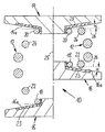
- the schematic drawing shows a helical compression spring, which is arranged as part of a suspension, not shown, of a motor vehicle between two spring supports.
- the left half of the drawing shows the helical compression spring in the rebound position and the right half of the helical compression spring in a partially rebounded position.
- the device 10 shown in longitudinal section has a barrel-shaped helical compression spring 12 which is clamped between two spring supports 14,16.
- the upper spring support 14 may, for example, be stationarily supported on the bodywork of the motor vehicle (not shown), while the lower spring support may be arranged on a handlebar or on a spring strut of a wheel suspension of the motor vehicle.
- the helical compression spring 12 (hereinafter referred to as the spring) or the position of the spring supports 14,16 drawn in the design position, d. H. in a defined middle position of the suspension, not shown.
- the second, larger diameter spring coils 22,24 and also the other spring coils are not on the spring supports 14,16, whereby defined suspension properties (comfortable, soft) are given.
- the spring 12 in the position shown in the right half of the drawing, so would in a conventional, the spring longitudinal axis 25 substantially vertical design of the bearing surfaces of the spring supports 14,16 (see, dashed line 26) the second Spring coils 22,24 already on the spring supports 14,16 abut and it would be the progression point (increase in spring rate with increasing gradient) already reached.
- the said progression point can be moved to any extent to some extent, in the z. B. spring supports 14,16 with different angles ⁇ of z. B. + 30 degrees (radially inwardly converging bearing surfaces 14 a, 16 a) to 0 degrees (perpendicular to the longitudinal axis 25) and from 0 degrees to - 30 degrees (radially inwardly diverging receiving surfaces 14 a, 16 a) and assigned after measurement of the springs 12 and be installed.
- the angle differences can each be 1 degree or more.
- the springs 12 are clamped in a test device (not shown) with receptacles conform to the spring supports 14,16, these recordings are provided with perpendicular to the spring longitudinal axis 25 shaped receiving surfaces.
- the spring 12 is clamped together and it is determined in a known manner, the force-displacement curve or determined from the kink-like increase in the characteristic progression point detected.
- About the traveled compression travel can now be determined either empirically or by appropriate calculation, which spring supports 14,16 are installed with which cone angles ⁇ with the measured spring 12. This ensures, independent of manufacturing tolerances on the springs 12, that the motor vehicle has a substantially uniform progression point of the springs 12 which is desired from the chassis tuning.
- the invention is not limited to the embodiment described.
- the spring supports 14,16 or their bearing surfaces 14a, 16a also coated, in particular galvanized, be executed. Possibly. can also be the spring coils 18,20 and / or 22,24 coated with a protective layer.
- cone-shaped support surfaces 14a, 16a it is also possible to use stepped support surfaces with corresponding transition regions on the spring supports 14, 16.
Landscapes
- Engineering & Computer Science (AREA)
- Mechanical Engineering (AREA)
- General Engineering & Computer Science (AREA)
- Springs (AREA)
- Vehicle Body Suspensions (AREA)
Description
- Die Erfindung betrifft eine Federanordnung, gemäß der im Oberbegriff des Patentanspruches 1 angegebenen Art.
- Insbesondere bei Radaufhängungen von Kraftfahrzeugen werden als Tragfedern häufig Schraubendruckfedern verwendet, die z. B. tonnenförmig ausgebildet sind und deshalb eine günstige progressive Kennung aufweisen. Nur beispielsweise wird auf die
DE 196 09 250 C2 verwiesen. - Für eine komfortable Abstimmung des Federverhaltens des Kraftfahrzeuges sollte dabei der Progressionspunkt-das ist der Moment, in dem eine weitere Federwindung der Schraubendruckfeder an der korrespondierenden Federauflage zur Anlage kommt und der bei einer Vermessung bei der Kraft-Weg-Kennlinie zu einem knickartigen Anstieg der Kennlinie führt - außerhalb des Federbereiches liegen, der beim Befahren normaler, ebener Fahrbahnen wirksam ist. Dann federt das Kraftfahrzeug im Komfortbereich (Landstraßen, Autobahn) bei Geradeausfahrt weich, hingegen nimmt bei zunehmender Einfederung z. B. bei Kurvenfahrt und entsprechender Querneigung des Kraftfahrzeuges die Federrate progressiv zu.
- Aufgrund von Fertigungstoleranzen, insbesondere der Schraubendruckfedern, liegt der besagte Progressionspunkt über den Einfederweg gesehen nicht immer gleich, so dass die gewünschte Abstimmung problematisch sein kann.
- In der
DE 36 25 101 A1 ist eine elastische Abstützung eines Fahrzeugrades an einer Kraftfahrzeugkarosserie offenbart. Die elastische Abstützung weist eine nichtlineare Schraubenfeder mit einem zylindrischen Abschnitt und wenigstens auf einer Seite daran angrenzend einen radial nach außen oder nach innen kegelstumpfförmigen Endbereich auf. Die Windungen des kegelstumpfförmigen Endbereiches stützen sich beim Einfedern nacheinander mit axialem Abstand nebeneinander liegend an der Mantelfläche eines kegelstumpfförmigen Federtellers ab. Die Mantelfläche des Federtellers ist etwa vom Durchmesser des zylindrischen Abschnittes der Schraubenfeder wie ihr kegelstumpfförmiger Endbereich radial nach außen oder nach innen, jedoch zur anderen Stirnseite der Schraubenfeder gerichtet. - Aus der
DE 24 59 207 A1 ist ein elastisches Lager bekannt, insbesondere zur Lagerung eines Motors am Fahrgestell eines Kraftfahrzeuges. Das elastische Lager wird durch eine Metallfeder in Form einer konischen Wendelfeder und durch eine gegebenenfalls mit Metalleinlagen verstärkte Dämpfungszwischenlage mit einem Dämpfungskörper aus elastomeren Material gebildet, an der das radial größere Ende der Metallfeder aufliegt. Die Dämpfungszwischenlage ist auflageseitig, z.B. am Fahrgestell, angeordnet und durch einen das Auflageende der Metallfeder festhaltenden Elastomerring gebildet. - Dieser ist in einem Gehäuse angeordnet und spannt die Metallfeder sowohl in radialer als auch in axialer Richtung fest. Der Dämpfungskörper weist einen sich nach oben konisch verjüngenden, innerhalb der Metallfeder liegenden Hubbegrenzungskörper auf, auf dass eine Halterung des Motors beim Einfedern auftrifft und elastisch abgedämpft wird. Die konische Mantelfläche liegt dabei nicht an der Feder an.
- Aufgabe der Erfindung ist es, eine Federanordnung gemäß der im Oberbegriff des Patentanspruches 1 angegebenen Art derart weiterzubilden, dass bei geringem Mehraufwand eine verbesserte Abstimmung der Federungseigenschaften erzielbar ist.
- Diese Aufgabe wird mit den kennzeichnenden Merkmalen des Patentanspruches 1 in Verbindung mit seinen Oberbegriffsmerkmalen gelöst.
- Die Unteransprüche bilden vorteilhafte Weiterbildungen der Erfindung.
- Nach der Erfindung ist die Auflagefläche der Federauflage als eine ebene Fläche ausgebildet, die schräg zur Federlängsachse verlaufend ausgerichtet ist und die Federauflage weist einen von der Endwindung umringten axialen Ansatz auf. Der besagte Progressionspunkt wird dadurch einheitlich nach einem definierten Einfederweg erreicht. Damit können vorteilhaft Fertigungstoleranzen der Schraubendruckfedern ausgeglichen und eine im wesentlichen einheitliche Federrate erzielt werden.
- Bevorzugt wird dabei so verfahren, dass die jeweilige Schraubendruckfeder vor deren Einbau z. B. in eine Radaufhängung eines Kraftfahrzeuges in einer Prüfvorrichtung mit neutralen Federauflagen vorgespannt und deren Kraft-Weg-Kennlinie ermittelt wird. Liegt der Progressionspunkt der betreffenden Feder hinsichtlich des Einfederweges zu früh oder zu spät, so werden entweder durch empirische Ermittlung oder durch Berechnung wie hinsichtlich ihrer Auflageflächen unterschiedlichen Federauflagen entsprechend zugeordnet. Erst dann werden die Schraubendruckfedern jeweils mit den zugeordneten Federauflagen in die Radaufhängung bzw. in das Kraftfahrzeug eingebaut.
- Die Federauflagen sind mit zumindest zwei Auflageflächen für die Endwindung der Feder und für die zumindest zweite Federwindung unterschiedlich ausgebildet, in dem diese höhenversetzt zueinander sind. Damit wird quasi der Einsatzpunkt (= Progressionspunkt) der zweiten Federwindung der Schraubendruckfeder auf ein einheitliches Federungsverhalten abgestimmt. Der Versatz kann dabei in beiden Richtungen von z. B. + 10 mm bis gegen 0 und - 10 mm betragen.
- Bevorzugt ist die Federauflage schräg zur Federmittelachse verlaufend geneigt bzw. bei einer rotationssymmetrischen Federauflage konisch. Der Konuswinkel α kann zwischen + oder - 30 Grad betragen.
- Die Federauflagen können in an sich bekannter Weise einen elastischen Dämpfungsring aus Gummi oder Kunststoff tragen. Die Federauflagen können jedoch auch zur Vermeidung von Kontaktkorrosion mit einer schützenden Beschichtung versehen sein, z. B. durch Verzinken.
- Ein Ausführungsbeispiel der Erfindung ist im folgenden mit weiteren Einzelheiten näher erläutert. Die schematische Zeichnung zeigt eine Schraubendruckfeder, die als Teil einer nicht dargestellten Radaufhängung eines Kraftfahrzeuges zwischen zwei Federauflagen angeordnet ist. Dabei zeigt die linke Hälfte der Zeichnung die Schraubendruckfeder in der ausgefederten Position und die rechte Hälfte die Schraubendruckfeder in einer teilweise eingefederten Position.
- Die im Längsschnitt dargestellte Vorrichtung 10 weist eine tonnenförmige Schraubendruckfeder 12 auf, die zwischen zwei Federauflagen 14,16 eingespannt ist.
- Dabei liegt die jeweils im Durchmesser verringerte Endwindung 18,20 unter Zwischenlage eines elastomeren Dämpfungsringes 23 an der Federauflage 14,16 an.
- Die obere Federauflage 14 kann beispielsweise an der Karosserie des Kraftfahrzeuges (nicht dargestellt) ortsfest abgestützt sein, während die untere Federauflage an einem Lenker oder an einem Federbein einer Radaufhängung des Kraftfahrzeuges angeordnet sein kann.
- In der linken Zeichnungshälfte ist die Schraubendruckfeder 12 (im weiteren als Feder bezeichnet) bzw. die Position der Federauflagen 14,16 in Konstruktionslage gezeichnet, d. h. in einer definierten Mittelstellung der nicht dargestellten Radaufhängung. Dabei liegen die jeweils zweiten, im Durchmesser größeren Federwindungen 22,24 und auch die weiteren Federwindungen nicht an den Federauflagen 14,16 an, wodurch definierte Federungseigenschaften (komfortabel, weich) gegeben sind.
- Wird durch eine entsprechende Belastung bzw. Einfederung die Feder 12 in die in der rechten Zeichnungshälfte dargestellte Position vorgespannt, so würden bei einer üblichen, zur Federlängsachse 25 im wesentlichen senkrechten Gestaltung der Auflageflächen der Federauflagen 14,16 (vgl. gestrichelte Linie 26) die zweiten Federwindungen 22,24 bereits an den Federauflagen 14,16 anliegen und es wäre der Progressionspunkt (Anstieg der Federrate mit zunehmendem Gradienten) bereits erreicht.
- Durch die konische Gestaltung der Federauflagen 14,16 und der Dämpfungsringe 23 unter dem Winkel α ergeben sich zur Senkrechten 26 schräge Auflageflächen 14a,16a, die den besagten Progressionspunkt wie ersichtlich auf eine geringere Höhe (Abstand der beiden Federauflagen 14,16 zueinander) verschieben.
- Durch Variation der Winkel α an zumindest einer der Federauflagen 14,16, bevorzugt jedoch an beiden, kann der besagte Progressionspunkt in gewissem Ausmaß beliebig verschoben werden, in dem z. B. Federauflagen 14,16 mit unterschiedlichen Winkeln α von z. B. + 30 Grad (radial nach innen konvergierende Auflageflächen 14a,16a) bis 0 Grad (Senkrechte zur Längsachse 25) und von 0 Grad bis - 30 Grad (radial nach innen divergierende Aufnahmeflächen 14a,16a) bereitgestellt und nach Vermessung der Federn 12 zugeordnet und verbaut werden. Die Winkeldifferenzen können dabei jeweils 1 Grad oder mehr betragen.
- Die Federn 12 werden in eine Prüfvorrichtung (nicht dargestellt) mit Aufnahmen konform den Federauflagen 14,16 eingespannt, wobei diese Aufnahmen mit senkrecht zur Federlängsachse 25 gestalteten Aufnahmeflächen versehen sind.
- Danach wird die Feder 12 zusammengespannt und es wird in bekannter Weise die Kraft-Weg-Kennlinie ermittelt bzw. der aus dem knickartigem Anstieg der Kennlinie erkennbare Progressionspunkt festgestellt. Über den zurückgelegten Einfederweg kann nun entweder empirisch oder durch entsprechende Berechnung festgelegt werden, welche Federauflagen 14,16 mit welchen Konuswinkeln α mit der vermessenen Feder 12 zu verbauen sind. Dies stellt unabhängig von Fertigungstoleranzen an den Federn 12 sicher, dass am Kraftfahrzeug ein im wesentlichen einheitlicher und von der Fahrwerksabstimmung her erwünschter Progressionspunkt der Federn 12 vorliegt.
- Die Erfindung ist nicht auf das beschriebene Ausführungsbeispiel beschränkt. So können anstelle der Dämpfungsringe 22 die Federauflagen 14,16 bzw. deren Auflageflächen 14a,16a auch beschichtet, insbesondere verzinkt, ausgeführt sein. Ggf. können auch die Federwindungen 18,20 und/oder 22,24 mit einer Schutzschicht überzogen sein. An Stelle konusförmiger Auflageflächen 14a,16a können auch gestufte Auflageflächen mit entsprechenden Übergansbereichen an den Federauflagen 14,16 verwendet sein.
Claims (8)
- Federanordnung mit einer Schraubendruckfeder (12) und mit zumindest einer Federauflage (14, 16) mit einer Auflagefläche (14a, 16a), an der die Schraubendruckfeder (12) mit einer Endwindung (18, 20) stirnseitig anliegt und beim Zusammendrücken der Schraubendruckfeder (12) zumindest eine weitere Federwindung (22, 24) zur Anlage kommt, insbesondere für Radaufhängungen in Kraftfahrzeugen, dadurch gekennzeichnet, dass die Auflagefläche (14a, 16a) der Federauflage (14, 16) als eine ebene Fläche ausgebildet ist, die schräg zur Federlängsachse (25) verlaufend ausgerichtet ist und dass die Federauflage (14, 16) einen von der Endwindung (18, 20) umringten axialen Ansatz aufweist.
- Federanordnung nach Anspruch 1, dadurch gekennzeichnet, dass die Schraubendruckfeder (12) tonnenförmig ausgebildet ist und der Schraubendruckfeder (12) zwei Federauflagen (14, 16) zugeordnet sind.
- Federanordnung nach den Ansprüchen 1 und 2, dadurch gekennzeichnet, dass die Endwindung (18, 20) einen kleineren Drahtdurchmesser aufweist als die weitere Federwindung (22, 24) .
- Federanordnung nach einem der Ansprüche 1 bis 3, dadurch gekennzeichnet, dass die Federauflagefläche (14a, 16a) konisch gestaltet ist.
- Federanordnung nach Anspruch 4, dadurch gekennzeichnet, dass der Konuswinkel zwischen bis +30 Grad oder -30 Grad beträgt.
- Federanordnung nach einem der vorhergehenden Ansprüche, dadurch gekennzeichnet, dass die Federauflage (14,16) korrosionsgeschützt beschichtet, insbesondere verzinkt ist.
- Federanordnung nach einem der vorhergehenden Ansprüche, dadurch gekennzeichnet, dass die Federauflage (14,16) im Bereich der Auflageflächen (14a,16a) einen Dämpfungsring (23) aus elastomeren Material trägt.
- Federanordnung nach einem der vorhergehenden Ansprüche, dadurch gekennzeichnet, dass am anderen Ende der Schraubendruckfeder (12) eine Federauflage (14,16) entsprechend spiegelbildlich Ausgestaltung angeordnet ist.
Applications Claiming Priority (3)
| Application Number | Priority Date | Filing Date | Title |
|---|---|---|---|
| DE10132991A DE10132991C2 (de) | 2001-07-06 | 2001-07-06 | Federanordnung |
| DE10132991 | 2001-07-06 | ||
| PCT/EP2002/005132 WO2003004900A1 (de) | 2001-07-06 | 2002-05-10 | Verfahren zum anordnen einer schraubendruckfeder |
Publications (2)
| Publication Number | Publication Date |
|---|---|
| EP1407164A1 EP1407164A1 (de) | 2004-04-14 |
| EP1407164B1 true EP1407164B1 (de) | 2008-09-03 |
Family
ID=7690963
Family Applications (1)
| Application Number | Title | Priority Date | Filing Date |
|---|---|---|---|
| EP02750912A Expired - Lifetime EP1407164B1 (de) | 2001-07-06 | 2002-05-10 | Federanordnung |
Country Status (5)
| Country | Link |
|---|---|
| EP (1) | EP1407164B1 (de) |
| AT (1) | ATE407303T1 (de) |
| DE (2) | DE10132991C2 (de) |
| ES (1) | ES2309186T3 (de) |
| WO (1) | WO2003004900A1 (de) |
Citations (2)
| Publication number | Priority date | Publication date | Assignee | Title |
|---|---|---|---|---|
| DE2459207A1 (de) * | 1974-12-14 | 1976-06-16 | Daimler Benz Ag | Elastisches lager |
| DE3625101A1 (de) * | 1986-07-24 | 1988-02-04 | Bayerische Motoren Werke Ag | Elastische abstuetzung eines fahrzeugrades an der karosserie |
Family Cites Families (5)
| Publication number | Priority date | Publication date | Assignee | Title |
|---|---|---|---|---|
| DE2932500A1 (de) * | 1979-08-10 | 1981-02-12 | Hoesch Estel Werke Ag | Federteller fuer schraubendruckfedern |
| DE3728462A1 (de) * | 1986-09-03 | 1988-03-10 | Volkswagen Ag | Schraubendruckfeder einer kraftfahrzeugfederung |
| DE19609250C2 (de) * | 1996-03-09 | 2001-04-05 | Opel Adam Ag | Elastische Federendauflage, insbesondere für eine tonnenförmig gewickelte Feder einer Kraftfahrzeugachse |
| DE19939515C2 (de) * | 1999-08-20 | 2002-06-13 | Porsche Ag | Federbein für ein Kraftfahrzeug mit einer Lagerung für eine Schraubenfeder |
| US6481702B1 (en) * | 2000-09-20 | 2002-11-19 | Meritor Heavy Vehicle Systems, Llc | Reduction of coil spring load height variability |
-
2001
- 2001-07-06 DE DE10132991A patent/DE10132991C2/de not_active Expired - Fee Related
-
2002
- 2002-05-10 EP EP02750912A patent/EP1407164B1/de not_active Expired - Lifetime
- 2002-05-10 AT AT02750912T patent/ATE407303T1/de not_active IP Right Cessation
- 2002-05-10 WO PCT/EP2002/005132 patent/WO2003004900A1/de not_active Ceased
- 2002-05-10 ES ES02750912T patent/ES2309186T3/es not_active Expired - Lifetime
- 2002-05-10 DE DE50212731T patent/DE50212731D1/de not_active Expired - Lifetime
Patent Citations (2)
| Publication number | Priority date | Publication date | Assignee | Title |
|---|---|---|---|---|
| DE2459207A1 (de) * | 1974-12-14 | 1976-06-16 | Daimler Benz Ag | Elastisches lager |
| DE3625101A1 (de) * | 1986-07-24 | 1988-02-04 | Bayerische Motoren Werke Ag | Elastische abstuetzung eines fahrzeugrades an der karosserie |
Also Published As
| Publication number | Publication date |
|---|---|
| ATE407303T1 (de) | 2008-09-15 |
| DE10132991C2 (de) | 2003-09-25 |
| DE10132991A1 (de) | 2003-01-30 |
| EP1407164A1 (de) | 2004-04-14 |
| WO2003004900A1 (de) | 2003-01-16 |
| DE50212731D1 (de) | 2008-10-16 |
| ES2309186T3 (es) | 2008-12-16 |
Similar Documents
| Publication | Publication Date | Title |
|---|---|---|
| EP0302180B1 (de) | Gelenk für Achsstreben, Lenker oder dergleichen in Kraftfahrzeugen | |
| DE102010036680A1 (de) | Aufhängungsarm und Verfahren zur Herstellung desselben | |
| WO1998026947A1 (de) | Luftfedersystem | |
| EP0816140A1 (de) | Oberes Federbeinstützlager für Radaufhängungen in einem Kraftfahrzeug | |
| DE102009027319A1 (de) | Elastische Buchse | |
| DE19717892A1 (de) | Luftfeder | |
| DE69905548T3 (de) | Radaufhängungssystem und dazu passende feder | |
| DE102009047404A1 (de) | Radaufhängung | |
| EP2905503A2 (de) | Elastomer-Lagerbuchse, insbesondere zur Lagerung eines Stoßdämpfers einer Fahrzeug-Achsanbindung | |
| DE102012213905A1 (de) | Federteller | |
| WO2011095242A1 (de) | Luftfedereinrichtung eines schienenfahrzeuges | |
| DE3204816A1 (de) | Oberes verankerungssystem fuer ein federbein einer mcpherson-aufhaengung | |
| EP2186661B1 (de) | Veränderbare Abstützung einer Schraubendruckfeder oder dergleichen für ein Kraftfahrzeug | |
| EP1878937B1 (de) | Elastisches Fahrwerkslager | |
| DE102005015089B4 (de) | Radaufhängung für ein Fahrzeug | |
| DE4007488A1 (de) | Federbein fuer fahrzeuge | |
| DE102017011347A1 (de) | Obere stütze | |
| EP1118791B1 (de) | Elastomer-Metall-Gelenkbuchse | |
| DE10132991C2 (de) | Federanordnung | |
| EP1371872B1 (de) | Luftfederanordnung | |
| EP0450576B1 (de) | Karosserieseitige Lagerung eines Federbeins sowie Verfahren zur Herstellung einer solchen Lagerung | |
| EP1878597A2 (de) | Lenkeranordnung | |
| DE102021107800A1 (de) | Achse eines Fahrzeuges | |
| DE102007038072A1 (de) | Radaufhängung | |
| DE10134107B4 (de) | Lenker für eine Radaufhängung in Kraftfahrzeugen |
Legal Events
| Date | Code | Title | Description |
|---|---|---|---|
| PUAI | Public reference made under article 153(3) epc to a published international application that has entered the european phase |
Free format text: ORIGINAL CODE: 0009012 |
|
| 17P | Request for examination filed |
Effective date: 20030911 |
|
| AK | Designated contracting states |
Kind code of ref document: A1 Designated state(s): AT BE CH CY DE DK ES FI FR GB GR IE IT LI LU MC NL PT SE TR |
|
| 17Q | First examination report despatched |
Effective date: 20070118 |
|
| GRAP | Despatch of communication of intention to grant a patent |
Free format text: ORIGINAL CODE: EPIDOSNIGR1 |
|
| RTI1 | Title (correction) |
Free format text: SPRING ARRANGEMENT |
|
| GRAS | Grant fee paid |
Free format text: ORIGINAL CODE: EPIDOSNIGR3 |
|
| GRAA | (expected) grant |
Free format text: ORIGINAL CODE: 0009210 |
|
| AK | Designated contracting states |
Kind code of ref document: B1 Designated state(s): AT BE CH CY DE DK ES FI FR GB GR IE IT LI LU MC NL PT SE TR |
|
| REG | Reference to a national code |
Ref country code: GB Ref legal event code: FG4D Free format text: NOT ENGLISH |
|
| REG | Reference to a national code |
Ref country code: CH Ref legal event code: EP |
|
| REG | Reference to a national code |
Ref country code: IE Ref legal event code: FG4D Free format text: LANGUAGE OF EP DOCUMENT: GERMAN |
|
| REF | Corresponds to: |
Ref document number: 50212731 Country of ref document: DE Date of ref document: 20081016 Kind code of ref document: P |
|
| REG | Reference to a national code |
Ref country code: ES Ref legal event code: FG2A Ref document number: 2309186 Country of ref document: ES Kind code of ref document: T3 |
|
| PG25 | Lapsed in a contracting state [announced via postgrant information from national office to epo] |
Ref country code: NL Free format text: LAPSE BECAUSE OF FAILURE TO SUBMIT A TRANSLATION OF THE DESCRIPTION OR TO PAY THE FEE WITHIN THE PRESCRIBED TIME-LIMIT Effective date: 20080903 |
|
| PG25 | Lapsed in a contracting state [announced via postgrant information from national office to epo] |
Ref country code: FI Free format text: LAPSE BECAUSE OF FAILURE TO SUBMIT A TRANSLATION OF THE DESCRIPTION OR TO PAY THE FEE WITHIN THE PRESCRIBED TIME-LIMIT Effective date: 20080903 |
|
| NLV1 | Nl: lapsed or annulled due to failure to fulfill the requirements of art. 29p and 29m of the patents act | ||
| REG | Reference to a national code |
Ref country code: IE Ref legal event code: FD4D |
|
| PG25 | Lapsed in a contracting state [announced via postgrant information from national office to epo] |
Ref country code: IE Free format text: LAPSE BECAUSE OF FAILURE TO SUBMIT A TRANSLATION OF THE DESCRIPTION OR TO PAY THE FEE WITHIN THE PRESCRIBED TIME-LIMIT Effective date: 20080903 |
|
| PG25 | Lapsed in a contracting state [announced via postgrant information from national office to epo] |
Ref country code: PT Free format text: LAPSE BECAUSE OF FAILURE TO SUBMIT A TRANSLATION OF THE DESCRIPTION OR TO PAY THE FEE WITHIN THE PRESCRIBED TIME-LIMIT Effective date: 20090203 |
|
| PLBE | No opposition filed within time limit |
Free format text: ORIGINAL CODE: 0009261 |
|
| STAA | Information on the status of an ep patent application or granted ep patent |
Free format text: STATUS: NO OPPOSITION FILED WITHIN TIME LIMIT |
|
| PG25 | Lapsed in a contracting state [announced via postgrant information from national office to epo] |
Ref country code: DK Free format text: LAPSE BECAUSE OF FAILURE TO SUBMIT A TRANSLATION OF THE DESCRIPTION OR TO PAY THE FEE WITHIN THE PRESCRIBED TIME-LIMIT Effective date: 20080903 |
|
| 26N | No opposition filed |
Effective date: 20090604 |
|
| BERE | Be: lapsed |
Owner name: AUDI A.G. Effective date: 20090531 |
|
| PG25 | Lapsed in a contracting state [announced via postgrant information from national office to epo] |
Ref country code: MC Free format text: LAPSE BECAUSE OF NON-PAYMENT OF DUE FEES Effective date: 20090531 |
|
| REG | Reference to a national code |
Ref country code: CH Ref legal event code: PL |
|
| PG25 | Lapsed in a contracting state [announced via postgrant information from national office to epo] |
Ref country code: SE Free format text: LAPSE BECAUSE OF FAILURE TO SUBMIT A TRANSLATION OF THE DESCRIPTION OR TO PAY THE FEE WITHIN THE PRESCRIBED TIME-LIMIT Effective date: 20081203 Ref country code: LI Free format text: LAPSE BECAUSE OF NON-PAYMENT OF DUE FEES Effective date: 20090531 Ref country code: CH Free format text: LAPSE BECAUSE OF NON-PAYMENT OF DUE FEES Effective date: 20090531 |
|
| PG25 | Lapsed in a contracting state [announced via postgrant information from national office to epo] |
Ref country code: BE Free format text: LAPSE BECAUSE OF NON-PAYMENT OF DUE FEES Effective date: 20090531 |
|
| PG25 | Lapsed in a contracting state [announced via postgrant information from national office to epo] |
Ref country code: AT Free format text: LAPSE BECAUSE OF NON-PAYMENT OF DUE FEES Effective date: 20090510 |
|
| PG25 | Lapsed in a contracting state [announced via postgrant information from national office to epo] |
Ref country code: GR Free format text: LAPSE BECAUSE OF FAILURE TO SUBMIT A TRANSLATION OF THE DESCRIPTION OR TO PAY THE FEE WITHIN THE PRESCRIBED TIME-LIMIT Effective date: 20081204 |
|
| PG25 | Lapsed in a contracting state [announced via postgrant information from national office to epo] |
Ref country code: LU Free format text: LAPSE BECAUSE OF NON-PAYMENT OF DUE FEES Effective date: 20090510 |
|
| PG25 | Lapsed in a contracting state [announced via postgrant information from national office to epo] |
Ref country code: TR Free format text: LAPSE BECAUSE OF FAILURE TO SUBMIT A TRANSLATION OF THE DESCRIPTION OR TO PAY THE FEE WITHIN THE PRESCRIBED TIME-LIMIT Effective date: 20080903 |
|
| PG25 | Lapsed in a contracting state [announced via postgrant information from national office to epo] |
Ref country code: CY Free format text: LAPSE BECAUSE OF FAILURE TO SUBMIT A TRANSLATION OF THE DESCRIPTION OR TO PAY THE FEE WITHIN THE PRESCRIBED TIME-LIMIT Effective date: 20080903 |
|
| REG | Reference to a national code |
Ref country code: DE Ref legal event code: R084 Ref document number: 50212731 Country of ref document: DE Effective date: 20120310 |
|
| REG | Reference to a national code |
Ref country code: FR Ref legal event code: PLFP Year of fee payment: 14 |
|
| PGFP | Annual fee paid to national office [announced via postgrant information from national office to epo] |
Ref country code: ES Payment date: 20150511 Year of fee payment: 14 Ref country code: DE Payment date: 20150531 Year of fee payment: 14 Ref country code: GB Payment date: 20150518 Year of fee payment: 14 |
|
| PGFP | Annual fee paid to national office [announced via postgrant information from national office to epo] |
Ref country code: IT Payment date: 20150527 Year of fee payment: 14 Ref country code: FR Payment date: 20150518 Year of fee payment: 14 |
|
| REG | Reference to a national code |
Ref country code: DE Ref legal event code: R119 Ref document number: 50212731 Country of ref document: DE |
|
| GBPC | Gb: european patent ceased through non-payment of renewal fee |
Effective date: 20160510 |
|
| PG25 | Lapsed in a contracting state [announced via postgrant information from national office to epo] |
Ref country code: IT Free format text: LAPSE BECAUSE OF NON-PAYMENT OF DUE FEES Effective date: 20160510 |
|
| REG | Reference to a national code |
Ref country code: FR Ref legal event code: ST Effective date: 20170131 |
|
| PG25 | Lapsed in a contracting state [announced via postgrant information from national office to epo] |
Ref country code: DE Free format text: LAPSE BECAUSE OF NON-PAYMENT OF DUE FEES Effective date: 20161201 Ref country code: FR Free format text: LAPSE BECAUSE OF NON-PAYMENT OF DUE FEES Effective date: 20160531 |
|
| PG25 | Lapsed in a contracting state [announced via postgrant information from national office to epo] |
Ref country code: GB Free format text: LAPSE BECAUSE OF NON-PAYMENT OF DUE FEES Effective date: 20160510 |
|
| PG25 | Lapsed in a contracting state [announced via postgrant information from national office to epo] |
Ref country code: ES Free format text: LAPSE BECAUSE OF NON-PAYMENT OF DUE FEES Effective date: 20160511 |
|
| REG | Reference to a national code |
Ref country code: ES Ref legal event code: FD2A Effective date: 20180626 |