EP1406692B1 - Ensemble électrode/traversée pour la détection sous-cutanée - Google Patents
Ensemble électrode/traversée pour la détection sous-cutanée Download PDFInfo
- Publication number
- EP1406692B1 EP1406692B1 EP02725315A EP02725315A EP1406692B1 EP 1406692 B1 EP1406692 B1 EP 1406692B1 EP 02725315 A EP02725315 A EP 02725315A EP 02725315 A EP02725315 A EP 02725315A EP 1406692 B1 EP1406692 B1 EP 1406692B1
- Authority
- EP
- European Patent Office
- Prior art keywords
- ferrule
- imd
- feedthrough
- electrode
- housing
- Prior art date
- Legal status (The legal status is an assumption and is not a legal conclusion. Google has not performed a legal analysis and makes no representation as to the accuracy of the status listed.)
- Expired - Lifetime
Links
- VDOUPCGIPZNLIY-UHFFFAOYSA-N O=NC1=CC=CC1 Chemical compound O=NC1=CC=CC1 VDOUPCGIPZNLIY-UHFFFAOYSA-N 0.000 description 1
Images


Classifications
-
- A—HUMAN NECESSITIES
- A61—MEDICAL OR VETERINARY SCIENCE; HYGIENE
- A61N—ELECTROTHERAPY; MAGNETOTHERAPY; RADIATION THERAPY; ULTRASOUND THERAPY
- A61N1/00—Electrotherapy; Circuits therefor
- A61N1/18—Applying electric currents by contact electrodes
- A61N1/32—Applying electric currents by contact electrodes alternating or intermittent currents
- A61N1/36—Applying electric currents by contact electrodes alternating or intermittent currents for stimulation
- A61N1/372—Arrangements in connection with the implantation of stimulators
- A61N1/378—Electrical supply
-
- A—HUMAN NECESSITIES
- A61—MEDICAL OR VETERINARY SCIENCE; HYGIENE
- A61N—ELECTROTHERAPY; MAGNETOTHERAPY; RADIATION THERAPY; ULTRASOUND THERAPY
- A61N1/00—Electrotherapy; Circuits therefor
- A61N1/18—Applying electric currents by contact electrodes
- A61N1/32—Applying electric currents by contact electrodes alternating or intermittent currents
- A61N1/36—Applying electric currents by contact electrodes alternating or intermittent currents for stimulation
- A61N1/372—Arrangements in connection with the implantation of stimulators
- A61N1/375—Constructional arrangements, e.g. casings
- A61N1/3752—Details of casing-lead connections
- A61N1/3754—Feedthroughs
-
- A—HUMAN NECESSITIES
- A61—MEDICAL OR VETERINARY SCIENCE; HYGIENE
- A61N—ELECTROTHERAPY; MAGNETOTHERAPY; RADIATION THERAPY; ULTRASOUND THERAPY
- A61N1/00—Electrotherapy; Circuits therefor
- A61N1/18—Applying electric currents by contact electrodes
- A61N1/32—Applying electric currents by contact electrodes alternating or intermittent currents
- A61N1/36—Applying electric currents by contact electrodes alternating or intermittent currents for stimulation
- A61N1/372—Arrangements in connection with the implantation of stimulators
- A61N1/375—Constructional arrangements, e.g. casings
- A61N1/3756—Casings with electrodes thereon, e.g. leadless stimulators
-
- Y—GENERAL TAGGING OF NEW TECHNOLOGICAL DEVELOPMENTS; GENERAL TAGGING OF CROSS-SECTIONAL TECHNOLOGIES SPANNING OVER SEVERAL SECTIONS OF THE IPC; TECHNICAL SUBJECTS COVERED BY FORMER USPC CROSS-REFERENCE ART COLLECTIONS [XRACs] AND DIGESTS
- Y02—TECHNOLOGIES OR APPLICATIONS FOR MITIGATION OR ADAPTATION AGAINST CLIMATE CHANGE
- Y02E—REDUCTION OF GREENHOUSE GAS [GHG] EMISSIONS, RELATED TO ENERGY GENERATION, TRANSMISSION OR DISTRIBUTION
- Y02E60/00—Enabling technologies; Technologies with a potential or indirect contribution to GHG emissions mitigation
- Y02E60/10—Energy storage using batteries
Definitions
- the present invention relates generally to implantable pacemakers and more particularly to subcutaneous electrodes implemented to sense, acquire, and store electrocardiographic data and waveform tracings from an implanted pacemaker. More particularly, the present invention relates to various embodiments including the manufacture and assembly of such electrodes with feedthroughs that facilitate their electrical connection to a pacemaker's circuitry.
- Electrocardiogram (ECG) signals are commonly used in medicine to determine the status of the electrical conduction system of the human heart.
- ECG Electrocardiogram
- an ECG recording device is commonly attached to the patient via ECG leads connected to skin electrodes arrayed on the patient's body so as to achieve a recording that displays the cardiac waveforms in any one of 12 possible vectors.
- implantable IMD technology Since the implantation of the first cardiac pacemaker, implantable IMD technology has advanced with the development of sophisticated, programmable cardiac pacemakers and pacemaker-cardioverter-defibrillator (PCD) arrhythmia control devices designed to detect arrhythmias and dispense appropriate therapies. The detection and discrimination between various arrhythmic episodes in order to trigger the delivery of an appropriate therapy is of considerable interest.
- Prescription for implantation and programming of the implanted device are based on the analysis of the PQRST electrocardiogram (ECG) and the electrogram (EGM). The waveforms are usually separated for such analysis into the P-wave and R-wave in systems that are designed to detect the depolarization of the atrium and ventricle respectively.
- Such systems employ detection of the occurrence of the P-wave and R-wave, analysis of the rate, regularity, and onset of variations in the rate of recurrence of the P-wave and R-wave, the morphology of the P-wave and R-wave and the direction of propagation of the depolarization represented by the P-wave and R-wave in the heart.
- the detection, analysis and storage of such EGM data within implanted medical devices are well known in the art.
- Acquisition and use of ECG tracing(s) has generally been limited to the use of an external ECG recording machine attached to the patient via surface electrodes of one sort or another.
- the aforementioned ECG systems that use detection and analysis of the PQRST complex are all dependent upon the spatial orientation and number of externally applied electrodes available near or around the heart to detect or sense the cardiac depolarization wave front.
- implantable medical device systems As the functional sophistication and complexity of implantable medical device systems increased over the years, it has become necessary for such systems to include communication means between implanted devices and/or an external device, for example, a programming console, monitoring system, and similar systems. For diagnostic purposes, it is desirable that the implanted device be able to communicate information regarding the device's operational status and the patient's condition to the physician or clinician.
- implantable devices are available which can transmit or telemeter a digitized electrical signal to display electrical cardiac activity (e.g., an ECG, EGM, or the like) for storage and/or analysis by an external device.
- the twelve-lead electrocardiogram is generally the first procedure used to determine cardiac status prior to implanting a pacing system. Thereafter, the physician will typically use an ECG available through the programmer or extra corporeal telemetry transmission to check the pacemaker's efficacy after implantation.
- ECG tracings are placed into the patient's records for later use in comparing against more recent tracings. It must be noted, however, that current art practice in ECG recording (whether through a direct connection to an ECG recording device or to a pacemaker programmer), involves the use of external ECG electrodes and leads.
- Electrodes attached externally to the body are a major source of signal quality problems and errors because of susceptibility to interference such as muscle noise, electromagnetic interference, high frequency communication equipment interference, and baseline shift from respiration, for example. Signal degradation also occurs due to contact problems, ECG waveform artifacts, and patient discomfort. Externally attached electrodes are also subject to motion artifacts from positional changes and the relative displacement between the skin and the electrodes. Furthermore, external electrodes require special skin preparation, for example, application of electrolyte ointment or cream, to ensure adequate electrical contact.
- Such preparation, along with positioning the electrode and attachment of the ECG lead to the electrode needlessly prolongs the pacemaker follow-up session.
- One possible approach is to equip the implanted pacemaker with features for detecting cardiac signals and transforming them into a tracing that is the same as or comparable to tracings obtainable via ECG leads attached to surface (skin) electrodes.
- U.S. Pat. No. 4,310,000 to Lindemans and U.S. Pat. Nos. 4,729,376 and 4,674,508 to DeCote disclose the use of a separate passive sensing reference electrode mounted on the pacemaker connector block or otherwise insulated from the pacemaker case.
- the passive electrode is implemented to provide a sensing reference electrode that is not part of the stimulation reference electrode and thus does not carry residual after-potentials at its surface following delivery of a stimulation pulse.
- U.S. Pat. No. 5,33 1,966 to Bennett discloses a method and apparatus for providing an enhanced capability of detecting and gathering electrical cardiac signals via an array of relatively closely spaced subcutaneous electrodes (located on the body of an implanted device).
- US patent no. 6,522,915 B1 discloses an alternate method and apparatus for detecting electrical cardiac signals via an array of subcutaneous electrodes located on a shroud circumferentially placed on the perimeter of an implanted pacemaker.
- An associated submission, Subcutaneous Etectrode for Sensing Electrical Signals of the Heart by Brabec et al, filed on October 31, 2000, US 6,512,940 B1 discloses the use of a spiral electrode implemented in conjunction with the shroud described in US patent no. 6,522,915 B1 .
- Multilayer Ceramic Electrodes for Sensing Cardiac Depolarization Signals filed October 25, 2000, US 6,631,290 B1
- Thin Film Electrodes for Sensing Cardiac Depolarization Signals filed on December 13, 2000, US 2002/0072778 A1, both by Gluck et al , disclose the use of multi-layer ceramic and thin film ECG electrodes placed into recesses incorporated a long and into the peripheral edge of the implantable pacemaker.
- the present invention relates to various electrode designs that allow direct incorporation of the electrode into a feedthrough.
- the feedthrough ferrules may be welded individually into desired positions around the perimeter of an implantable pacemaker and then the feedthrough/electrodes fabricated into the existing ferrules.
- the complete feedthrough/electrode assembly may be fabricated and then welded as one body into the pacemaker.
- These feedthrough/electrode assemblies are electrically connected to the circuitry of an implantable pacemaker to create a leadless Subcutaneous Electrode Array (SEA) for the purpose of detecting cardiac depolarization waveforms displayable as electrocardiographic tracings on an external device in communication with the pacemaker.
- SEA Subcutaneous Electrode Array
- an implanted device equipped with a leadless SEA electrocardiographic tracing waveforms may be displayed and viewed on the programmer screen. These waveforms may also be telemetered extra-corporeally to an external device located nearby or at some distance from the patient, as is described in Leadless Fully Automatic Pacemaker Follow-Up by Combs and Berg, filed on December 27, 2000, US 6,584,352 B2 .
- the present invention may be a replacement for externally mounted electrodes and electrode wires in the prior art currently used on the leadless ECG implantable pacemaker, as described in U.S. Pat. No. 5,331,966 issued to Bennett .
- prior art practice includes electrodes placed on the face of the implanted pacemaker. When facing muscle, the electrodes are apt to detect myopotentials and are susceptible to baseline drift.
- the present invention minimizes myopotential detection and thereby makes the pacemaker less sensitive to orientation in the incision pocket of a patient. Further, allowing the device to be implanted on either side of the chest provides maximum electrode separation and minimal signal variation. This is primarily because of variations in pacemaker orientations within the pocket. Implantable device electrodes need to be placed on the perimeter of the pacemaker in such a way as to maximize the distance between electrode pairs.
- the present invention eliminates the need for a compliant shroud that typically houses the surface mounted electrodes and connecting wires as described in Patent application No. P-9033, " Surround Shroud Connector And Electrode Housings For A Subcutaneous Electrode Array And Leadless ECGs," by Ceballos et al. filed on October 26, 2000, US 6,522,915 B1 . Because the feedthrough/electrode assembly is an integral functional component, the complete assembly can be welded directly into the IPG casing.
- the present invention, including the manufacturing process disclosed herein eliminate the need for a compliant shroud in addition to structural efficiencies and ease of handling of the implantable pacemaker during the implant procedure.
- the spacing of the electrodes in the present invention provides maximal electrode spacing, minimal myopotential electrical noise, and, at the same time, appropriate insulation from the pacemaker casing particularly because of the welding of the assemblies to the pacemaker casing.
- the electrode spacing around the pacemaker's perimeter preferably maintains a maximum and equal distance between the electrode pairs. Spacing arrangements such as disclosed with the three-electrode equal spacing embodiment maintain a maximum average signal. The arrangement is preferred because the spacing of the three vectors between the electrode pairs is equal and the angle between the vectors is equilateral, as is shown using mathematical modeling. Such an arrangement of electrode pairs also minimizes signal variation.
- An alternate three-electrode embodiment includes electrodes arranged so that the spacing of two vectors is equal and the -angle between them set at 90°. Vectors in these embodiments can be combined to provide adequate sensing of cardiac signals (ECGs). Further disclosure of the position of three and four-electrodes in the Subcutaneous Electrode Array (SEA) may be found in ECGs). Further disclosure of the position
- the present invention allows a physician or medical technician to perform leadless follow-up that, in turn, eliminates the time it takes to attach external leads to the patient. Such timesavings may significantly reduce the cost of follow-up, and may enable the physician or medical technician to see more patients.
- Other implementations include, but are not limited to: Holter monitoring with event storage, arrhythmia detection and monitoring, capture detection, ischemia detection and monitoring (S-T elevation and suppression on the ECG), changes in QT interval, and transtelephonic and telemetric monitoring.
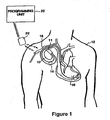
- FIG. 1 is an illustration of an implantable medical device system adapted for use in accordance with the present invention.
- the medical device system shown in FIG. 1 includes implantable device 10 that has been implanted in patient 12.
- pacemaker 10 is housed within a hermetically sealed, biologically inert outer casing, which may itself be conductive so as to serve as an indifferent electrode in the pacemaker's pacing/sensing circuit.
- One or more pacemaker leads, collectively identified with reference numeral 14 in FIG. 1 are electrically coupled to pacemaker 10 in a conventional manner and extend into the patient's heart 16 via a vein 18.
- leads 14 Disposed generally near the distal end of leads 14 are one or more exposed conductive electrodes for receiving electrical cardiac signals and/or for delivering electrical pacing stimuli to heart 16. As will be appreciated by those of ordinary skill in the art, leads 14 may be implanted with their distal end(s) situated in the atrium and/or ventricle of heart 16.
- an external programming unit 20 for non-invasive communication with implanted device 10 via uplink and downlink communication channels, to be hereinafter described in further detail.
- a programming head 22 in accordance with conventional medical device programming systems, for facilitating two-way communication between implanted device 10 and programmer 20.
- a programming head such as that depicted in FIG.
- the implant site of the device usually within 2- to 3-inches of skin contact
- one or more antennae within the head can send RF signals to, and receive RF signals from, an antenna disposed within the hermetic enclosure of the implanted device or disposed within the connector block of the device, in accordance with common practice in the art.
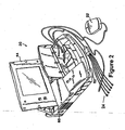
- FIG. 2 is a perspective view of programming unit 20 in accordance with the presently disclosed invention.
- programmer 20 includes a processing unit (not shown in the Figure) that in accordance with the presently disclosed invention is a personal computer type motherboard, e.g., a computer motherboard including an Intel Pentium 3 microprocessor and related circuitry such as digital memory.
- a personal computer type motherboard e.g., a computer motherboard including an Intel Pentium 3 microprocessor and related circuitry such as digital memory.
- programmer 20 comprises an outer housing 60, which is preferably made of thermal plastic or another suitably rugged yet relatively lightweight material.
- a carrying handle, designated generally as 62 in FIG. 2 is integrally formed into the front of housing 60. With handle 62, programmer 20 can be carried like a briefcase.
- Display screen 64 is disposed on the upper surface of housing 60.
- Display screen 64 folds down into a closed position (not shown) when programmer 20 is not in use, thereby reducing the size of programmer 20 and protecting the display surface of display 64 during transportation and storage thereof.
- a floppy disk drive is disposed within housing 60 and is accessible via a disk insertion slot (not shown).
- a hard disk drive is also disposed within housing 60, and it is contemplated that a hard disk drive activity indicator, (e.g., an LED, not shown) could be provided to give a visible indication of hard disk activation.
- programmer 20 is equipped with an internal printer (not shown) so that a hard copy of a patient's ECG or of graphics displayed on the programmer's display screen 64 can be generated.
- printers such as the AR-100 printer available from General Scanning Co., are known and commercially available.
- Articulating display screen 64 is preferably of the LCD or electro-luminescent type, characterized by being relatively thin as compared, for example, a cathode ray tube (CRT) or the like.
- display screen 64 is operatively coupled to the computer circuitry disposed within housing 60 and is adapted to provide a visual display of graphics and/or data under control of the internal computer.
- the Medtronic Model 9790 programmer is the implantable device-programming unit with which the present invention may be advantageously practiced.
- FIG. 3 is a block diagram of the electronic circuitry that makes up pulse generator 10 in accordance with the presently disclosed invention.
- pacemaker 10 comprises a primary stimulation control circuit 21 for controlling the device's pacing and sensing functions.
- the circuitry associated with stimulation control circuit 21 may be of conventional design, in accordance, for example, with what is disclosed Pat. No. 5,052,388 issued to Sivula et al. , Method And Apparatus For Implementing Activity Sensing In A Pulse Generator .
- certain components ofpulse generator 10 are conventional in their design and operation, such components will not be described herein in detail, as it is believed that design and implementation of such components would be a matter of routine to those of ordinary skill in the art.
- stimulation control circuit 21 in FIG. 3 includes sense amplifier circuitry 25, stimulating pulse output circuitry 26, a crystal clock 28, a random-access memory and read-only memory (RAM/ROM) unit 30, and a central processing unit (CPU) 32, all of which are well-known in the art.
- sense amplifier circuitry 25 stimulating pulse output circuitry 26
- crystal clock 28 a random-access memory and read-only memory (RAM/ROM) unit 30
- CPU central processing unit
- Pacemaker 10 also includes internal communication circuit 34 so that it is capable of communicating with external programmer/control unit 20, as described in Fig. 2 in greater detail.
- pulse generator 10 is coupled to one or more leads 14 which, when implanted, extend transvenously between the implant site of pulse generator 10 and the patient's heart 16, as previously noted with reference to FIG. 1 .
- leads 14 which, when implanted, extend transvenously between the implant site of pulse generator 10 and the patient's heart 16, as previously noted with reference to FIG. 1 .
- the connections between leads 14 and the various internal components of pulse generator 10 are facilitated by means of a conventional connector block assembly 11, shown in FIG. 1 .
- the coupling of the conductors of leads and internal electrical components of pulse generator 10 may be facilitated by means of a lead interface circuit 19 which functions, in a multiplexer-like manner, to selectively and dynamically establish necessary connections between various conductors in leads 14, including, for example, atrial tip and ring electrode conductors ATIP and ARING and ventricular tip and ring electrode conductors VTIP and VRING, and individual electrical components of pulse generator 10, as would be familiar to those of ordinary skill in the art.
- a lead interface circuit 19 which functions, in a multiplexer-like manner, to selectively and dynamically establish necessary connections between various conductors in leads 14, including, for example, atrial tip and ring electrode conductors ATIP and ARING and ventricular tip and ring electrode conductors VTIP and VRING, and individual electrical components of pulse generator 10, as would be familiar to those of ordinary skill in the art.
- the specific connections between leads 14 and the various components of pulse generator 10 are not shown in FIG.
- leads 14 will necessarily be coupled, either directly or indirectly, to sense amplifier circuitry 25 and stimulating pulse output circuit 26, in accordance with common practice, such that cardiac electrical signals may be conveyed to sensing circuitry 25, and such that stimulating pulses may be delivered to cardiac tissue, via leads 14.
- protection circuitry commonly included in implanted devices to protect, for example, the sensing circuitry of the device from high voltage stimulating pulses.
- stimulation control circuit 21 includes central processing unit 32 which may be an off-the-shelf programmable microprocessor or micro controller, but in the present invention is a custom integrated circuit. Although specific connections between CPU 32 and other components of stimulation control circuit 21 are not shown in FIG. 3 , it will be apparent to those of ordinary skill in the art that CPU 32 functions to control the timed operation of stimulating pulse output circuit 26 and sense amplifier circuit 25 under control of programming stored in RAM/ROM unit 30. It is believed that those of ordinary skill in the art will be familiar with such an operative arrangement.
- crystal oscillator circuit 28 in the presently preferred embodiment a 32,768-Hz crystal controlled oscillator provides main timing clock signals to stimulation control circuit 21.
- the lines over which such clocking signals are provided to the various timed components of pulse generator 10 are omitted from FIG. 3 for the sake of clarity.
- pulse generator 10 depicted in FIG. 3 are powered by means of a battery (not shown) that is contained within the hermetic enclosure of pacemaker 10, in accordance with common practice in the art.
- a battery not shown
- the battery and the connections between it and the other components of pulse generator 10 are not shown.
- Stimulating pulse output circuit 26 which functions to generate cardiac stimuli under control of signals issued by CPU 32, may be, for example, of the type disclosed in U.S. Pat. No. 4,476,868 to Thompson , entitled Body Stimulator Output Circuit .
- Sense amplifier circuit 25 which is of conventional design, functions to receive electrical cardiac signals from leads 14 and to process such signals to derive event signals reflecting the occurrence of specific cardiac electrical events, including atrial contractions (P-waves) and ventricular contractions (R-waves).
- CPU provides these event-indicating signals to CPU 32 for use in controlling the synchronous stimulating operations of pulse generator 10 in accordance with common practice in the art.
- these event-indicating signals may be communicated, via uplink transmission, to external programming unit 20 for visual display to a physician or clinician.
- pacemaker 10 may include numerous other components and subsystems, for example, activity sensors and associated circuitry. The presence or absence of such additional components in pacemaker 10, however, is not believed to be pertinent to the present invention, which relates primarily to the implementation and operation of communication subsystem 34 in pacemaker 10, and an associated communication subsystem in external unit 20.
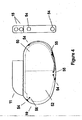
- FIG. 4 is a cross sectional view of implanted pacemaker 10 in which the present invention may be implemented.
- the major components of pacemaker 10 include a hermetic casing in which are housed electronic circuitry 52 and hermetic power source 50.
- Lead connector module 11 provides an enclosure in which the proximal ends of atrial and ventricular leads may be inserted into openings 15.
- Lead connector module 11 is connected to pacemaker casing 10 and as is well known in the art includes electrical connections (not shown) between lead connectors and hermetic feedthroughs (also not shown).
- feedthrough/electrode assemblies 54 are welded into place on a generally or substantially flattened periphery of the pacemaker casing.
- the complete periphery of the pacemaker may be manufactured with a slightly flattened perspective including rounded edges to accommodate the placement of feedthrough/electrode assemblies such as those disclosed in the present invention.
- These feedthrough/electrode assemblies 54 are welded to pacemaker casing for integral hermiticity and connected via wire 55 through separate feedthroughs 56 to gain access to electronic circuitry 52.
- FIGS. 5 represents several cross sectional views of alternative structures of the first embodiment of the present invention in combination with ECG sensing electrodes.
- the complete assembly is quite small and designed to match with the pacemaker casing. Because of the small size of the complete assembly, the sensing electrodes must be designed and manufactured from materials capable of detecting faint/very slight cardiac depolarization waveforms, such as the P-wave.
- the assembly of the subcutaneous electrodes including those disclosed in Figures 6 through 12 hereinbelow, must be hermetic (less than 10 -6 cc He/sec with 10 -9 cc He/sec preferred), biocompatible, and joinable to or fully integrable with the pacemaker casing.
- all the electrodes disclosed herein may be constructed from the following materials.
- the insulator may consist of glass, ceramic (direct braze), polymeric, or glass-ceramic.
- the ferrule may be fabricated from any suitable alloy or metal such as titanium, niobium, stainless steel, or combination of these metals and alloys.
- the feedthrough conductor may be made of any suitable alloy such as niobium, tantalum, platinum, or platinum-iridium.
- the sensing electrode may be constructed of any suitable material such as platinum, platinum black, titanium, titanium nitride, or ruthenium oxide, or combinations thereof.
- Electrode coating deposition methods including sintering (powder metallurgy), sputtering, plating, CVD, PVD, or other methods, can be used to obtain large surface areas and low polarization. Ion etching, directional solidification, or other processes may be used to texture the surface to increase the surface area of the electrode and to simplify manufacturability.
- FIGs. 5A and 5B illustrate simple subcutaneous ECG electrode assemblies.
- FIG. 5A shows feedthrough conductor 75, mounted in ferrule 73 with optional welding notch 70 to accommodate the welding of the pacemaker casing (not shown) to ferrule 73.
- Glass insulator 85 joins feedthrough conductor 75 and ferrule 73.
- feedthrough conductor 75 is machined to function as an ECG sensing electrode.
- Thin Film Electrodes for Sensing Cardiac Depolarization Signals by Guck et al, filed on December 13, 2000, US patent no. 2002/0072778 A1 , discloses a manufacturing process for conversion of feedthrough conductors to ECG electrodes.
- Fig. 5B displays brazed feedthrough 84 with a conductor 75 that is supported by insulator 76 and ferrule 73. These components are joined with gold braze 77.
- FIGs 5A and 5B disclose elegant electrode designs and a low profile. They have no appreciable protrusions and as such, lend themselves to an easier implant procedure and greater comfort for the patient.
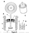
- FIG. 6 shows four views of the second embodiment of the present invention that utilizes an ECG sensing electrode with a large surface area.
- FIG. 6A is a cross sectional view, 6B a top view, 6C a perspective view, and 6D a cross sectional view all which represent, inter alia, a glass insulator within a modified ferrule casing.
- FIG. 6A a cross-sectional view of feedthrough conductor 75 terminating in a substantially flat-ended electrode 74 is shown. Electrode 74 is recessed within ferrule 73 that is welded to the pacemaker casing at optional welding notch 70. Thus, the complete assembly has no components that protrude above or outside of the pacemaker's casing.
- Feedthrough conductor 75 fits through opening in insulator 76 to which it is joined by braze 77. Insulator 76 maintains electrical isolation of the ECG signal as it circuits from sensing electrode 74 through feedthrough conductor 75 that is electrically connected to SEA circuitry within pacemaker 10.
- Braze 77 serves to hermetically seal the assembly and prevent the intrusion of body fluid that fills the cavity around electrode 74.
- the increased surface area of ECG sensing electrode 74 is one of the significant features of the invention.
- the geometric surface area is increased to improve detection of cardiac waveforms that have lesser amplitudes, for example, atrial fibrillation waves.
- increasing the geometric surface area may attenuate polarization effects at or around the ECG sensing electrode. Both features help to ensure the appropriate detection of ECG waveforms.
- the structure enables adequate detection, and transmission of cardiac depolarization signals.
- electrode coatings may be used to obtain larger surface areas and effect low polarization. Coating deposition methods may include sintering (powder metallurgy), sputtering, plating, CVD, PVD, or other methods.
- ion etching, directional solidification, or other processes may be used to texture the surface to increase the surface area of the electrode and to simplify manufacturability.
- Sensing electrode 74 may be integral and homogenous with feedthrough conductor 75 and established via deposition methods such as sintering, sputtering, plating, etc. Alternatively, sensing electrode 74 may be subsequently attached to the feedthrough conductor via shape memory alloys, welding, brazing, compression interference joints, etc.
- FIG. 6D shows a cross sectional view of the embodiment in which the same feedthrough conductor 75 and sensing electrode74 are used, with the exception that glass 85 is used to 1) join the feedthrough conductor/electrode with the ferrule, 2) electrically insulate so as to maintain signal integrity, and 3) hermetically seal the assembly.
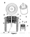
- FIG. 7 shows four views of a third embodiment of the present invention that utilizes an ECG sensing electrode with a low profile and a filter(i.e/, capacitor).
- FIG. 7A shows the addition of a multi-layer ceramic capacitor 71 that serves to filter electromagnetic interference to improve the detected signal prior to passing the signal on to the pacemaker circuitry.
- the feedthrough conductor and feedthrough ferrule are electrically joined to the capacitor.
- Capacitor 71 can be placed in the assembly and stabilized using non-conductive epoxy 79.
- Conductive epoxy 78 may be used to couple capacitor 71 with feedthrough conductor 75.
- the filter capacitor 71 is used with glass insulator 85.
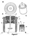
- FIG. 8 shows four views of yet another embodiment of the present invention that utilizes both an ECG sensing electrode with a high surface area and a capacitor.
- ECG sensing electrode 74 is implemented in a manner similar to that disclosed in conjunction with FIG. 6 , the second embodiment.
- the reasons for using a sensing electrode with a high surface area are the same as those cited in FIG. 6 .
- FIG. 9 shows three views of how the third and fourth embodiments ( FIGs. 7 and 8 ) of the present invention may be assembled with a polyimide disk to render the assembly leak testable.
- This figure focuses on the important element of testing for hermeticity, that is, determining whether the assembly may be tested for leaks.
- the addition of polyimide disk 72 immediately below capacitor 71 accomplishes this purpose.
- Leak Testable Capacitive Filtered Feedthrough for an Implantable Medical Device by Fraley et al, filed October 25, US 6,349,025 .
- the same element could be added to an assembly using glass as an insulator (not shown).
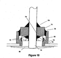
- FIG. 10 shows a cross sectional view of the present invention with a low-profile/high surface area disk electrode 80.
- electrode 80 may be implemented in the embodiments disclosed in FIGs 6 and 8 to further increase the surface area of the ECG sensing electrode.
- the electrodes are attached to the feedthrough conductor after welding the feedthrough to the shield. Electrode attachment may be performed by laser weld, resistance spot weld, mechanical interference, or other equivalent methods.
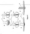
- FIG. 11 is a representation of various electrode types that may be used with the assemblies shown in the embodiments disclosed hereinabove.
- FIG. 11A is a standard, substantially flat headed, feedthrough conductor to which is attached sensing electrode 86 (as was shown in FIG. 6 ).
- Alternative types of electrodes may be used, as shown in FIGS. 11B and 11C .
- Feedthrough conductor 75 may be modified to contain a platinum powder chamber 67.
- Electrode 74 in FIG. 11B is coated and sintered with Pt powder 68.
- Electrode 74 in FIG. 11C is coated and sintered with Pt powder 68 and with Pt black 69. In accordance with the present invention, any combination of sintered Pt 68 and Pt black 69 may be used.
- Electrodes may include a steroid plug 82 as shown in FIG 11D.
- FIGs 11E and 11F represent stages of manufacture in accordance with the present invention. Specifically, as shown in Fig. 11F , electrode 75 protrudes through electrode disk 80. The protrusion is preferably laser welded or mechanically formed to have a compliant contour as shown in FIG 11E . The feedthrough conductor fits through the low-profile electrode disk 80. As shown in FIG. 11F by dotted lines, the feedthrough conductor protrudes through the disk and is welded to attach electrode 74 to feedthrough conductor as shown in FIG. 11E .
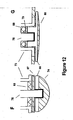
- FIGS. 12F and 12G are examples of assemblies that make use of shape memory alloy 66 to allow easier and less costly fabrication.
- FIG. 12F represents the implementation of a ceramic or glass insulator 83, with an insulator of another material 87 to electrically isolate sensing electrode 74 from ferrule 73 and pacemaker casing (not shown).
- the electrode in FIG. 12G is an alternate embodiment using epoxy backfill 79 and insulator 88 to electrically isolate the low-profile sensing electrode 80 from ferrule 73 and pacemaker casing.
Abstract
Claims (29)
- Dispositif médical implantable (IMD) (10) incluant au moins une électrode incorporée dans un trou d'interconnexion (75) en vue d'un couplage électrique à un circuit (52) du dispositif IMD afin de détecter des signaux physiologiques, l'électrode en combinaison avec le trou d'interconnexion comportant :l'électrode (74) disposée dans une ferrule (73) s'adaptant à une périphérie du dispositif IMD ; ladite ferrule ayant une première extrémité et une seconde extrémité ;des moyens isolants (76, 85) positionnés entre ladite électrode de détection (74) et ladite ferrule (73) ; etdes moyens de couplage électrique positionnés entre ladite électrode (74) et ledit circuit (52) et, en outre, dans lequel ledit dispositif IMD a un boîtier et caractérisé en ce que ledit boîtier a une paroi extérieure de boîtier ayant une périphérie en grande partie aplanie et dans lequel ladite première extrémité de ferrule est montée au même niveau que ladite paroi de boîtier extérieure et la seconde extrémité de ferrule s'étend dans ledit boîtier.
- Dispositif médical implantable selon la revendication 1, dans lequel ladite électrode inclut une extrémité en grande partie plate intégrée à une périphérie exposée généralement aplanie du dispositif IMD formant un joint hermétique avec celle-ci.
- Dispositif médical implantable selon la revendication 2, dans lequel une pluralité d'électrodes sont réparties autour de ladite périphérie exposée du dispositif médical implantable formant un réseau.
- Dispositif médical implantable selon la revendication 2, dans lequel une brasure (77) connecte ladite électrode, ladite ferrule (73) et ledit isolant pour former ledit joint hermétique.
- Dispositif médical implantable (IMD) comportant un système d'électrodes de détection, dans lequel une ou plusieurs électrodes sont disposées autour de la périphérie périmétrique dudit dispositif médical implantable (IMD), l'électrode comportant :une première extrémité intégrée à un conducteur de trou d'interconnexion ;des moyens isolants (76) ayant une ouverture pour recouvrir un segment de ladite première extrémité ;des moyens de brasure (77) pour fermer hermétiquement et connecter intégralement ladite première extrémité audit isolant et ledit isolant à ladite ferrule ; etune seconde extrémité formant une grande zone de surface s'étendant à travers ladite ferrule (73) ; ladite grande zone de surface de ladite seconde extrémité étant en conformité planaire avec la périphérie du dispositif IMD ;ladite première extrémité étant électriquement couplée à un circuit (52) dans le dispositif médical implantable, ladite seconde extrémité offrant une détection pour traiter des signaux physiologiques obtenus via ladite grande zone de surface et, en outre, dans lequel ledit dispositif médical implantable a un boîtier et caractérisé en ce que ledit boîtier a une paroi extérieure de boîtier ayant une périphérie en grande partie aplanie et dans lequel ladite première extrémité de ferrule est montée au même niveau que ladite paroi de boîtier extérieure et la seconde extrémité de ferrule s'étend dans ledit boîtier.
- Dispositif médical implantable comportant le système de la revendication 5, dans lequel une pluralité d'électrodes sont réparties au niveau de la périphérie périmétrique du dispositif médical implantable.
- Dispositif médical implantable comportant le système de la revendication 5 dans lequel lesdits moyens isolants (76) et lesdits moyens de brasure (77) sont remplacés conjointement par une structure en verre (85).
- Dispositif médical implantable comportant le système de la revendication 5, dans lequel ladite seconde extrémité est adaptée pour s'étendre dans des fluides corporels du patient dans lequel le dispositif médical implantable (10) est implanté.
- Dispositif médical implantable (IMD) selon la revendication 1 ou la revendication 5, ledit boîtier étant fermé hermétiquement et ladite paroi extérieure du boîtier étant adaptée pour être exposée au corps et une paroi intérieure du boîtier entourant un circuit de détection (52) dans ledit boîtier pour traiter des signaux électriques du corps détectés entre au moins deux desdites électrodes (74) supportées par le boîtier, dans lequel
au moins une électrode (74) comportant ledit trou d'interconnexion électrique (75) montée pour s'étendre entre ladite paroi extérieure du boîtier et ladite paroi intérieur du boîtier, ledit trou d'interconnexion (75) comportant ladite ferrule ayant une surface de ferrule intérieure s'étendant entre une première extrémité de ferrule et une seconde extrémité de ferrule, une broche à trou d'interconnexion électriquement conductrice (75) s'étendant entre une première extrémité de broche à trou d'interconnexion et une seconde extrémité de broche à trou d'interconnexion, et un isolant électrique s'étendant entre ladite broche à trou d'interconnexion et ladite paroi intérieure de la ferrule et supportant ladite broche à trou d'interconnexion, et comportant en outre :des moyens pour monter ladite première extrémité de paroi de la ferrule pour étendre ladite broche à trou d'interconnexion (75) à travers ledit boîtier pour exposer ladite première extrémité de la broche à trou d'interconnexion au corps et pour enfermer hermétiquement ladite seconde extrémité de broche à trou d'interconnexion (75) dans ledit boîtier ; etdes moyens pour coupler électriquement ladite seconde extrémité de broche à trou d'interconnexion (75) audit circuit de détection (52) de manière à permettre à ladite première extrémité de broche à trou d'interconnexion (75) de fonctionner en tant que première électrode de détection opérationnelle en conjonction avec une seconde électrode de détection couplée au circuit de détection pour permettre une détection de signaux électriques du corps. - Dispositif médical implantable selon la revendication 9 lorsqu'elle dépend de la revendication 1, dans lequel :ledit isolant (76) est monté pour s'étendre entre ladite paroi intérieure de la ferrule dans ledit boîtier et ladite broche à trou d'interconnexion (75) et supporte la première extrémité de la broche à trou d'interconnexion (75) encastrée dans la ferrule et éloignée de la première extrémité de la ferrule.
- Dispositif médical implantable selon la revendication 10, dans lequel :la ferrule à trou d'interconnexion est de forme cylindrique entre la première extrémité de la ferrule et la seconde extrémité de la ferrule et a un diamètre de ferrule ; etla broche à trou d'interconnexion (75) a un diamètre d'électrode agrandie inférieur au diamètre de la ferrule au niveau de la première extrémité de la broche à trou d'interconnexion formant une zone de surface d'électrode agrandie.
- Dispositif médical implantable selon la revendication 9 lorsqu'elle dépend de la revendication 5, dans lequel :ledit isolant (76) est monté pour s'étendre entre ladite paroi intérieure de la ferrule dans ledit boîtier et ladite broche à trou d'interconnexion et supporte la première extrémité de la broche la broche à trou d'interconnexion s'étendant après la première extrémité de la ferrule et à l'extérieur de la paroi exposée du boîtier.
- Dispositif médical implantable selon la revendication 12, dans lequel :la broche à trou d'interconnexion (75) a un diamètre s'étendant à travers ledit isolant ; etla broche à trou d'interconnexion (75) a une électrode agrandie ayant un diamètre d'électrode agrandie au niveau de la première extrémité de la broche à trou d'interconnexion fournissant une zone de surface d'électrode agrandie s'étendant vers l'extérieur sur la paroi extérieure du boîtier.
- Dispositif médical implantable selon la revendication 13, comportant en outre des moyens de délogement pour séparer l'électrode agrandie s'étendant vers l'extérieur sur la paroi extérieure du boîtier de la première extrémité de la ferrule (73) et de la paroi extérieure du boîtier.
- Dispositif médical implantable selon la revendication 13, dans lequel :la ferrule à trou d'interconnexion a une forme cylindrique entre la première extrémité de la ferrule (73) et la seconde extrémité de la ferrule et a un diamètre de ferrule ;la broche à trou d'interconnexion (75) a une électrode agrandie ayant un diamètre d'électrode excédant le diamètre de la ferrule au niveau de la première extrémité de la broche à trou d'interconnexion formant une zone de surface d'électrode agrandie s'étendant vers l'extérieur sur la paroi extérieure du boîtier.
- Dispositif médical implantable selon la revendication 15, comportant en outre des moyens isolants pour isoler électriquement l'électrode agrandie s'étendant vers l'extérieur sur la paroi extérieure du boîtier de la première extrémité de la ferrule et de la paroi extérieure du boîtier.
- Dispositif médical implantable selon la revendication 11 ou la revendication 15, dans lequel la zone de surface d'électrode agrandie a été améliorée par un traitement de surface sélectionné à partir du groupe constitué d'un frittage, d'une pulvérisation, d'un dépôt de métal, d'un dépôt chimique en phase vapeur et d'un dépôt physique en phase gazeuse.
- Dispositif médical implantable selon la revendication 11 ou la revendication 15, dans lequel le trou d'interconnexion comporte en outre un filtre capacitif discoïdal (71) monté entre ladite paroi intérieure de la ferrule (73) et ladite broche à trou d'interconnexion (75).
- Dispositif médical implantable selon la revendication 9, dans lequel une pluralité d'électrodes de détection (74) sont toutes formées d'une pluralité similaire ou même desdits trous d'interconnexion chacun étant électriquement connecté audit circuit de détection (52) pour traiter une pluralité de signaux électriques détectés à partir de paires sélectionnées de premières extrémités de broches à trou d'interconnexion (75).
- Dispositif médical implantable selon la revendication 19, dans lequel :ledit boîtier comporte une paire de parois de boîtier principal opposées reliées au niveau de leurs périphéries par un périmètre, et chaque ferrule (73) de ladite pluralité de trous d'interconnexion est fixée à une ouverture à travers ledit périmètre dudit boîtier.
- Dispositif médical implantable selon la revendication 9 ou la revendication 10, dans lequel :la broche à trou d'interconnexion (75) a un diamètre de broche s'étendant à travers ledit isolant ; etla broche à trou d'interconnexion (75) a un diamètre d'électrode agrandie au niveau de la première extrémité de la broche à trou d'interconnexion offrant une zone de surface d'électrode agrandie.
- Dispositif médical implantable selon la revendication 9, dans lequel ledit boîtier comporte une paire de parois de boîtier principal opposées reliées au niveau de leurs périphéries par un périmètre, et la ferrule (73) dudit trou d'interconnexion est fixée à une ouverture à travers ledit périmètre dudit boîtier.
- Dispositif médical implantable selon l'une quelconque des revendications 9, 10, 13, dans lequel la première extrémité de la broche à trou d'interconnexion (75) a été soumise à un traitement de surface sélectionné à partir du groupe constitué d'un frittage, d'une pulvérisation, d'un dépôt de métal, d'un dépôt chimique en phase vapeur et d'un dépôt physique en phase gazeuse.
- Dispositif médical implantable selon l'une quelconque des revendications 9, 10, 13, dans lequel chaque trou d'interconnexion (75) comporte en outre un filtre capacitif (71) monté entre ladite ferrule et ladite broche à trou d'interconnexion (75).
- Dispositif médical implantable selon la revendication 9, dans lequel l'isolant comporte en outre un verre électriquement isolant (85) s'étendant entre une partie de la longueur de la broche à trou d'interconnexion (75) et au moins une partie de la surface de la ferrule intérieure (73) et collé à celle-ci pour former un joint hermétique de la broche à la ferrule (73).
- Dispositif médical implantable selon la revendication 9, dans lequel l'isolant comporte en outre un isolant en céramique électriquement isolant s'étendant entre une partie de la longueur de la broche à trou d'interconnexion et collé à celle-ci par une brasure (77) et au moins une partie de la surface de ferrule intérieure et collé à celle-ci par une brasure pour former un joint hermétique de la broche à la ferrule.
- Dispositif médical implantable selon la revendication 9, dans lequel l'isolant s'étend entre une première partie de la longueur de la broche à trou d'interconnexion et une première partie de la surface de la ferrule intérieure, et le trou d'interconnexion comporte en outre :un filtre capacitif (71) monté entre une seconde partie de la surface de la ferrule intérieure et la broche à trou d'interconnexion ; etun disque polyamide (72) positionné entre le filtre capacitif (71) et l'isolant pour faciliter un essai d'étanchéité hermétique de l'isolant.
- Dispositif médical implantable selon la revendication 9, dans lequel une structure d'alliage à mémoire de forme (66) est implémentée entre le trou d'interconnexion (75) et l'électrode de détection (74).
- Dispositif médical implantable selon la revendication 9, dans lequel ledit trou d'interconnexion (75) et ladite électrode (74) ont été intégralement fixés en utilisant l'un d'un processus de soudage et d'un processus de formage mécanique.
Applications Claiming Priority (3)
| Application Number | Priority Date | Filing Date | Title |
|---|---|---|---|
| US850331 | 1992-03-10 | ||
| US09/850,331 US6622046B2 (en) | 2001-05-07 | 2001-05-07 | Subcutaneous sensing feedthrough/electrode assembly |
| PCT/US2002/008889 WO2002089904A2 (fr) | 2001-05-07 | 2002-03-20 | Ensemble electrode/ traversee pour la detection sous-cutanee |
Publications (2)
| Publication Number | Publication Date |
|---|---|
| EP1406692A2 EP1406692A2 (fr) | 2004-04-14 |
| EP1406692B1 true EP1406692B1 (fr) | 2010-04-21 |
Family
ID=25307844
Family Applications (1)
| Application Number | Title | Priority Date | Filing Date |
|---|---|---|---|
| EP02725315A Expired - Lifetime EP1406692B1 (fr) | 2001-05-07 | 2002-03-20 | Ensemble électrode/traversée pour la détection sous-cutanée |
Country Status (6)
| Country | Link |
|---|---|
| US (1) | US6622046B2 (fr) |
| EP (1) | EP1406692B1 (fr) |
| JP (1) | JP2004537347A (fr) |
| CA (1) | CA2446456A1 (fr) |
| DE (1) | DE60236086D1 (fr) |
| WO (1) | WO2002089904A2 (fr) |
Families Citing this family (238)
| Publication number | Priority date | Publication date | Assignee | Title |
|---|---|---|---|---|
| US7283874B2 (en) | 2000-10-16 | 2007-10-16 | Remon Medical Technologies Ltd. | Acoustically powered implantable stimulating device |
| KR100751310B1 (ko) * | 2001-09-24 | 2007-08-22 | 삼성에스디아이 주식회사 | 캡 조립체 및, 그것을 구비한 각형 2 차 전지 |
| US7120992B2 (en) * | 2002-06-28 | 2006-10-17 | Advanced Bionics Corporation | Method of making an electronic module |
| US7189204B2 (en) | 2002-12-04 | 2007-03-13 | Cardiac Pacemakers, Inc. | Sleep detection using an adjustable threshold |
| US7596408B2 (en) | 2002-12-09 | 2009-09-29 | Medtronic, Inc. | Implantable medical device with anti-infection agent |
| AU2003297723A1 (en) | 2002-12-09 | 2004-06-30 | Medtronic, Inc. | Reducing relative intermodule motion in a modular implantable medical device |
| US7016145B2 (en) * | 2003-02-19 | 2006-03-21 | Seagate Technology Llc | Hermetically sealed data storage device |
| US7392081B2 (en) * | 2003-02-28 | 2008-06-24 | Cardiac Pacemakers, Inc. | Subcutaneous cardiac stimulator employing post-shock transthoracic asystole prevention pacing |
| US7493175B2 (en) * | 2003-04-11 | 2009-02-17 | Cardiac Pacemakers, Inc. | Subcutaneous lead with tined fixation |
| US7979122B2 (en) | 2003-04-11 | 2011-07-12 | Cardiac Pacemakers, Inc. | Implantable sudden cardiac death prevention device with reduced programmable feature set |
| US7865233B2 (en) | 2003-04-11 | 2011-01-04 | Cardiac Pacemakers, Inc. | Subcutaneous cardiac signal discrimination employing non-electrophysiologic signal |
| US7349742B2 (en) * | 2003-04-11 | 2008-03-25 | Cardiac Pacemakers, Inc. | Expandable fixation elements for subcutaneous electrodes |
| US7499758B2 (en) | 2003-04-11 | 2009-03-03 | Cardiac Pacemakers, Inc. | Helical fixation elements for subcutaneous electrodes |
| US7529592B2 (en) * | 2003-04-11 | 2009-05-05 | Cardiac Pacemakers, Inc. | Subcutaneous electrode and lead with temporary pharmacological agents |
| US20040220628A1 (en) * | 2003-04-11 | 2004-11-04 | Wagner Darrell Orvin | Subcutaneous defibrillation timing correlated with induced skeletal muscle contraction |
| US7389138B2 (en) | 2003-04-11 | 2008-06-17 | Cardiac Pacemakers, Inc. | Electrode placement determination for subcutaneous cardiac monitoring and therapy |
| US7566318B2 (en) | 2003-04-11 | 2009-07-28 | Cardiac Pacemakers, Inc. | Ultrasonic subcutaneous dissection tool incorporating fluid delivery |
| US20040230272A1 (en) * | 2003-04-11 | 2004-11-18 | Cates Adam W. | Subcutaneous lead with temporary pharmacological agents |
| US7117035B2 (en) | 2003-04-11 | 2006-10-03 | Cardiac Pacemakers, Inc. | Subcutaneous cardiac stimulation system with patient activity sensing |
| US7302294B2 (en) | 2003-04-11 | 2007-11-27 | Cardiac Pacemakers, Inc. | Subcutaneous cardiac sensing and stimulation system employing blood sensor |
| US7555335B2 (en) | 2003-04-11 | 2009-06-30 | Cardiac Pacemakers, Inc. | Biopotential signal source separation using source impedances |
| US7218966B2 (en) | 2003-04-11 | 2007-05-15 | Cardiac Pacemakers, Inc. | Multi-parameter arrhythmia discrimination |
| US7702399B2 (en) | 2003-04-11 | 2010-04-20 | Cardiac Pacemakers, Inc. | Subcutaneous electrode and lead with phoresis based pharmacological agent delivery |
| US20040230229A1 (en) * | 2003-04-11 | 2004-11-18 | Lovett Eric G. | Hybrid transthoracic/intrathoracic cardiac stimulation devices and methods |
| US7236819B2 (en) | 2003-04-11 | 2007-06-26 | Cardiac Pacemakers, Inc. | Separation of a subcutaneous cardiac signal from a plurality of composite signals |
| US8116868B2 (en) | 2003-04-11 | 2012-02-14 | Cardiac Pacemakers, Inc. | Implantable device with cardiac event audio playback |
| US7047071B2 (en) | 2003-04-11 | 2006-05-16 | Cardiac Pacemakers, Inc. | Patient stratification for implantable subcutaneous cardiac monitoring and therapy |
| US20040220626A1 (en) * | 2003-04-11 | 2004-11-04 | Wagner Darrell Orvin | Distributed subcutaneous defibrillation system |
| US20040204734A1 (en) * | 2003-04-11 | 2004-10-14 | Wagner Darrell Orvin | Tunneling tool with subcutaneous transdermal illumination |
| US7263401B2 (en) | 2003-05-16 | 2007-08-28 | Medtronic, Inc. | Implantable medical device with a nonhermetic battery |
| US20050003268A1 (en) * | 2003-05-16 | 2005-01-06 | Scott Erik R. | Battery housing configuration |
| US7239146B2 (en) | 2003-07-11 | 2007-07-03 | Cardiac Pacemakers, Inc. | Indicator of remaining energy in storage cell of implantable medical device |
| US7887493B2 (en) | 2003-09-18 | 2011-02-15 | Cardiac Pacemakers, Inc. | Implantable device employing movement sensing for detecting sleep-related disorders |
| US8002553B2 (en) | 2003-08-18 | 2011-08-23 | Cardiac Pacemakers, Inc. | Sleep quality data collection and evaluation |
| US7396333B2 (en) | 2003-08-18 | 2008-07-08 | Cardiac Pacemakers, Inc. | Prediction of disordered breathing |
| ATE413902T1 (de) | 2003-08-18 | 2008-11-15 | Cardiac Pacemakers Inc | Patientenüberwachungssystem |
| US8606356B2 (en) | 2003-09-18 | 2013-12-10 | Cardiac Pacemakers, Inc. | Autonomic arousal detection system and method |
| US7194308B2 (en) | 2003-11-12 | 2007-03-20 | Cardiac Pacemakers, Inc. | System and method for monitoring or reporting battery status of implantable medical device |
| US20060247693A1 (en) | 2005-04-28 | 2006-11-02 | Yanting Dong | Non-captured intrinsic discrimination in cardiac pacing response classification |
| US7774064B2 (en) | 2003-12-12 | 2010-08-10 | Cardiac Pacemakers, Inc. | Cardiac response classification using retriggerable classification windows |
| US8521284B2 (en) | 2003-12-12 | 2013-08-27 | Cardiac Pacemakers, Inc. | Cardiac response classification using multisite sensing and pacing |
| US7765005B2 (en) * | 2004-02-12 | 2010-07-27 | Greatbatch Ltd. | Apparatus and process for reducing the susceptability of active implantable medical devices to medical procedures such as magnetic resonance imaging |
| US7756581B2 (en) * | 2004-02-18 | 2010-07-13 | Medtronic, Inc. | Implantable temperature sensor |
| US7339353B1 (en) | 2004-03-10 | 2008-03-04 | Quallion Llc | Power system for managing power from multiple power sources |
| US7596399B2 (en) | 2004-04-29 | 2009-09-29 | Medtronic, Inc | Implantation of implantable medical device |
| US20050245984A1 (en) | 2004-04-30 | 2005-11-03 | Medtronic, Inc. | Implantable medical device with lubricious material |
| EP1747043A4 (fr) | 2004-05-04 | 2008-04-23 | Univ Rochester | Matrice d'interface bio-electro-physiologique implantable |
| WO2005107864A1 (fr) * | 2004-05-04 | 2005-11-17 | University Of Rochester | Defibrillateur a synchronisation automatique sans fil implantable |
| WO2005107852A1 (fr) * | 2004-05-04 | 2005-11-17 | University Of Rochester | Dispositif electrophysiologique intravasculaire implantable sans fil pour la detection et la stimulation neurologique/cardiovasculaire |
| US7706866B2 (en) | 2004-06-24 | 2010-04-27 | Cardiac Pacemakers, Inc. | Automatic orientation determination for ECG measurements using multiple electrodes |
| US9192772B1 (en) | 2004-06-29 | 2015-11-24 | Quallion Llc | Portable medical power system |
| US7509170B2 (en) | 2005-05-09 | 2009-03-24 | Cardiac Pacemakers, Inc. | Automatic capture verification using electrocardiograms sensed from multiple implanted electrodes |
| US7797036B2 (en) | 2004-11-30 | 2010-09-14 | Cardiac Pacemakers, Inc. | Cardiac activation sequence monitoring for ischemia detection |
| US7457664B2 (en) | 2005-05-09 | 2008-11-25 | Cardiac Pacemakers, Inc. | Closed loop cardiac resynchronization therapy using cardiac activation sequence information |
| US7917196B2 (en) | 2005-05-09 | 2011-03-29 | Cardiac Pacemakers, Inc. | Arrhythmia discrimination using electrocardiograms sensed from multiple implanted electrodes |
| US7890159B2 (en) | 2004-09-30 | 2011-02-15 | Cardiac Pacemakers, Inc. | Cardiac activation sequence monitoring and tracking |
| US7805185B2 (en) | 2005-05-09 | 2010-09-28 | Cardiac Pacemakers, In. | Posture monitoring using cardiac activation sequences |
| US8329314B1 (en) | 2004-10-12 | 2012-12-11 | Boston Scientific Neuromodulation Corporation | Hermetically bonding ceramic and titanium with a palladium braze |
| US7771838B1 (en) | 2004-10-12 | 2010-08-10 | Boston Scientific Neuromodulation Corporation | Hermetically bonding ceramic and titanium with a Ti-Pd braze interface |
| US7996072B2 (en) | 2004-12-21 | 2011-08-09 | Cardiac Pacemakers, Inc. | Positionally adaptable implantable cardiac device |
| US8577455B2 (en) * | 2005-01-18 | 2013-11-05 | Medtronic, Inc. | Method and apparatus for arrhythmia detection in a medical device |
| US7145076B2 (en) * | 2005-02-08 | 2006-12-05 | Greatbatch, Inc. | Method for minimizing stress in feedthrough capacitor filter assemblies |
| US7680534B2 (en) | 2005-02-28 | 2010-03-16 | Cardiac Pacemakers, Inc. | Implantable cardiac device with dyspnea measurement |
| US7702385B2 (en) * | 2005-11-16 | 2010-04-20 | Boston Scientific Neuromodulation Corporation | Electrode contact configurations for an implantable stimulator |
| US20060217777A1 (en) * | 2005-03-22 | 2006-09-28 | James Strom | Apparatus and methods of monitoring cardiac activity utilizing implantable shroud-based electrodes |
| US7392086B2 (en) | 2005-04-26 | 2008-06-24 | Cardiac Pacemakers, Inc. | Implantable cardiac device and method for reduced phrenic nerve stimulation |
| US7493166B2 (en) * | 2005-04-28 | 2009-02-17 | Medtronic, Inc. | Electrical contact for a feedthrough/electrode assembly |
| US8391990B2 (en) | 2005-05-18 | 2013-03-05 | Cardiac Pacemakers, Inc. | Modular antitachyarrhythmia therapy system |
| US20070049975A1 (en) * | 2005-09-01 | 2007-03-01 | Cates Adam W | Active can with dedicated defibrillation and sensing electrodes |
| US20070118180A1 (en) | 2005-11-18 | 2007-05-24 | Quan Ni | Cardiac resynchronization therapy for improved hemodynamics based on disordered breathing detection |
| US7761158B2 (en) * | 2005-12-20 | 2010-07-20 | Cardiac Pacemakers, Inc. | Detection of heart failure decompensation based on cumulative changes in sensor signals |
| US8078278B2 (en) | 2006-01-10 | 2011-12-13 | Remon Medical Technologies Ltd. | Body attachable unit in wireless communication with implantable devices |
| US20070179538A1 (en) * | 2006-01-30 | 2007-08-02 | Deno D C | Implantable subcutaneous medical device providing post-extra-systolic potentiation therapy |
| US8478399B2 (en) * | 2006-01-31 | 2013-07-02 | Paul J. Degroot | Method and apparatus for controlling arrhythmia detection and treatment based on patient posture |
| US7769452B2 (en) * | 2006-03-29 | 2010-08-03 | Medtronic, Inc. | Method and apparatus for detecting arrhythmias in a medical device |
| US7991471B2 (en) * | 2006-03-29 | 2011-08-02 | Medtronic, Inc. | Method and apparatus for detecting arrhythmias in a subcutaneous medical device |
| US7894894B2 (en) | 2006-03-29 | 2011-02-22 | Medtronic, Inc. | Method and apparatus for detecting arrhythmias in a subcutaneous medical device |
| US7941214B2 (en) * | 2006-03-29 | 2011-05-10 | Medtronic, Inc. | Method and apparatus for detecting arrhythmias in a subcutaneous medical device |
| US7496409B2 (en) * | 2006-03-29 | 2009-02-24 | Medtronic, Inc. | Implantable medical device system and method with signal quality monitoring and response |
| US8326425B2 (en) * | 2006-03-30 | 2012-12-04 | Cardiac Pacemakers, Inc. | Feedthrough connector for implantable device |
| US7803014B2 (en) * | 2006-03-30 | 2010-09-28 | Cardiac Pacemakers, Inc. | Implantable medical device assembly and manufacturing method |
| US20070233217A1 (en) * | 2006-03-31 | 2007-10-04 | Zhongping Yang | Implantable medical electrode |
| US8095205B2 (en) | 2006-03-31 | 2012-01-10 | Medtronic, Inc. | Method and apparatus for verifying a determined cardiac event in a medical device based on detected variation in hemodynamic status |
| US7668597B2 (en) * | 2006-03-31 | 2010-02-23 | Medtronic, Inc. | Feedthrough array for use in implantable medical devices |
| US7647095B2 (en) * | 2006-03-31 | 2010-01-12 | Medtronic, Inc. | Method and apparatus for verifying a determined cardiac event in a medical device based on detected variation in hemodynamic status |
| US9084901B2 (en) | 2006-04-28 | 2015-07-21 | Medtronic, Inc. | Cranial implant |
| US7498516B1 (en) | 2006-06-14 | 2009-03-03 | Boston Scientific Neuromodulation Corporation | Feedthru assembly |
| US8527048B2 (en) | 2006-06-29 | 2013-09-03 | Cardiac Pacemakers, Inc. | Local and non-local sensing for cardiac pacing |
| US7801623B2 (en) * | 2006-06-29 | 2010-09-21 | Medtronic, Inc. | Implantable medical device having a conformal coating |
| US7580741B2 (en) | 2006-08-18 | 2009-08-25 | Cardiac Pacemakers, Inc. | Method and device for determination of arrhythmia rate zone thresholds using a probability function |
| US8712507B2 (en) | 2006-09-14 | 2014-04-29 | Cardiac Pacemakers, Inc. | Systems and methods for arranging and labeling cardiac episodes |
| US8209013B2 (en) | 2006-09-14 | 2012-06-26 | Cardiac Pacemakers, Inc. | Therapeutic electrical stimulation that avoids undesirable activation |
| US8437837B2 (en) * | 2006-09-29 | 2013-05-07 | Medtronic, Inc. | Method and apparatus for induced T-wave alternans assessment |
| US7941208B2 (en) | 2006-11-29 | 2011-05-10 | Cardiac Pacemakers, Inc. | Therapy delivery for identified tachyarrhythmia episode types |
| JP5231525B2 (ja) | 2007-03-26 | 2013-07-10 | レモン メディカル テクノロジーズ, リミテッド | 埋込型医療デバイスのためのバイアスされた音響スイッチ |
| US7904153B2 (en) * | 2007-04-27 | 2011-03-08 | Medtronic, Inc. | Method and apparatus for subcutaneous ECG vector acceptability and selection |
| US8068901B2 (en) * | 2007-05-01 | 2011-11-29 | Medtronic, Inc. | Method and apparatus for adjusting a sensing parameter |
| US8095206B2 (en) * | 2007-05-01 | 2012-01-10 | Medtronic, Inc. | Method and apparatus for detecting arrhythmias in a medical device |
| US7774049B2 (en) * | 2007-05-01 | 2010-08-10 | Medtronic, Inc. | Method and apparatus for determining oversensing in a medical device |
| US7937135B2 (en) * | 2007-05-01 | 2011-05-03 | Medtronic, Inc. | Method and apparatus for adjusting a sensing parameter |
| US7715906B2 (en) * | 2007-06-04 | 2010-05-11 | Medtronic, Inc. | Method and apparatus for detecting noise in an implantable medical device |
| US8265736B2 (en) | 2007-08-07 | 2012-09-11 | Cardiac Pacemakers, Inc. | Method and apparatus to perform electrode combination selection |
| US9037239B2 (en) | 2007-08-07 | 2015-05-19 | Cardiac Pacemakers, Inc. | Method and apparatus to perform electrode combination selection |
| EP2254661B1 (fr) | 2008-02-14 | 2015-10-07 | Cardiac Pacemakers, Inc. | Appareil pour la détection de stimulation phrénique |
| US9545215B2 (en) * | 2008-07-31 | 2017-01-17 | Medtronic, Inc. | Apparatus and method for detecting cardiac events |
| US8321014B2 (en) | 2008-10-06 | 2012-11-27 | Cardiac Pacemakers, Inc. | Dynamic cardiac resynchronization therapy by tracking intrinsic conduction |
| EP2361115A1 (fr) | 2008-10-27 | 2011-08-31 | Cardiac Pacemakers, Inc. | Procédés et systèmes pour recharger des dispositifs implantables |
| US9393432B2 (en) | 2008-10-31 | 2016-07-19 | Medtronic, Inc. | Non-hermetic direct current interconnect |
| US8352008B2 (en) * | 2009-06-10 | 2013-01-08 | Medtronic, Inc. | Active noise cancellation in an optical sensor signal |
| WO2010144648A1 (fr) * | 2009-06-10 | 2010-12-16 | Medtronic, Inc. | Réduction de choc utilisant la saturation en oxygène dans un tissu à étalonnage absolu et fraction du volume d'hémoglobine total |
| US8634890B2 (en) * | 2009-06-10 | 2014-01-21 | Medtronic, Inc. | Device and method for monitoring of absolute oxygen saturation and tissue hemoglobin concentration |
| US8346332B2 (en) * | 2009-06-10 | 2013-01-01 | Medtronic, Inc. | Absolute calibrated tissue oxygen saturation and total hemoglobin volume fraction |
| US8515537B2 (en) * | 2009-06-10 | 2013-08-20 | Medtronic, Inc. | Tissue oxygenation monitoring in heart failure |
| WO2012102971A1 (fr) | 2011-01-26 | 2012-08-02 | Medtronic, Inc. | Dispositifs médicaux implantables et ensembles boîtiers de connecteurs associés utilisant des conducteurs couplés électriquement à des broches de traversée |
| US10449373B2 (en) | 2009-07-31 | 2019-10-22 | Medtronic, Inc. | Connector enclosure assemblies of medical devices including an angled lead passageway |
| US9242108B2 (en) * | 2009-07-31 | 2016-01-26 | Medtronic, Inc. | Medical device surface electrode |
| US20110066017A1 (en) * | 2009-09-11 | 2011-03-17 | Medtronic, Inc. | Method and apparatus for post-shock evaluation using tissue oxygenation measurements |
| US9129749B2 (en) | 2009-12-18 | 2015-09-08 | Cardiac Pacemakers, Inc. | Sintered electrodes to store energy in an implantable medical device |
| US9123470B2 (en) | 2009-12-18 | 2015-09-01 | Cardiac Pacemakers, Inc. | Implantable energy storage device including a connection post to connect multiple electrodes |
| US8873220B2 (en) | 2009-12-18 | 2014-10-28 | Cardiac Pacemakers, Inc. | Systems and methods to connect sintered aluminum electrodes of an energy storage device |
| US9269498B2 (en) * | 2009-12-18 | 2016-02-23 | Cardiac Pacemakers, Inc. | Sintered capacitor electrode including multiple thicknesses |
| US9144689B2 (en) | 2010-12-28 | 2015-09-29 | Medtronic, Inc. | Medical devices including metallic connector enclosures |
| US9560980B2 (en) | 2012-01-31 | 2017-02-07 | Medtronic, Inc. | Automatic selection of electrode vectors for assessing risk of heart failure decompensation events |
| US9431814B2 (en) | 2012-02-15 | 2016-08-30 | Cardiac Pacemakers, Inc. | Ferrule for implantable medical device |
| US9351648B2 (en) | 2012-08-24 | 2016-05-31 | Medtronic, Inc. | Implantable medical device electrode assembly |
| US8532785B1 (en) | 2012-09-26 | 2013-09-10 | Medtronic, Inc. | Therapy delivery method and system for implantable medical devices |
| US9168379B2 (en) | 2012-09-26 | 2015-10-27 | Medtronic, Inc. | Therapy delivery method and system for implantable medical devices |
| US8886314B2 (en) | 2012-09-26 | 2014-11-11 | Medtronic, Inc. | Therapy delivery method and system for implantable medical devices |
| CN104661702B (zh) | 2012-09-26 | 2016-12-21 | 美敦力公司 | 可植入医疗设备的治疗递送方法和系统 |
| US8744572B1 (en) | 2013-01-31 | 2014-06-03 | Medronic, Inc. | Systems and methods for leadless pacing and shock therapy |
| US8972005B2 (en) | 2013-03-12 | 2015-03-03 | Medtronic, Inc. | Subthreshold lead impedance measurement for subcutaneous device |
| EP3038669B1 (fr) * | 2013-08-28 | 2018-01-03 | Heartware, Inc. | Dispositif de passage |
| US9220911B2 (en) | 2013-09-11 | 2015-12-29 | Medtronic, Inc. | Implantable medical devices with power supply noise isolation |
| US9511233B2 (en) | 2013-11-21 | 2016-12-06 | Medtronic, Inc. | Systems and methods for leadless cardiac resynchronization therapy |
| US20150196769A1 (en) | 2014-01-10 | 2015-07-16 | Cardiac Pacemakers, Inc. | Methods and systems for improved communication between medical devices |
| US10449361B2 (en) | 2014-01-10 | 2019-10-22 | Cardiac Pacemakers, Inc. | Systems and methods for treating cardiac arrhythmias |
| JP6781044B2 (ja) | 2014-01-10 | 2020-11-04 | カーディアック ペースメイカーズ, インコーポレイテッド | 心臓不整脈を検出するシステム |
| US9138821B2 (en) * | 2014-01-17 | 2015-09-22 | Medtronic, Inc. | Methods for simultaneously brazing a ferrule and lead pins |
| US9492671B2 (en) | 2014-05-06 | 2016-11-15 | Medtronic, Inc. | Acoustically triggered therapy delivery |
| US9669224B2 (en) | 2014-05-06 | 2017-06-06 | Medtronic, Inc. | Triggered pacing system |
| US10463866B2 (en) | 2014-07-11 | 2019-11-05 | Cardiac Pacemakers, Inc. | Systems and methods for treating cardiac arrhythmias |
| CN107073275B (zh) | 2014-08-28 | 2020-09-01 | 心脏起搏器股份公司 | 具有触发的消隐周期的医疗设备 |
| WO2016126968A1 (fr) | 2015-02-06 | 2016-08-11 | Cardiac Pacemakers, Inc. | Systèmes et procédés pour l'administration sécurisée d'une thérapie par stimulation électrique |
| WO2016126613A1 (fr) | 2015-02-06 | 2016-08-11 | Cardiac Pacemakers, Inc. | Systèmes et méthodes de traitement d'arythmies cardiaques |
| WO2016130477A2 (fr) | 2015-02-09 | 2016-08-18 | Cardiac Pacemakers, Inc. | Dispositif médical implantable comportant une étiquette d'identification radio-opaque |
| US11285326B2 (en) | 2015-03-04 | 2022-03-29 | Cardiac Pacemakers, Inc. | Systems and methods for treating cardiac arrhythmias |
| US10213610B2 (en) | 2015-03-18 | 2019-02-26 | Cardiac Pacemakers, Inc. | Communications in a medical device system with link quality assessment |
| US10050700B2 (en) | 2015-03-18 | 2018-08-14 | Cardiac Pacemakers, Inc. | Communications in a medical device system with temporal optimization |
| US10004906B2 (en) | 2015-07-16 | 2018-06-26 | Medtronic, Inc. | Confirming sensed atrial events for pacing during resynchronization therapy in a cardiac medical device and medical device system |
| EP3337559B1 (fr) | 2015-08-20 | 2019-10-16 | Cardiac Pacemakers, Inc. | Systèmes et procédés de communication entre des dispositifs médicaux |
| WO2017031221A1 (fr) | 2015-08-20 | 2017-02-23 | Cardiac Pacemakers, Inc. | Systèmes et procédés de communication entre des dispositifs médicaux |
| US9968787B2 (en) | 2015-08-27 | 2018-05-15 | Cardiac Pacemakers, Inc. | Spatial configuration of a motion sensor in an implantable medical device |
| US9956414B2 (en) | 2015-08-27 | 2018-05-01 | Cardiac Pacemakers, Inc. | Temporal configuration of a motion sensor in an implantable medical device |
| WO2017040153A1 (fr) | 2015-08-28 | 2017-03-09 | Cardiac Pacemakers, Inc. | Systèmes et procédés pour l'administration de thérapie et la détection de signal sensible au comportement |
| US10159842B2 (en) | 2015-08-28 | 2018-12-25 | Cardiac Pacemakers, Inc. | System and method for detecting tamponade |
| US10226631B2 (en) | 2015-08-28 | 2019-03-12 | Cardiac Pacemakers, Inc. | Systems and methods for infarct detection |
| WO2017044389A1 (fr) | 2015-09-11 | 2017-03-16 | Cardiac Pacemakers, Inc. | Détection et confirmation d'arythmie |
| EP3359251B1 (fr) | 2015-10-08 | 2019-08-07 | Cardiac Pacemakers, Inc. | Ajustement des fréquences de stimulation dans un dispositif médical implantable |
| DE102015121818A1 (de) | 2015-12-15 | 2017-06-22 | Biotronik Se & Co. Kg | Durchführung eines medizinelektronischen Geräts, Verfahren zur Herstellung einer solchen und medizinelektronisches Gerät |
| EP3389775B1 (fr) | 2015-12-17 | 2019-09-25 | Cardiac Pacemakers, Inc. | Communication menée dans un système de dispositif médical |
| US10905886B2 (en) | 2015-12-28 | 2021-02-02 | Cardiac Pacemakers, Inc. | Implantable medical device for deployment across the atrioventricular septum |
| US10583303B2 (en) | 2016-01-19 | 2020-03-10 | Cardiac Pacemakers, Inc. | Devices and methods for wirelessly recharging a rechargeable battery of an implantable medical device |
| WO2017136548A1 (fr) | 2016-02-04 | 2017-08-10 | Cardiac Pacemakers, Inc. | Système de pose avec capteur de force pour dispositif cardiaque sans fil |
| US9731138B1 (en) | 2016-02-17 | 2017-08-15 | Medtronic, Inc. | System and method for cardiac pacing |
| CN108883286B (zh) | 2016-03-31 | 2021-12-07 | 心脏起搏器股份公司 | 具有可充电电池的可植入医疗设备 |
| US9802055B2 (en) | 2016-04-04 | 2017-10-31 | Medtronic, Inc. | Ultrasound powered pulse delivery device |
| US10668294B2 (en) | 2016-05-10 | 2020-06-02 | Cardiac Pacemakers, Inc. | Leadless cardiac pacemaker configured for over the wire delivery |
| US10328272B2 (en) | 2016-05-10 | 2019-06-25 | Cardiac Pacemakers, Inc. | Retrievability for implantable medical devices |
| JP6764956B2 (ja) | 2016-06-27 | 2020-10-07 | カーディアック ペースメイカーズ, インコーポレイテッド | 再同期ペーシング管理に皮下で感知されたp波を使用する心臓治療法システム |
| US11207527B2 (en) | 2016-07-06 | 2021-12-28 | Cardiac Pacemakers, Inc. | Method and system for determining an atrial contraction timing fiducial in a leadless cardiac pacemaker system |
| US10426962B2 (en) | 2016-07-07 | 2019-10-01 | Cardiac Pacemakers, Inc. | Leadless pacemaker using pressure measurements for pacing capture verification |
| CN109475743B (zh) | 2016-07-20 | 2022-09-02 | 心脏起搏器股份公司 | 在无引线心脏起搏器系统中利用心房收缩定时基准的系统 |
| US10952686B2 (en) | 2016-08-02 | 2021-03-23 | Medtronic, Inc. | Mobile application to prompt physical action to measure physiologic response in implantable device |
| US10391319B2 (en) | 2016-08-19 | 2019-08-27 | Cardiac Pacemakers, Inc. | Trans septal implantable medical device |
| EP3503970B1 (fr) | 2016-08-24 | 2023-01-04 | Cardiac Pacemakers, Inc. | Resynchronisation cardiaque utilisant l'encouragement de la fusion pour la gestion de la synchronisation |
| WO2018039335A1 (fr) | 2016-08-24 | 2018-03-01 | Cardiac Pacemakers, Inc. | Thérapie intégrée de resynchronisation cardiaque à dispositifs multiples utilisant l'onde p pour stimuler la synchronisation. |
| US10994145B2 (en) | 2016-09-21 | 2021-05-04 | Cardiac Pacemakers, Inc. | Implantable cardiac monitor |
| CN109803720B (zh) | 2016-09-21 | 2023-08-15 | 心脏起搏器股份公司 | 具有容纳其内部部件并充当电池壳和内部电池的端子的壳体的无引线刺激设备 |
| US10758737B2 (en) | 2016-09-21 | 2020-09-01 | Cardiac Pacemakers, Inc. | Using sensor data from an intracardially implanted medical device to influence operation of an extracardially implantable cardioverter |
| EP3532159B1 (fr) | 2016-10-27 | 2021-12-22 | Cardiac Pacemakers, Inc. | Système de pose de dispositif médical implantable avec capteur intégré |
| US10434314B2 (en) | 2016-10-27 | 2019-10-08 | Cardiac Pacemakers, Inc. | Use of a separate device in managing the pace pulse energy of a cardiac pacemaker |
| US10413733B2 (en) | 2016-10-27 | 2019-09-17 | Cardiac Pacemakers, Inc. | Implantable medical device with gyroscope |
| WO2018081275A1 (fr) | 2016-10-27 | 2018-05-03 | Cardiac Pacemakers, Inc. | Thérapie de resynchronisation cardiaque à dispositifs multiples avec des améliorations de synchronisation |
| US10561330B2 (en) | 2016-10-27 | 2020-02-18 | Cardiac Pacemakers, Inc. | Implantable medical device having a sense channel with performance adjustment |
| US10765871B2 (en) | 2016-10-27 | 2020-09-08 | Cardiac Pacemakers, Inc. | Implantable medical device with pressure sensor |
| US10617874B2 (en) | 2016-10-31 | 2020-04-14 | Cardiac Pacemakers, Inc. | Systems and methods for activity level pacing |
| JP6843235B2 (ja) | 2016-10-31 | 2021-03-17 | カーディアック ペースメイカーズ, インコーポレイテッド | 活動レベル・ペーシングのためのシステムおよび方法 |
| US10583301B2 (en) | 2016-11-08 | 2020-03-10 | Cardiac Pacemakers, Inc. | Implantable medical device for atrial deployment |
| WO2018089308A1 (fr) | 2016-11-09 | 2018-05-17 | Cardiac Pacemakers, Inc. | Systèmes, dispositifs et procédés pour régler des paramètres d'impulsion de stimulation cardiaque pour un dispositif de stimulation cardiaque |
| EP3541471B1 (fr) | 2016-11-21 | 2021-01-20 | Cardiac Pacemakers, Inc. | Stimulateur cardiaque sans sonde fournissant un traitement de resynchronisation cardiaque |
| US10639486B2 (en) | 2016-11-21 | 2020-05-05 | Cardiac Pacemakers, Inc. | Implantable medical device with recharge coil |
| EP3541473B1 (fr) | 2016-11-21 | 2020-11-11 | Cardiac Pacemakers, Inc. | Stimulateur cardiaque sans sonde à communication multimodale |
| CN109996585B (zh) | 2016-11-21 | 2023-06-13 | 心脏起搏器股份公司 | 具有导磁壳体和围绕该壳体设置的感应线圈的植入式医疗设备 |
| US10881869B2 (en) | 2016-11-21 | 2021-01-05 | Cardiac Pacemakers, Inc. | Wireless re-charge of an implantable medical device |
| US11207532B2 (en) | 2017-01-04 | 2021-12-28 | Cardiac Pacemakers, Inc. | Dynamic sensing updates using postural input in a multiple device cardiac rhythm management system |
| EP3573708B1 (fr) | 2017-01-26 | 2021-03-10 | Cardiac Pacemakers, Inc. | Dispositif implantable sans fil à fixation amovible |
| US10029107B1 (en) | 2017-01-26 | 2018-07-24 | Cardiac Pacemakers, Inc. | Leadless device with overmolded components |
| JP7000438B2 (ja) | 2017-01-26 | 2022-01-19 | カーディアック ペースメイカーズ, インコーポレイテッド | 冗長メッセージ送信を伴う人体デバイス通信 |
| US10433737B2 (en) | 2017-01-27 | 2019-10-08 | Medtronic, Inc. | Medical device including feedthrough assembly |
| US10905872B2 (en) | 2017-04-03 | 2021-02-02 | Cardiac Pacemakers, Inc. | Implantable medical device with a movable electrode biased toward an extended position |
| CN110740779B (zh) | 2017-04-03 | 2024-03-08 | 心脏起搏器股份公司 | 具有基于感测到的心率的起搏脉冲能量调节的心脏起搏器 |
| US10881862B2 (en) | 2017-05-10 | 2021-01-05 | Medtronic, Inc. | Estimating RV-timings from left ventricular (LV) sensing times for adaptive cardiac resynchronization therapy using DDD/VDD LV pacing without a right ventricular (RV) lead |
| EP3668592B1 (fr) | 2017-08-18 | 2021-11-17 | Cardiac Pacemakers, Inc. | Dispositif médical implantable avec capteur de pression |
| WO2019036568A1 (fr) | 2017-08-18 | 2019-02-21 | Cardiac Pacemakers, Inc. | Dispositif médical implantable comprenant un concentrateur de flux et une bobine de réception disposée autour du concentrateur de flux |
| WO2019060302A1 (fr) | 2017-09-20 | 2019-03-28 | Cardiac Pacemakers, Inc. | Dispositif médical implantable avec modes de fonctionnement multiples |
| US10694967B2 (en) | 2017-10-18 | 2020-06-30 | Medtronic, Inc. | State-based atrial event detection |
| US11185703B2 (en) | 2017-11-07 | 2021-11-30 | Cardiac Pacemakers, Inc. | Leadless cardiac pacemaker for bundle of his pacing |
| US11260216B2 (en) | 2017-12-01 | 2022-03-01 | Cardiac Pacemakers, Inc. | Methods and systems for detecting atrial contraction timing fiducials during ventricular filling from a ventricularly implanted leadless cardiac pacemaker |
| US11071870B2 (en) | 2017-12-01 | 2021-07-27 | Cardiac Pacemakers, Inc. | Methods and systems for detecting atrial contraction timing fiducials and determining a cardiac interval from a ventricularly implanted leadless cardiac pacemaker |
| EP3717059A1 (fr) | 2017-12-01 | 2020-10-07 | Cardiac Pacemakers, Inc. | Procédés et systèmes pour détecter des repères de synchronisation de contraction auriculaire dans une fenêtre de recherche à partir d'un stimulateur cardiaque sans fil implanté de manière ventriculaire |
| EP3717060B1 (fr) | 2017-12-01 | 2022-10-05 | Cardiac Pacemakers, Inc. | Stimulateur cardiaque sans fil à comportement réversible |
| US11529523B2 (en) | 2018-01-04 | 2022-12-20 | Cardiac Pacemakers, Inc. | Handheld bridge device for providing a communication bridge between an implanted medical device and a smartphone |
| EP3735293B1 (fr) | 2018-01-04 | 2022-03-09 | Cardiac Pacemakers, Inc. | Stimulation double chambre sans communication battement à battement |
| US10561847B2 (en) | 2018-02-27 | 2020-02-18 | Medtronic, Inc. | Capture management in leadless cardiac pacing device |
| JP2021519117A (ja) | 2018-03-23 | 2021-08-10 | メドトロニック,インコーポレイテッド | 頻拍のためのVfA心臓治療 |
| US11400296B2 (en) | 2018-03-23 | 2022-08-02 | Medtronic, Inc. | AV synchronous VfA cardiac therapy |
| JP2021518192A (ja) | 2018-03-23 | 2021-08-02 | メドトロニック,インコーポレイテッド | VfA心臓再同期治療 |
| US10596383B2 (en) | 2018-04-03 | 2020-03-24 | Medtronic, Inc. | Feature based sensing for leadless pacing therapy |
| US11253708B2 (en) | 2018-05-24 | 2022-02-22 | Medtronic, Inc. | Machined features of enclosures for implantable medical devices |
| CN112770807A (zh) | 2018-09-26 | 2021-05-07 | 美敦力公司 | 心房至心室心脏疗法中的捕获 |
| EP3870267A1 (fr) | 2018-10-25 | 2021-09-01 | Pacesetter, Inc. | Traversée de biostimulateur ayant une électrode cupule intégrée |
| WO2020092652A1 (fr) * | 2018-10-30 | 2020-05-07 | Newrom Biomedical, Llc | Dispositifs de neurostimulation et de capteur comprenant des électrodes à faible impédance, et procédés, systèmes et utilisations associés |
| US11951313B2 (en) | 2018-11-17 | 2024-04-09 | Medtronic, Inc. | VFA delivery systems and methods |
| GB2580918A (en) * | 2019-01-29 | 2020-08-05 | Saietta Group Ltd | Axial flux electrical machine |
| US11679265B2 (en) | 2019-02-14 | 2023-06-20 | Medtronic, Inc. | Lead-in-lead systems and methods for cardiac therapy |
| US11697025B2 (en) | 2019-03-29 | 2023-07-11 | Medtronic, Inc. | Cardiac conduction system capture |
| US11213676B2 (en) | 2019-04-01 | 2022-01-04 | Medtronic, Inc. | Delivery systems for VfA cardiac therapy |
| US11712188B2 (en) | 2019-05-07 | 2023-08-01 | Medtronic, Inc. | Posterior left bundle branch engagement |
| CN110244546A (zh) * | 2019-05-29 | 2019-09-17 | 华为技术有限公司 | 用于智能手表的一体结构和智能手表 |
| US11305127B2 (en) | 2019-08-26 | 2022-04-19 | Medtronic Inc. | VfA delivery and implant region detection |
| US11717186B2 (en) | 2019-08-27 | 2023-08-08 | Medtronic, Inc. | Body stability measurement |
| US11147978B2 (en) * | 2019-10-30 | 2021-10-19 | Wyss Center For Bio And Neuro Engineering | Feedthrough protective cover |
| US11918820B2 (en) | 2020-01-21 | 2024-03-05 | Pacesetter, Inc. | Leadless biostimulator having overmolded header assembly |
| US11813466B2 (en) | 2020-01-27 | 2023-11-14 | Medtronic, Inc. | Atrioventricular nodal stimulation |
| EP4110456A1 (fr) * | 2020-02-25 | 2023-01-04 | BIOTRONIK SE & Co. KG | Traversée électrique à électrode intégrée et dispositif médical |
| US11911168B2 (en) | 2020-04-03 | 2024-02-27 | Medtronic, Inc. | Cardiac conduction system therapy benefit determination |
| US11602313B2 (en) | 2020-07-28 | 2023-03-14 | Medtronic, Inc. | Determining a fall risk responsive to detecting body position movements |
| US11813464B2 (en) | 2020-07-31 | 2023-11-14 | Medtronic, Inc. | Cardiac conduction system evaluation |
Citations (8)
| Publication number | Priority date | Publication date | Assignee | Title |
|---|---|---|---|---|
| US3981309A (en) * | 1974-12-23 | 1976-09-21 | American Optical Corporation | Patient stimulating pacer electrode |
| US4310000A (en) * | 1980-01-23 | 1982-01-12 | Medtronic, Inc. | Implantable pulse generator having separate passive sensing reference electrode |
| US4612100A (en) * | 1983-12-20 | 1986-09-16 | Siemens Aktiengesellschaft | Method for the fabrication of an implantable electrode |
| DE4112936A1 (de) * | 1990-04-17 | 1991-10-24 | Biotronik Mess & Therapieg | Elektrode fuer medizinische anwendungen |
| US5333095A (en) * | 1993-05-03 | 1994-07-26 | Maxwell Laboratories, Inc., Sierra Capacitor Filter Division | Feedthrough filter capacitor assembly for human implant |
| US5331966A (en) * | 1991-04-05 | 1994-07-26 | Medtronic, Inc. | Subcutaneous multi-electrode sensing system, method and pacer |
| US5836992A (en) * | 1994-10-04 | 1998-11-17 | Medtronic, Inc. | Filtered feedthrough assembly for implantable medical device |
| WO2002034332A1 (fr) * | 2000-10-25 | 2002-05-02 | Medtronic, Inc. | Electrodes de ceramique multicouches permettant de detecter les signaux de depolarisation cardiaque |
Family Cites Families (29)
| Publication number | Priority date | Publication date | Assignee | Title |
|---|---|---|---|---|
| DE2429953B2 (de) | 1974-06-21 | 1980-03-27 | Siemens Ag, 1000 Berlin Und 8000 Muenchen | Schaltungsanordnung zur Verarbeitung physiologischer Meßsignale |
| US3983867A (en) | 1975-09-29 | 1976-10-05 | Robert Case | Method and apparatus for providing hexaxial ecg display |
| US4082086A (en) | 1976-12-13 | 1978-04-04 | M I Systems, Inc. | Ecg monitoring pad |
| US4170227A (en) | 1976-12-27 | 1979-10-09 | Electronics For Medicine, Inc. | Apparatus and method for ECG baseline shift detecting |
| US4121576A (en) | 1977-02-09 | 1978-10-24 | Fred Samuel Greensite | Method and apparatus for processing vectorcardiographic signals for enabling quantitative determination of the percentage of heart muscle tissue affected by an intervention |
| US4476868A (en) | 1978-11-06 | 1984-10-16 | Medtronic, Inc. | Body stimulator output circuit |
| US4375817A (en) | 1979-07-19 | 1983-03-08 | Medtronic, Inc. | Implantable cardioverter |
| US4263919A (en) | 1979-10-12 | 1981-04-28 | Levin Kenneth M | Heartbeat detection and artifact discrimination method and apparatus |
| US4313443A (en) | 1980-09-11 | 1982-02-02 | Nasa | Pocket ECG electrode |
| PL133646B1 (en) | 1981-10-22 | 1985-06-29 | Os Bad Rozwojowy Tech Medyc | Non-invasive method of measuring activation of hearth stimuli conducting system between successive stimulations |
| US4729376A (en) | 1985-05-28 | 1988-03-08 | Cordis Corporation | Cardiac pacer and method providing means for periodically determining capture threshold and adjusting pulse output level accordingly |
| US4674508A (en) | 1985-05-28 | 1987-06-23 | Cordis Corporation | Low-power consumption cardiac pacer based on automatic verification of evoked contractions |
| US4964877A (en) | 1986-01-14 | 1990-10-23 | Wilson Greatbatch Ltd. | Non-aqueous lithium battery |
| US5052388A (en) | 1989-12-22 | 1991-10-01 | Medtronic, Inc. | Method and apparatus for implementing activity sensing in a pulse generator |
| US5235979B1 (en) | 1991-03-15 | 1994-11-01 | Angeion Corp | Dual battery system for implantable defibrillator |
| US5250373A (en) | 1991-09-10 | 1993-10-05 | Wilson Greatbatch Ltd. | Internal electrode and assembly method for electrochemical cells |
| US5345362A (en) | 1993-04-29 | 1994-09-06 | Medtronic, Inc. | Portable computer apparatus with articulating display panel |
| US5439760A (en) | 1993-11-19 | 1995-08-08 | Medtronic, Inc. | High reliability electrochemical cell and electrode assembly therefor |
| US5434017A (en) | 1993-11-19 | 1995-07-18 | Medtronic, Inc. | Isolated connection for an electrochemical cell |
| US5431695A (en) * | 1993-11-23 | 1995-07-11 | Medtronic, Inc. | Pacemaker |
| US5549717A (en) | 1994-03-03 | 1996-08-27 | Wilson Greatbatch Ltd. | Method of making prismatic cell |
| US5782891A (en) * | 1994-06-16 | 1998-07-21 | Medtronic, Inc. | Implantable ceramic enclosure for pacing, neurological, and other medical applications in the human body |
| US5650759A (en) * | 1995-11-09 | 1997-07-22 | Hittman Materials & Medical Components, Inc. | Filtered feedthrough assembly having a mounted chip capacitor for medical implantable devices and method of manufacture therefor |
| US5614331A (en) | 1995-12-22 | 1997-03-25 | Wilson Greatbatch Ltd. | Medium and high discharge rate combination battery and method |
| DE59711597D1 (de) | 1997-04-16 | 2004-06-09 | Litronik Batterietechnologie G | Implantierbares medizinisches Mehrfunktionsgerät |
| WO1999005750A1 (fr) | 1997-07-25 | 1999-02-04 | Cardiac Pacemakers, Inc. | Systeme de batteries pour dispositif medical implantable |
| US6008625A (en) | 1998-01-16 | 1999-12-28 | Wilson Greatbatch Ltd. | Use of double cells to power an implantable medical device |
| US6052623A (en) * | 1998-11-30 | 2000-04-18 | Medtronic, Inc. | Feedthrough assembly for implantable medical devices and methods for providing same |
| US6498951B1 (en) * | 2000-10-13 | 2002-12-24 | Medtronic, Inc. | Implantable medical device employing integral housing for a formable flat battery |
-
2001
- 2001-05-07 US US09/850,331 patent/US6622046B2/en not_active Expired - Fee Related
-
2002
- 2002-03-20 EP EP02725315A patent/EP1406692B1/fr not_active Expired - Lifetime
- 2002-03-20 JP JP2002587034A patent/JP2004537347A/ja active Pending
- 2002-03-20 WO PCT/US2002/008889 patent/WO2002089904A2/fr active Application Filing
- 2002-03-20 DE DE60236086T patent/DE60236086D1/de not_active Expired - Lifetime
- 2002-03-20 CA CA002446456A patent/CA2446456A1/fr not_active Abandoned
Patent Citations (8)
| Publication number | Priority date | Publication date | Assignee | Title |
|---|---|---|---|---|
| US3981309A (en) * | 1974-12-23 | 1976-09-21 | American Optical Corporation | Patient stimulating pacer electrode |
| US4310000A (en) * | 1980-01-23 | 1982-01-12 | Medtronic, Inc. | Implantable pulse generator having separate passive sensing reference electrode |
| US4612100A (en) * | 1983-12-20 | 1986-09-16 | Siemens Aktiengesellschaft | Method for the fabrication of an implantable electrode |
| DE4112936A1 (de) * | 1990-04-17 | 1991-10-24 | Biotronik Mess & Therapieg | Elektrode fuer medizinische anwendungen |
| US5331966A (en) * | 1991-04-05 | 1994-07-26 | Medtronic, Inc. | Subcutaneous multi-electrode sensing system, method and pacer |
| US5333095A (en) * | 1993-05-03 | 1994-07-26 | Maxwell Laboratories, Inc., Sierra Capacitor Filter Division | Feedthrough filter capacitor assembly for human implant |
| US5836992A (en) * | 1994-10-04 | 1998-11-17 | Medtronic, Inc. | Filtered feedthrough assembly for implantable medical device |
| WO2002034332A1 (fr) * | 2000-10-25 | 2002-05-02 | Medtronic, Inc. | Electrodes de ceramique multicouches permettant de detecter les signaux de depolarisation cardiaque |
Also Published As
| Publication number | Publication date |
|---|---|
| US20020165588A1 (en) | 2002-11-07 |
| EP1406692A2 (fr) | 2004-04-14 |
| WO2002089904A3 (fr) | 2003-04-17 |
| DE60236086D1 (de) | 2010-06-02 |
| CA2446456A1 (fr) | 2002-11-14 |
| JP2004537347A (ja) | 2004-12-16 |
| US6622046B2 (en) | 2003-09-16 |
| WO2002089904A9 (fr) | 2004-05-21 |
| WO2002089904A2 (fr) | 2002-11-14 |
Similar Documents
| Publication | Publication Date | Title |
|---|---|---|
| EP1406692B1 (fr) | Ensemble électrode/traversée pour la détection sous-cutanée | |
| US6564106B2 (en) | Thin film electrodes for sensing cardiac depolarization signals | |
| EP1406695A2 (fr) | Dispositif medical implantable a source d'energie en cellule double | |
| EP1330290B1 (fr) | Electrodes de ceramique multicouches permettant de detecter les signaux de depolarisation cardiaque | |
| US6512940B1 (en) | Subcutaneous spiral electrode for sensing electrical signals of the heart | |
| EP1331970B1 (fr) | Connecteur de recouvrement circulaire et boitiers d'electrode destines a un reseau d'electrodes sous cutanees et a des ecg sans derivation | |
| JP2004537347A5 (fr) | ||
| US6728576B2 (en) | Non-contact EKG | |
| EP1345653B1 (fr) | Surveillance de stimulateur cardiaque entierement automatique et sans connecteur | |
| US20080004535A1 (en) | Implantable medical device with sensing electrodes | |
| US20060217777A1 (en) | Apparatus and methods of monitoring cardiac activity utilizing implantable shroud-based electrodes | |
| US20060217778A1 (en) | Methods of fabrication of shroud-based electrodes for monitoring cardiac activity | |
| EP1901807B1 (fr) | Contact electrique pour ensemble traversee/electrode | |
| WO2008116067A2 (fr) | Procédés et appareil pour avertir des patients d'événements physiologiques et d'une fonction de dispositif |
Legal Events
| Date | Code | Title | Description |
|---|---|---|---|
| PUAI | Public reference made under article 153(3) epc to a published international application that has entered the european phase |
Free format text: ORIGINAL CODE: 0009012 |
|
| 17P | Request for examination filed |
Effective date: 20031204 |
|
| AK | Designated contracting states |
Kind code of ref document: A2 Designated state(s): AT BE CH CY DE DK ES FI FR GB GR IE IT LI LU MC NL PT SE TR |
|
| RAP1 | Party data changed (applicant data changed or rights of an application transferred) |
Owner name: MEDTRONIC, INC. |
|
| GRAP | Despatch of communication of intention to grant a patent |
Free format text: ORIGINAL CODE: EPIDOSNIGR1 |
|
| RTI1 | Title (correction) |
Free format text: SUBCUTANEOUS SENSING FEEDTHROUGH/ELECTRODE ASSEMBLY |
|
| GRAS | Grant fee paid |
Free format text: ORIGINAL CODE: EPIDOSNIGR3 |
|
| GRAA | (expected) grant |
Free format text: ORIGINAL CODE: 0009210 |
|
| AK | Designated contracting states |
Kind code of ref document: B1 Designated state(s): CH DE FR LI NL SE |
|
| REG | Reference to a national code |
Ref country code: CH Ref legal event code: EP |
|
| REF | Corresponds to: |
Ref document number: 60236086 Country of ref document: DE Date of ref document: 20100602 Kind code of ref document: P |
|
| REG | Reference to a national code |
Ref country code: NL Ref legal event code: VDEP Effective date: 20100421 |
|
| PG25 | Lapsed in a contracting state [announced via postgrant information from national office to epo] |
Ref country code: SE Free format text: LAPSE BECAUSE OF FAILURE TO SUBMIT A TRANSLATION OF THE DESCRIPTION OR TO PAY THE FEE WITHIN THE PRESCRIBED TIME-LIMIT Effective date: 20100421 Ref country code: NL Free format text: LAPSE BECAUSE OF FAILURE TO SUBMIT A TRANSLATION OF THE DESCRIPTION OR TO PAY THE FEE WITHIN THE PRESCRIBED TIME-LIMIT Effective date: 20100421 |
|
| PLBE | No opposition filed within time limit |
Free format text: ORIGINAL CODE: 0009261 |
|
| STAA | Information on the status of an ep patent application or granted ep patent |
Free format text: STATUS: NO OPPOSITION FILED WITHIN TIME LIMIT |
|
| 26N | No opposition filed |
Effective date: 20110124 |
|
| REG | Reference to a national code |
Ref country code: FR Ref legal event code: RM |
|
| REG | Reference to a national code |
Ref country code: CH Ref legal event code: PL |
|
| PG25 | Lapsed in a contracting state [announced via postgrant information from national office to epo] |
Ref country code: LI Free format text: LAPSE BECAUSE OF NON-PAYMENT OF DUE FEES Effective date: 20110331 Ref country code: CH Free format text: LAPSE BECAUSE OF NON-PAYMENT OF DUE FEES Effective date: 20110331 |
|
| PGFP | Annual fee paid to national office [announced via postgrant information from national office to epo] |
Ref country code: FR Payment date: 20140317 Year of fee payment: 13 |
|
| PGFP | Annual fee paid to national office [announced via postgrant information from national office to epo] |
Ref country code: DE Payment date: 20140327 Year of fee payment: 13 |
|
| REG | Reference to a national code |
Ref country code: DE Ref legal event code: R082 Ref document number: 60236086 Country of ref document: DE Representative=s name: DEHNS, GB |
|
| REG | Reference to a national code |
Ref country code: DE Ref legal event code: R119 Ref document number: 60236086 Country of ref document: DE |
|
| REG | Reference to a national code |
Ref country code: FR Ref legal event code: ST Effective date: 20151130 |
|
| PG25 | Lapsed in a contracting state [announced via postgrant information from national office to epo] |
Ref country code: DE Free format text: LAPSE BECAUSE OF NON-PAYMENT OF DUE FEES Effective date: 20151001 |
|
| PG25 | Lapsed in a contracting state [announced via postgrant information from national office to epo] |
Ref country code: FR Free format text: LAPSE BECAUSE OF NON-PAYMENT OF DUE FEES Effective date: 20150331 |