EP1406319A1 - Dispositif de commande de valves - Google Patents
Dispositif de commande de valves Download PDFInfo
- Publication number
- EP1406319A1 EP1406319A1 EP03292446A EP03292446A EP1406319A1 EP 1406319 A1 EP1406319 A1 EP 1406319A1 EP 03292446 A EP03292446 A EP 03292446A EP 03292446 A EP03292446 A EP 03292446A EP 1406319 A1 EP1406319 A1 EP 1406319A1
- Authority
- EP
- European Patent Office
- Prior art keywords
- pushers
- blocks
- rod
- moving part
- plate
- Prior art date
- Legal status (The legal status is an assumption and is not a legal conclusion. Google has not performed a legal analysis and makes no representation as to the accuracy of the status listed.)
- Granted
Links
- 239000012528 membrane Substances 0.000 claims abstract description 32
- 238000006073 displacement reaction Methods 0.000 claims abstract description 31
- 239000011149 active material Substances 0.000 claims abstract description 27
- 239000007788 liquid Substances 0.000 claims abstract description 17
- 239000000463 material Substances 0.000 claims description 14
- 230000008901 benefit Effects 0.000 description 4
- 230000007935 neutral effect Effects 0.000 description 4
- 238000007789 sealing Methods 0.000 description 4
- 239000012530 fluid Substances 0.000 description 3
- RZVHIXYEVGDQDX-UHFFFAOYSA-N 9,10-anthraquinone Chemical compound C1=CC=C2C(=O)C3=CC=CC=C3C(=O)C2=C1 RZVHIXYEVGDQDX-UHFFFAOYSA-N 0.000 description 2
- 230000003321 amplification Effects 0.000 description 2
- 230000008859 change Effects 0.000 description 2
- 238000004519 manufacturing process Methods 0.000 description 2
- 230000007246 mechanism Effects 0.000 description 2
- 239000002184 metal Substances 0.000 description 2
- 238000003199 nucleic acid amplification method Methods 0.000 description 2
- 230000003068 static effect Effects 0.000 description 2
- YMHOBZXQZVXHBM-UHFFFAOYSA-N 2,5-dimethoxy-4-bromophenethylamine Chemical compound COC1=CC(CCN)=C(OC)C=C1Br YMHOBZXQZVXHBM-UHFFFAOYSA-N 0.000 description 1
- 241000545067 Venus Species 0.000 description 1
- 230000009471 action Effects 0.000 description 1
- 230000015556 catabolic process Effects 0.000 description 1
- 239000000919 ceramic Substances 0.000 description 1
- 230000006835 compression Effects 0.000 description 1
- 238000007906 compression Methods 0.000 description 1
- 230000007423 decrease Effects 0.000 description 1
- 238000006731 degradation reaction Methods 0.000 description 1
- 230000005489 elastic deformation Effects 0.000 description 1
- 230000005684 electric field Effects 0.000 description 1
- 230000007257 malfunction Effects 0.000 description 1
- 230000000750 progressive effect Effects 0.000 description 1
- 230000009467 reduction Effects 0.000 description 1
- 230000002441 reversible effect Effects 0.000 description 1
- 238000004513 sizing Methods 0.000 description 1
Images


Classifications
-
- F—MECHANICAL ENGINEERING; LIGHTING; HEATING; WEAPONS; BLASTING
- F16—ENGINEERING ELEMENTS AND UNITS; GENERAL MEASURES FOR PRODUCING AND MAINTAINING EFFECTIVE FUNCTIONING OF MACHINES OR INSTALLATIONS; THERMAL INSULATION IN GENERAL
- F16K—VALVES; TAPS; COCKS; ACTUATING-FLOATS; DEVICES FOR VENTING OR AERATING
- F16K31/00—Actuating devices; Operating means; Releasing devices
- F16K31/004—Actuating devices; Operating means; Releasing devices actuated by piezoelectric means
- F16K31/007—Piezoelectric stacks
-
- H—ELECTRICITY
- H02—GENERATION; CONVERSION OR DISTRIBUTION OF ELECTRIC POWER
- H02N—ELECTRIC MACHINES NOT OTHERWISE PROVIDED FOR
- H02N2/00—Electric machines in general using piezoelectric effect, electrostriction or magnetostriction
- H02N2/02—Electric machines in general using piezoelectric effect, electrostriction or magnetostriction producing linear motion, e.g. actuators; Linear positioners ; Linear motors
- H02N2/04—Constructional details
- H02N2/043—Mechanical transmission means, e.g. for stroke amplification
Definitions
- the present invention relates to control devices for hydraulic valves or drawers, especially in circuits hydraulic, for example in the aeronautical or automotive field.
- control devices are used in many systems, such as brake servos, or flight control actuators in the aeronautical field.
- Some of the devices of the state of the art are intended to adjust the hydraulic flow of the circuit to a desired level.
- the hydraulic flow is controlled by the displacement of a needle arranged in an orifice, the position of the needle in the orifice as well as its displacement allowing the flow rate of the liquid.
- Some valve control systems use actuators piezoelectric to move the needle.
- the movement of the needle is done in the axis of elongation piezoelectric material.
- the variation of volume of piezoelectric material as a function of temperature causes instability of the needle position when the temperature varies over a wide range of values.
- most systems comprising such a piezoelectric device have a displacement of the operating zero greater than the operating range.
- An object of the invention is to propose a device which has a high stability over a wide range of temperatures, typically -55 ° C to + 80 ° C.
- Another object of the invention is to propose a system allowing actuation of valves with a force typically equal to 50 N, on a displacement amplitude typically ⁇ 0.5 mm.
- an object of the invention is to propose a device for compact valve control.
- the invention provides a device for moving a moving part along a longitudinal axis relative to a housing, said device being symmetrical about a longitudinal plane to the workpiece mobile, comprising two structures integral with said mobile part and active material elements comprising at least two pavers extending between the inner walls of each structure, the directions of elongation of the blocks being asymmetrical with respect to a substantially axis perpendicular to the direction of movement of the moving part, characterized in that the structures are flexible and are able to move the moving part by their deformation as a function of the elongation of the blocks.
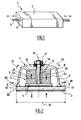
- FIG. 1 schematically represents an embodiment possible of a valve control device 1 comprising a housing external 2 in which is arranged a rod 3 along an axis substantially longitudinal to the housing 2.
- Box 2 can have any shape, but is preferably of parallelepiped shape.
- the rod 3 is movable in translation along the longitudinal axis of the housing 2. At least one of its ends is connected to a valve included in a hydraulic circuit.
- the double arrows visible in Figure 1 represent the displacement of the rod 3 relative to the housing 2.
- the seal between the housing 2 and the rod 3 is provided by means 4 able to secure the rod 3 and the housing 2 in order to guarantee sealing, while ensuring freedom of movement of the rod 3 relative to the housing 2.
- the sealing means comprise for example a membrane 4 tightly surrounding the rod 3 and connected on the other hand to the housing 2.
- the membrane 4 is flexible and allows longitudinal displacement of rod 3 in case 2.
- Fluid flow during opening or closing more or less significant of the valve takes place for example around the housing 2.
- Rod actuation means 3 are included in the housing 2.
- FIG. 2 schematically represents a first mode of possible realization of the actuation means of the rod 3.
- the means actuation have a symmetry with respect to the passing plane 30 by the longitudinal axis of the rod 3. Consequently, we have shown on this figure that the upper half, relative to plane 30, means actuating.
- Figure 3 shows the whole system in section longitudinal.
- Figures 4a and 4b show part of the system actuation according to a perspective view.
- the actuating means comprise means 5 for longitudinal sliding of the rod 3.
- the means 5 comprise for example a part substantially in the form of thick parallelepiped plate 5 pierced with a hole and surrounding the rod 3.
- the rod 3 can indifferently have a symmetry of revolution or a square section.
- the means 5 are fixed relative to the housing 2, and are fixed to its internal walls.
- part 5 is fixed relative to the wall inside of the housing 2 by one of its sides parallel to the axis of the rod 3.
- Means for moving the rod 3 allow it to slide in the means 5.
- the means of displacement comprise means 6 for deformation of a structure 7 integral with the rod 3.
- the device 1 has two structures 7, extending on either side of the plane 30.
- the upper structure 7 substantially forms a gantry surrounding the central part of the rod 3, the ends of the rod 3 leaving the structure 7 and the housing 2 to actuate the valves.
- the structure 7 comprises an upper plate 10 extending, in rest position, substantially parallel to and at a distance from the axes of the rod 3 and of part 5.
- the upper plate 10 has substantially a parallelepiped shape extending substantially parallel to the upper surface of part 5. For greater clarity, this plate upper 10 has not been reported in Figures 4a and 4b.
- the structure 7 also includes lateral pushers 9 from material on the upper plate 10 and extending obliquely towards the rod 3.
- the ends 13 of the pushers 9 are made integral with the rod 3, and form, for example, connection blocks.
- Figures 4a and 4b represent two possible embodiments of the pushers 9.
- the cross section of the pushers narrows from the plate 10 towards the blocks 13.
- the cross section of the pushers 9 is constant and square. Still other embodiments are possible.
- the dimension along an axis perpendicular to Figures 2 and 3 of the plate 10 and pushers 9 can be the same. Sizing depends on the cross-section of the rod 3.
- Structure 7 has section 8 narrowing at junctions between the upper plate 10 and the oblique pushers 9, as well only between the oblique pushers 9 and the blocks 13.
- the narrowing of section 8 thus form places of great flexibility of the part 7, and thus form means of the hinge type.
- the deformation means 6 deform the structure 7, which displaces turn the rod 3 in the means 5.
- the means 6 comprise pavers in active materials 6a and 6b connected on the one hand to the external surface of the means 5, and on the other hand to the internal face of the upper plate 10 of the structure 7.
- the blocks 6a and 6b have indifferently a radial section with symmetry of revolution or square. Their ends rest on two flat walls.
- the first flat surface is the bottom wall of the plate upper 10.
- the second flat surface is the upper wall of the means 5.
- Prestressing means 11 make it possible to prestress the deformation means 6 between parts 5 and 7.
- the means prestressing include a threaded rod 11 cooperating with a nut 12 and a washer 14.
- the nut 12 presses the washer 14 on the external face of the upper plate 10, in order to prestress parts 7, 6 and 5 together.
- the active materials 6a and 6b can be of the electro-restrictive type, magneto-strictives or piezoelectric. They are advantageously in piezoelectric materials.
- the direction of elongation of the active materials 6a and 6b is normal to the axes of the rod 3 and of the hollow part 5. Similarly, the direction of elongation of active materials 6a and 6b is normal to the plate upper 10 of structure 7.
- the arrows 22 show the directions of elongation of the active materials 6a and 6b during a first feeding phase electric.
- the arrows 22 thus show that during a first phase supply, the active material 6a is positively elongated, while of this same phase, the active material 6b is not elongated or undergoes a negative elongation.
- This difference in elongation causes a pivoting of the plate upper 10 in a direction indicated by the arrows 21.
- This pivoting is made possible by the flexibility of the structure 7 thanks to the hinges 8.
- the pivoting of the upper plate 10 in turn causes a displacement of the oblique pushers 9.
- the displacement of the rod 3 is easily modulated by the amplitude of elongation of materials 6a and 6b, which makes it possible to have a modulation precise hydraulic flow in the circuit.
- the active materials 6a and 6b and the tensions supply of the different phases allow a stroke of the rod 3 with an amplitude of ⁇ 0.5 mm.
- the force exerted at the end of the rod 3 is equal to 50 NOT.
- the deformable structure 7 allows a large amplification of elongations of the active materials 6a and 6b.
- Figure 3 shows that, according to a variant of the mode embodiment of FIG. 2, the inside of the container is advantageously filled case 2 by a back pressure liquid 18, this liquid being non-aggressive for the actuating means of the rod 3.
- Figure 3 shows that bellows 15 are provided at at least one membrane 4 in order to allow the filling liquid to expand.
- At least one expansion chamber is provided for filling liquid 18.
- the expansion chamber has example a cutout 17 of part of the walls of the housing 2, this cutout being connected to the housing 2 by bellows 16. The expansion filling liquid 18 is thus allowed by the moving part 17.
- the bellows 15 of the membranes 4 are associated or not with one or several expansion chamber (s).
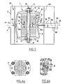
- FIG. 5 schematically represents a second mode of possible realization of the actuation means of the rod 3.
- the means actuation have a symmetry with respect to the passing plane 30 by the longitudinal axis of the rod 3.
- the rod 3 actuation is no longer arranged in the external housing 2, and the housing 2 no longer has internal sliding means.
- One end of the rod 3 is located on the left of the device of FIG. 5.
- the means of movement comprise means 6 for deformation of two structures 7, extending on either side of the plane 30 and perpendicular to the plates 10 of the structures 7, that is to say substantially parallel to an element of prestress 11 described in more detail later in the present description.
- the means 6 comprise at least two pavers made of active materials 6a and 6b.
- Each block 6a or 6b can have two blocks stacked on each other
- the active materials 6a and 6b can be of the electro-restrictive type, magneto-strictives or piezoelectric. They are advantageously in piezoelectric materials.
- the blocks 6a and 6b are polarized in the direction of the greatest dimension.
- Each structure 7 comprises an upper plate 10 extending, in the rest position, substantially parallel and at a distance from the plane 30.
- Each structure 7 also includes lateral pushers 9 coming from material on the upper plate 10 and extending obliquely towards the plane 30.
- the pushers 9 can also be attached to the plates 10 by means of at least one flexible, metallic or constructed blade in a material other than metal, the blade making the elastic connection between the pushers 9 and each plate 10.
- the pushers 9 are geometrically asymmetrical with respect to a longitudinal plane 31 passing through the prestressing means 11, the plane 31 being perpendicular to the plane of FIG. 5 and to the plates 10. They thus extend, starting from the plates 10 towards the rod 3, from the right towards the left side of the device in Figure 5.
- the means of prestressing preferably comprises a threaded rod 11 cooperating with a nut 12 and a washer 14.
- the nut 12 presses the washer 14 on the external face of the upper plate 10, in order to prestress the parts 7 and 6 together.
- the compression of the blocks 6a and 6b prevents their degradation.
- the prestressing means are flexible enough not to hinder the movement of the plates 10.
- the structures 7, symmetrical with respect to each other, are made integral with each other by means of blocks 13 located at one of the ends of the pushers 9.
- the pushers 9 are made integral with each other to form junction blocks 13.
- each pair of pushers 9 forms an angle whose opening is in the same direction - to the right on the figure 5 - but whose value can be different depending on the couple, as described in the remainder of this description.
- Each structure 7 has cross-sections of section 8 at junctions between the upper plate 10 and the oblique pushers 9, as well only between the oblique pushers 9 and the blocks 13.
- the narrowing of section 8 thus form places of great flexibility of the structure 7, and thus form means of the hinge type.
- the hinge 8 is formed by the connecting blade between the pusher 9 and the plate 10.
- connection blocks 13 are both connected to means connections to other mechanical parts that cross membranes 4 located to the right and left of the structures 7.
- the block 13a is movable longitudinally in the plane 30 and is connected to a connecting rod 55 which passes through the membrane 4a.
- Rod 55 is itself connected to the valve control rod 3.
- the block 13b is fixed relative to the housing 2 when using the device. It is connected to a rod 56 located in the axis of the rod 55 and in the axis of the rod 3 in the plane 30. The rod 56 passes through the membrane 4b.
- the rod 56 has at its end opposite the block 13b a head 57.
- the head 57 abuts against the end of a threaded rod 58 of a screw 60.
- the head 59 of the screw 60 is located outside of the housing 2.
- the screw 60 allows the establishment of the zero of the displacement of the rod 3. This setting zero of the rod displacement is effected by a displacement of the structures 7 in translation parallel to the plane 30.
- the structures 7 are floating in the case 2, but are connected inside the case 2 by through the membranes 4 allowing a translation of the structures 7 parallel to plane 30.
- the membranes 4 are flexible in the direction of movement of the rod 3 and stiff in the transverse direction.
- the 7 structures are not therefore not move in the transverse direction.
- the membrane 4a thus allows the displacement of the rod 55 and by consequently of the rod 3.
- the membrane 4a and the membrane 4b allow a displacement in translation of the structures 7 for zeroing the system.
- FIGS 6a and 6b schematically show modes of possible production of membranes 4 according to the invention. We see on these Figures that the membranes 4 do not necessarily seal the device.
- Sealing can indeed be provided elsewhere by other devices outside the housing 2.
- Figure 5 shows that the direction of elongation of the active materials 6a and 6b is normal to the axes of the rod 3 and the plates 10 of the structures 7.
- Figures 7a to 7c thus show three different states of extension blocks 6a and 6b, and consequently three different states of the rod 3.
- Figure 7a shows the initial state or position at rest of the device.
- the blocks 6a and 6b are not electrically powered.
- the two plates 10 are therefore parallel to each other, and parallel to the plane 30.
- the rod 3 is therefore in the zero position, which we recall that we can fix the position using the screw 60 which allows the structures 7 to be translated thanks to the flexibility in the longitudinal direction of the membranes 4a and 4b.
- the initial angle made between them the pushers 9 of two structures 7 is referred to by ⁇ 0.
- the initial distance between the blocks 13a and 13b is indicated by the lines 70.
- Figure 7b shows that the application of equal electric fields but opposite in sign on the two groups of blocks 6a and 6b will lead an inclination of the plates 10.
- the two plates 10 remain symmetrical between them with respect to plane 30.
- the inclination of the plates 10 results in a variation of the angles of the pushers 9 between them.
- the pair of pushers 9 connected to the block 13a forms an angle ⁇ 1 and the pair of pushers 9 connected to the block 13b forms an angle ⁇ 2 .
- the angles between the pushers change in opposition, that is to say that if ⁇ 1 decreases ⁇ 2 increases and vice versa, but the two angles ⁇ 1 and ⁇ 2 change by a different value.
- the arrows 22 show the directions of elongation of the active materials 6a and 6b during another phase of electrical supply, also shown in Figure 7c. Food is opposite to that of Figure 7b. The plates 10 will therefore be inclined in another direction, and block 13a will be moved to the right in Figure 7c.
- the evolution of the displacement distance of the block 13a as a function of the electrical supply can be approximated by a geometric relationship between the three angles ⁇ 0 , ⁇ 1 and ⁇ 2 . It is also influenced by the elastic deformations generated at the level of the structure when an external force is applied.
- the rod 3 is movable in translation along the longitudinal axis of the housing 2. At least one of its ends is connected to a valve included in a hydraulic circuit. We can for example adjust the pressure, the flow hydraulic fluid by moving the rod.
- the device can for example be used in servo drives brakes or in flight control actuators.
- the active materials 6a and 6b and the tensions supply of the different phases allow a stroke of the rod 3 with an amplitude of ⁇ 0.5 mm.
- the force generated by the system and exerted in end of rod 3 is equal to or greater than 50 N.
- the fact that the senses of elongation of the active materials 6a and 6b are antisymmetrical by relative to a longitudinal axis 31 to the rod 11 makes it possible to obtain a automatic compensation of neutral or equilibrium position. This compensation takes place whatever the temperature.
- the deformable structure 7 allows a large amplification of elongations of the active materials 6a and 6b.
- the inclination of one of the pairs of pushers 9 is reversed compared to that of the first mode of production.
- the second embodiment has a larger footprint reduces as well as a reduction in the number of interfaces in series with the active materials, which minimizes losses in the stiffness of interfaces. This increases the movement accuracy of the rod 3.
- the second embodiment can of course include a back pressure fluid and expansion bellows as in the first embodiment.
- the first embodiment may also include blades connection instead of section narrowing in the pushers 9. We have so nevertheless an elastic articulation without play which gives a flexibility at each structure 7.
- the device according to the invention has many advantages.
- the means allowing the deformation of the structure 7 include only 8 section narrowing. They don't include joints. Therefore, there is no wear of the parts nor appearance of games as and when used. So we have a good movement accuracy, as well as a long service life.
- the active materials 6a and 6b have a massive shape, which allows a high rigidity of the whole, as well as an effort important at stem outlet 3.
- the valve actuator therefore provides energy important for a small footprint of the system.
- the size according to the double arrow 32 is 50 mm.
- the overall dimensions of the device in the normal direction in plane 30 is also 50 mm, the part symmetrical to that shown in Figure 2 being included in this dimensioning. It is even more reduced for the second embodiment.
- the device comprises at least four pavers of active materials. This redundancy of the paving stones allows in addition to safety in the event of a malfunction of an active material pad. The system can still operate in the event of a block failure.
- the ceramics of the active materials are multilayer materials. They thus allow the use of a voltage low feeding.
Landscapes
- Engineering & Computer Science (AREA)
- General Engineering & Computer Science (AREA)
- Mechanical Engineering (AREA)
- Actuator (AREA)
- Multiple-Way Valves (AREA)
- Electrically Driven Valve-Operating Means (AREA)
- Micromachines (AREA)
- Diaphragms And Bellows (AREA)
Abstract
Description
- chaque structure comporte une plaque s'étendant sensiblement parallèlement à l'axe de déplacement de la pièce mobile et des poussoirs obliques venus de matière sur ladite plaque, au moins un couple de poussoirs étant solidaires de la pièce mobile à leur extrémité grâce à au moins un pavé de jonction ;
- chaque structure comporte des rétrécissements de section entre la plaque et les poussoirs obliques, ainsi qu'entre les poussoirs obliques et les pavés de jonction avec la pièce mobile, ces rétrécissements de section étant aptes à fournir une flexibilité à chaque structure ;
- chaque structure comporte une plaque s'étendant sensiblement parallèlement à l'axe de déplacement de la pièce mobile et des poussoirs obliques rapportés sur ladite plaque, au moins un couple de poussoirs étant solidaires de la pièce mobile à leur extrémité grâce à au moins un pavé de jonction, la liaison entre la plaque et les poussoirs et/ou la liaison entre les poussoirs et le pavé de jonction étant une articulation élastique sans jeu formée d'au moins une lame de liaison ;
- le dispositif comporte des moyens aptes à précontraindre les moyens de déplacement entre les plaques ;
- les poussoirs sont géométriquement antisymétriques par rapport à un plan perpendiculaire aux plaques ;
- un pavé de jonction est relié à la pièce mobile et l'autre pavé de jonction est fixe par rapport au boítier externe aux structures, le pavé fixe étant solidaire d'une tige venant en butée d'une vis de réglage de la position zéro de déplacement de la pièce mobile ;
- les poussoirs sont géométriquement symétriques par rapport à un plan perpendiculaire aux plaques ;
- les deux pavés de jonction sont reliés à la pièce mobile ;
- le dispositif comporte au moins une membrane de part et d'autre des pavés de jonction, les membranes étant souples dans la direction de déplacement de la pièce mobile et raides dans la direction transverse ;
- des membranes sont aptes à assurer une étanchéité entre la pièce mobile et le boítier ;
- le boítier est rempli d'un liquide de contre-pression ;
- au moins une membrane comporte des soufflets ;
- le dispositif comporte au moins une chambre de dilatation pour le liquide de remplissage ; et
- chaque chambre de dilatation comporte une découpe d'une partie des parois du boítier, cette découpe étant reliée au boítier par des soufflets. PRESENTATION DES FIGURES.
- la figure 1 représente schématiquement une vue en perspective d'un mode de réalisation possible d'un dispositif de commande de valves selon l'invention ;
- la figure 2 représente schématiquement une coupe longitudinale d'un mode de réalisation possible d'un dispositif de déplacement de valves, ce dispositif étant placé à l'intérieur du dispositif représenté à la figure 1 ;
- la figure 3 représente schématiquement une coupe longitudinale d'un mode de réalisation possible d'un dispositif de commande de valves comportant un liquide de remplissage à l'intérieur de son boítier, ce dispositif comportant des moyens permettant la dilatation thermique du liquide de remplissage ;
- la figure 4a représente schématiquement une vue en perspective d'un premier mode de réalisation possible d'une structure d'actionnement de la pièce mobile ;
- la figure 4b représente schématiquement une vue en perspective d'un deuxième mode de réalisation possible d'une structure d'actionnement de la pièce mobile ;
- la figure 5 représente schématiquement une coupe longitudinale d'un autre mode de réalisation possible d'un dispositif de déplacement de valves, ce dispositif étant placé à l'intérieur du dispositif représenté à la figure 1 ;
- les figures 6a et 6b représentent schématiquement un mode de réalisation d'une membrane fixée sur un dispositif selon la figure 5 ; et
- les figures 7a à 7c représentent différents états de fonctionnement d'un dispositif selon la figure 5.
Claims (15)
- Dispositif de déplacement d'une pièce (3) mobile selon un axe longitudinal par rapport à un boítier (2), ledit dispositif étant symétrique par rapport à un plan longitudinal (30) à la pièce mobile (3), comportant deux structures (7) solidaires de ladite pièce mobile (3) et des éléments en matériau actif comportant au moins deux pavés (6a, 6b) s'étendant entre des parois internes de chaque structure (7), les sens d'élongation des pavés étant antisymétriques par rapport à un axe (31) sensiblement perpendiculaire à la direction de déplacement de la pièce mobile (3), caractérisé en ce que les structures sont flexibles et sont aptes à déplacer la pièce mobile par leur déformation en fonction de l'élongation des pavés.
- Dispositif selon la revendication 1, caractérisé en ce que chaque structure (7) comporte une plaque (10) s'étendant sensiblement parallèlement à l'axe de déplacement de la pièce mobile et des poussoirs obliques (9) venus de matière sur ladite plaque (10), au moins un couple de poussoirs (9) étant solidaires de la pièce mobile (3) à leur extrémité grâce à au moins un pavé de jonction (13).
- Dispositif selon la revendication 2, caractérisé en ce que chaque structure (7) comporte des rétrécissements (8) de section entre la plaque (10) et les poussoirs obliques (9), ainsi qu'entre les poussoirs obliques et les pavés (13) de jonction avec la pièce mobile (3), ces rétrécissements (8) de section étant aptes à fournir une flexibilité à chaque structure (7).
- Dispositif selon la revendication 1, caractérisé en ce que chaque structure (7) comporte une plaque (10) s'étendant sensiblement parallèlement à l'axe de déplacement de la pièce mobile et des poussoirs obliques (9) rapportés sur ladite plaque (10), au moins un couple de poussoirs (9) étant solidaires de la pièce mobile (3) à leur extrémité grâce à au moins un pavé de jonction (13), la liaison entre la plaque (10) et les poussoirs (9) et/ou la liaison entre les poussoirs (9) et le pavé de jonction (13) étant une articulation élastique sans jeu formée d'au moins une lame de liaison.
- Dispositif selon l'une des revendications 1 à 4, caractérisé en ce qu'il comporte des moyens (11) aptes à précontraindre les moyens de déplacement entre les plaques (10).
- Dispositif selon l'une des revendications 1 à 5, caractérisé en ce que les poussoirs (9) sont géométriquement antisymétriques par rapport à un plan perpendiculaire aux plaques (10).
- Dispositif selon la revendication 6, caractérisé en ce qu'un pavé de jonction (13a) est relié à la pièce mobile (3) et l'autre pavé (13b) de jonction est fixe par rapport au boítier (2) externe aux structures (7), le pavé fixe (13b) étant solidaire d'une tige (56) venant en butée d'une vis (60) de réglage de la position zéro de déplacement de la pièce mobile (3).
- Dispositif selon l'une des revendications 1 à 5, caractérisé en ce que les poussoirs (9) sont géométriquement symétriques par rapport à un plan perpendiculaire aux plaques (10).
- Dispositif selon la revendication 8, caractérisé en ce que les deux pavés de jonction (13) sont reliés à la pièce mobile (3).
- Dispositif selon l'une des revendications 1 à 9, caractérisé en ce qu'il comporte au moins une membrane (4) de part et d'autre des pavés de jonction (13a, 13b), les membranes (4) étant souples dans la direction de déplacement de la pièce mobile (3) et raides dans la direction transverse.
- Dispositif selon la revendication 10, caractérisé en ce que des membranes sont aptes à assurer une étanchéité entre la pièce mobile (3) et le boítier (2).
- Dispositif selon la revendication 11, caractérisé en ce que le boítier (2) est rempli d'un liquide (18) de contre-pression.
- Dispositif selon l'une des revendications 10 à 12, caractérisé en ce que au moins une membrane comporte des soufflets (15).
- Dispositif selon l'une des revendications 10 à 13, caractérisé en ce qu'il comporte au moins une chambre de dilatation pour le liquide de remplissage (18).
- Dispositif selon la revendication 14, caractérisé en ce que chaque chambre de dilatation comporte une découpe (17) d'une partie des parois du boítier (2), cette découpe étant reliée au boítier (2) par des soufflets (16).
Applications Claiming Priority (2)
| Application Number | Priority Date | Filing Date | Title |
|---|---|---|---|
| FR0212230 | 2002-10-03 | ||
| FR0212230A FR2845440B1 (fr) | 2002-10-03 | 2002-10-03 | Dispositif de commande de valves |
Publications (2)
| Publication Number | Publication Date |
|---|---|
| EP1406319A1 true EP1406319A1 (fr) | 2004-04-07 |
| EP1406319B1 EP1406319B1 (fr) | 2008-07-23 |
Family
ID=31985413
Family Applications (1)
| Application Number | Title | Priority Date | Filing Date |
|---|---|---|---|
| EP03292446A Expired - Lifetime EP1406319B1 (fr) | 2002-10-03 | 2003-10-03 | Dispositif de commande de valves |
Country Status (5)
| Country | Link |
|---|---|
| US (2) | US7026746B2 (fr) |
| EP (1) | EP1406319B1 (fr) |
| CA (1) | CA2443002C (fr) |
| DE (1) | DE60322317D1 (fr) |
| FR (1) | FR2845440B1 (fr) |
Cited By (1)
| Publication number | Priority date | Publication date | Assignee | Title |
|---|---|---|---|---|
| EP2674721A3 (fr) * | 2012-06-15 | 2017-11-01 | The Boeing Company | Structure d'amplification de contrainte et actionneur de jet synthétique |
Families Citing this family (37)
| Publication number | Priority date | Publication date | Assignee | Title |
|---|---|---|---|---|
| US7166953B2 (en) * | 2001-03-02 | 2007-01-23 | Jon Heim | Electroactive polymer rotary clutch motors |
| US7161278B2 (en) * | 2003-10-31 | 2007-01-09 | Piezomotor Uppsala Ab | Peristaltic electromechanical actuator |
| WO2007012359A1 (fr) * | 2005-07-28 | 2007-02-01 | Etel Sa | Dispositif de freinage pour un moteur electrique |
| JP2007053826A (ja) * | 2005-08-15 | 2007-03-01 | Fujinon Corp | アクチュエータ |
| US7348710B2 (en) * | 2005-11-01 | 2008-03-25 | Piezomotor Uppsala Ab | Robust electromechanical motor |
| EP2013965B1 (fr) * | 2005-12-12 | 2010-09-08 | Richter, Berta | Moteur piézoélectrique utilisé comme système de propulsion de véhicule, servomoteur et analogue |
| US7462976B2 (en) * | 2006-01-03 | 2008-12-09 | Parker-Hannifin Corporation | Smart material actuator |
| US7471030B2 (en) * | 2006-03-08 | 2008-12-30 | Dynamic Structures And Materials, Llc | Spring biasing locking mechanism for step and repeat motors |
| JP4884050B2 (ja) * | 2006-03-30 | 2012-02-22 | 富士フイルム株式会社 | 駆動装置 |
| SE531053C2 (sv) * | 2007-05-24 | 2008-12-02 | Cochlear Ltd | Vibrator |
| US7952261B2 (en) * | 2007-06-29 | 2011-05-31 | Bayer Materialscience Ag | Electroactive polymer transducers for sensory feedback applications |
| US20090250021A1 (en) * | 2007-10-02 | 2009-10-08 | Artificial Muscle, Inc. | Fluid control systems employing compliant electroactive materials |
| US20090248085A1 (en) * | 2008-03-31 | 2009-10-01 | Cochlear Limited | Tissue injection fixation system for a prosthetic device |
| WO2010051797A2 (fr) * | 2008-11-10 | 2010-05-14 | Richter, Berta | Entraînement universel électrique de piézomoteur |
| DE102009013849A1 (de) * | 2009-03-18 | 2010-09-30 | Forschungszentrum Jülich GmbH | Vorrichtung und Verfahren zur elektromechanischen Positionierung |
| DE102009014770A1 (de) * | 2009-03-25 | 2010-09-30 | Cochlear Ltd., Lane Cove | Schwingungserzeuger |
| USRE48797E1 (en) | 2009-03-25 | 2021-10-26 | Cochlear Limited | Bone conduction device having a multilayer piezoelectric element |
| EP2239793A1 (fr) | 2009-04-11 | 2010-10-13 | Bayer MaterialScience AG | Montage de film polymère électrique commutable et son utilisation |
| JP5530528B2 (ja) * | 2009-11-10 | 2014-06-25 | マサチューセッツ インスティテュート オブ テクノロジー | 座屈型位相配列アクチュエータ |
| WO2012118916A2 (fr) | 2011-03-01 | 2012-09-07 | Bayer Materialscience Ag | Procédés de fabrication automatisés pour la production de dispositifs et de films polymères déformables |
| JP2014517331A (ja) | 2011-03-22 | 2014-07-17 | バイエル・インテレクチュアル・プロパティ・ゲゼルシャフト・ミット・ベシュレンクテル・ハフツング | 電場応答性高分子アクチュエータレンチキュラシステム |
| US9107013B2 (en) | 2011-04-01 | 2015-08-11 | Cochlear Limited | Hearing prosthesis with a piezoelectric actuator |
| US9876160B2 (en) | 2012-03-21 | 2018-01-23 | Parker-Hannifin Corporation | Roll-to-roll manufacturing processes for producing self-healing electroactive polymer devices |
| KR20150031285A (ko) | 2012-06-18 | 2015-03-23 | 바이엘 인텔렉쳐 프로퍼티 게엠베하 | 연신 공정을 위한 연신 프레임 |
| US9590193B2 (en) | 2012-10-24 | 2017-03-07 | Parker-Hannifin Corporation | Polymer diode |
| KR101386671B1 (ko) * | 2012-11-29 | 2014-04-21 | 인지컨트롤스 주식회사 | 피에조밸브 및 이를 위한 제조방법 |
| DE102014116295A1 (de) * | 2014-11-07 | 2016-05-12 | Bürkert Werke GmbH | Sitzventil |
| JP6539037B2 (ja) * | 2014-11-25 | 2019-07-03 | キヤノン株式会社 | 駆動装置 |
| DE112016002024B4 (de) * | 2015-06-25 | 2023-11-09 | Illinois Tool Works Inc. | Piezoaktortyp-ventil |
| GB201520124D0 (en) * | 2015-11-16 | 2015-12-30 | Delphi Internat Operations Luxembourg S À R L | Fuel injector |
| CN106015685B (zh) * | 2016-07-22 | 2018-09-18 | 北京控制工程研究所 | 一种适用于高压气体的压电比例调节阀 |
| DE102017216132B4 (de) * | 2017-09-13 | 2026-03-19 | Robert Bosch Gmbh | Dosiervorrichtung zum Steuern eines gasförmigen Mediums |
| JP7300117B2 (ja) * | 2019-06-28 | 2023-06-29 | 株式会社サタケ | 圧電式バルブ及び該圧電式バルブの製造方法 |
| CN110966444A (zh) * | 2019-08-09 | 2020-04-07 | 浙江中控自动化仪表有限公司 | 一种带压电堆的压电阀 |
| WO2021062697A1 (fr) * | 2019-09-30 | 2021-04-08 | 西门子(中国)有限公司 | Dispositif de frein de type bande, articulation de robot et robot collaboratif |
| CN111365507B (zh) * | 2020-04-16 | 2021-10-01 | 北京控制工程研究所 | 一种基于弹簧管位移放大的小型化高压压电比例阀 |
| FR3131615A1 (fr) * | 2022-01-06 | 2023-07-07 | Pytheas Technology | Valve comportant un actionneur piézoélectrique. |
Citations (4)
| Publication number | Priority date | Publication date | Assignee | Title |
|---|---|---|---|---|
| US6246552B1 (en) * | 1996-10-31 | 2001-06-12 | Tdk Corporation | Read/write head including displacement generating means that elongates and contracts by inverse piezoelectric effect of electrostrictive effect |
| US20010004181A1 (en) * | 1999-12-17 | 2001-06-21 | Peter Jaenker | Piezoelectric actuator system |
| DE10060018A1 (de) * | 2000-12-01 | 2002-06-13 | Daimler Chrysler Ag | Piezoelektrischer Aktuator |
| WO2003009402A2 (fr) * | 2001-07-17 | 2003-01-30 | Eads Deutschland Gmbh | Systeme d'actionneurs |
Family Cites Families (8)
| Publication number | Priority date | Publication date | Assignee | Title |
|---|---|---|---|---|
| US4534032A (en) * | 1982-09-30 | 1985-08-06 | Metalworking Lasers International Ltd. | Apparatus for establishing and maintaining a stable electrical discharge across a stream of gas, and a high-power laser including such apparatus |
| US5742561A (en) * | 1990-05-10 | 1998-04-21 | Northrop Grumman Corporation | Transversely driven piston transducer |
| US6545384B1 (en) * | 1997-02-07 | 2003-04-08 | Sri International | Electroactive polymer devices |
| DE19739594C2 (de) * | 1997-09-10 | 2001-09-06 | Daimler Chrysler Ag | Elektrostriktiver Stellantrieb |
| US6291928B1 (en) * | 1998-12-16 | 2001-09-18 | Active Control Experts, Inc. | High bandwidth, large stroke actuator |
| US6836056B2 (en) * | 2000-02-04 | 2004-12-28 | Viking Technologies, L.C. | Linear motor having piezo actuators |
| DE20004499U1 (de) * | 2000-03-14 | 2000-12-07 | DaimlerChrysler AG, 70567 Stuttgart | Aerodynamisches Strömungsprofil mit Vorderkantenklappe |
| DE10017332C2 (de) * | 2000-04-07 | 2002-04-18 | Daimler Chrysler Ag | Piezoelektrische Betätigungseinrichtung zur Klappensteuerung am Rotorblatt eines Hubschraubers |
-
2002
- 2002-10-03 FR FR0212230A patent/FR2845440B1/fr not_active Expired - Fee Related
-
2003
- 2003-10-02 CA CA2443002A patent/CA2443002C/fr not_active Expired - Fee Related
- 2003-10-03 DE DE60322317T patent/DE60322317D1/de not_active Expired - Lifetime
- 2003-10-03 US US10/678,580 patent/US7026746B2/en not_active Expired - Fee Related
- 2003-10-03 EP EP03292446A patent/EP1406319B1/fr not_active Expired - Lifetime
-
2006
- 2006-01-31 US US11/345,123 patent/US7205704B2/en not_active Expired - Fee Related
Patent Citations (4)
| Publication number | Priority date | Publication date | Assignee | Title |
|---|---|---|---|---|
| US6246552B1 (en) * | 1996-10-31 | 2001-06-12 | Tdk Corporation | Read/write head including displacement generating means that elongates and contracts by inverse piezoelectric effect of electrostrictive effect |
| US20010004181A1 (en) * | 1999-12-17 | 2001-06-21 | Peter Jaenker | Piezoelectric actuator system |
| DE10060018A1 (de) * | 2000-12-01 | 2002-06-13 | Daimler Chrysler Ag | Piezoelektrischer Aktuator |
| WO2003009402A2 (fr) * | 2001-07-17 | 2003-01-30 | Eads Deutschland Gmbh | Systeme d'actionneurs |
Cited By (2)
| Publication number | Priority date | Publication date | Assignee | Title |
|---|---|---|---|---|
| EP2674721A3 (fr) * | 2012-06-15 | 2017-11-01 | The Boeing Company | Structure d'amplification de contrainte et actionneur de jet synthétique |
| US10153420B2 (en) | 2012-06-15 | 2018-12-11 | The Boeing Company | Strain amplification structure and synthetic jet actuator |
Also Published As
| Publication number | Publication date |
|---|---|
| US20060125350A1 (en) | 2006-06-15 |
| FR2845440A1 (fr) | 2004-04-09 |
| EP1406319B1 (fr) | 2008-07-23 |
| CA2443002C (fr) | 2011-06-14 |
| CA2443002A1 (fr) | 2004-04-03 |
| FR2845440B1 (fr) | 2006-03-31 |
| US7026746B2 (en) | 2006-04-11 |
| DE60322317D1 (de) | 2008-09-04 |
| US7205704B2 (en) | 2007-04-17 |
| US20050006981A1 (en) | 2005-01-13 |
Similar Documents
| Publication | Publication Date | Title |
|---|---|---|
| EP1406319B1 (fr) | Dispositif de commande de valves | |
| EP2122703B1 (fr) | Dispositif piézoélectrique autonome de génération d'une tension électrique | |
| FR2765634A1 (fr) | Element de compensation des variations de longueur d'un objet sous l'effet de la temperature | |
| FR2836536A1 (fr) | Vanne piezoelectrique | |
| EP1890655A1 (fr) | Dispositif apte a etre intercale entre deux vertebres consecutives | |
| EP0610124B1 (fr) | Système d'assemblage de deux constituants d'une prothèse | |
| EP0898551B1 (fr) | Systeme de blocage temporaire de deplacement de deux corps l'un par rapport a l'autre, suivant au moins un sens d'une direction predeterminee | |
| FR2730766A1 (fr) | Actionneur thermique double effet a grande course | |
| EP4428430B1 (fr) | Réservoir comprenant des enceintes interne et externe ainsi qu au moins un système de liaison linéaire annulaire reliant lesdites enceintes | |
| EP0313470B1 (fr) | Bielle à contact, pour commandes de vol d'aérodynes | |
| EP3278168B1 (fr) | Actuateur electromecanique pour miroir deformable | |
| CH447654A (fr) | Instrument de mesure de forces | |
| EP0549390A1 (fr) | Vanne à joint rétractable à double élasticité | |
| EP1925959B1 (fr) | Miroir actif à actionneurs d'application de micro effort | |
| WO2022189752A1 (fr) | Outil de construction d'une paroi d'une cuve étanche et thermiquement isolante | |
| FR3071555B1 (fr) | Dispositif ameliore d'orientation d'engins spatiaux | |
| EP4414133A1 (fr) | Dispositif outil de réalisation d'un serrage axial à base d'un alliage à mémoire de forme | |
| FR3071552B1 (fr) | Dispositif ameliore d'amortissement d'engins spatiaux | |
| WO2025012570A1 (fr) | Vanne automatique ajustable | |
| WO2025012566A1 (fr) | Vanne pour fluide cryotechnique | |
| FR3005330A1 (fr) | Dispositif de commande hydraulique, notamment avec retour d'effort | |
| WO2003036077A1 (fr) | Dispositif de fixation d'un moyen de rupture d'impedance acoustique sur une tige | |
| EP1541913A1 (fr) | Dispositif de contrôle de flux autorégulé | |
| BE477977A (fr) | ||
| FR2618593A1 (fr) | Contacteur haute pression comprenant un organe de rappel perfectionne |
Legal Events
| Date | Code | Title | Description |
|---|---|---|---|
| PUAI | Public reference made under article 153(3) epc to a published international application that has entered the european phase |
Free format text: ORIGINAL CODE: 0009012 |
|
| AK | Designated contracting states |
Kind code of ref document: A1 Designated state(s): AT BE BG CH CY CZ DE DK EE ES FI FR GB GR HU IE IT LI LU MC NL PT RO SE SI SK TR |
|
| AX | Request for extension of the european patent |
Extension state: AL LT LV MK |
|
| 17P | Request for examination filed |
Effective date: 20040618 |
|
| AKX | Designation fees paid |
Designated state(s): DE ES GB IT |
|
| 17Q | First examination report despatched |
Effective date: 20050317 |
|
| RAP1 | Party data changed (applicant data changed or rights of an application transferred) |
Owner name: SAGEM DEFENSE SECURITE |
|
| 17Q | First examination report despatched |
Effective date: 20050317 |
|
| GRAP | Despatch of communication of intention to grant a patent |
Free format text: ORIGINAL CODE: EPIDOSNIGR1 |
|
| GRAS | Grant fee paid |
Free format text: ORIGINAL CODE: EPIDOSNIGR3 |
|
| GRAA | (expected) grant |
Free format text: ORIGINAL CODE: 0009210 |
|
| AK | Designated contracting states |
Kind code of ref document: B1 Designated state(s): DE ES GB IT |
|
| REG | Reference to a national code |
Ref country code: GB Ref legal event code: FG4D Free format text: NOT ENGLISH |
|
| REF | Corresponds to: |
Ref document number: 60322317 Country of ref document: DE Date of ref document: 20080904 Kind code of ref document: P |
|
| PG25 | Lapsed in a contracting state [announced via postgrant information from national office to epo] |
Ref country code: ES Free format text: LAPSE BECAUSE OF FAILURE TO SUBMIT A TRANSLATION OF THE DESCRIPTION OR TO PAY THE FEE WITHIN THE PRESCRIBED TIME-LIMIT Effective date: 20081103 |
|
| PLBE | No opposition filed within time limit |
Free format text: ORIGINAL CODE: 0009261 |
|
| STAA | Information on the status of an ep patent application or granted ep patent |
Free format text: STATUS: NO OPPOSITION FILED WITHIN TIME LIMIT |
|
| 26N | No opposition filed |
Effective date: 20090424 |
|
| PG25 | Lapsed in a contracting state [announced via postgrant information from national office to epo] |
Ref country code: IT Free format text: LAPSE BECAUSE OF FAILURE TO SUBMIT A TRANSLATION OF THE DESCRIPTION OR TO PAY THE FEE WITHIN THE PRESCRIBED TIME-LIMIT Effective date: 20080723 |
|
| PGFP | Annual fee paid to national office [announced via postgrant information from national office to epo] |
Ref country code: GB Payment date: 20160928 Year of fee payment: 14 |
|
| PGFP | Annual fee paid to national office [announced via postgrant information from national office to epo] |
Ref country code: DE Payment date: 20160922 Year of fee payment: 14 |
|
| REG | Reference to a national code |
Ref country code: DE Ref legal event code: R119 Ref document number: 60322317 Country of ref document: DE |
|
| GBPC | Gb: european patent ceased through non-payment of renewal fee |
Effective date: 20171003 |
|
| PG25 | Lapsed in a contracting state [announced via postgrant information from national office to epo] |
Ref country code: DE Free format text: LAPSE BECAUSE OF NON-PAYMENT OF DUE FEES Effective date: 20180501 Ref country code: GB Free format text: LAPSE BECAUSE OF NON-PAYMENT OF DUE FEES Effective date: 20171003 |