EP1406132A1 - Mécanisme d'embrayage de chronographe - Google Patents
Mécanisme d'embrayage de chronographe Download PDFInfo
- Publication number
- EP1406132A1 EP1406132A1 EP02079166A EP02079166A EP1406132A1 EP 1406132 A1 EP1406132 A1 EP 1406132A1 EP 02079166 A EP02079166 A EP 02079166A EP 02079166 A EP02079166 A EP 02079166A EP 1406132 A1 EP1406132 A1 EP 1406132A1
- Authority
- EP
- European Patent Office
- Prior art keywords
- clutch
- spring
- control lever
- board
- mechanism according
- Prior art date
- Legal status (The legal status is an assumption and is not a legal conclusion. Google has not performed a legal analysis and makes no representation as to the accuracy of the status listed.)
- Granted
Links
- 230000008878 coupling Effects 0.000 title 1
- 238000010168 coupling process Methods 0.000 title 1
- 238000005859 coupling reaction Methods 0.000 title 1
- 125000006850 spacer group Chemical group 0.000 claims description 7
- 238000006073 displacement reaction Methods 0.000 claims description 2
- 238000004519 manufacturing process Methods 0.000 description 5
- 230000000903 blocking effect Effects 0.000 description 2
- 238000010276 construction Methods 0.000 description 2
- 230000001186 cumulative effect Effects 0.000 description 1
Images



Classifications
-
- G—PHYSICS
- G04—HOROLOGY
- G04B—MECHANICALLY-DRIVEN CLOCKS OR WATCHES; MECHANICAL PARTS OF CLOCKS OR WATCHES IN GENERAL; TIME PIECES USING THE POSITION OF THE SUN, MOON OR STARS
- G04B19/00—Indicating the time by visual means
- G04B19/02—Back-gearing arrangements between gear train and hands
-
- G—PHYSICS
- G04—HOROLOGY
- G04F—TIME-INTERVAL MEASURING
- G04F7/00—Apparatus for measuring unknown time intervals by non-electric means
- G04F7/04—Apparatus for measuring unknown time intervals by non-electric means using a mechanical oscillator
- G04F7/08—Watches or clocks with stop devices, e.g. chronograph
- G04F7/0823—Watches or clocks with stop devices, e.g. chronograph with couplings between the chronograph mechanism and the base movement
- G04F7/0828—Watches or clocks with stop devices, e.g. chronograph with couplings between the chronograph mechanism and the base movement acting in the plane of the movement
-
- G—PHYSICS
- G04—HOROLOGY
- G04F—TIME-INTERVAL MEASURING
- G04F7/00—Apparatus for measuring unknown time intervals by non-electric means
- G04F7/04—Apparatus for measuring unknown time intervals by non-electric means using a mechanical oscillator
- G04F7/08—Watches or clocks with stop devices, e.g. chronograph
Definitions
- the present invention relates to a chronograph clutch mechanism by means of a control lever designed on the one hand to avoid a blockage when moves from a stop position or a chronograph position to zero at a position on the other hand to precisely adjust the force exerted by the end of the lever by resorbing somehow the inevitable manufacturing tolerances at level of moving parts constituting said clutch control.
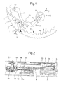
- FIGS. 1 and 2 schematically represent in plan and in cuts a clutch control in the running chronograph position.
- the clutch is actuated by a circular cam 1 having outside a drive toothing 3 on which acts a lever of actuation actuated by a pusher (not shown), said cam 1 being maintained in a determined position by means of a jumper 5.
- the cam 1 comprises inside a second control gear 2 whose teeth separating two hollows successive 4 teeth are truncated and have a flat surface 6.
- the teeth 3 has twice as many teeth as the internal toothing 2, so that the training of a step by actuation of a push button leads successively a hollow 4 and a flat 6 opposite a reference position determined.
- the clutch control 10 is constituted by a lever having basically three concurrent arms.
- a first arm 11 has its end pivoted in 12 in the plate 7 or in a plate of mechanism 8.
- a second arm 13 has at its end a tooth 14a held in abutment on a flat part 6 of the internal toothing of control 2 by a return spring 9 in abutment on a part 14
- a third flexible arm 15 has at its end a fork 16, preceded by a V-fold 18 having a plane 18a inclined against an edge 8a of 8.
- the object of the invention is therefore to remedy the two major drawbacks of the above-mentioned prior art by providing a chronograph watch having a clutch that is both reliable and easy to handle, and easily be adjusted at the end of the set-up to take into account the cumulative effect of manufacturing tolerances.
- the invention relates to a clutch mechanism of chronograph by means of a fork which controls the axial displacement of a clutch wheel to bring it to friction with an intermediate wheel second, or on the contrary to remove it from the force of a return spring.
- This fork is operated by a control lever which is reciprocated, but according to a first feature of the invention said fork is independent of the control lever contrary to what was exposed previously for the prior art.
- This fork is indeed formed in the big arm of an L-shaped curved element, hereinafter referred to as "clutch spring", articulated at the junction of both arms on the mechanism board or on a board of adjustment, the small arm of said clutch spring being biased at its base by the control lever.
- the clutch spring is articulated in a hinge of a control board formed by a plate of hinge, spacer and cover, assembled by two studs whose ends are guided in translation by oblong openings practiced in the mechanism board and in the chronograph bridge.
- the plate forming a spacer has an extension in which is formed a oblong opening having its major axis perpendicular to the alignment of the tenons, which allows by means of an eccentric to change the distance between the end of the small arm of the clutch spring and the end of the control lever, and thereby to compensate by means of a final adjustment the manufacturing tolerances of the different parts of the clutch.
- control lever comprises three concurrent branches, the first having its end rotated in a board of mechanism, the second having its end held by a return spring in bearing against the internal toothing of an annular cam comprising a succession of hollow and flats, and the end of the third to operate the small clutch spring arm.
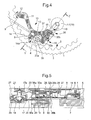
- FIG. 3 shows in top view only the elements components of the clutch mechanism, shown even more simplified but at more large scale in Figure 4, and in section in Figure 5.
- the clutch is shown in the disengaged position.
- clutch position change is controlled by an annular cam 1 rotated by a finger 26 actuated by a pusher (not shown) and acting on an external toothing 3, while being held in a position determined by a jumper 5.
- the cam 1 also has an internal toothing 2 formed of a succession of troughs 4 and flats 6.
- the ratio of steps between the internal toothing 2 and the external toothing 3 is 1/2 (for example 40 teeth to inside and 80 outside teeth), so that step advance of the cam 1 alternatively brings a recess 4 and a flat 6 opposite a position of reference.
- the clutch as such conventionally comprises a wheel intermediate second 19, engaged with the drive wheel 29 and the wheel of small second 25 and a clutch wheel 17, engaged with the chronograph wheel 27 and having at its upper part a flange 17a against which a spring of annular blade return 21 to hold the two mobiles 17, 19 in position engaged (as shown in Figure 7) when no solicitation exists exterior.
- the mechanism for acting on the clutch to move it into the disengaged position by exerting pressure under the collar 17a, comprises three essential elements, namely, a control lever 10, a 20 clutch spring L and an adjustment board 30.
- the control lever 10 shown in halftone in FIG. show the outline, has three concurrent branches 11, 13 and 15.
- the branch 11 is pivoted at 12 in the plate 7.
- the branch 13 has at one end a fold 14 Z terminated by a tooth 14a held against the internal toothing 2 of the cam 1 by a return spring 9 bearing against the vertical portion of the fold 14.
- This Z-fold of the end 14 is imposed only by the location of the mobile and other parts of the chronograph movement taken as an example, but could equally be replaced by any other type of stop, such as a simple rib.
- Branch 15 has its end perpendicular to a radial direction of the axis of rotation of the mobiles 17, 19 of the clutch, but not has no fork. It will be observed that the particular form of each lever arm 10 depends solely on the chosen location or imposed for the other mobiles constituting the chronograph movement, and that any other form within the reach of the person skilled in the art would still be within the scope of the present invention.
- the clutch spring 20 comprises a large arm 22 in which is formed the fork and a small arm 24 whose end is urged by the end of the branch 15 of the control lever 10.
- the clutch spring 20 comprises of other of the junction line of the two arms 22, 24 two small pivots 23a, 23b (visible in FIG. 9) mounted in a hinge of an adjustment board 30 of which the construction will be described in more detail below.
- this clutch spring 20 could be fixed directly on the mechanism board 8, or on a part secured thereto.
- the adjusting board 30 is formed by the stack of two elements 31, 35 arranged on either side of a third element forming a spacer 33.
- the element 31 has near the edges of one of its ends two small extensions 31 a, 31 b extending beyond the edge of the spacer 33, said extensions 31a, 31b having ends turned at right angles.
- the lid member is provided with one extended ends of two legs 35a, 35b located between the parts curved extensions 31a, 31b, said legs extending slightly beyond said extensions 31a, 31b.
- These three elements 31, 33, 35 are assembled by two tenons 32a, 32b driven through holes provided in said elements, the heads said tenons 32a, 32b protruding on either side of the stack to constitute the guide means 32.
- the tenons 32a, 32b are guided by openings oblong 36a, 36b made in the mechanism board 8 and in the bridge of chronograph 28, which limits the fretting of the adjustment board 30.
- the spacer 33 is provided with an extension 37 having an oblong opening 37a whose large axis is perpendicular to the alignment of tenons 32a, 32b.
- the oblong opening 37a is intended to receive an eccentric 38 which will allow to move the adjustment plate 30, and thereby to adjust the pressure exerted by the end of the branch 15 of the control lever 10 on the end of the small arm 24 of the clutch spring 20.
- extension 37 also has an orientation perpendicular to the alignment of 32a, 32b, but it is obvious that said extension could have a whole other orientation in so far as the long axis of the oblong opening remains perpendicular to the alignment of the guide pins.
- This construction has two main advantages. By acting example on the thicknesses, it makes it possible to have both a rigid control and not deformable and a clutch spring 20 having a certain flexibility to avoid too much friction.
- the board adjustment 30 makes it possible to compensate for the inevitable manufacturing tolerances in particular at the level of the clutch spring 20, the annular leaf spring 21 and cam 1. As we know, being able to be a little less demanding at the level of tolerances it is possible to manufacture the same product with a slightly lower cost while having, thanks to the invention a high quality.
Landscapes
- Physics & Mathematics (AREA)
- General Physics & Mathematics (AREA)
- Measurement Of Unknown Time Intervals (AREA)
- Springs (AREA)
Abstract
Description
- la figure 1 représente en vue de dessus un embrayage de l'art antérieur;
- la figure 2 est une représentation en coupe de la figure 1 selon la ligne II;
- la figure 3 représente en vue de dessus le mécanisme d'une montre chronographe dont le mécanisme est limité à l'embrayage selon l'invention;
- la figure 4 est une vue agrandie des pièces constituant l'embrayage en position stop ou chronographe à zéro;
- la figure 5 est une représentation en coupe brisée interrompue de la figure 4 selon les lignes V-V;
- la figure 6 correspond à la figure 4 lorsque l'embrayage est en position chronographe en marche;
- la figure 7 est une représentation en coupe brisée interrompue de la figure 6 selon les lignes VII-VII;
- la figure 8 est une représentation en perspective de la planche de réglage du mécanisme d'embrayage;
- la figure 9 est une vue de dessus de la planche de réglage représentée à la figure 8, et
- la figure 10 est une coupe du mécanisme de la figure 8 selon la ligne X-X.
Claims (7)
- Mécanisme d'embrayage de chronographe au moyen d'une fourche (16) commandant le déplacement axial d'une roue d'embrayage (17) pour l'amener à friction avec une roue intermédiaire de secondes (19), ou au contraire l'en écarter contre la force d'un ressort de rappel (21), ladite fourche (16) étant actionnée par un levier de commande (10) effectuant un mouvement de va-et-vient, caractérisé en ce que le mécanisme comporte un ressort d'embrayage (20) sensiblement en L, indépendant du levier de commande (10) et articulé à la jonction de ses bras (22, 24) sur la planche de mécanisme (8) ou sur une planche de réglage (20), le grand bras (22) dudit ressort d'embrayage (20) comportant la fourche (16) et le petit bras (24) étant actionnable par une extrémité du levier de commande (10).
- Mécanisme d'embrayage selon la revendication 1, caractérisé en ce que le ressort d'embrayage (20) est articulé sur une planche de réglage (30) comportant des moyens de guidage (32) et des moyens de positionnement (34) du petit bras (22) dudit ressort d'embrayage (20) par rapport à l'extrémité du petit bras (24).
- Mécanisme d'embrayage selon la revendication 2, caractérisé en ce que les moyens de guidage (32) sont constitués par deux tenons (32a, 32b) permettant à la planche de réglage (30) d'avoir un ébat limité par des ouvertures oblongues (36a, 36b) pratiquées dans la planche de mécanisme (8) et dans le pont de chronographe (28), lesdits tenons (32a, 32b) étant chassés à travers une plaque de charnière (31), une entretoise (33) et un couvercle (35), pour former ensemble à une extrémité la charnière du ressort d'embrayage (20).
- Mécanisme d'embrayage selon les revendications 2 et 3, caractérisé en ce que les moyens de positionnement (34) sont constitués par une extension (37) de l'entretoise (33) comportant une ouverture oblongue (37a) ayant son grand axe sensiblement perpendiculaire à l'alignement des tenons de guidage (32a, 32b), ladite ouverture oblongue (37a) étant destinée à recevoir un excentrique (38).
- Mécanisme d'embrayage selon la revendication 4, caractérisé en ce que l'extension (37) comportant les moyens de positionnement (34) est sensiblement perpendiculaire à l'alignement des tenons de guidage (32a, 32b).
- Mécanisme d'embrayage selon la revendication 1, caractérisé en ce que le levier de commande (10) comporte trois branches concourantes (11, 13, 15), la première (11) ayant son extrémité pivotée dans une planche de mécanisme (8), la deuxième (13) ayant son extrémité (14a) maintenue par un ressort de rappel (9) en appui contre la denture intérieure (2) d'une came annulaire (1) comportant une succession de creux (4) et de méplats (6), et l'extrémité de la troisième (15) permettant d'actionner le petit bras (24) du ressort d'embrayage (20).
- Mécanisme d'embrayage selon la revendication 6, caractérisé en ce que la deuxième branche (13) du levier de commande (10) a son extrémité recourbée en Z pour former la butée du ressort de rappel (9).
Priority Applications (3)
| Application Number | Priority Date | Filing Date | Title |
|---|---|---|---|
| DE60210973T DE60210973T2 (de) | 2002-10-04 | 2002-10-04 | Kupplungsmechanismus für Chronographen |
| EP02079166A EP1406132B1 (fr) | 2002-10-04 | 2002-10-04 | Mécanisme d'embrayage de chronographe |
| AT02079166T ATE324621T1 (de) | 2002-10-04 | 2002-10-04 | Kupplungsmechanismus für chronographen |
Applications Claiming Priority (2)
| Application Number | Priority Date | Filing Date | Title |
|---|---|---|---|
| CH16622002 | 2002-10-04 | ||
| EP02079166A EP1406132B1 (fr) | 2002-10-04 | 2002-10-04 | Mécanisme d'embrayage de chronographe |
Publications (2)
| Publication Number | Publication Date |
|---|---|
| EP1406132A1 true EP1406132A1 (fr) | 2004-04-07 |
| EP1406132B1 EP1406132B1 (fr) | 2006-04-26 |
Family
ID=32034714
Family Applications (1)
| Application Number | Title | Priority Date | Filing Date |
|---|---|---|---|
| EP02079166A Expired - Lifetime EP1406132B1 (fr) | 2002-10-04 | 2002-10-04 | Mécanisme d'embrayage de chronographe |
Country Status (9)
| Country | Link |
|---|---|
| US (1) | US7021818B2 (fr) |
| EP (1) | EP1406132B1 (fr) |
| JP (1) | JP4343642B2 (fr) |
| KR (1) | KR100972914B1 (fr) |
| CN (1) | CN100527021C (fr) |
| AT (1) | ATE324621T1 (fr) |
| DE (1) | DE60210973T2 (fr) |
| SG (1) | SG107155A1 (fr) |
| TW (1) | TWI269949B (fr) |
Cited By (1)
| Publication number | Priority date | Publication date | Assignee | Title |
|---|---|---|---|---|
| CN101452256B (zh) * | 2007-12-07 | 2012-05-16 | 奥米加股份有限公司 | 计时器控制装置 |
Families Citing this family (10)
| Publication number | Priority date | Publication date | Assignee | Title |
|---|---|---|---|---|
| JP5100523B2 (ja) * | 2008-06-16 | 2012-12-19 | セイコーインスツル株式会社 | 日表示装置及びこれを備えた時計 |
| EP2180383B1 (fr) * | 2008-10-24 | 2012-01-25 | ETA SA Manufacture Horlogère Suisse | Dispositif d'aide au maintien en position d'un disque indicateur de quantième pour pièce d'horlogerie |
| DE102013103180B4 (de) * | 2013-03-28 | 2014-11-13 | Uwe Heinz | Chronograph |
| CH709796A1 (fr) * | 2014-06-19 | 2015-12-31 | Société Anonyme De La Manufacture D Horlogerie Audemars Piguet & Cie | Dispositif d'embrayage basculant pour pièce d'horlogerie. |
| EP3147728A1 (fr) * | 2015-09-24 | 2017-03-29 | Harry Winston SA | Mécanisme de positionnement d'une roue dentée dans un mouvement horloger |
| EP3324249A1 (fr) * | 2016-11-17 | 2018-05-23 | Nogerah SA | Systeme d'embrayage pour chronographe |
| EP3489760B1 (fr) * | 2017-11-22 | 2020-08-26 | Harry Winston SA | Boîte d'horlogerie avec poussoir |
| EP3502803B1 (fr) * | 2017-12-19 | 2020-08-05 | Omega SA | Ensemble réglable d'horlogerie |
| EP3671367B1 (fr) * | 2018-12-21 | 2025-01-29 | ETA SA Manufacture Horlogère Suisse | Assemblage comprenant un support, une platine et des moyens de fixation, notamment pour une piece d'horlogerie |
| EP4296798B1 (fr) * | 2022-06-23 | 2025-03-12 | Blancpain SA | Mouvement d'horlogerie comportant un mécanisme de chronographe |
Citations (2)
| Publication number | Priority date | Publication date | Assignee | Title |
|---|---|---|---|---|
| CH678911GA3 (fr) * | 1990-04-12 | 1991-11-29 | ||
| EP1136894A1 (fr) * | 2000-03-20 | 2001-09-26 | DTH Dubois Technique Horlogère SA | Dispositif de retour à zéro d'un chronographe |
Family Cites Families (5)
| Publication number | Priority date | Publication date | Assignee | Title |
|---|---|---|---|---|
| CH596594B5 (fr) * | 1976-05-24 | 1978-03-15 | Ebauches Sa | |
| CH671492B5 (fr) | 1987-04-02 | 1990-03-15 | Roventa Henex Sa | |
| CH682034B5 (fr) * | 1991-10-14 | 1994-01-14 | Eta S.A. Fabriques D'ebauches | Pièce d'horlogerie comportant un module de chronographe adapté sur un module moteur. |
| JP3466160B2 (ja) | 2001-03-14 | 2003-11-10 | セイコーインスツルメンツ株式会社 | 復針レバーを備えたクロノグラフ時計 |
| DE60139155D1 (de) * | 2001-03-21 | 2009-08-13 | Glashuetter Uhrenbetrieb Gmbh | Chronograph mit zwei drehrichtungen |
-
2002
- 2002-10-04 DE DE60210973T patent/DE60210973T2/de not_active Expired - Lifetime
- 2002-10-04 EP EP02079166A patent/EP1406132B1/fr not_active Expired - Lifetime
- 2002-10-04 AT AT02079166T patent/ATE324621T1/de not_active IP Right Cessation
-
2003
- 2003-09-29 TW TW092126886A patent/TWI269949B/zh not_active IP Right Cessation
- 2003-10-01 KR KR1020030068112A patent/KR100972914B1/ko not_active Expired - Fee Related
- 2003-10-02 SG SG200305760A patent/SG107155A1/en unknown
- 2003-10-03 JP JP2003345467A patent/JP4343642B2/ja not_active Expired - Lifetime
- 2003-10-06 US US10/678,157 patent/US7021818B2/en not_active Expired - Lifetime
- 2003-10-08 CN CNB2003101007495A patent/CN100527021C/zh not_active Expired - Lifetime
Patent Citations (2)
| Publication number | Priority date | Publication date | Assignee | Title |
|---|---|---|---|---|
| CH678911GA3 (fr) * | 1990-04-12 | 1991-11-29 | ||
| EP1136894A1 (fr) * | 2000-03-20 | 2001-09-26 | DTH Dubois Technique Horlogère SA | Dispositif de retour à zéro d'un chronographe |
Cited By (1)
| Publication number | Priority date | Publication date | Assignee | Title |
|---|---|---|---|---|
| CN101452256B (zh) * | 2007-12-07 | 2012-05-16 | 奥米加股份有限公司 | 计时器控制装置 |
Also Published As
| Publication number | Publication date |
|---|---|
| CN100527021C (zh) | 2009-08-12 |
| DE60210973D1 (de) | 2006-06-01 |
| TWI269949B (en) | 2007-01-01 |
| TW200405959A (en) | 2004-04-16 |
| JP4343642B2 (ja) | 2009-10-14 |
| DE60210973T2 (de) | 2007-01-04 |
| HK1063221A1 (zh) | 2004-12-17 |
| KR20040031598A (ko) | 2004-04-13 |
| KR100972914B1 (ko) | 2010-07-28 |
| US20040066711A1 (en) | 2004-04-08 |
| SG107155A1 (en) | 2004-11-29 |
| US7021818B2 (en) | 2006-04-04 |
| EP1406132B1 (fr) | 2006-04-26 |
| JP2004125797A (ja) | 2004-04-22 |
| CN1497400A (zh) | 2004-05-19 |
| ATE324621T1 (de) | 2006-05-15 |
Similar Documents
| Publication | Publication Date | Title |
|---|---|---|
| EP1406132B1 (fr) | Mécanisme d'embrayage de chronographe | |
| WO2001021022A1 (fr) | Dispositif de verrouillage d'une position d'une piece mobile par rapport a une piece fixe | |
| EP1431845A1 (fr) | Boíte de montre | |
| EP3882422B1 (fr) | Verrou pour panneau d'aéronef | |
| EP2048548A2 (fr) | Marteau pour mécanisme d'horlogerie, mécanisme d'horlogerie, notamment mécanisme de sonnerie, en étant équipé, et pièce d'horlogerie les comportant | |
| WO2021205039A1 (fr) | Volant de vehicule avec structure mobile et dispositif de blocage | |
| FR2849817A1 (fr) | Retroviseur pour vehicule comportant un miroir monte pivotant sur deux axes perpendiculaires | |
| CH698827B1 (fr) | Dispositif de remise à zéro pour une pièce d'horlogerie. | |
| EP2945029B1 (fr) | Dispositif de verrouillage pour chronographe | |
| FR2915436A1 (fr) | Mecanisme d'articulation et siege de vehicule comportant un tel mecanisme. | |
| FR2893557A1 (fr) | Dispositif d'inclinaison de siege de vehicule | |
| EP1867518A1 (fr) | Dispositif de réglage en hauteur d'un siège blocable en position et siège équipé du dispositif. | |
| EP2054780A2 (fr) | Dispositif de commande pour piece d'horlogerie | |
| FR3103642A1 (fr) | Appareillage à support d’appareillage basculant | |
| EP1890205B1 (fr) | Dispositif de remise à zéro pour une pièce d'horlogerie | |
| FR2493001A1 (fr) | Dispositif de commande coulissant pour montre | |
| WO2014016499A1 (fr) | Saxophone a actionnement de mecanisme de commande d'octave ameliore | |
| EP4511703B1 (fr) | Organe de commande d'au moins une fonction d'un mouvement horloger | |
| FR2756230A1 (fr) | Dispositif d'actionnement d'un organe de commande d'un mecanisme de siege de vehicule automobile et siege muni d'un tel dispositif | |
| FR2971748A1 (fr) | Ensemble d'articulation renforce et siege de vehicule comportant un tel ensemble | |
| EP4733855A1 (fr) | Mecanisme horloger comprenant un dispositif de selection de position d'un organe fonctionnel | |
| EP1046963B1 (fr) | Mécanisme à bouton-poussoir et pièce d'horlogerie munie de tels mécanismes | |
| EP3829014B1 (fr) | Appareillage avec un support d'appareillage basculant et un systeme de verrouillage debrayable au moyen d'une touche d'actionnement basculante | |
| EP3650953B1 (fr) | Mecanisme horloger comprenant une etoile et un ressort-sautoir | |
| EP0014640B1 (fr) | Programmateur à trois temporisations mécaniques |
Legal Events
| Date | Code | Title | Description |
|---|---|---|---|
| PUAI | Public reference made under article 153(3) epc to a published international application that has entered the european phase |
Free format text: ORIGINAL CODE: 0009012 |
|
| AK | Designated contracting states |
Kind code of ref document: A1 Designated state(s): AT BE BG CH CY CZ DE DK EE ES FI FR GB GR IE IT LI LU MC NL PT SE SK TR |
|
| AX | Request for extension of the european patent |
Extension state: AL LT LV MK RO SI |
|
| 17P | Request for examination filed |
Effective date: 20041007 |
|
| AKX | Designation fees paid |
Designated state(s): AT BE BG CH CY CZ DE DK EE ES FI FR GB GR IE IT LI LU MC NL PT SE SK TR |
|
| 17Q | First examination report despatched |
Effective date: 20050110 |
|
| GRAP | Despatch of communication of intention to grant a patent |
Free format text: ORIGINAL CODE: EPIDOSNIGR1 |
|
| GRAS | Grant fee paid |
Free format text: ORIGINAL CODE: EPIDOSNIGR3 |
|
| GRAA | (expected) grant |
Free format text: ORIGINAL CODE: 0009210 |
|
| AK | Designated contracting states |
Kind code of ref document: B1 Designated state(s): AT BE BG CH CY CZ DE DK EE ES FI FR GB GR IE IT LI LU MC NL PT SE SK TR |
|
| PG25 | Lapsed in a contracting state [announced via postgrant information from national office to epo] |
Ref country code: SK Free format text: LAPSE BECAUSE OF FAILURE TO SUBMIT A TRANSLATION OF THE DESCRIPTION OR TO PAY THE FEE WITHIN THE PRESCRIBED TIME-LIMIT Effective date: 20060426 Ref country code: AT Free format text: LAPSE BECAUSE OF FAILURE TO SUBMIT A TRANSLATION OF THE DESCRIPTION OR TO PAY THE FEE WITHIN THE PRESCRIBED TIME-LIMIT Effective date: 20060426 Ref country code: GB Free format text: LAPSE BECAUSE OF FAILURE TO SUBMIT A TRANSLATION OF THE DESCRIPTION OR TO PAY THE FEE WITHIN THE PRESCRIBED TIME-LIMIT Effective date: 20060426 Ref country code: NL Free format text: LAPSE BECAUSE OF FAILURE TO SUBMIT A TRANSLATION OF THE DESCRIPTION OR TO PAY THE FEE WITHIN THE PRESCRIBED TIME-LIMIT Effective date: 20060426 Ref country code: FI Free format text: LAPSE BECAUSE OF FAILURE TO SUBMIT A TRANSLATION OF THE DESCRIPTION OR TO PAY THE FEE WITHIN THE PRESCRIBED TIME-LIMIT Effective date: 20060426 Ref country code: IE Free format text: LAPSE BECAUSE OF FAILURE TO SUBMIT A TRANSLATION OF THE DESCRIPTION OR TO PAY THE FEE WITHIN THE PRESCRIBED TIME-LIMIT Effective date: 20060426 Ref country code: CZ Free format text: LAPSE BECAUSE OF FAILURE TO SUBMIT A TRANSLATION OF THE DESCRIPTION OR TO PAY THE FEE WITHIN THE PRESCRIBED TIME-LIMIT Effective date: 20060426 Ref country code: IT Free format text: LAPSE BECAUSE OF FAILURE TO SUBMIT A TRANSLATION OF THE DESCRIPTION OR TO PAY THE FEE WITHIN THE PRESCRIBED TIME-LIMIT;WARNING: LAPSES OF ITALIAN PATENTS WITH EFFECTIVE DATE BEFORE 2007 MAY HAVE OCCURRED AT ANY TIME BEFORE 2007. THE CORRECT EFFECTIVE DATE MAY BE DIFFERENT FROM THE ONE RECORDED. Effective date: 20060426 |
|
| REG | Reference to a national code |
Ref country code: GB Ref legal event code: FG4D Free format text: NOT ENGLISH |
|
| REG | Reference to a national code |
Ref country code: IE Ref legal event code: FG4D Free format text: LANGUAGE OF EP DOCUMENT: FRENCH |
|
| REF | Corresponds to: |
Ref document number: 60210973 Country of ref document: DE Date of ref document: 20060601 Kind code of ref document: P |
|
| PG25 | Lapsed in a contracting state [announced via postgrant information from national office to epo] |
Ref country code: DK Free format text: LAPSE BECAUSE OF FAILURE TO SUBMIT A TRANSLATION OF THE DESCRIPTION OR TO PAY THE FEE WITHIN THE PRESCRIBED TIME-LIMIT Effective date: 20060726 Ref country code: SE Free format text: LAPSE BECAUSE OF FAILURE TO SUBMIT A TRANSLATION OF THE DESCRIPTION OR TO PAY THE FEE WITHIN THE PRESCRIBED TIME-LIMIT Effective date: 20060726 |
|
| PG25 | Lapsed in a contracting state [announced via postgrant information from national office to epo] |
Ref country code: ES Free format text: LAPSE BECAUSE OF FAILURE TO SUBMIT A TRANSLATION OF THE DESCRIPTION OR TO PAY THE FEE WITHIN THE PRESCRIBED TIME-LIMIT Effective date: 20060806 |
|
| REG | Reference to a national code |
Ref country code: CH Ref legal event code: NV Representative=s name: ICB INGENIEURS CONSEILS EN BREVETS SA |
|
| PG25 | Lapsed in a contracting state [announced via postgrant information from national office to epo] |
Ref country code: PT Free format text: LAPSE BECAUSE OF FAILURE TO SUBMIT A TRANSLATION OF THE DESCRIPTION OR TO PAY THE FEE WITHIN THE PRESCRIBED TIME-LIMIT Effective date: 20060926 |
|
| PG25 | Lapsed in a contracting state [announced via postgrant information from national office to epo] |
Ref country code: MC Free format text: LAPSE BECAUSE OF NON-PAYMENT OF DUE FEES Effective date: 20061031 |
|
| NLV1 | Nl: lapsed or annulled due to failure to fulfill the requirements of art. 29p and 29m of the patents act | ||
| REG | Reference to a national code |
Ref country code: IE Ref legal event code: FD4D |
|
| GBV | Gb: ep patent (uk) treated as always having been void in accordance with gb section 77(7)/1977 [no translation filed] |
Effective date: 20060426 |
|
| PLBE | No opposition filed within time limit |
Free format text: ORIGINAL CODE: 0009261 |
|
| STAA | Information on the status of an ep patent application or granted ep patent |
Free format text: STATUS: NO OPPOSITION FILED WITHIN TIME LIMIT |
|
| 26N | No opposition filed |
Effective date: 20070129 |
|
| BERE | Be: lapsed |
Owner name: ETA SA MANUFACTURE HORLOGERE SUISSE Effective date: 20061031 |
|
| PG25 | Lapsed in a contracting state [announced via postgrant information from national office to epo] |
Ref country code: GR Free format text: LAPSE BECAUSE OF FAILURE TO SUBMIT A TRANSLATION OF THE DESCRIPTION OR TO PAY THE FEE WITHIN THE PRESCRIBED TIME-LIMIT Effective date: 20060727 |
|
| PG25 | Lapsed in a contracting state [announced via postgrant information from national office to epo] |
Ref country code: EE Free format text: LAPSE BECAUSE OF FAILURE TO SUBMIT A TRANSLATION OF THE DESCRIPTION OR TO PAY THE FEE WITHIN THE PRESCRIBED TIME-LIMIT Effective date: 20060426 Ref country code: BG Free format text: LAPSE BECAUSE OF FAILURE TO SUBMIT A TRANSLATION OF THE DESCRIPTION OR TO PAY THE FEE WITHIN THE PRESCRIBED TIME-LIMIT Effective date: 20060726 |
|
| PG25 | Lapsed in a contracting state [announced via postgrant information from national office to epo] |
Ref country code: TR Free format text: LAPSE BECAUSE OF FAILURE TO SUBMIT A TRANSLATION OF THE DESCRIPTION OR TO PAY THE FEE WITHIN THE PRESCRIBED TIME-LIMIT Effective date: 20060426 Ref country code: LU Free format text: LAPSE BECAUSE OF NON-PAYMENT OF DUE FEES Effective date: 20061004 |
|
| PG25 | Lapsed in a contracting state [announced via postgrant information from national office to epo] |
Ref country code: CY Free format text: LAPSE BECAUSE OF FAILURE TO SUBMIT A TRANSLATION OF THE DESCRIPTION OR TO PAY THE FEE WITHIN THE PRESCRIBED TIME-LIMIT Effective date: 20060426 |
|
| PG25 | Lapsed in a contracting state [announced via postgrant information from national office to epo] |
Ref country code: BE Free format text: LAPSE BECAUSE OF FAILURE TO SUBMIT A TRANSLATION OF THE DESCRIPTION OR TO PAY THE FEE WITHIN THE PRESCRIBED TIME-LIMIT Effective date: 20061031 |
|
| REG | Reference to a national code |
Ref country code: FR Ref legal event code: PLFP Year of fee payment: 14 |
|
| REG | Reference to a national code |
Ref country code: FR Ref legal event code: PLFP Year of fee payment: 15 |
|
| REG | Reference to a national code |
Ref country code: FR Ref legal event code: PLFP Year of fee payment: 16 |
|
| PGFP | Annual fee paid to national office [announced via postgrant information from national office to epo] |
Ref country code: FR Payment date: 20170921 Year of fee payment: 16 |
|
| PGFP | Annual fee paid to national office [announced via postgrant information from national office to epo] |
Ref country code: DE Payment date: 20170920 Year of fee payment: 16 |
|
| REG | Reference to a national code |
Ref country code: DE Ref legal event code: R119 Ref document number: 60210973 Country of ref document: DE |
|
| PG25 | Lapsed in a contracting state [announced via postgrant information from national office to epo] |
Ref country code: DE Free format text: LAPSE BECAUSE OF NON-PAYMENT OF DUE FEES Effective date: 20190501 |
|
| PG25 | Lapsed in a contracting state [announced via postgrant information from national office to epo] |
Ref country code: FR Free format text: LAPSE BECAUSE OF NON-PAYMENT OF DUE FEES Effective date: 20181031 |
|
| PGFP | Annual fee paid to national office [announced via postgrant information from national office to epo] |
Ref country code: CH Payment date: 20210921 Year of fee payment: 20 |
|
| REG | Reference to a national code |
Ref country code: CH Ref legal event code: PL |