EP1406020A2 - Vibrating pumping stage for vacuum pumps, and vacuum pump with vibrating pumping stages - Google Patents
Vibrating pumping stage for vacuum pumps, and vacuum pump with vibrating pumping stages Download PDFInfo
- Publication number
- EP1406020A2 EP1406020A2 EP03021648A EP03021648A EP1406020A2 EP 1406020 A2 EP1406020 A2 EP 1406020A2 EP 03021648 A EP03021648 A EP 03021648A EP 03021648 A EP03021648 A EP 03021648A EP 1406020 A2 EP1406020 A2 EP 1406020A2
- Authority
- EP
- European Patent Office
- Prior art keywords
- membrane
- pumping stage
- pumping
- vibrating
- supporting base
- Prior art date
- Legal status (The legal status is an assumption and is not a legal conclusion. Google has not performed a legal analysis and makes no representation as to the accuracy of the status listed.)
- Granted
Links
- 238000005086 pumping Methods 0.000 title claims abstract description 68
- 239000012528 membrane Substances 0.000 claims abstract description 72
- XUIMIQQOPSSXEZ-UHFFFAOYSA-N Silicon Chemical compound [Si] XUIMIQQOPSSXEZ-UHFFFAOYSA-N 0.000 claims abstract description 6
- 229910052710 silicon Inorganic materials 0.000 claims abstract description 6
- 239000010703 silicon Substances 0.000 claims abstract description 6
- 230000005684 electric field Effects 0.000 claims description 8
- 230000002093 peripheral effect Effects 0.000 claims description 7
- VYPSYNLAJGMNEJ-UHFFFAOYSA-N Silicium dioxide Chemical compound O=[Si]=O VYPSYNLAJGMNEJ-UHFFFAOYSA-N 0.000 claims description 6
- 239000000463 material Substances 0.000 claims description 4
- 229910052581 Si3N4 Inorganic materials 0.000 claims description 3
- 239000004411 aluminium Substances 0.000 claims description 3
- 229910052782 aluminium Inorganic materials 0.000 claims description 3
- XAGFODPZIPBFFR-UHFFFAOYSA-N aluminium Chemical compound [Al] XAGFODPZIPBFFR-UHFFFAOYSA-N 0.000 claims description 3
- 229910052681 coesite Inorganic materials 0.000 claims description 3
- 229910052906 cristobalite Inorganic materials 0.000 claims description 3
- 239000000377 silicon dioxide Substances 0.000 claims description 3
- 229910052682 stishovite Inorganic materials 0.000 claims description 3
- 229910052905 tridymite Inorganic materials 0.000 claims description 3
- ZOKXTWBITQBERF-UHFFFAOYSA-N Molybdenum Chemical compound [Mo] ZOKXTWBITQBERF-UHFFFAOYSA-N 0.000 claims description 2
- 239000011733 molybdenum Substances 0.000 claims description 2
- 229910052750 molybdenum Inorganic materials 0.000 claims description 2
- 239000000725 suspension Substances 0.000 claims description 2
- 239000000758 substrate Substances 0.000 abstract description 4
- 239000002356 single layer Substances 0.000 abstract 1
- 238000004519 manufacturing process Methods 0.000 description 7
- 230000000694 effects Effects 0.000 description 5
- 238000005516 engineering process Methods 0.000 description 4
- 229910052751 metal Inorganic materials 0.000 description 3
- 239000002184 metal Substances 0.000 description 3
- 230000008901 benefit Effects 0.000 description 2
- 230000006835 compression Effects 0.000 description 2
- 238000007906 compression Methods 0.000 description 2
- 238000000034 method Methods 0.000 description 2
- 230000010355 oscillation Effects 0.000 description 2
- 238000007514 turning Methods 0.000 description 2
- 238000013019 agitation Methods 0.000 description 1
- 238000005452 bending Methods 0.000 description 1
- 230000002860 competitive effect Effects 0.000 description 1
- 239000004020 conductor Substances 0.000 description 1
- 230000008878 coupling Effects 0.000 description 1
- 238000010168 coupling process Methods 0.000 description 1
- 238000005859 coupling reaction Methods 0.000 description 1
- 239000003989 dielectric material Substances 0.000 description 1
- 230000005672 electromagnetic field Effects 0.000 description 1
- 238000005530 etching Methods 0.000 description 1
- 238000005459 micromachining Methods 0.000 description 1
Images


Classifications
-
- F—MECHANICAL ENGINEERING; LIGHTING; HEATING; WEAPONS; BLASTING
- F04—POSITIVE - DISPLACEMENT MACHINES FOR LIQUIDS; PUMPS FOR LIQUIDS OR ELASTIC FLUIDS
- F04D—NON-POSITIVE-DISPLACEMENT PUMPS
- F04D33/00—Non-positive-displacement pumps with other than pure rotation, e.g. of oscillating type
-
- F—MECHANICAL ENGINEERING; LIGHTING; HEATING; WEAPONS; BLASTING
- F04—POSITIVE - DISPLACEMENT MACHINES FOR LIQUIDS; PUMPS FOR LIQUIDS OR ELASTIC FLUIDS
- F04B—POSITIVE-DISPLACEMENT MACHINES FOR LIQUIDS; PUMPS
- F04B45/00—Pumps or pumping installations having flexible working members and specially adapted for elastic fluids
- F04B45/04—Pumps or pumping installations having flexible working members and specially adapted for elastic fluids having plate-like flexible members, e.g. diaphragms
- F04B45/047—Pumps having electric drive
Definitions
- the present invention relates to a vibrating pumping stage for vacuum pumps, and to a vacuum pump with vibrating pumping stages.
- the invention concerns a micro-electro-mechanical vibrating pumping stage, obtained by means of the technology used for manufacturing MEMS (Micro-Electro-Mechanical Systems).
- the invention further concerns a molecular vacuum pump exploiting vibrating MEMS pumping stages.
- a molecular vacuum pump equipped with vibrating members is known for instance from document WO 00/23715.
- the above patent application teaches manufacturing a molecular vacuum pump by arranging a set of alternated dipoles inside a box communicating on the one side with the chamber to be evacuated and on the other side with the outside environment, through a gas inlet port and a gas outlet port, respectively. Further according to the teaching of said document, the dipoles are obtained by means of piezoelectric elements fastened to respective supports integral with the inner wall of said box.
- micro-electro-mechanical pumping stage for vacuum pumps and a vacuum pump including one or more such stages, which stage and pump allow obtaining industrially applicable results with competitive costs, and obtaining advantages in terms of pumping speed and compression ratio.
- the vibrating micro-electro-mechanical pumping stage is obtained by means of the technology known for developing MEMS (Micro-Electro-Mechanical Systems) devices.
- MEMS denotes those miniaturised electro-mechanical systems integrating mechanical components, sensors, drivers, and the related electronics, onto a silicon substrate.
- MEMS components are generally obtained through micro-machining processes that selectively etch silicon, by removing selected parts of the silicon wafer, or that add new structural layers, to form the mechanical and electro-mechanical component.
- the technology for manufacturing MEMS exploits manufacturing methods similar to those used for integrated circuits, and thus it can benefit from similar levels of quality, reliability, sophistication and cheapness typical of integrated circuits.
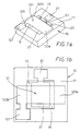
- FIGs. 1a and 1b there is shown a first embodiment of the micro-electro-mechanical pumping stage according to the invention.
- a vibrating planar resilient membrane 121 is suspended above a cavity 13 formed in a supporting base 15.
- Membrane 121 is of substantially rectangular shape and it is fastened to the peripheral rim surrounding cavity 13, formed on supporting base 15, at two rectangular fastening regions 123a, 123b adjacent to the minor sides of membrane 121.
- Said membrane 121 is further provided with a side extension 125 partly overlapping peripheral rim 17 so as to define a corresponding contact area 127.
- Supporting base 15 preferably is a silicon substrate or wafer on which cavity 13 has been formed by conventional etching techniques.
- a metal control electrode 21 is located inside cavity 13, in contact with bottom 19, and is provided with a side extension 23 bent against side wall 25 of cavity 13, which extension partly covers peripheral rim 17 of supporting base 15 and defines a corresponding contact area 27.
- the vibration of membrane 21 will be obtained.
- said signal is sinusoidal with frequencies different from the resonance frequency of membrane 121, membrane 121 will start vibrating at the signal frequency.
- the latter should be made to vibrate at very high speeds, typically of the order of the speed of the gas molecules to be pumped and hence close or equivalent to the membrane resonance speed.
- the voltage applied to the terminals consisting of contact areas 27, 127 in control electrode 21 and vibrating membrane 121, respectively, will be about 100 V.
- Suitable materials for manufacturing membrane 121 may be aluminium, molybdenum, SiO 2 , Si 3 N 4 , Si (single crystalline), the latter being preferable to obtain higher vibration speed of the membrane.
- membranes made of dielectric material such as SiO 2 and Si 3 N 4 , will have a sandwich structure (dielectric - metal - dielectric) where a metal layer is sandwiched between two dielectric layers, so that membrane vibration can be controlled by the electric field.
- membrane 121 may have a surface of 100 ⁇ m x 20 ⁇ m and a thickness of 1 ⁇ m.
- membrane 121 shall have sufficiently broad fastening regions 123a, 123b to prevent the membrane from becoming detached from base 15 while vibrating.
- the fastening regions will preferably have a surface of at least 20 ⁇ m x 20 ⁇ m.
- control electrode 21 will preferably be such that attraction force on membrane 121 is applied to about 50% of the membrane surface, preferably over a length of 25 ⁇ m to 75 ⁇ m in the longitudinal direction of membrane 121 and over the whole width of membrane 121.
- the spacing between membrane 121 and control electrode 21 will preferably be in the range 5 ⁇ m to 15 ⁇ m depending on the material used and on the voltage applied to the contact areas of control electrode 21 and membrane 121.
- a second embodiment of the invention is shown in which the vibrating pumping stage is obtained by means of a planar, substantially H-shaped resilient membrane comprising two parallel longitudinal beams 221a, 221b and a transversal central beam 221c.
- both parallel beams 221a, 221b are fastened at their respective ends 223a, 223b, to peripheral rim 17 of supporting base 15.
- H-shaped membrane 221 is thus suspended above cavity 13 formed in supporting base 15.
- the H-shaped membrane may be imparted a torsional oscillation allowing attaining high resonance frequencies and great amplitudes.
- torsional resonance frequency is much higher than the flexion one.
- an aluminium membrane 150 ⁇ m long, 15 ⁇ m wide and 1,5 ⁇ m thick will have the following resonance frequencies: flexion 3,5e 5 Hz, torsion 2,0e 6 Hz.
- transversal beam 221 c of H-shaped membrane 221 Deflection on the molecules of the surrounding gas caused by transversal beam 221 c of H-shaped membrane 221 will thus be amplified with respect to the case of a single membrane submitted to flexion.
- Central transversal beam 221c should preferably be light and thin in order the resonance frequency of the assembly is not excessively reduced.
- FIG. 3 a third embodiment of the invention is shown in which a multilayer vibrating assembly 321 is provided.
- assembly 321 comprises a substantially rigid membrane 331 supported by substantially S-shaped resilient members or suspension springs 333, located under membrane 331 at respective opposed ends 323a, 323b thereof.
- Resilient members 333 will be in turn fastened to a rectilinear supporting base 15' onto which a control electrode 21' is provided to make assembly 321 vibrate thanks to the application of an electric field between said electrode 21' and membrane 331.
- membrane 331 may advantageously have openings 329 so as to give the membrane a trellis structure conferring sufficient rigidity, so that the membrane is made to oscillate substantially parallel to the plane on which it lies in idle conditions.
- the multilayer configuration of the embodiments shown in Figs. 3 and 4 will advantageously result in the whole surface of membrane 331 being active at the specified speed.
- membrane 331 remains substantially planar during oscillation and, consequently, the whole membrane surface will cause the same deflection on the gas molecules, contrary to what happens with both other configurations previously considered, where, because of the bending, only a limited portion of the membrane has an optimal deflection.
- the multilayer assembly allows attaining a high efficiency in terms of active vibrating surface, since the fastening areas are located below the oscillating surface.
- multilayer assembly 321 may have the following dimensions:
- vibrating pumping sets can be made by coupling a plurality of vibrating pumping stages like those described above.
- Said pumping stages could for instance be arranged in a same plane to form different geometrical configurations with greater or smaller surfaces, for instance disc-shaped configurations, depending on the pumping capacity to be obtained.
- the spacing between the pumping stages could vary depending on the kind of vibrating assembly and could be of the order of a few micrometers, e.g. 3 ⁇ m.
- a molecular vacuum pump including a plurality of micro-electro-mechanical vibrating pumping stages.
- reference numeral 51 denotes a cylindrical casing inside which there are located pumping sets consisting of disc-shaped members 55a, 55b, 55c bearing a plurality of micro-electro-mechanical pumping stages made in accordance with one of the embodiments described with reference to the preceding Figures.
- Said disc-shaped pumping sets 55a, 55b, 55c have a smaller diameter than the internal diameter of cylindrical casing 51 so as to define a corresponding free annulus for letting gas flow between discs 55a - 55c and the internal wall of casing 51.
- Said tubular casing 51 has a first end 53a, which corresponds to the inlet port for the gas to be pumped and which could be connected to a chamber to be evacuated, and a second end 53b, which corresponds to the gas outlet port and which could be connected to the outside environment, preferably through a forepump.
- corresponding vibrating surfaces 57 are defined on said disc-shaped members 55a, 55b, 55c and are obtained by placing side by side a plurality of vibrating pumping stages that move back and forth thereby causing the deflection of the gas molecules inside casing 51 and consequently the gas pumping towards outlet port 53b.
- said pumping devices will be mutually electrically connected on disc-shaped member 55a, 55b, 55c in order to form an integrated unit from which only a pair of conductors for electric power supply comes out.
- the vibration speed of the vibrating surfaces will preferably be of the same order of magnitude as the thermal agitation speed of the molecules of the gas to be pumped through the pump.
- the pumping action on the gas molecules by the vibrating surfaces is substantially given by the direction variation imparted to the molecule paths inside casing 51.
- the vibrating surface moves forth, i.e. towards gas outlet end 53b, it intercepts a greater amount of molecules, and when moving back, i.e. towards the inlet, it intercepts a smaller amount of molecules, with respect to a condition in which the surface is stationary.
- That phenomenon results in an unbalance effect such that the forward projection effect is more accentuated than the backward defocusing effect, and a strong increase is obtained in the probability that the gas molecules are transmitted towards outlet 53b.
- the molecular pump comprises multiple casings 51 housing a number of disc-shaped deflecting members 55 forming respective pumping units.
- each pumping unit 55 could be independently controlled and monitored through a control or "feed-back" device that, by measuring the pump performance, can vary the vibration speed and amplitude of the vibrating surfaces.
- integrated vacuum pumps could be provided inside the ducts for gas flow, thereby obtaining active ducts, which can take different and even non-rectilinear shapes and different lengths depending on the applications.
- the membrane vibration has been obtained by exploiting electrostatic forces to periodically move the membrane closer to an electrode integral with a stationary support. Yet, also electromagnetic fields could be used to move the membrane, such fields allowing creating greater forces.
Landscapes
- Engineering & Computer Science (AREA)
- Mechanical Engineering (AREA)
- General Engineering & Computer Science (AREA)
- Reciprocating Pumps (AREA)
- Micromachines (AREA)
- Apparatuses For Generation Of Mechanical Vibrations (AREA)
Abstract
Description
- The present invention relates to a vibrating pumping stage for vacuum pumps, and to a vacuum pump with vibrating pumping stages.
- More precisely, the invention concerns a micro-electro-mechanical vibrating pumping stage, obtained by means of the technology used for manufacturing MEMS (Micro-Electro-Mechanical Systems).
- The invention further concerns a molecular vacuum pump exploiting vibrating MEMS pumping stages.
- A molecular vacuum pump equipped with vibrating members is known for instance from document WO 00/23715.
- The above patent application teaches manufacturing a molecular vacuum pump by arranging a set of alternated dipoles inside a box communicating on the one side with the chamber to be evacuated and on the other side with the outside environment, through a gas inlet port and a gas outlet port, respectively. Further according to the teaching of said document, the dipoles are obtained by means of piezoelectric elements fastened to respective supports integral with the inner wall of said box.
- Yet, the above patent application does not provide complete indications on the operation of the vibrating elements and on how to obtain in practice the desired pumping effect.
- Some attempts to manufacture vacuum pumps by following the teachings of the above document have given unsatisfactory results. Particularly, the power required for operating a vacuum pump based on the disclosed principles has proven excessive with respect to the attainable results.
- Thus, it is an object of the present invention to provide a micro-electro-mechanical pumping stage for vacuum pumps and a vacuum pump including one or more such stages, which stage and pump allow obtaining industrially applicable results with competitive costs, and obtaining advantages in terms of pumping speed and compression ratio.
- The above and other objects are achieved by the micro-electro-mechanical pumping stage and the vacuum pump as claimed in the appended claims.
- Advantageously, according to the invention, the vibrating micro-electro-mechanical pumping stage is obtained by means of the technology known for developing MEMS (Micro-Electro-Mechanical Systems) devices.
- As known, the term "MEMS" denotes those miniaturised electro-mechanical systems integrating mechanical components, sensors, drivers, and the related electronics, onto a silicon substrate. MEMS components are generally obtained through micro-machining processes that selectively etch silicon, by removing selected parts of the silicon wafer, or that add new structural layers, to form the mechanical and electro-mechanical component.
- Thanks to such technology, it has been possible to produce complete systems, such as micro-drivers, on a chip.
- Advantageously, the technology for manufacturing MEMS exploits manufacturing methods similar to those used for integrated circuits, and thus it can benefit from similar levels of quality, reliability, sophistication and cheapness typical of integrated circuits.
- Hereinafter, some exemplary embodiments of the invention, given by way of non limiting example, will be described with reference to the accompanying drawings, in which:
- Fig. 1a is a top perspective view of a first embodiment of the pumping stage according to the invention;
- Fig. 1b is a top plan view of the pumping stage shown in Fig. 1;
- Fig. 2 is a perspective view of a second embodiment of the pumping stage according to the invention;
- Fig. 3 is a perspective view of a third embodiment of the pumping stage according to the invention;
- Fig. 4 is a front view of a fourth embodiment of the pumping stage according to the invention;
- Fig. 5 is a diagrammatic view of a vacuum pump with vibrating pumping stages according to the invention.
- Referring to Figs. 1a and 1b, there is shown a first embodiment of the micro-electro-mechanical pumping stage according to the invention.
- According to that embodiment, a vibrating planar
resilient membrane 121 is suspended above acavity 13 formed in a supportingbase 15. -
Membrane 121 is of substantially rectangular shape and it is fastened to the peripheralrim surrounding cavity 13, formed on supportingbase 15, at tworectangular fastening regions membrane 121. - Said
membrane 121 is further provided with aside extension 125 partly overlappingperipheral rim 17 so as to define acorresponding contact area 127. - Supporting
base 15 preferably is a silicon substrate or wafer on whichcavity 13 has been formed by conventional etching techniques. - A
metal control electrode 21 is located insidecavity 13, in contact withbottom 19, and is provided with aside extension 23 bent againstside wall 25 ofcavity 13, which extension partly coversperipheral rim 17 of supportingbase 15 and defines acorresponding contact area 27. - By applying a voltage signal to said
areas control electrode 21 andmembrane 121, respectively, an electric field can be produced betweencontrol electrode 21 andmembrane 121, wherebymembrane 121 is attracted towardselectrode 21. - If the voltage signal applied to
contact areas membrane 21 will be obtained. In particular, if said signal is sinusoidal with frequencies different from the resonance frequency ofmembrane 121,membrane 121 will start vibrating at the signal frequency. - To obtain a pumping effect on the gas molecules by the vibrating membrane, the latter should be made to vibrate at very high speeds, typically of the order of the speed of the gas molecules to be pumped and hence close or equivalent to the membrane resonance speed.
- In an exemplary embodiment, the voltage applied to the terminals consisting of
contact areas control electrode 21 and vibratingmembrane 121, respectively, will be about 100 V. - Suitable materials for
manufacturing membrane 121 may be aluminium, molybdenum, SiO2, Si3N4, Si (single crystalline), the latter being preferable to obtain higher vibration speed of the membrane. - Moreover, membranes made of dielectric material, such as SiO2 and Si3N4, will have a sandwich structure (dielectric - metal - dielectric) where a metal layer is sandwiched between two dielectric layers, so that membrane vibration can be controlled by the electric field.
- Generally, short and thick membranes will move at higher speed and short and/or thick membranes will demand higher energy to cause the requested deflection on the molecules of the surrounding gas.
- In an exemplary embodiment of the invention,
membrane 121 may have a surface of 100 µm x 20 µm and a thickness of 1 µm. - Moreover,
membrane 121 shall have sufficientlybroad fastening regions base 15 while vibrating. For instance, in case of membranes of 100 µm x 20 µm x 1 µm, the fastening regions will preferably have a surface of at least 20 µm x 20 µm. - The size of
control electrode 21 will preferably be such that attraction force onmembrane 121 is applied to about 50% of the membrane surface, preferably over a length of 25 µm to 75 µm in the longitudinal direction ofmembrane 121 and over the whole width ofmembrane 121. The spacing betweenmembrane 121 andcontrol electrode 21 will preferably be in the range 5 µm to 15 µm depending on the material used and on the voltage applied to the contact areas ofcontrol electrode 21 andmembrane 121. - Referring to Fig. 2, where elements identical to those shown in Figs. 1a and 1b have been omitted, a second embodiment of the invention is shown in which the vibrating pumping stage is obtained by means of a planar, substantially H-shaped resilient membrane comprising two parallel
longitudinal beams - Similarly to the embodiment shown in Figs. 1a and 1b, both
parallel beams respective ends peripheral rim 17 of supportingbase 15. H-shaped membrane 221 is thus suspended abovecavity 13 formed in supportingbase 15. - Thanks to such a configuration, the H-shaped membrane may be imparted a torsional oscillation allowing attaining high resonance frequencies and great amplitudes.
- Actually, torsional resonance frequency is much higher than the flexion one. For instance, an aluminium membrane 150 µm long, 15 µm wide and 1,5 µm thick will have the following resonance frequencies: flexion 3,5e5 Hz, torsion 2,0e6 Hz.
- Deflection on the molecules of the surrounding gas caused by transversal beam 221 c of H-
shaped membrane 221 will thus be amplified with respect to the case of a single membrane submitted to flexion. Central transversal beam 221c should preferably be light and thin in order the resonance frequency of the assembly is not excessively reduced. - Turning now to Fig. 3, a third embodiment of the invention is shown in which a
multilayer vibrating assembly 321 is provided. - According to this embodiment,
assembly 321 comprises a substantiallyrigid membrane 331 supported by substantially S-shaped resilient members orsuspension springs 333, located undermembrane 331 at respective opposedends -
Resilient members 333 will be in turn fastened to a rectilinear supporting base 15' onto which a control electrode 21' is provided to makeassembly 321 vibrate thanks to the application of an electric field between said electrode 21' andmembrane 331. - Turning to Fig. 4, which shows a fourth embodiment of the invention,
membrane 331 may advantageously haveopenings 329 so as to give the membrane a trellis structure conferring sufficient rigidity, so that the membrane is made to oscillate substantially parallel to the plane on which it lies in idle conditions. - With respect to the case of the simple membrane (Figs. 1a and 1b) or the H-shaped membrane (Fig. 2), the multilayer configuration of the embodiments shown in Figs. 3 and 4 will advantageously result in the whole surface of
membrane 331 being active at the specified speed. - Actually,
membrane 331 remains substantially planar during oscillation and, consequently, the whole membrane surface will cause the same deflection on the gas molecules, contrary to what happens with both other configurations previously considered, where, because of the bending, only a limited portion of the membrane has an optimal deflection. - Advantageously therefore the multilayer assembly allows attaining a high efficiency in terms of active vibrating surface, since the fastening areas are located below the oscillating surface.
- In an exemplary embodiment,
multilayer assembly 321 may have the following dimensions: - membrane thickness: 1 µm;
- vibrating surface length: 15 - 25 µm;
- spring length: 2 - 3 µm;
- assembly thickness: 5 µm;
- spring thickness: 0,5 µm.
- Advantageously, according to the invention, vibrating pumping sets can be made by coupling a plurality of vibrating pumping stages like those described above. Said pumping stages could for instance be arranged in a same plane to form different geometrical configurations with greater or smaller surfaces, for instance disc-shaped configurations, depending on the pumping capacity to be obtained. The spacing between the pumping stages could vary depending on the kind of vibrating assembly and could be of the order of a few micrometers, e.g. 3 µm.
- Referring to Fig. 5, there is schematically shown a molecular vacuum pump including a plurality of micro-electro-mechanical vibrating pumping stages.
- In Fig. 5,
reference numeral 51 denotes a cylindrical casing inside which there are located pumping sets consisting of disc-shapedmembers - Said disc-shaped pumping sets 55a, 55b, 55c have a smaller diameter than the internal diameter of
cylindrical casing 51 so as to define a corresponding free annulus for letting gas flow betweendiscs 55a - 55c and the internal wall ofcasing 51. - Said
tubular casing 51 has afirst end 53a, which corresponds to the inlet port for the gas to be pumped and which could be connected to a chamber to be evacuated, and asecond end 53b, which corresponds to the gas outlet port and which could be connected to the outside environment, preferably through a forepump. - According to the invention, corresponding vibrating
surfaces 57 are defined on said disc-shapedmembers casing 51 and consequently the gas pumping towardsoutlet port 53b. - Advantageously moreover said pumping devices will be mutually electrically connected on disc-shaped
member - For an optimum operation of the vacuum pump thus obtained, the vibration speed of the vibrating surfaces will preferably be of the same order of magnitude as the thermal agitation speed of the molecules of the gas to be pumped through the pump.
- The pumping action on the gas molecules by the vibrating surfaces is substantially given by the direction variation imparted to the molecule paths inside
casing 51. - When the vibrating surface moves forth, i.e. towards
gas outlet end 53b, it intercepts a greater amount of molecules, and when moving back, i.e. towards the inlet, it intercepts a smaller amount of molecules, with respect to a condition in which the surface is stationary. - That phenomenon results in an unbalance effect such that the forward projection effect is more accentuated than the backward defocusing effect, and a strong increase is obtained in the probability that the gas molecules are transmitted towards
outlet 53b. - In a preferred embodiment, the molecular pump comprises
multiple casings 51 housing a number of disc-shaped deflecting members 55 forming respective pumping units. - Moreover, each pumping unit 55 could be independently controlled and monitored through a control or "feed-back" device that, by measuring the pump performance, can vary the vibration speed and amplitude of the vibrating surfaces.
- Advantageously, according to the proposed arrangement, integrated vacuum pumps could be provided inside the ducts for gas flow, thereby obtaining active ducts, which can take different and even non-rectilinear shapes and different lengths depending on the applications.
- In the disclosed examples, the membrane vibration has been obtained by exploiting electrostatic forces to periodically move the membrane closer to an electrode integral with a stationary support. Yet, also electromagnetic fields could be used to move the membrane, such fields allowing creating greater forces.
- Of course, different structures, geometries and material could be used to manufacture the membrane, the choice of the best configuration being determined by the kind of gas, the pumping rate and the compression ratio to be obtained.
Claims (30)
- A vibrating pumping stage for vacuum pumps, comprising:a supporting base (15; 15');a vibrating assembly (121; 221; 321) fastened to said supporting base (15; 15'), said vibrating assembly comprising an active surface by which the deflection of the molecules of surrounding gas is caused during vibration of said vibrating assembly:a control device (21) placed onto said supporting base (15; 15') to make said vibrating assembly vibrate and consequently cause deflection of said gas molecules.
- A pumping stage as claimed in claim 1, wherein said pumping stage is a micro-electro-mechanical system (MEMS).
- A pumping stage as claimed in claim 1 or 2, wherein said supporting base (15; 15') comprises a silicon wafer.
- A pumping stage as claimed in claim 3, wherein said control device (21) is placed between said supporting base (15; 15') and said vibrating assembly (121; 221; 321).
- A pumping stage as claimed in claim 4, wherein said control device (21) is an electrode and wherein a variable electric field is produced between said electrode and said vibrating assembly to cause vibration of said vibrating assembly with respect to said supporting base.
- A pumping stage as claimed in claim 5, wherein said electric field is generated by a sinusoidal signal.
- A pumping stage as claimed in claim 6, wherein said sinusoidal signal has a frequency close to the resonance frequency of said vibrating assembly.
- A pumping stage as claimed in claim 5, wherein a cavity (13) housing said electrode is formed in said supporting base below said vibrating assembly.
- A pumping stage as claimed in claim 8, wherein said vibrating assembly is a planar resilient membrane.
- A pumping stage as claimed in claim 9, wherein said membrane is substantially rectangular and is fastened to said supporting base at its ends (123a, 123b) corresponding to the minor sides of said rectangle.
- A pumping stage as claimed in claim 9, wherein said membrane is substantially H-shaped and is fastened to said supporting base at its four ends (223a, 223b).
- A pumping stage as claimed in claim 11, wherein said H-shaped membrane is submitted to a torsional vibration.
- A pumping stage as claimed in claim 10 or 11, wherein said membrane is fastened to said supporting base along the peripheral rim (17) surrounding said cavity (13), whereby said membrane is suspended above said cavity.
- A pumping stage as claimed in claim 13, wherein said membrane comprises a side extension (125) partly overlapping said peripheral rim so as to define a corresponding first contact area (127).
- A pumping stage as claimed in claim 13, wherein said electrode comprises a side extension (23) such that the electrode partly overlaps the peripheral rim (17) of said supporting base (15) so as to define a corresponding second contact area (27).
- A pumping stage as claimed in claim 15, wherein said sinusoidal signal is applied to said contact areas to generate a variable electric field between said vibrating assembly and said control device, said electric field causing vibration of said assembly.
- A pumping stage as claimed in claim 5, wherein said vibrating assembly comprises a rigid membrane (331) supported by resilient members or suspension springs (333), placed between said membrane (331) and said supporting base, said resilient members being fastened to said supporting base.
- A pumping stage as claimed in claim 17, wherein said membrane and said supporting base have a substantially parallepipedal rectilinear shape.
- A pumping stage as claimed in claim 18, wherein said resilient members are S-shaped.
- A pumping stage as claimed in claim 18, wherein said membrane is provided with openings (329) so as to give the membrane a sufficiently rigid trellis structure making the membrane vibrate substantially parallel to the plane on which it lies in idle conditions.
- A pumping stage as claimed in any of claims 9 to 20, wherein the spacing between said membrane and said electrode is in the range of about 5 µm to 15 µm.
- A pumping stage as claimed in any of claims 9 to 21, wherein the attraction force exerted by said electrode on said membrane because of said electric field is applied to about 50% of the surface of said membrane.
- A pumping stage as claimed in claim 9, wherein said rectangular membrane has a surface of 100 x 20 µm and a thickness of 1 µm.
- A pumping stage as claimed in claim 11, wherein said H-shaped membrane is 150 µm long, 15 µm wide and 1, 5 µm thick.
- A pumping stage as claimed in any of claims 9 to 24, wherein said membrane is made of a material chosen out of aluminium, molybdenum, SiO2, Si3N4, Si (single crystalline).
- A vacuum pump comprising at least one vibrating pumping stage obtained according to any preceding claim.
- A vacuum pump as claimed in claim 26, comprising a cylindrical casing (51) having a gas inlet port (53a) and an outlet port (53b), said casing housing at least one disc-shaped vibrating pumping set.
- A vacuum pump as claimed in claim 27, wherein said disc-shaped pumping set comprises a plurality of vibrating pumping stages.
- A vacuum pump as claimed in claim 28, wherein said pumping set (55) is arranged perpendicular to the axis of the cylindrical casing (51), and wherein a free annulus is provided between said disc and said casing for gas passage.
- A vacuum pump as claimed in claim 29, wherein said casing is a non-rectilinear duct for gas flow.
Applications Claiming Priority (2)
| Application Number | Priority Date | Filing Date | Title |
|---|---|---|---|
| ITTO20020859 | 2002-10-04 | ||
| IT000859A ITTO20020859A1 (en) | 2002-10-04 | 2002-10-04 | VIBRATING PUMPING STAGE FOR VACUUM PUMPS AND VIBRATING PUMP VACUUM PUMPS. |
Publications (3)
| Publication Number | Publication Date |
|---|---|
| EP1406020A2 true EP1406020A2 (en) | 2004-04-07 |
| EP1406020A3 EP1406020A3 (en) | 2005-01-12 |
| EP1406020B1 EP1406020B1 (en) | 2012-10-31 |
Family
ID=31986062
Family Applications (1)
| Application Number | Title | Priority Date | Filing Date |
|---|---|---|---|
| EP03021648A Expired - Lifetime EP1406020B1 (en) | 2002-10-04 | 2003-09-26 | Vibrating pumping stage for vacuum pumps, and vacuum pump with vibrating pumping stages |
Country Status (5)
| Country | Link |
|---|---|
| US (1) | US7083398B2 (en) |
| EP (1) | EP1406020B1 (en) |
| JP (1) | JP2004263689A (en) |
| DE (1) | DE03021648T1 (en) |
| IT (1) | ITTO20020859A1 (en) |
Cited By (6)
| Publication number | Priority date | Publication date | Assignee | Title |
|---|---|---|---|---|
| US9642955B2 (en) | 2006-09-28 | 2017-05-09 | Smith & Nephew, Inc. | Portable wound therapy system |
| US10143783B2 (en) | 2011-11-02 | 2018-12-04 | Smith & Nephew Plc | Reduced pressure therapy apparatuses and methods of using same |
| US10299964B2 (en) | 2012-05-15 | 2019-05-28 | Smith & Nephew Plc | Negative pressure wound therapy apparatus |
| US10682446B2 (en) | 2014-12-22 | 2020-06-16 | Smith & Nephew Plc | Dressing status detection for negative pressure wound therapy |
| US11027051B2 (en) | 2010-09-20 | 2021-06-08 | Smith & Nephew Plc | Pressure control apparatus |
| US12029549B2 (en) | 2007-12-06 | 2024-07-09 | Smith & Nephew Plc | Apparatus and method for wound volume measurement |
Families Citing this family (4)
| Publication number | Priority date | Publication date | Assignee | Title |
|---|---|---|---|---|
| US7090471B2 (en) * | 2003-01-15 | 2006-08-15 | California Institute Of Technology | Integrated electrostatic peristaltic pump method and apparatus |
| US20060073035A1 (en) * | 2004-09-30 | 2006-04-06 | Narayan Sundararajan | Deformable polymer membranes |
| EP1722412B1 (en) * | 2005-05-02 | 2012-08-29 | Sony Corporation | Jet generator and electronic device |
| US10670001B2 (en) * | 2008-02-21 | 2020-06-02 | Clean Energy Labs, Llc | Energy conversion system including a ballistic rectifier assembly and uses thereof |
Citations (3)
| Publication number | Priority date | Publication date | Assignee | Title |
|---|---|---|---|---|
| GB2210414A (en) | 1987-10-01 | 1989-06-07 | Emi Plc Thorn | A pumping device |
| WO2000007735A2 (en) | 1998-08-05 | 2000-02-17 | The Regents Of The University Of Michigan | Micromachined acoustic ejectors and applications |
| WO2002021568A2 (en) | 2000-09-01 | 2002-03-14 | Mcnc | Distributed mems electrostatic pumping devices |
Family Cites Families (11)
| Publication number | Priority date | Publication date | Assignee | Title |
|---|---|---|---|---|
| US862867A (en) * | 1906-03-28 | 1907-08-06 | Lewis Watson Eggleston | Pneumatic pumping apparatus. |
| DE3925749C1 (en) * | 1989-08-03 | 1990-10-31 | Fraunhofer-Gesellschaft Zur Foerderung Der Angewandten Forschung Ev, 8000 Muenchen, De | |
| US6010316A (en) * | 1996-01-16 | 2000-01-04 | The Board Of Trustees Of The Leland Stanford Junior University | Acoustic micropump |
| JP2001502247A (en) * | 1996-02-10 | 2001-02-20 | フラウンホーファー―ゲゼルシャフト、ツール、フェルデルング、デァ、アンゲヴァンテン、フォルシュング、アインゲトラーゲネル、フェライン | Bistable microactuator with membrane connection |
| US6069392A (en) * | 1997-04-11 | 2000-05-30 | California Institute Of Technology | Microbellows actuator |
| US6116863A (en) * | 1997-05-30 | 2000-09-12 | University Of Cincinnati | Electromagnetically driven microactuated device and method of making the same |
| US5836750A (en) * | 1997-10-09 | 1998-11-17 | Honeywell Inc. | Electrostatically actuated mesopump having a plurality of elementary cells |
| US6351054B1 (en) * | 1997-10-09 | 2002-02-26 | Honeywell International Inc. | Compounded AC driving signal for increased reliability and lifetime in touch-mode electrostatic actuators |
| US6247908B1 (en) * | 1998-03-05 | 2001-06-19 | Seiko Instruments Inc. | Micropump |
| EP0995908A1 (en) * | 1998-10-20 | 2000-04-26 | vanden Brande, Pierre | Molecular pump |
| US6210128B1 (en) * | 1999-04-16 | 2001-04-03 | The United States Of America As Represented By The Secretary Of The Navy | Fluidic drive for miniature acoustic fluidic pumps and mixers |
-
2002
- 2002-10-04 IT IT000859A patent/ITTO20020859A1/en unknown
-
2003
- 2003-09-10 US US10/659,627 patent/US7083398B2/en not_active Expired - Fee Related
- 2003-09-17 JP JP2003324836A patent/JP2004263689A/en active Pending
- 2003-09-26 EP EP03021648A patent/EP1406020B1/en not_active Expired - Lifetime
- 2003-09-26 DE DE0001406020T patent/DE03021648T1/en active Pending
Patent Citations (3)
| Publication number | Priority date | Publication date | Assignee | Title |
|---|---|---|---|---|
| GB2210414A (en) | 1987-10-01 | 1989-06-07 | Emi Plc Thorn | A pumping device |
| WO2000007735A2 (en) | 1998-08-05 | 2000-02-17 | The Regents Of The University Of Michigan | Micromachined acoustic ejectors and applications |
| WO2002021568A2 (en) | 2000-09-01 | 2002-03-14 | Mcnc | Distributed mems electrostatic pumping devices |
Cited By (21)
| Publication number | Priority date | Publication date | Assignee | Title |
|---|---|---|---|---|
| US9642955B2 (en) | 2006-09-28 | 2017-05-09 | Smith & Nephew, Inc. | Portable wound therapy system |
| US10130526B2 (en) | 2006-09-28 | 2018-11-20 | Smith & Nephew, Inc. | Portable wound therapy system |
| US11141325B2 (en) | 2006-09-28 | 2021-10-12 | Smith & Nephew, Inc. | Portable wound therapy system |
| US12115302B2 (en) | 2006-09-28 | 2024-10-15 | Smith & Nephew, Inc. | Portable wound therapy system |
| US12029549B2 (en) | 2007-12-06 | 2024-07-09 | Smith & Nephew Plc | Apparatus and method for wound volume measurement |
| US11027051B2 (en) | 2010-09-20 | 2021-06-08 | Smith & Nephew Plc | Pressure control apparatus |
| US12226611B2 (en) | 2010-09-20 | 2025-02-18 | Smith & Nephew Plc | Pressure control apparatus |
| US11623039B2 (en) | 2010-09-20 | 2023-04-11 | Smith & Nephew Plc | Systems and methods for controlling operation of a reduced pressure therapy system |
| US11534540B2 (en) | 2010-09-20 | 2022-12-27 | Smith & Nephew Plc | Pressure control apparatus |
| US12582762B2 (en) | 2011-11-02 | 2026-03-24 | Smith & Nephew Plc | Reduced pressure therapy apparatuses and methods of using same |
| US11648342B2 (en) | 2011-11-02 | 2023-05-16 | Smith & Nephew Plc | Reduced pressure therapy apparatuses and methods of using same |
| US10143783B2 (en) | 2011-11-02 | 2018-12-04 | Smith & Nephew Plc | Reduced pressure therapy apparatuses and methods of using same |
| US11253639B2 (en) | 2011-11-02 | 2022-02-22 | Smith & Nephew Plc | Reduced pressure therapy apparatuses and methods of using same |
| US10702418B2 (en) | 2012-05-15 | 2020-07-07 | Smith & Nephew Plc | Negative pressure wound therapy apparatus |
| US12116991B2 (en) | 2012-05-15 | 2024-10-15 | Smith & Nephew Plc | Negative pressure wound therapy apparatus |
| US10299964B2 (en) | 2012-05-15 | 2019-05-28 | Smith & Nephew Plc | Negative pressure wound therapy apparatus |
| US10973965B2 (en) | 2014-12-22 | 2021-04-13 | Smith & Nephew Plc | Systems and methods of calibrating operating parameters of negative pressure wound therapy apparatuses |
| US11654228B2 (en) | 2014-12-22 | 2023-05-23 | Smith & Nephew Plc | Status indication for negative pressure wound therapy |
| US10780202B2 (en) | 2014-12-22 | 2020-09-22 | Smith & Nephew Plc | Noise reduction for negative pressure wound therapy apparatuses |
| US10737002B2 (en) | 2014-12-22 | 2020-08-11 | Smith & Nephew Plc | Pressure sampling systems and methods for negative pressure wound therapy |
| US10682446B2 (en) | 2014-12-22 | 2020-06-16 | Smith & Nephew Plc | Dressing status detection for negative pressure wound therapy |
Also Published As
| Publication number | Publication date |
|---|---|
| DE03021648T1 (en) | 2004-08-26 |
| JP2004263689A (en) | 2004-09-24 |
| EP1406020B1 (en) | 2012-10-31 |
| EP1406020A3 (en) | 2005-01-12 |
| ITTO20020859A1 (en) | 2004-04-05 |
| US7083398B2 (en) | 2006-08-01 |
| US20040101422A1 (en) | 2004-05-27 |
Similar Documents
| Publication | Publication Date | Title |
|---|---|---|
| KR102033228B1 (en) | Mems having micromechanical piezoelectric actuators for realizing high forces and deflections | |
| KR102816960B1 (en) | MEMS transducers with improved performance | |
| CN108966101B (en) | Single diaphragm transducer structure | |
| TWI848234B (en) | Mems device | |
| US7083398B2 (en) | Vibrating pumping stage for molecular vacuum pumps, and molecular vacuum pump with vibrating pumping stages | |
| JP6756991B2 (en) | Piezoelectric MEMS resonator with high Q value | |
| US7161275B2 (en) | Actuator | |
| US20110025169A1 (en) | Piezoelectric drive unit | |
| JP4435695B2 (en) | Piezoelectric motor operation method and piezoelectric motor in the form of a hollow cylindrical oscillator having a stator | |
| JPH1047966A (en) | Angular velocity sensor | |
| EP1530036B1 (en) | Pressure sensor | |
| KR101000642B1 (en) | Natural frequency tuning device of micro resonator by mechanical restraint of MEMS driver, micro resonator having same, manufacturing method and tuning method thereof | |
| WO2019240007A1 (en) | Electrostatic actuator and physical quantity sensor | |
| JP2001264676A (en) | Optical scanner | |
| JP2004353638A (en) | Micro pump | |
| JP4965962B2 (en) | Micromechanical resonator | |
| JPH06277624A (en) | Small-sized actuator | |
| KR100425530B1 (en) | Actuator for generating flow from a surface of an object in multi-direction | |
| JP3230331B2 (en) | Angular velocity sensor | |
| JP4254362B2 (en) | Micro pump | |
| JP2026060443A (en) | MEMS transducer | |
| JPS6255500A (en) | Piezo-electric fan | |
| CN117833854A (en) | MEMS Resonators | |
| JP2009118281A (en) | Micro mechanical resonator | |
| JP2008145385A (en) | Inertial sensor, manufacturing method thereof, and structure substrate |
Legal Events
| Date | Code | Title | Description |
|---|---|---|---|
| PUAI | Public reference made under article 153(3) epc to a published international application that has entered the european phase |
Free format text: ORIGINAL CODE: 0009012 |
|
| AK | Designated contracting states |
Kind code of ref document: A2 Designated state(s): AT BE BG CH CY CZ DE DK EE ES FI FR GB GR HU IE IT LI LU MC NL PT RO SE SI SK TR |
|
| AX | Request for extension of the european patent |
Extension state: AL LT LV MK |
|
| EL | Fr: translation of claims filed | ||
| DET | De: translation of patent claims | ||
| PUAL | Search report despatched |
Free format text: ORIGINAL CODE: 0009013 |
|
| AK | Designated contracting states |
Kind code of ref document: A3 Designated state(s): AT BE BG CH CY CZ DE DK EE ES FI FR GB GR HU IE IT LI LU MC NL PT RO SE SI SK TR |
|
| AX | Request for extension of the european patent |
Extension state: AL LT LV MK |
|
| 17P | Request for examination filed |
Effective date: 20050331 |
|
| AKX | Designation fees paid |
Designated state(s): DE FR GB IT |
|
| RAP1 | Party data changed (applicant data changed or rights of an application transferred) |
Owner name: AGILENT TECHNOLOGIES ITALIA S.P.A. |
|
| RAP1 | Party data changed (applicant data changed or rights of an application transferred) |
Owner name: AGILENT TECHNOLOGIES ITALIA S.P.A. |
|
| GRAP | Despatch of communication of intention to grant a patent |
Free format text: ORIGINAL CODE: EPIDOSNIGR1 |
|
| RAP1 | Party data changed (applicant data changed or rights of an application transferred) |
Owner name: AGILENT TECHNOLOGIES, INC. |
|
| GRAS | Grant fee paid |
Free format text: ORIGINAL CODE: EPIDOSNIGR3 |
|
| GRAA | (expected) grant |
Free format text: ORIGINAL CODE: 0009210 |
|
| AK | Designated contracting states |
Kind code of ref document: B1 Designated state(s): DE FR GB IT |
|
| REG | Reference to a national code |
Ref country code: GB Ref legal event code: FG4D |
|
| REG | Reference to a national code |
Ref country code: DE Ref legal event code: R096 Ref document number: 60342468 Country of ref document: DE Effective date: 20121227 |
|
| PG25 | Lapsed in a contracting state [announced via postgrant information from national office to epo] |
Ref country code: IT Free format text: LAPSE BECAUSE OF FAILURE TO SUBMIT A TRANSLATION OF THE DESCRIPTION OR TO PAY THE FEE WITHIN THE PRESCRIBED TIME-LIMIT Effective date: 20121031 |
|
| PLBE | No opposition filed within time limit |
Free format text: ORIGINAL CODE: 0009261 |
|
| STAA | Information on the status of an ep patent application or granted ep patent |
Free format text: STATUS: NO OPPOSITION FILED WITHIN TIME LIMIT |
|
| 26N | No opposition filed |
Effective date: 20130801 |
|
| REG | Reference to a national code |
Ref country code: DE Ref legal event code: R097 Ref document number: 60342468 Country of ref document: DE Effective date: 20130801 |
|
| GBPC | Gb: european patent ceased through non-payment of renewal fee |
Effective date: 20130926 |
|
| REG | Reference to a national code |
Ref country code: DE Ref legal event code: R119 Ref document number: 60342468 Country of ref document: DE Effective date: 20140401 |
|
| REG | Reference to a national code |
Ref country code: FR Ref legal event code: ST Effective date: 20140530 |
|
| PG25 | Lapsed in a contracting state [announced via postgrant information from national office to epo] |
Ref country code: GB Free format text: LAPSE BECAUSE OF NON-PAYMENT OF DUE FEES Effective date: 20130926 |
|
| PG25 | Lapsed in a contracting state [announced via postgrant information from national office to epo] |
Ref country code: FR Free format text: LAPSE BECAUSE OF NON-PAYMENT OF DUE FEES Effective date: 20130930 Ref country code: DE Free format text: LAPSE BECAUSE OF NON-PAYMENT OF DUE FEES Effective date: 20140401 |