EP1405996A1 - Operating method for a rotary engine and a rotary internal combustion engine - Google Patents
Operating method for a rotary engine and a rotary internal combustion engine Download PDFInfo
- Publication number
- EP1405996A1 EP1405996A1 EP02774088A EP02774088A EP1405996A1 EP 1405996 A1 EP1405996 A1 EP 1405996A1 EP 02774088 A EP02774088 A EP 02774088A EP 02774088 A EP02774088 A EP 02774088A EP 1405996 A1 EP1405996 A1 EP 1405996A1
- Authority
- EP
- European Patent Office
- Prior art keywords
- chamber
- working
- compression
- engine
- combustion
- Prior art date
- Legal status (The legal status is an assumption and is not a legal conclusion. Google has not performed a legal analysis and makes no representation as to the accuracy of the status listed.)
- Withdrawn
Links
- 238000002485 combustion reaction Methods 0.000 title claims abstract description 34
- 238000011017 operating method Methods 0.000 title 1
- 230000006835 compression Effects 0.000 claims abstract description 42
- 238000007906 compression Methods 0.000 claims abstract description 42
- 239000000203 mixture Substances 0.000 claims abstract description 14
- 239000000463 material Substances 0.000 claims abstract description 11
- 238000000034 method Methods 0.000 claims abstract description 6
- 239000000446 fuel Substances 0.000 abstract description 6
- 238000004519 manufacturing process Methods 0.000 abstract description 3
- 230000003247 decreasing effect Effects 0.000 abstract description 2
- 230000005540 biological transmission Effects 0.000 description 2
- 230000004888 barrier function Effects 0.000 description 1
- 238000001816 cooling Methods 0.000 description 1
- 238000009826 distribution Methods 0.000 description 1
- 238000002347 injection Methods 0.000 description 1
- 239000007924 injection Substances 0.000 description 1
- 230000001050 lubricating effect Effects 0.000 description 1
- 238000003825 pressing Methods 0.000 description 1
- 239000000243 solution Substances 0.000 description 1
Images


Classifications
-
- F—MECHANICAL ENGINEERING; LIGHTING; HEATING; WEAPONS; BLASTING
- F01—MACHINES OR ENGINES IN GENERAL; ENGINE PLANTS IN GENERAL; STEAM ENGINES
- F01C—ROTARY-PISTON OR OSCILLATING-PISTON MACHINES OR ENGINES
- F01C1/00—Rotary-piston machines or engines
- F01C1/24—Rotary-piston machines or engines of counter-engagement type, i.e. the movement of co-operating members at the points of engagement being in opposite directions
- F01C1/28—Rotary-piston machines or engines of counter-engagement type, i.e. the movement of co-operating members at the points of engagement being in opposite directions of other than internal-axis type
-
- F—MECHANICAL ENGINEERING; LIGHTING; HEATING; WEAPONS; BLASTING
- F02—COMBUSTION ENGINES; HOT-GAS OR COMBUSTION-PRODUCT ENGINE PLANTS
- F02B—INTERNAL-COMBUSTION PISTON ENGINES; COMBUSTION ENGINES IN GENERAL
- F02B53/00—Internal-combustion aspects of rotary-piston or oscillating-piston engines
- F02B53/02—Methods of operating
-
- F—MECHANICAL ENGINEERING; LIGHTING; HEATING; WEAPONS; BLASTING
- F02—COMBUSTION ENGINES; HOT-GAS OR COMBUSTION-PRODUCT ENGINE PLANTS
- F02B—INTERNAL-COMBUSTION PISTON ENGINES; COMBUSTION ENGINES IN GENERAL
- F02B55/00—Internal-combustion aspects of rotary pistons; Outer members for co-operation with rotary pistons
- F02B55/14—Shapes or constructions of combustion chambers
-
- F—MECHANICAL ENGINEERING; LIGHTING; HEATING; WEAPONS; BLASTING
- F02—COMBUSTION ENGINES; HOT-GAS OR COMBUSTION-PRODUCT ENGINE PLANTS
- F02B—INTERNAL-COMBUSTION PISTON ENGINES; COMBUSTION ENGINES IN GENERAL
- F02B53/00—Internal-combustion aspects of rotary-piston or oscillating-piston engines
-
- Y—GENERAL TAGGING OF NEW TECHNOLOGICAL DEVELOPMENTS; GENERAL TAGGING OF CROSS-SECTIONAL TECHNOLOGIES SPANNING OVER SEVERAL SECTIONS OF THE IPC; TECHNICAL SUBJECTS COVERED BY FORMER USPC CROSS-REFERENCE ART COLLECTIONS [XRACs] AND DIGESTS
- Y02—TECHNOLOGIES OR APPLICATIONS FOR MITIGATION OR ADAPTATION AGAINST CLIMATE CHANGE
- Y02T—CLIMATE CHANGE MITIGATION TECHNOLOGIES RELATED TO TRANSPORTATION
- Y02T10/00—Road transport of goods or passengers
- Y02T10/10—Internal combustion engine [ICE] based vehicles
- Y02T10/12—Improving ICE efficiencies
Definitions
- the invention relates to propulsion engineering and particularly to methods of operation of rotary internal-combustion engines an d their structures.
- US Patent 3,951,111, F02B 53/08, 1976 discloses a method of operation of a rotary internal-combustion engine comprised of two rotors provided with two sliding blades forming together with flanges of slide valves a chargin g tank and an engine chamber, characterised in that its operation is based on a four -stroke cycle in which a compressed and ready for ignition combustible mixture is cross -injected between the charging tank of the first cylinder and the engine chamber of t he second cylinder after a compression stroke.
- a disadvantage of such engine is that injection of compressed combustible mixture from the charging tank to the engine chamber lowers efficiency of the compression stroke. Additionally, inability to set advan ce ignition at higher rotation results in fuel inefficiency and poor ecological compatibility. This also lowers rotation frequency of an engine working shaft.
- the closest prior art for the present invention is constituted by a rotary internal - combustion engine which comprises two cylinders sharing the same axis and including two off-centre rotors with four radial sliding blades each of which has two slots accommodating the ends of stay -spring rods (US Patent No. 3,858,550, class F02B 53/08, 1975).
- This solution is disadvantageous in that unilateral dislocation of a rotor from an axis causes enhanced vibration in an engine due to sliding rotor blades. Furthermore, inability to set advance ignition at higher rotation results in fuel inefficiency and lowering ecological compatibility. This also lowers rotation frequency of the working shaft in an engine.
- the problems solved by the present invention are improving fuel efficiency and ecological compatibility of an engine, providi ng it with the ability to set advance ignition, increasing the rotation frequency of a working shaft and decreasing its vibration, as well as making the manufacturing of such engine more cost effective.
- the said problem is solved due to a method of operat ion of a rotary internal-combustion engine which includes feeding components of combustible mixture in a compression chamber and a working chamber, their compression and ejection to the compression chamber, ignition and combustion of combustible mixture yi elding combustion materials further directed in the working chamber, rotation of a rotor connected to a working shaft by combustion materials which are afterwards discharged from the working chamber, in which the compression chamber is moved outside the wo rking chamber and in relation to this chamber from the moment when compression of the combustible mixture ends through the discharge of combustion materials into the working chamber.
- a rotary internal-combustion engine comprised of a housing closed with lids and provided with intake and exhaust ports, wherein rotors are mounted in the housing and are gasketed against the walls of the housing, its lids and between each other, thus forming with them operational and compression chambers, the rotors being mounted to move the compression chamber outside the working chamber and in relation to this chamber, the working chamber having a screen separating the intake port from the exhaust port.
- the rotary internal-combustion engine may have several combustion chambers for one working chamber, as well as several working chambers for one combustion chamber.
- the compression chambers may be made connectable with each other.
- the working chambers may be also formed connectable with each other.
- the rotary internal-combustion engine comprises a housing 1 where rotors 2 and 3 are mounted in its chambers.
- the housing is provided with an intake port 4 and an exhaust port 5.
- the housing of the engine is also closed with lids 6 on which bearings 7 of the rotors are mounted co -axially with the chambers of the housing.
- the rotor 3 is connected with the working shaft 8 of the engine.
- the rotors comprise spring-loaded blades 9 and are connected with each other through the transmission 10 (for example, gear-type transmission) providing interrelated rotation of the rotors.
- the blades 9 may be equipped with the counter -loads 11 (Fig. 3) in order to reduce their pressing toward the housing of the engine by centrifugal forces during the operation of the engine.
- the compression chamber 12 holds a fuel injector or igniter plug 13.
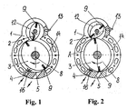
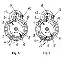
- the screen may be made as a spring -loaded plate 15 (Fig. 7), as a gaseous (air) barrier 16 (Fig. 1, 2, 4, 5, 6 in engines with pressurisation) or as an additional rotor 17 (Fig. 8).
- the spring-loaded blades 9 serve as gaskets between the rotors, housing and lids of the engine. These blades can not perform reciprocal movement in slots of rotors rotating within cylindrical chambers of engine housing (Fig. 1, 2, 4, 5, 7, 8). However, the blades 9 can move reciprocally in slots of the rotors when the latter rotate in non - cylindrical chambers of the housing (Fig.
- the structures of the engine according to the invention may be provided with one (Fig. 1, 2, 6, 7, 8) and several compression chambers (Fig. 4, 5) for one working chamber.
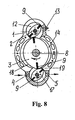
- the engine (Fig. 8) may also have an additional compression chamber 18 (formed by the additional rotor 17) and a working chamber 19, with the compression chamber 18 being connectable to the compression chamber 12, and the working chamber 19 being connectable to the working chamber 14.
- Such design of the engine (Fig. 8) allows an increase in the degree of compression and in fuel-efficiency.
- the engine is also provided with a fuel system, ignition system, lubricating system, cooling system and gaseous distribution system.
- the rotors 2 and 3 start rotating thus forming and moving the compression chamber 12 and the working chamber 14.
- Components of combustible mixture are injected in chamber A (with its volume being increased, Fig. 2) through the intake port 4 and further compressed to the volume of the compression chamber 12.
- the chamber 12 moves outside the working chamber 14 and in relation to this chamber, and ignition takes place in this chamber (in advance, if necessary), and the combustible mixture combusts yielding combustion materials which are further directed in the working chamber 14 and which rotate the rotor 3 connected to the working shaft 8.
- components of combustible mixture are first injected and compressed in the compression chamber 18 and are then ejected to the compression chamber 12. Combustion materials are directed from the working chamber 14 to the working chamber 19, where they rotate the rotor 3 with the working shaft 8 of the engine, with their subsequent discharge combustion from the engine through the exhaust port 5.
- the use of the present invention allows to make the engine more cost -effective and ecologically compatible, increase rotation frequency of the working shaft of this engine due to providing advance ignition, which does not cause negative torque in the engine, and to reduce vibration of the engine due to placing its rotors co -axially with chambers in the housing wh ere they are mounted, as well as to make the manufacture of such an engine more cost-effective due to the simplicity of its design.
Landscapes
- Engineering & Computer Science (AREA)
- Mechanical Engineering (AREA)
- General Engineering & Computer Science (AREA)
- Chemical & Material Sciences (AREA)
- Combustion & Propulsion (AREA)
- Physics & Mathematics (AREA)
- Geometry (AREA)
- Output Control And Ontrol Of Special Type Engine (AREA)
- Combustion Methods Of Internal-Combustion Engines (AREA)
- Supercharger (AREA)
- Ignition Installations For Internal Combustion Engines (AREA)
Abstract
Description
- The invention relates to propulsion engineering and particularly to methods of operation of rotary internal-combustion engines an d their structures.
- US Patent 3,951,111, F02B 53/08, 1976 discloses a method of operation of a rotary internal-combustion engine comprised of two rotors provided with two sliding blades forming together with flanges of slide valves a chargin g tank and an engine chamber, characterised in that its operation is based on a four -stroke cycle in which a compressed and ready for ignition combustible mixture is cross -injected between the charging tank of the first cylinder and the engine chamber of t he second cylinder after a compression stroke.
- A disadvantage of such engine is that injection of compressed combustible mixture from the charging tank to the engine chamber lowers efficiency of the compression stroke. Additionally, inability to set advan ce ignition at higher rotation results in fuel inefficiency and poor ecological compatibility. This also lowers rotation frequency of an engine working shaft.
- The closest prior art for the present invention is constituted by a rotary internal - combustion engine which comprises two cylinders sharing the same axis and including two off-centre rotors with four radial sliding blades each of which has two slots accommodating the ends of stay -spring rods (US Patent No. 3,858,550, class F02B 53/08, 1975).
- This solution is disadvantageous in that unilateral dislocation of a rotor from an axis causes enhanced vibration in an engine due to sliding rotor blades. Furthermore, inability to set advance ignition at higher rotation results in fuel inefficiency and lowering ecological compatibility. This also lowers rotation frequency of the working shaft in an engine.
- The problems solved by the present invention are improving fuel efficiency and ecological compatibility of an engine, providi ng it with the ability to set advance ignition, increasing the rotation frequency of a working shaft and decreasing its vibration, as well as making the manufacturing of such engine more cost effective.
- The said problem is solved due to a method of operat ion of a rotary internal-combustion engine which includes feeding components of combustible mixture in a compression chamber and a working chamber, their compression and ejection to the compression chamber, ignition and combustion of combustible mixture yi elding combustion materials further directed in the working chamber, rotation of a rotor connected to a working shaft by combustion materials which are afterwards discharged from the working chamber, in which the compression chamber is moved outside the wo rking chamber and in relation to this chamber from the moment when compression of the combustible mixture ends through the discharge of combustion materials into the working chamber. The said problem is also solved in a rotary internal-combustion engine comprised of a housing closed with lids and provided with intake and exhaust ports, wherein rotors are mounted in the housing and are gasketed against the walls of the housing, its lids and between each other, thus forming with them operational and compression chambers, the rotors being mounted to move the compression chamber outside the working chamber and in relation to this chamber, the working chamber having a screen separating the intake port from the exhaust port. Furthermore, the rotary internal-combustion engine may have several combustion chambers for one working chamber, as well as several working chambers for one combustion chamber. At the same time, the compression chambers may be made connectable with each other. The working chambers may be also formed connectable with each other.
- Due to these features of the method of operation of a rotary engine and the rotary internal-combustion engine of the invention, in particular due to moving the compression chamber outside the working chamber and in rela tion to this chamber by the rotors, one may achieve more efficient application of active forces (due to the pressure from combustion materials within the combustible mixture) to a rotor mounted on an engine shaft.
- On the accompanying drawings:
- Fig. 1 and Fig. 2 show a cross -section of the engine according to the invention;
- Fig. 3 shows a longitudinal section of the engine;
- Fig. 4 shows a cross -section of the engine with two compression chambers for one working chamber;
- Fig. 5 shows a cross -section of the engine having three compression chambers for one working chamber and two working chambers for one compression chamber;
- Fig. 6 shows a cross -section of the engine with a non -cylindrical chamber of the housing which accommodates a rotor with sliding blades moving reciprocally in the slots of the rotor upon its movement.
- Fig. 7 shows a cross -section of the engine having the screen in the form of a spring - loaded plate;
- Fig. 8 shows a cross -section of the engine with the scr een in the form of an additional rotor forming an additional compression chamber connectable to the adjacent main compression chamber and an additional working chamber connectable to the adjacent main working chamber.
-
- The rotary internal-combustion engine according to the invention comprises a
housing 1 whererotors intake port 4 and anexhaust port 5. The housing of the engine is also closed withlids 6 on whichbearings 7 of the rotors are mounted co -axially with the chambers of the housing. Therotor 3 is connected with theworking shaft 8 of the engine. The rotors comprise spring-loadedblades 9 and are connected with each other through the transmission 10 (for example, gear-type transmission) providing interrelated rotation of the rotors. Theblades 9 may be equipped with the counter -loads 11 (Fig. 3) in order to reduce their pressing toward the housing of the engine by centrifugal forces during the operation of the engine. Thecompression chamber 12 holds a fuel injector origniter plug 13. The screen may be made as a spring -loaded plate 15 (Fig. 7), as a gaseous (air) barrier 16 (Fig. 1, 2, 4, 5, 6 in engines with pressurisation) or as an additional rotor 17 (Fig. 8). The spring-loadedblades 9 serve as gaskets between the rotors, housing and lids of the engine. These blades can not perform reciprocal movement in slots of rotors rotating within cylindrical chambers of engine housing (Fig. 1, 2, 4, 5, 7, 8). However, theblades 9 can move reciprocally in slots of the rotors when the latter rotate in non - cylindrical chambers of the housing (Fig. 6), which provides increased degree of compression, increased capacity and torque as compared with an engine in which blades can not move reciprocally. The structures of the engine according to the invention may be provided with one (Fig. 1, 2, 6, 7, 8) and several compression chambers (Fig. 4, 5) for one working chamber. The engine (Fig. 8) may also have an additional compression chamber 18 (formed by the additional rotor 17) and a working chamber 19, with the compression chamber 18 being connectable to thecompression chamber 12, and the working chamber 19 being connectable to theworking chamber 14. Such design of the engine (Fig. 8) allows an increase in the degree of compression and in fuel-efficiency. - The engine is also provided with a fuel system, ignition system, lubricating system, cooling system and gaseous distribution system.
- The operation of the engine is described belo w.
- On start-up, the
rotors compression chamber 12 and theworking chamber 14. Components of combustible mixture are injected in chamber A (with its volume being increased, Fig. 2) through theintake port 4 and further compressed to the volume of thecompression chamber 12. Afterwards thechamber 12 moves outside theworking chamber 14 and in relation to this chamber, and ignition takes place in this chamber (in advance, if necessary), and the combustible mixture combusts yielding combustion materials which are further directed in the workingchamber 14 and which rotate therotor 3 connected to the workingshaft 8. In the engine shown on Fig. 8, components of combustible mixture are first injected and compressed in the compression chamber 18 and are then ejected to thecompression chamber 12. Combustion materials are directed from the workingchamber 14 to the working chamber 19, where they rotate therotor 3 with the workingshaft 8 of the engine, with their subsequent discharge combustion from the engine through theexhaust port 5. - The four-stroke operational cycle of the rotary engine is repeated.
- The use of the present invention allows to make the engine more cost -effective and ecologically compatible, increase rotation frequency of the working shaft of this engine due to providing advance ignition, which does not cause negative torque in the engine, and to reduce vibration of the engine due to placing its rotors co -axially with chambers in the housing wh ere they are mounted, as well as to make the manufacture of such an engine more cost-effective due to the simplicity of its design.
Claims (5)
- A method of operation of a rotary internal -combustion engine which includes feeding components of combustible mixture in a compression chamber and a working chamber, their compression and ejection to the compression chamber, ignition and combustion of combustible mixture yielding combustion materials further directed in the working chamber, rotation of a rotor conn ected to a working shaft by combustion materials which are afterwards discharged from the working chamber, characterised in that the compression chamber is moved outside the working chamber and in relation to this chamber from the moment when compression of combustible mixture ends through the discharge of combustion materials into the working chamber.
- A rotary internal-combustion engine comprising a housing closed with lids and provided with an intake port and exhaust port, wherein rotors are mounted in the housing and are gasketed against the walls of the housing, its lids and between each other, thus forming with them operational and compression chambers, characterised in that the rotors are mounted to move the compression chamber outside the working chamber and in relation to this chamber, the working chamber having a screen separating the intake port from the exhaust port.
- A rotary internal-combustion engine according to claim 2, characterised in that it has several compression chambers for one w orking chamber.
- A rotary internal-combustion engine according to claim 2, characterised in that it has several working chambers for one compression chamber.
- A rotary internal-combustion engine according to claim 2, characterised in that the screen is made in the form of an additional rotor, while the chamber formed by the walls of the rotor, housing and lids serves as an additional compression chamber connected to the main compression chamber.
Applications Claiming Priority (3)
| Application Number | Priority Date | Filing Date | Title |
|---|---|---|---|
| UA01053700 | 2001-05-31 | ||
| UA2001053700 | 2001-05-31 | ||
| PCT/UA2002/000007 WO2002097249A1 (en) | 2001-05-31 | 2002-01-31 | Operating method for a rotary engine and a rotary internal combustion engine |
Publications (2)
| Publication Number | Publication Date |
|---|---|
| EP1405996A1 true EP1405996A1 (en) | 2004-04-07 |
| EP1405996A4 EP1405996A4 (en) | 2004-08-11 |
Family
ID=34311642
Family Applications (1)
| Application Number | Title | Priority Date | Filing Date |
|---|---|---|---|
| EP02774088A Withdrawn EP1405996A4 (en) | 2001-05-31 | 2002-01-31 | Operating method for a rotary engine and a rotary internal combustion engine |
Country Status (11)
| Country | Link |
|---|---|
| US (1) | US7100566B2 (en) |
| EP (1) | EP1405996A4 (en) |
| JP (2) | JP2004530828A (en) |
| KR (1) | KR100678485B1 (en) |
| CN (1) | CN1533470A (en) |
| BR (1) | BR0210115A (en) |
| CA (1) | CA2457800A1 (en) |
| MX (1) | MXPA03011047A (en) |
| PL (1) | PL367681A1 (en) |
| RU (1) | RU2003138077A (en) |
| WO (1) | WO2002097249A1 (en) |
Cited By (1)
| Publication number | Priority date | Publication date | Assignee | Title |
|---|---|---|---|---|
| WO2011086183A2 (en) | 2010-01-18 | 2011-07-21 | Gerhard Feustle | Rotary engine |
Families Citing this family (8)
| Publication number | Priority date | Publication date | Assignee | Title |
|---|---|---|---|---|
| IL170165A (en) * | 2005-08-08 | 2010-12-30 | Haim Rom | Wankel and similar rotary engines |
| WO2007147292A1 (en) * | 2006-06-13 | 2007-12-27 | Fan Xu | Rotary piston engine |
| KR100925843B1 (en) * | 2007-07-31 | 2009-11-09 | 노재호 | Rotary engine |
| UA96738C2 (en) * | 2008-04-09 | 2011-12-12 | Жараниец Кристоф | Rotary hydraulic machine |
| KR101107001B1 (en) * | 2008-09-08 | 2012-01-25 | 와이엠텍 주식회사 | Far infrared ray emission pad for cushion |
| US8689764B2 (en) * | 2008-10-08 | 2014-04-08 | Aerojet Rocketdyne Of De, Inc. | Rotary engine with exhaust gas supplemental compounding |
| CN102374014B (en) * | 2010-08-26 | 2013-03-20 | 李东林 | Double-cylinder sliding-piece type rotary internal combination engine |
| US12065960B2 (en) * | 2020-03-26 | 2024-08-20 | United States Of America, As Represented By The Secretary Of The Navy | Rotary pump |
Family Cites Families (22)
| Publication number | Priority date | Publication date | Assignee | Title |
|---|---|---|---|---|
| US1003263A (en) * | 1911-01-07 | 1911-09-12 | Ira Boyd Humphreys | Rotary explosion-engine. |
| US1302333A (en) * | 1916-11-27 | 1919-04-29 | Emil Emanuel Ehrlich | Power-driven meat-saw. |
| US1294417A (en) * | 1918-01-02 | 1919-02-18 | Pfanstiehl Company Inc | Valve for internal-combustion engines. |
| US2121065A (en) * | 1934-10-19 | 1938-06-21 | Anderson Swan Friteof | Formation and packaging of material |
| US2273947A (en) * | 1939-10-05 | 1942-02-24 | Fischbein David | Clutch and brake mechanism |
| US2466759A (en) * | 1944-11-06 | 1949-04-12 | Baylin Samuel | Rotary power unit |
| US2678683A (en) * | 1951-05-10 | 1954-05-18 | Bargen William James | Chair and desk construction |
| US2794429A (en) * | 1954-05-27 | 1957-06-04 | Walter Hellmuth | Rotary type combustion engine |
| FR1192157A (en) * | 1956-11-14 | 1959-10-23 | Inst Francais Du Petrole | Advanced rotary motors |
| FR1294417A (en) | 1961-06-16 | 1962-05-26 | Internal combustion engine with rotary piston | |
| FR1302333A (en) | 1961-10-05 | 1962-08-24 | Rotary four-stroke engine | |
| US3358652A (en) * | 1965-09-07 | 1967-12-19 | John M Lawrence | Rotary engine |
| US3621820A (en) * | 1970-01-12 | 1971-11-23 | Floyd F Newsom | Rotary internal combustion engine |
| US3858559A (en) * | 1970-12-04 | 1975-01-07 | Jr Albert Raymond Thomas | Coupled vane rotary fluid device |
| US3724427A (en) * | 1971-06-15 | 1973-04-03 | K Sauder | Rotary internal combustion engine |
| DE2201740C3 (en) | 1972-01-14 | 1979-07-05 | Boise Cascade Corp., Boise, Id. (V.St.A.) | Device for introducing impregnating agent into a horizontally guided corrugated cardboard web |
| US3791352A (en) * | 1972-10-25 | 1974-02-12 | A Takacs | Rotary expansible chamber device |
| GB1512021A (en) | 1974-06-07 | 1978-05-24 | Hogarth A | Rotary piston internal combustion engines |
| US3951111A (en) * | 1974-07-10 | 1976-04-20 | Lester William M | Energy converter |
| FR2678683A1 (en) | 1991-07-05 | 1993-01-08 | Vergnaud Jean Louis | Two-rotor heat engine |
| RU2121065C1 (en) | 1996-02-19 | 1998-10-27 | Владимир Васильевич Лычев | Rotary-vane internal combustion engines |
| US6298821B1 (en) * | 1999-04-12 | 2001-10-09 | Alexander Alexandrovich Bolonkin | Bolonkin rotary engine |
-
2002
- 2002-01-31 EP EP02774088A patent/EP1405996A4/en not_active Withdrawn
- 2002-01-31 BR BR0210115-7A patent/BR0210115A/en not_active IP Right Cessation
- 2002-01-31 CN CNA028110250A patent/CN1533470A/en active Pending
- 2002-01-31 CA CA002457800A patent/CA2457800A1/en not_active Abandoned
- 2002-01-31 PL PL02367681A patent/PL367681A1/en not_active Application Discontinuation
- 2002-01-31 KR KR1020037015719A patent/KR100678485B1/en not_active Expired - Fee Related
- 2002-01-31 JP JP2003500398A patent/JP2004530828A/en active Pending
- 2002-01-31 US US10/479,173 patent/US7100566B2/en not_active Expired - Fee Related
- 2002-01-31 RU RU2003138077/06A patent/RU2003138077A/en unknown
- 2002-01-31 WO PCT/UA2002/000007 patent/WO2002097249A1/en not_active Ceased
- 2002-01-31 MX MXPA03011047A patent/MXPA03011047A/en unknown
-
2007
- 2007-05-07 JP JP2007003236U patent/JP3136698U/en not_active Expired - Lifetime
Non-Patent Citations (2)
| Title |
|---|
| No further relevant documents disclosed * |
| See also references of WO02097249A1 * |
Cited By (4)
| Publication number | Priority date | Publication date | Assignee | Title |
|---|---|---|---|---|
| WO2011086183A2 (en) | 2010-01-18 | 2011-07-21 | Gerhard Feustle | Rotary engine |
| DE102010000976A1 (en) | 2010-01-18 | 2011-07-21 | Gerhard 86911 Feustle | rotary engine |
| WO2011086183A3 (en) * | 2010-01-18 | 2012-08-09 | Gerhard Feustle | Rotary engine |
| US9151291B2 (en) | 2010-01-18 | 2015-10-06 | Gerhard FEUSTLE | Rotary engine |
Also Published As
| Publication number | Publication date |
|---|---|
| KR20040010674A (en) | 2004-01-31 |
| MXPA03011047A (en) | 2004-12-06 |
| US7100566B2 (en) | 2006-09-05 |
| EP1405996A4 (en) | 2004-08-11 |
| US20040168670A1 (en) | 2004-09-02 |
| JP3136698U (en) | 2007-11-08 |
| BR0210115A (en) | 2004-06-08 |
| CA2457800A1 (en) | 2002-12-05 |
| KR100678485B1 (en) | 2007-02-05 |
| WO2002097249A1 (en) | 2002-12-05 |
| WO2002097249A8 (en) | 2003-01-03 |
| CN1533470A (en) | 2004-09-29 |
| RU2003138077A (en) | 2005-05-27 |
| PL367681A1 (en) | 2005-03-07 |
| JP2004530828A (en) | 2004-10-07 |
Similar Documents
| Publication | Publication Date | Title |
|---|---|---|
| US3855977A (en) | Rotary internal-combustion engine | |
| US5352295A (en) | Rotary vane engine | |
| EP2653694B1 (en) | Rotary engine and rotor unit thereof | |
| JP3136698U (en) | Rotary internal combustion engine | |
| CN101558217B (en) | Rotary piston internal combustion engine | |
| US20080029059A1 (en) | Rotary Internal Combustion Engine with a Circular Rotor | |
| US8616176B2 (en) | Rotary internal combustion engine | |
| US4572121A (en) | Rotary vane type I.C. engine with built-in scavenging air blower | |
| JP2004530828A5 (en) | ||
| US6119640A (en) | Internal combustion engine with slot-type gas distribution | |
| US4178885A (en) | Rotary piston/cylinder engines | |
| US7451726B1 (en) | Peter Sporea's fuel injector rotary motor | |
| RU2219357C2 (en) | Gas rotor engine | |
| US20020056420A1 (en) | Internal combustion rotary engine | |
| US6907855B2 (en) | Geroter type internal combustion engine | |
| US4318370A (en) | Rotary internal combustion engines | |
| EP3628839B1 (en) | Engine assembly with multiplie rotary engine stacks | |
| US5076228A (en) | Rotary vane engine | |
| WO2019150336A1 (en) | Rotary engine | |
| AU737023B2 (en) | Rotary piston pump and method of operation | |
| WO2000012867A1 (en) | Internal combustion engine | |
| RU2206759C2 (en) | Double-rotor multichamber internal combustion engine | |
| EP1085182B1 (en) | Internal combustion rotary engine | |
| RU2042842C1 (en) | Two-stroke rotor engine | |
| KR100979593B1 (en) | Rotary positive displacement control |
Legal Events
| Date | Code | Title | Description |
|---|---|---|---|
| PUAI | Public reference made under article 153(3) epc to a published international application that has entered the european phase |
Free format text: ORIGINAL CODE: 0009012 |
|
| 17P | Request for examination filed |
Effective date: 20031211 |
|
| AK | Designated contracting states |
Kind code of ref document: A1 Designated state(s): AT BE CH CY DE DK ES FI FR GB GR IE IT LI LU MC NL PT SE TR |
|
| AX | Request for extension of the european patent |
Extension state: AL LT LV MK RO SI |
|
| A4 | Supplementary search report drawn up and despatched |
Effective date: 20040624 |
|
| RIC1 | Information provided on ipc code assigned before grant |
Ipc: 7F 01C 11/00 B Ipc: 7F 01C 1/344 B Ipc: 7F 02B 53/00 B Ipc: 7F 02B 55/14 B Ipc: 7F 02B 53/02 A |
|
| 17Q | First examination report despatched |
Effective date: 20070828 |
|
| STAA | Information on the status of an ep patent application or granted ep patent |
Free format text: STATUS: THE APPLICATION IS DEEMED TO BE WITHDRAWN |
|
| 18D | Application deemed to be withdrawn |
Effective date: 20080103 |