EP1405783A1 - Pare-chocs de véhicule comportant un spoiler articulé entre trois positions d'équilibre stable - Google Patents
Pare-chocs de véhicule comportant un spoiler articulé entre trois positions d'équilibre stable Download PDFInfo
- Publication number
- EP1405783A1 EP1405783A1 EP03292395A EP03292395A EP1405783A1 EP 1405783 A1 EP1405783 A1 EP 1405783A1 EP 03292395 A EP03292395 A EP 03292395A EP 03292395 A EP03292395 A EP 03292395A EP 1405783 A1 EP1405783 A1 EP 1405783A1
- Authority
- EP
- European Patent Office
- Prior art keywords
- spoiler
- shield
- bumper according
- retracted
- vehicle
- Prior art date
- Legal status (The legal status is an assumption and is not a legal conclusion. Google has not performed a legal analysis and makes no representation as to the accuracy of the status listed.)
- Granted
Links
Images


Classifications
-
- B—PERFORMING OPERATIONS; TRANSPORTING
- B62—LAND VEHICLES FOR TRAVELLING OTHERWISE THAN ON RAILS
- B62D—MOTOR VEHICLES; TRAILERS
- B62D35/00—Vehicle bodies characterised by streamlining
- B62D35/005—Front spoilers
-
- Y—GENERAL TAGGING OF NEW TECHNOLOGICAL DEVELOPMENTS; GENERAL TAGGING OF CROSS-SECTIONAL TECHNOLOGIES SPANNING OVER SEVERAL SECTIONS OF THE IPC; TECHNICAL SUBJECTS COVERED BY FORMER USPC CROSS-REFERENCE ART COLLECTIONS [XRACs] AND DIGESTS
- Y02—TECHNOLOGIES OR APPLICATIONS FOR MITIGATION OR ADAPTATION AGAINST CLIMATE CHANGE
- Y02T—CLIMATE CHANGE MITIGATION TECHNOLOGIES RELATED TO TRANSPORTATION
- Y02T10/00—Road transport of goods or passengers
- Y02T10/80—Technologies aiming to reduce greenhouse gasses emissions common to all road transportation technologies
- Y02T10/82—Elements for improving aerodynamics
-
- Y—GENERAL TAGGING OF NEW TECHNOLOGICAL DEVELOPMENTS; GENERAL TAGGING OF CROSS-SECTIONAL TECHNOLOGIES SPANNING OVER SEVERAL SECTIONS OF THE IPC; TECHNICAL SUBJECTS COVERED BY FORMER USPC CROSS-REFERENCE ART COLLECTIONS [XRACs] AND DIGESTS
- Y10—TECHNICAL SUBJECTS COVERED BY FORMER USPC
- Y10S—TECHNICAL SUBJECTS COVERED BY FORMER USPC CROSS-REFERENCE ART COLLECTIONS [XRACs] AND DIGESTS
- Y10S180/00—Motor vehicles
- Y10S180/903—Airstream reactive vehicle or vehicle structure
Definitions
- the present invention relates to the aerodynamics of vehicles.
- a vehicle bumper which, in order to modify the aerodynamics of the latter as a function of its speed, comprises a spoiler articulated between a high position, which it occupies at low speed to allow easy movement in the city where it is necessary to be able to overcome the obstacles encountered there (sidewalks, speed bumps, inclined access ramps, etc.), and a low position which it occupies at high speed to reduce the value of the drag coefficient (usually denoted C x ) of the vehicle and thus allow substantial savings in consumption, while increasing the ground effect to increase the handling of the vehicle.
- C x the drag coefficient
- Such a bumper is known in particular from the French patent application in the name of the plaintiff, published under the number FR-2 795 039.
- This bumper which already equips a certain number of vehicles on the market, has already given and will continue to give satisfaction to the owners of equipped vehicles, in particular thanks to the versatility of use that it allows.
- a vehicle bumper automobile which includes a shield and a spoiler articulated between two positions of stable equilibrium, i.e. a high position in which it projects at least partially of the shield down, and a low position in which it extends the shield down low, the spoiler being able to adopt a third position of stable equilibrium, called position retracted, in which it is completely retracted behind the shield.
- the retracted position of the spoiler increases the ground clearance of the vehicle, and therefore gives it increased crossing capacity, in particular for all-terrain uses.
- the spoiler is preferably mounted both pivoting about a transverse axis, and sliding in a longitudinal direction between a front position in which it located near the shield, and a rear position in which it is moved away from it.
- the bumper comprises a mechanism clean release, under certain conditions called retraction, to allow the passage of the spoiler from its high position to its retracted position and, under certain so-called deployment conditions, to allow the spoiler to pass from its position retracted to its upper position.
- This clutch mechanism which can control the passage of the spoiler from its forward position to its rear position and vice versa, can be operated either manually, at will, or automatically depending on the conditions to which the vehicle. This results in great flexibility of use.
- the declutching mechanism comprises a rod, one end of which, said internal, is in sliding engagement with the spoiler, the rod being mounted sliding between a deployed position in which it causes the spoiler to its front position, and a retracted position in which it allows the spoiler to occupy its rear position.
- the declutching mechanism comprises a return spring which permanently urges the rod towards its deployed position.
- the bumper may further include a stop which limits the travel of the spoiler towards the top, this stop being able to prevent the passage of the spoiler from its high position towards its retracted position.
- the bumper defines a housing behind the shield, while the spoiler presents, towards the front, a lip which, in the retracted position, is placed in said housing to maintain the spoiler in the retracted position.
- a reminder device can be provided, which permanently requests the spoiler towards the high.
- This return device comprises for example a tension spring anchored on the spoiler, this spring being calibrated to allow the spoiler to pass from its high position towards its lower position, and vice versa, depending on the speed of the vehicle.
- a stop can also be provided, which limits the travel of the spoiler downwards.
- Figure 1 a motor vehicle 1 equipped with a bumper front 2 which extends between the left front fender 3 and the right front fender 4 of the vehicle 1.
- a bumper front 2 which extends between the left front fender 3 and the right front fender 4 of the vehicle 1.
- the form proposed for the vehicle 1 is only purely illustrative and cannot be considered restrictive with regard to its use.
- the bumper 2 comprises a frame 5, located in front of the front axle 6 of the vehicle 1, and rigidly fixed or integrated into the chassis of the latter.
- a shield 7 is mounted on the frame 5. This shield 7, also called bumper skin, essentially fills a function of hubcap, but it is also, conventionally, intended to absorb small-scale shocks.
- the bumper 2 further comprises a spoiler 8, also called a bib, mounted articulated on the frame 5.
- This spoiler 8 is intended, on the one hand, to improve the aerodynamics of the vehicle 1 by reducing, at high speed, its drag coefficient (C x ) and, on the other hand, to improve the handling of the vehicle 1 at high speed by creating a ground effect which, as we recall, tends to tackle the vehicle 1 on the road.
- the efficiency of the spoiler 8 at high speed is all the better when the spoiler 8 is close to the ground.
- the vehicle 1 thus lowered encounters difficulties in overcoming certain road obstacles encountered in particular in the city: sidewalks, backs donkey, etc.
- the spoiler 8 is illustrated, in its high position, on the one hand in FIG. 4, and on the other hand hand, in strong lines, in FIG. 2. It is illustrated in its low position, on the one hand on the Figure 3, and on the other hand, in phantom, in Figure 2.
- the spoiler has a bottom wall 9 substantially flat, which extends under the vehicle 1 and forms a deflector which, by modifying the air flow under the vehicle 1, decreases the drag coefficient.
- the bottom wall 9 In the low position of the spoiler 8, the bottom wall 9 is inclined relative to the ground. She is therefore closer to the ground at the front than at the rear, thus creating under vehicle 1, at high speed, a depression which tends to press it against the road: this is the ground effect.
- the bottom wall 9 is extended, towards the front, by a front wall 10 which extends substantially perpendicular to the bottom wall 9, behind the shield 7.
- the spoiler 8 switches from one to the other of these positions according to vehicle speed 1.
- the frame 5 has an upper partition 11, extended rearwards by a rear partition 12 and forwards by a front partition 13, these three partitions 11, 12, 13 defining a cavity 14 which the spoiler 8 closes when it is mounted on the frame 5.
- the air pressure prevailing above the spoiler 8, that is to say in the cavity 14, is substantially constant, equal to atmospheric pressure, whatever the vehicle speed 1.
- the air pressure which prevails in the volume 15 under the spoiler 8 depends the speed of the vehicle 1. This pressure is substantially equal to the air pressure when the vehicle 1 is driving at low speed but it is lower than atmospheric pressure when vehicle 1 is traveling at high speed.
- the return device 16 comprises a tension spring 17 stretched between the frame 5 on the one hand, and the spoiler 8 on the other go.
- this tension spring 17 we will choose the stiffness of this tension spring 17 so that it allows detachment spoiler 8 from its high position, towards its low position, depending on a predetermined minimum threshold speed (for example, around 60 hm / h) and, conversely, the detachment of the spoiler 8 from its low position towards its high position in function of a predetermined maximum threshold speed (for example, around 90 km / h).
- a predetermined minimum threshold speed for example, around 60 hm / h
- a predetermined maximum threshold speed for example, around 90 km / h
- the spoiler 8 oscillates between its high position and its low position.
- the front wall 10 of the spoiler 8 has, upwards, a free end 18 curved towards the front partition 13 of the frame 5, the latter having a rib 19 projecting against which is applied the curved end 18 in the low position spoiler 8 (figure 3).
- This rib 19 thus forms a first stop which limits the spoiler race 8 down.
- the front wall 10 of the spoiler 8 has, at a certain distance above of the bottom wall 9, a shoulder 20 defining, at the front of the spoiler 8, a lip 21 which, in the high position of the spoiler 8, protrudes from the shield 7 downwards (FIG. 4).
- the front partition 13 of the frame 5 has, downwards, a folded flange 22 backwards, against which the shoulder 20 is pressed against the upper position of the spoiler 8.
- This flange 22 thus forms a second stop which limits the travel of the spoiler 8 towards the high.
- the spoiler 8 is able, under certain conditions defined below, to adopt a third position of stable equilibrium, called the retracted position, located above the high position, in which it is completely retracted behind the shield 7 and in which the wall of bottom 9 is substantially parallel to the ground.
- the frame 5 comprises a rib 23 which projects from the front partition 13 towards the cavity 14 and which defines, jointly with the rim 22 and the front partition 13, behind the shield 7, a housing 24 in which the lip 21 is placed in the retracted position of the spoiler 8, as shown in Figure 6.
- the housing 24, the shape of which is substantially complementary to the lip 21, provides bidirectional vertical support for the spoiler 8, thanks to the rib 23 and the flange 22.
- the spoiler 8 remains in the high position without being able to move towards its retracted position.
- the bumper 2 includes a release mechanism 25 capable of allowing, when the retraction conditions are met, the passage of the spoiler 8 from its position high in its retracted position, and conversely, when the deployment conditions are filled, the passage of the spoiler 8 from its retracted position to its high position.
- the spoiler 8 is mounted, on the one hand, pivoting with respect to the frame 5, about a transverse axis parallel to the axles of the vehicle 1.
- the frame 5 carries two pins 26, arranged, one on the side of the wing left 3, the other on the side of the right wing 4.
- Each pawn 26 is housed in a window 27 formed in the spoiler 8 at the rear thereof, window 27 with which it forms jointly the spoiler joint 8.
- the window 27 is in fact in the form an oblong hole extended longitudinally, in which the pin 26 can slide from before backwards and vice versa.
- the declutching mechanism 25, which is capable of controlling the passage of the spoiler 8 from its front position to its rear position, and vice versa, has a rod 28 mounted on the front partition 13 of the frame 5 which it crosses longitudinally.
- the rod 28 is fitted into a guide cylinder 29 which, protruding from the front bulkhead 13 of the frame 5 opposite the cavity 14, ends with a free end 30 in the form of a collar.
- the rod 28 has a T-shaped profile and has, at its outer end, located outside the cavity 14, a flattened head 31 and, at its opposite internal end located inside the cavity 14, two rollers 32, 33 which are placed on the side and on the other side of the front wall 10 of the spoiler 8 so that the rod 28 is engaged sliding with this one.
- the rod 28 is integral with the spoiler 8 in its movement sliding longitudinally, but it leaves it free in its pivoting around its axis.
- the rod 28 is slidably mounted between a deployed position, shown on the Figures 3, 4 and 6, in which it tends to cause the spoiler 8 to its front position, and a retracted position shown in Figure 5, in which it allows the spoiler 8 to occupy its rear position, or in which it tends to lead it to this position.
- the declutching mechanism 25 further comprises a return spring 34 working in compression which, fitted on the rod 28 and interposed between the head 31 of the latter and the flange 30 of the guide cylinder 29, permanently urges the rod 28 to its deployed position where it drives the spoiler 8 to its front position.
- the first of these conditions is manual pressure exerted on the stem head 31 against the return spring 34, sufficient to cause compression of this one. Under this pressure, the rod 28 sinks into the cavity 14 towards its position retracted by driving the spoiler 8 to its rear position.
- the lip 21 then goes around the rim 22 before coming to be placed opposite the housing 24. It suffices to release the pressure exerted on the rod 28 so that, under the effect the expansion of the return spring 24, it deploys by driving the spoiler 8 towards its front position by means of the rollers 32, 33, the lip 21 being placed in the housing 24.
- the second of these retraction conditions is a pressure exerted directly on the lip 21, from front to back, sufficient to cause, via the rollers 32, 33, the compression of the return spring 34 and the retraction of the rod 28.
- This pressure can be exerted manually. It can also be the result of a impact of lip 21 of spoiler 8 against an obstacle which it suddenly encounters, such as a high sidewalk.
- the spoiler 8 is then found in its rear position, which, as we just saw it, allows it to tilt up, that is to say towards its position retracted, under the effect of the stress exerted by the tension spring 17.
- the spoiler 8 automatically retracts in the event of a frontal impact with a obstacle.
- the spoiler 8 is preserved from any deterioration.
- the first of these conditions is manual pressure exerted on the stem head 31 against the return spring 34, sufficient to cause compression of this one. Under this pressure, the rod 28 sinks into the cavity 14 causing the spoiler 8 to its rear position.
- the spoiler 8 then occupies its high position.
- the second of the deployment conditions is, while the vehicle is running, a sufficient air pressure difference between the cavity 14 and the air volume 15 under the spoiler 8.
- the lip 21 then slides on the rim 22 which is in fact slightly inclined towards the bottom, as it appears in Figures 3 to 6, and forms a cam path which pushes the spoiler 8 out of its housing 24, towards the rear, which spoiler 8 drives the rod 28 by through the rollers 32, 33 towards its retracted position against its spring reminder 34 which compresses.
- the spoiler 8 is free to tilt down under the effect of the depression between the cavity 14 and the volume 15. It returns to its front position under the effect of the expansion of the return spring 34, as soon as the lip 21 has bypassed the rim 22, that is to say as soon as the shoulder 20 has passed this last.
- the spoiler 8 then occupies its high position which it can immediately leave to tilt downwards, depending on the pressure difference between the cavity 14 and the volume air 15 under the spoiler 8.
Landscapes
- Engineering & Computer Science (AREA)
- Chemical & Material Sciences (AREA)
- Combustion & Propulsion (AREA)
- Transportation (AREA)
- Mechanical Engineering (AREA)
- Body Structure For Vehicles (AREA)
Abstract
Description
- la figure 1 est une vue en perspective d'un véhicule automobile équipé d'un pare-chocs muni d'un spoiler articulé ;
- la figure 2 est une vue partielle de côté illustrant l'aile avant gauche et le pare-chocs du véhicule, où le spoiler est représenté dans trois positions d'équilibre stable, à savoir une position haute, représentée en traits forts, une position basse, représentée en traits mixtes, et une position escamotée, représentée en traits discontinus ;
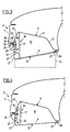
- la figure 3 est une vue schématique de côté illustrant la structure interne du pare-chocs représenté sur la figure 2, dans la position basse du spoiler ;
- la figure 4 est une vue analogue à la figure 3, où le spoiler est représenté dans sa position haute ;
- la figure 5 est une vue analogue aux figures 2 et 3, où le spoiler est représenté dans une position intermédiaire entre sa position haute et sa position escamotée ;
- la figure 6 est une vue analogue aux figures 3 à 5, où le spoiler est représenté dans sa position escamotée.
- une position haute dans laquelle le spoiler 8 saille au moins partiellement du bouclier 7 vers le bas, position qu'il occupe à basse vitesse pour permettre au véhicule 1 de surmonter certains obstacles, et
- une position basse, située sous la position haute, dans laquelle le spoiler 8 prolonge le bouclier 7 vers le bas et se trouve, en pratique, à proximité du sol, position qu'il occupe à vitesse élevée pour diminuer le coefficient de traínée du véhicule 1 et ainsi créer un effet de sol.
- une position avant dans laquelle sa paroi avant 10 est plaquée contre la cloison avant 13 du bâti 5, position qu'il occupe dans sa position escamotée, ainsi que dans ses positions haute et basse et dans toute position intermédiaire entre ces deux dernières, et
- une position arrière dans laquelle sa paroi avant 10 est suffisamment écartée de la cloison avant 13 du bâti 5 pour que le spoiler 8 puisse librement passer de sa position escamotée à sa position haute, et vice-versa.
Claims (11)
- Pare-chocs de véhicule automobile, qui comporte un bouclier (7) ainsi qu'un spoiler (8) articulé entre deux positions d'équilibre stable, à savoir une position haute dans laquelle il saille au moins partiellement du bouclier (7) vers le bas, et une position basse dans laquelle il prolonge le bouclier (7) vers le bas, caractérisé en ce que le spoiler (8) est apte à adopter une troisième position d'équilibre stable, dite position escamotée, dans laquelle il se trouve totalement escamoté derrière le bouclier (7).
- Pare-chocs selon la revendication 1, caractérisé en ce que le spoiler (8) est monté à la fois pivotant autour d'un axe transversal, et coulissant suivant une direction longitudinale entre une position avant dans laquelle il se trouve à proximité du bouclier (7), et une position arrière dans laquelle il est écarté de celui-ci.
- Pare-chocs selon la revendication 1 ou 2, caractérisé en ce qu'il comporte un mécanisme de débrayage (25) propre, sous certaines conditions dites d'escamotage, à permettre le passage du spoiler (8) de sa position haute vers sa position escamotée et, sous certaines conditions dites de déploiement, à permettre le passage du spoiler (8) de sa position escamotée vers sa position haute.
- Pare-chocs selon les revendications 2 et 3, prises conjointement, caractérisé en ce que le mécanisme de débrayage (25) est apte à commander le passage du spoiler (8) de sa position avant vers sa position arrière, et vice-versa.
- Pare-chocs selon la revendication 4, caractérisé en ce que ledit mécanisme de débrayage (25) comporte une tige (28) qui, par une extrémité dite interne, est en prise coulissante avec le spoiler (8), la tige (28) étant montée coulissante entre une position déployée dans laquelle elle entraíne le spoiler (8) vers sa position avant, et une position rétractée dans laquelle elle permet au spoiler (8) d'occuper sa position arrière.
- Pare-chocs selon la revendication 5, caractérisé en ce que le mécanisme de débrayage (25) comporte un ressort de rappel (34) qui sollicite en permanence la tige (28) vers sa position déployée.
- Pare-chocs selon l'une des revendications 1 à 6, caractérisé en ce qu'il comporte une butée (22) qui limite la course du spoiler vers le haut, cette butée (22) étant apte à empêcher le passage du spoiler (8) de sa position haute vers sa position escamotée.
- Pare-chocs selon l'une des revendications 1 à 7, caractérisé en ce qu'il définit, derrière le bouclier (7), un logement (24), et en ce que le spoiler (8) présente, vers l'avant, une lèvre (21) qui, en position escamotée, vient se placer dans ledit logement (24) pour maintenir le spoiler (8) en position escamotée.
- Pare-chocs selon l'une des revendications 1 à 8, caractérisé en ce qu'il comporte un dispositif de rappel (16) qui sollicite en permanence le spoiler (8) vers le haut.
- Pare-chocs selon la revendication 9, caractérisé en ce que ledit dispositif de rappel (16) comporte un ressort de traction (17) ancré sur le spoiler (8), ce ressort (17) étant taré pour permettre le passage du spoiler (8) de sa position haute vers sa position basse, et vice-versa, en fonction de la vitesse du véhicule.
- Pare-chocs selon l'une des revendications 1 à 10, caractérisé en ce qu'il comporte une butée (19) qui limite la course du spoiler (8) vers le bas.
Applications Claiming Priority (2)
| Application Number | Priority Date | Filing Date | Title |
|---|---|---|---|
| FR0212197 | 2002-10-02 | ||
| FR0212197A FR2845334B1 (fr) | 2002-10-02 | 2002-10-02 | Pare-chocs de vehicule comportant un spoiler articule entre trois positions d'equilibre stable |
Publications (2)
| Publication Number | Publication Date |
|---|---|
| EP1405783A1 true EP1405783A1 (fr) | 2004-04-07 |
| EP1405783B1 EP1405783B1 (fr) | 2005-08-10 |
Family
ID=31985401
Family Applications (1)
| Application Number | Title | Priority Date | Filing Date |
|---|---|---|---|
| EP03292395A Expired - Lifetime EP1405783B1 (fr) | 2002-10-02 | 2003-09-29 | Pare-chocs de véhicule comportant un spoiler articulé entre trois positions d'équilibre stable |
Country Status (5)
| Country | Link |
|---|---|
| US (1) | US6886883B2 (fr) |
| EP (1) | EP1405783B1 (fr) |
| DE (1) | DE60301241T2 (fr) |
| ES (1) | ES2245437T3 (fr) |
| FR (1) | FR2845334B1 (fr) |
Cited By (3)
| Publication number | Priority date | Publication date | Assignee | Title |
|---|---|---|---|---|
| US7380869B2 (en) | 2006-01-16 | 2008-06-03 | Toyota Jidosha Kabushiki Kaisha | Aerodynamic device for vehicle |
| FR3012107A1 (fr) * | 2013-10-23 | 2015-04-24 | Renault Sa | Structure avant de vehicule automobile equipee d'un spoiler mobile dispose sous le bouclier |
| FR3103166A1 (fr) * | 2019-11-15 | 2021-05-21 | Renault S.A.S | Dispositif déflecteur aérodynamique d’un véhicule automobile |
Families Citing this family (44)
| Publication number | Priority date | Publication date | Assignee | Title |
|---|---|---|---|---|
| US6874842B2 (en) * | 2002-06-24 | 2005-04-05 | General Motors Corporation | Air deflector for attachment to a lower surface of a vehicle and method for producing the same |
| US20050212310A1 (en) * | 2004-03-24 | 2005-09-29 | Viriyapanthu Paul Y | Device for protecting the front chin spoiler of an automobile |
| WO2006019270A1 (fr) * | 2004-08-19 | 2006-02-23 | Lg Chem. Ltd. | Dispositif lumineux organique comprenant une couche tampon et procede de fabrication correspondant |
| JP3952063B2 (ja) * | 2005-04-13 | 2007-08-01 | トヨタ自動車株式会社 | 車体下面空気流制御装置 |
| DE102005030419A1 (de) * | 2005-06-30 | 2007-01-04 | Daimlerchrysler Ag | Kraftfahrzeug mit einer Unterschutzeinrichtung |
| JP4301287B2 (ja) * | 2005-12-27 | 2009-07-22 | トヨタ自動車株式会社 | 車両用スパッツ装置 |
| US7780223B2 (en) * | 2007-08-09 | 2010-08-24 | Bayerische Motoren Werke Aktiengesellschaft | Aerodynamically activated front skirt for a vehicle |
| US8260519B2 (en) * | 2009-02-24 | 2012-09-04 | Nissan North America, Inc. | Retractable wheel covers |
| US8100460B2 (en) * | 2009-03-02 | 2012-01-24 | GM Global Technology Operations LLC | Extendable air control dam for vehicle |
| DE102009034906A1 (de) * | 2009-07-28 | 2011-02-03 | GM Global Technology Operations, Inc., Detroit | Vorderteil für eine Kraftfahrzeugkarosserie |
| US8186746B2 (en) * | 2010-02-01 | 2012-05-29 | GM Global Technology Operations LLC | Passively deployable air dam for a vehicle |
| US8292350B2 (en) * | 2010-04-26 | 2012-10-23 | GM Global Technology Operations LLC | Inflatable vehicle air dam with bidirectional deploy/stow system |
| DE102011111456B4 (de) * | 2011-08-30 | 2022-05-05 | Apollo Vredestein B.V. | Luftleiteinrichtung für ein Kraftfahrzeug |
| GB201216941D0 (en) * | 2012-09-21 | 2012-11-07 | Mclaren Automotive Ltd | Devices for controlling the down force generated by a vehicle |
| US8702152B1 (en) * | 2013-01-11 | 2014-04-22 | Ford Global Technologies, Llc | Deployable front air dam |
| US8950800B1 (en) | 2013-11-11 | 2015-02-10 | Ford Global Technologies, Llc | Deployable lower leg stiffener for pedestrian protection |
| WO2015143294A1 (fr) * | 2014-03-21 | 2015-09-24 | Magna International Inc. | Système de panneau latéral aérodynamique déployable |
| KR101583920B1 (ko) * | 2014-05-02 | 2016-01-13 | 현대자동차주식회사 | 차량용 프런트 스포일러 장치 |
| EP3154846B1 (fr) * | 2014-06-11 | 2019-02-20 | Magna Exteriors Inc. | Déflecteur avant actif |
| WO2015191711A2 (fr) * | 2014-06-11 | 2015-12-17 | Magna International Inc. | Déflecteur avant actif |
| KR102470561B1 (ko) * | 2014-06-11 | 2022-11-25 | 마그나 익스테리어즈 인크. | 능동형 전방 디플렉터 |
| GB2528925B (en) * | 2014-08-05 | 2018-05-30 | Jaguar Land Rover Ltd | Vehicle aerodynamic apparatus |
| EP3006249B1 (fr) * | 2014-10-06 | 2016-10-05 | C.R.F. Società Consortile per Azioni | Dispositif aérodynamique sous-corps pour un véhicule à moteur |
| KR101620225B1 (ko) * | 2014-12-01 | 2016-05-13 | 현대자동차주식회사 | 리어범퍼 멀티 캐리어의 언더커버 장치 |
| US10106210B2 (en) * | 2015-02-10 | 2018-10-23 | Ford Global Technologies Llc | Compact efficient system to quickly raise and slowly lower an air dam |
| DE102015105567A1 (de) * | 2015-04-13 | 2016-10-13 | Dr. Ing. H.C. F. Porsche Aktiengesellschaft | Kraftfahrzeugbugteil |
| US9517802B1 (en) * | 2015-09-04 | 2016-12-13 | GM Global Technology Operations LLC | Active underbody deflector |
| KR101966604B1 (ko) | 2015-09-23 | 2019-04-05 | 멀티매틱 인코퍼레이티드 | 차량용 내하중 스포일러 메커니즘 |
| GB2539984B (en) * | 2015-09-24 | 2017-05-17 | Ford Global Tech Llc | Deployable pedestrian safety device with membrane for vehicles |
| EP3178730B1 (fr) * | 2015-12-09 | 2019-01-30 | C.R.F. Società Consortile per Azioni | Dispositif aérodynamique pour véhicule à moteur |
| FR3044998B1 (fr) * | 2015-12-10 | 2018-03-23 | Valeo Systemes Thermiques | Dispositif deflecteur aerodynamique pour roue de vehicule automobile |
| US9821754B2 (en) * | 2016-02-26 | 2017-11-21 | Ford Global Technologies, Llc | Spring assist lock and release lower leg front-end stiffener |
| US10272957B2 (en) | 2016-12-06 | 2019-04-30 | Ford Global Technologies, Llc | Active tire spoiler system and method |
| FR3059978B1 (fr) * | 2016-12-13 | 2019-04-19 | Valeo Systemes Thermiques | Dispositif deflecteur aerodynamique pour roue de vehicule automobile |
| US10953844B2 (en) * | 2017-06-29 | 2021-03-23 | Ford Global Technologies, Llc | External airbag system for pedestrian protection |
| US10471914B2 (en) * | 2017-10-24 | 2019-11-12 | GM Global Technology Operations LLC | Deployable debris protection device for an automotive vehicle |
| FR3073809B1 (fr) * | 2017-11-22 | 2019-11-22 | Compagnie Plastic Omnium | Diffuseur arriere mobile de vehicule a panneau translatant |
| US11180203B2 (en) * | 2019-11-19 | 2021-11-23 | Ford Global Technologies, Llc | Active fascia splitter and engine shield |
| CN115892260A (zh) * | 2021-09-30 | 2023-04-04 | 本田技研工业株式会社 | 车体下部结构 |
| CN117818776A (zh) * | 2022-09-29 | 2024-04-05 | 本田技研工业株式会社 | 可动式扰流板装置 |
| CN115783070A (zh) * | 2022-12-16 | 2023-03-14 | 武汉路特斯汽车有限公司 | 一种车辆用气坝系统及车辆 |
| CN118205636A (zh) * | 2022-12-16 | 2024-06-18 | 武汉路特斯汽车有限公司 | 车辆空气动力学套件控制系统及车辆 |
| FR3162193A1 (fr) * | 2024-05-15 | 2025-11-21 | Stellantis Auto Sas | Caisson déformable escamotable pour véhicule automobile tout-terrain |
| CN118636985B (zh) * | 2024-08-16 | 2024-12-20 | 中国重汽集团济南动力有限公司 | 前端底部护板及车辆 |
Citations (2)
| Publication number | Priority date | Publication date | Assignee | Title |
|---|---|---|---|---|
| US4904016A (en) * | 1986-05-16 | 1990-02-27 | Nissan Motor Co., Ltd. | Front spoiler arrangement |
| EP1052151A2 (fr) * | 1999-05-08 | 2000-11-15 | Volkswagen Aktiengesellschaft | Pare-chocs de véhicules automobiles |
Family Cites Families (9)
| Publication number | Priority date | Publication date | Assignee | Title |
|---|---|---|---|---|
| US3618998A (en) * | 1970-04-15 | 1971-11-09 | Donald A Swauger | Windload applicator and stabilizer for steerable front wheels of rear-engined vehicles |
| US4119339A (en) * | 1976-09-10 | 1978-10-10 | Arthur Sherman Heimburger | Vehicle undercarriage air deflector |
| US4131308A (en) * | 1978-01-09 | 1978-12-26 | Ford Motor Company | Self-deploying chin spoiler for a vehicle |
| US4159140A (en) * | 1978-03-24 | 1979-06-26 | Ford Motor Company | Self-deployable air spoiler assembly |
| JPS6134224Y2 (fr) * | 1981-04-22 | 1986-10-06 | ||
| IT1153678B (it) * | 1982-12-10 | 1987-01-14 | Alfa Romeo Spa | Spoiler a posizionamento automatico per un autoveicolo |
| JPS63110078A (ja) * | 1986-10-27 | 1988-05-14 | Tsutomu Miwa | 下垂式エヤダムスカ−ト |
| US4976489A (en) * | 1990-03-26 | 1990-12-11 | General Motors Corporation | Air velocity responsive self deploying flexing air dam |
| US6196620B1 (en) * | 1999-03-19 | 2001-03-06 | William H. Haraway, Jr. | Aerodynamically responsive vehicular undercarriage safety spoiler system |
-
2002
- 2002-10-02 FR FR0212197A patent/FR2845334B1/fr not_active Expired - Fee Related
-
2003
- 2003-09-29 ES ES03292395T patent/ES2245437T3/es not_active Expired - Lifetime
- 2003-09-29 US US10/671,564 patent/US6886883B2/en not_active Expired - Fee Related
- 2003-09-29 EP EP03292395A patent/EP1405783B1/fr not_active Expired - Lifetime
- 2003-09-29 DE DE60301241T patent/DE60301241T2/de not_active Expired - Lifetime
Patent Citations (2)
| Publication number | Priority date | Publication date | Assignee | Title |
|---|---|---|---|---|
| US4904016A (en) * | 1986-05-16 | 1990-02-27 | Nissan Motor Co., Ltd. | Front spoiler arrangement |
| EP1052151A2 (fr) * | 1999-05-08 | 2000-11-15 | Volkswagen Aktiengesellschaft | Pare-chocs de véhicules automobiles |
Cited By (4)
| Publication number | Priority date | Publication date | Assignee | Title |
|---|---|---|---|---|
| US7380869B2 (en) | 2006-01-16 | 2008-06-03 | Toyota Jidosha Kabushiki Kaisha | Aerodynamic device for vehicle |
| FR3012107A1 (fr) * | 2013-10-23 | 2015-04-24 | Renault Sa | Structure avant de vehicule automobile equipee d'un spoiler mobile dispose sous le bouclier |
| WO2015059377A1 (fr) | 2013-10-23 | 2015-04-30 | Renault | Structure avant de vehicule automobile equipee d'un spoiler mobile dispose sous le bouclier |
| FR3103166A1 (fr) * | 2019-11-15 | 2021-05-21 | Renault S.A.S | Dispositif déflecteur aérodynamique d’un véhicule automobile |
Also Published As
| Publication number | Publication date |
|---|---|
| FR2845334A1 (fr) | 2004-04-09 |
| DE60301241D1 (de) | 2005-09-15 |
| FR2845334B1 (fr) | 2004-11-19 |
| US6886883B2 (en) | 2005-05-03 |
| US20040113457A1 (en) | 2004-06-17 |
| DE60301241T2 (de) | 2006-03-23 |
| ES2245437T3 (es) | 2006-01-01 |
| EP1405783B1 (fr) | 2005-08-10 |
Similar Documents
| Publication | Publication Date | Title |
|---|---|---|
| EP1405783B1 (fr) | Pare-chocs de véhicule comportant un spoiler articulé entre trois positions d'équilibre stable | |
| EP3350006B1 (fr) | Ensemble avant ou arrière de véhicule automobile présentant une ouverture et comprenant un volet flexible pour obturer ladite ouverture | |
| EP3390209B2 (fr) | Dispositif déflecteur aérodynamique pour roue de véhicule automobile | |
| EP2882633B1 (fr) | Dispositif deflecteur et vehicule automobile dont le bouclier avant porte ledit dispositif deflecteur | |
| FR3056185B1 (fr) | Becquet arriere d’un vehicule | |
| WO2019063730A1 (fr) | Dispositif déflecteur de véhicule automobile | |
| EP2013074B1 (fr) | Dispositif de couverture modulable pour vehicule terrestre | |
| FR2791630A1 (fr) | Vehicule automobile a element aerodynamique escamotable | |
| EP0799730B1 (fr) | Système de remorquage pour au moins un véhicule tracteur et un véhicule tracté et véhicule automobile pouvant être utilisé dans ce système | |
| EP3060455B1 (fr) | Structure avant de vehicule automobile equipee d'un spoiler mobile dispose sous le bouclier | |
| EP1060976A1 (fr) | Bouclier à bavette inférieure mobile | |
| WO2012080602A1 (fr) | Partie avant de vehicule, tel qu'un vehicule automobile, a securite amelioree en cas de choc pieton | |
| EP3812216A1 (fr) | Caméra de recul escamotable dans un becquet mobile | |
| EP2750968B1 (fr) | Deflecteur anti-projections pour atterrisseur d'aeronef | |
| FR2982567A1 (fr) | Becquet arriere mobile de vehicule | |
| FR2681821A1 (fr) | Dispositif reflechissant associe a la partie arriere d'un vehicule automobile. | |
| FR2768389A1 (fr) | Vehicule motorise 2 roues comportant un toit retractable ou decapotable, un plancher en deux parties dont une escamotable et deux portes laterales degondables | |
| FR2623151A3 (fr) | Dispositif hydraulique pour deplacer un vehicule automobile | |
| EP1675740B1 (fr) | Dispositif de deflexion de air pour vehicule a toit ouvrant | |
| EP1238863B1 (fr) | Elément de carrosserie à structure gonflable protégeant des chocs à basse vitesse | |
| FR2467093A1 (fr) | Dispositif de suspension avant pour vehicules automobiles | |
| FR2728198A1 (fr) | Pare-soleil extensible pour vehicule automobile | |
| FR2818606A1 (fr) | Dispositif a chenille pour circulation en terrain accidente | |
| FR3162193A1 (fr) | Caisson déformable escamotable pour véhicule automobile tout-terrain | |
| FR2714347A1 (fr) | Dispositif de freinage contrôlé pour engin du type à chenille. |
Legal Events
| Date | Code | Title | Description |
|---|---|---|---|
| PUAI | Public reference made under article 153(3) epc to a published international application that has entered the european phase |
Free format text: ORIGINAL CODE: 0009012 |
|
| AK | Designated contracting states |
Kind code of ref document: A1 Designated state(s): AT BE BG CH CY CZ DE DK EE ES FI FR GB GR HU IE IT LI LU MC NL PT RO SE SI SK TR |
|
| AX | Request for extension of the european patent |
Extension state: AL LT LV MK |
|
| 17P | Request for examination filed |
Effective date: 20041007 |
|
| AKX | Designation fees paid |
Designated state(s): DE ES FR GB IT |
|
| GRAP | Despatch of communication of intention to grant a patent |
Free format text: ORIGINAL CODE: EPIDOSNIGR1 |
|
| GRAA | (expected) grant |
Free format text: ORIGINAL CODE: 0009210 |
|
| GRAS | Grant fee paid |
Free format text: ORIGINAL CODE: EPIDOSNIGR3 |
|
| AK | Designated contracting states |
Kind code of ref document: B1 Designated state(s): DE ES FR GB IT |
|
| REG | Reference to a national code |
Ref country code: GB Ref legal event code: FG4D Free format text: NOT ENGLISH |
|
| REF | Corresponds to: |
Ref document number: 60301241 Country of ref document: DE Date of ref document: 20050915 Kind code of ref document: P |
|
| GBT | Gb: translation of ep patent filed (gb section 77(6)(a)/1977) |
Effective date: 20050923 |
|
| REG | Reference to a national code |
Ref country code: ES Ref legal event code: FG2A Ref document number: 2245437 Country of ref document: ES Kind code of ref document: T3 |
|
| PLBE | No opposition filed within time limit |
Free format text: ORIGINAL CODE: 0009261 |
|
| STAA | Information on the status of an ep patent application or granted ep patent |
Free format text: STATUS: NO OPPOSITION FILED WITHIN TIME LIMIT |
|
| 26N | No opposition filed |
Effective date: 20060511 |
|
| PGFP | Annual fee paid to national office [announced via postgrant information from national office to epo] |
Ref country code: IT Payment date: 20130930 Year of fee payment: 11 |
|
| PG25 | Lapsed in a contracting state [announced via postgrant information from national office to epo] |
Ref country code: IT Free format text: LAPSE BECAUSE OF NON-PAYMENT OF DUE FEES Effective date: 20140929 |
|
| PGFP | Annual fee paid to national office [announced via postgrant information from national office to epo] |
Ref country code: ES Payment date: 20151028 Year of fee payment: 13 |
|
| REG | Reference to a national code |
Ref country code: FR Ref legal event code: PLFP Year of fee payment: 14 |
|
| REG | Reference to a national code |
Ref country code: FR Ref legal event code: PLFP Year of fee payment: 15 |
|
| PG25 | Lapsed in a contracting state [announced via postgrant information from national office to epo] |
Ref country code: ES Free format text: LAPSE BECAUSE OF NON-PAYMENT OF DUE FEES Effective date: 20160930 |
|
| REG | Reference to a national code |
Ref country code: FR Ref legal event code: PLFP Year of fee payment: 16 |
|
| PGFP | Annual fee paid to national office [announced via postgrant information from national office to epo] |
Ref country code: FR Payment date: 20180926 Year of fee payment: 16 Ref country code: DE Payment date: 20180920 Year of fee payment: 16 |
|
| REG | Reference to a national code |
Ref country code: ES Ref legal event code: FD2A Effective date: 20181126 |
|
| PGFP | Annual fee paid to national office [announced via postgrant information from national office to epo] |
Ref country code: GB Payment date: 20180919 Year of fee payment: 16 |
|
| REG | Reference to a national code |
Ref country code: DE Ref legal event code: R119 Ref document number: 60301241 Country of ref document: DE |
|
| PG25 | Lapsed in a contracting state [announced via postgrant information from national office to epo] |
Ref country code: DE Free format text: LAPSE BECAUSE OF NON-PAYMENT OF DUE FEES Effective date: 20200401 |
|
| GBPC | Gb: european patent ceased through non-payment of renewal fee |
Effective date: 20190929 |
|
| PG25 | Lapsed in a contracting state [announced via postgrant information from national office to epo] |
Ref country code: FR Free format text: LAPSE BECAUSE OF NON-PAYMENT OF DUE FEES Effective date: 20190930 Ref country code: GB Free format text: LAPSE BECAUSE OF NON-PAYMENT OF DUE FEES Effective date: 20190929 |