EP1404991B1 - Stegeinheit - Google Patents
Stegeinheit Download PDFInfo
- Publication number
- EP1404991B1 EP1404991B1 EP02751121A EP02751121A EP1404991B1 EP 1404991 B1 EP1404991 B1 EP 1404991B1 EP 02751121 A EP02751121 A EP 02751121A EP 02751121 A EP02751121 A EP 02751121A EP 1404991 B1 EP1404991 B1 EP 1404991B1
- Authority
- EP
- European Patent Office
- Prior art keywords
- frame
- elements
- web
- profiling
- frame unit
- Prior art date
- Legal status (The legal status is an assumption and is not a legal conclusion. Google has not performed a legal analysis and makes no representation as to the accuracy of the status listed.)
- Expired - Lifetime
Links
- 230000005540 biological transmission Effects 0.000 claims abstract description 73
- 230000008878 coupling Effects 0.000 claims description 12
- 238000010168 coupling process Methods 0.000 claims description 12
- 238000005859 coupling reaction Methods 0.000 claims description 12
- 230000008859 change Effects 0.000 claims description 4
- 230000002250 progressing effect Effects 0.000 abstract 1
- 230000000284 resting effect Effects 0.000 abstract 1
- 238000013461 design Methods 0.000 description 12
- 238000012546 transfer Methods 0.000 description 6
- 238000009434 installation Methods 0.000 description 4
- 238000000034 method Methods 0.000 description 3
- 230000008569 process Effects 0.000 description 3
- 238000003860 storage Methods 0.000 description 3
- 238000004519 manufacturing process Methods 0.000 description 2
- 239000000463 material Substances 0.000 description 2
- 238000003825 pressing Methods 0.000 description 2
- 230000009467 reduction Effects 0.000 description 2
- 230000003716 rejuvenation Effects 0.000 description 2
- XAGFODPZIPBFFR-UHFFFAOYSA-N aluminium Chemical compound [Al] XAGFODPZIPBFFR-UHFFFAOYSA-N 0.000 description 1
- 229910052782 aluminium Inorganic materials 0.000 description 1
- 230000008901 benefit Effects 0.000 description 1
- 150000001875 compounds Chemical class 0.000 description 1
- 230000006835 compression Effects 0.000 description 1
- 238000007906 compression Methods 0.000 description 1
- 238000010276 construction Methods 0.000 description 1
- 238000012937 correction Methods 0.000 description 1
- 238000011161 development Methods 0.000 description 1
- 238000006073 displacement reaction Methods 0.000 description 1
- 238000009826 distribution Methods 0.000 description 1
- 230000000694 effects Effects 0.000 description 1
- 230000006872 improvement Effects 0.000 description 1
- 230000003993 interaction Effects 0.000 description 1
- 238000005304 joining Methods 0.000 description 1
- 238000012545 processing Methods 0.000 description 1
- 230000007480 spreading Effects 0.000 description 1
- 238000003892 spreading Methods 0.000 description 1
- 230000002459 sustained effect Effects 0.000 description 1
- 238000002834 transmittance Methods 0.000 description 1
Images



Classifications
-
- F—MECHANICAL ENGINEERING; LIGHTING; HEATING; WEAPONS; BLASTING
- F16—ENGINEERING ELEMENTS AND UNITS; GENERAL MEASURES FOR PRODUCING AND MAINTAINING EFFECTIVE FUNCTIONING OF MACHINES OR INSTALLATIONS; THERMAL INSULATION IN GENERAL
- F16H—GEARING
- F16H57/00—General details of gearing
- F16H57/08—General details of gearing of gearings with members having orbital motion
- F16H57/082—Planet carriers
-
- F—MECHANICAL ENGINEERING; LIGHTING; HEATING; WEAPONS; BLASTING
- F16—ENGINEERING ELEMENTS AND UNITS; GENERAL MEASURES FOR PRODUCING AND MAINTAINING EFFECTIVE FUNCTIONING OF MACHINES OR INSTALLATIONS; THERMAL INSULATION IN GENERAL
- F16H—GEARING
- F16H1/00—Toothed gearings for conveying rotary motion
- F16H1/28—Toothed gearings for conveying rotary motion with gears having orbital motion
- F16H1/48—Special means compensating for misalignment of axes, e.g. for equalising distribution of load on the face width of the teeth
Definitions
- the invention relates to a web unit for a planetary gear, in detail with the features of the preamble of claim 1.
- Planetary gear sets are mainly used in applications, at which high speeds and powers coaxial with high power density to be transferred. Due to the increasing demands on the Transmittance gains the rigidity of a planetary gear set in terms on tooth corrections more and more important. Significant influence on the Overall rigidity of the planetary gear set has the design of the web.
- a split bridge comprising one with the Drive side rotatably coupled bridge element and one with the output side rotatably coupled web element, the rotationally fixed to each other in the axial Direction extending and arranged in the circumferential direction, as a stepped bolt executed transmission elements coupled and braced in the axial direction are, lead the occurring under load deformations of the individual coupled elements to a very unsatisfactory Width carrying capacity of stored in the web planetary gears with this associated teeth on solar and / or Hohlrädem, from what Damage to the teeth can result. Also by increase the axial compression can not solve this problem.
- a generic web unit is known from the publication DE-A-19945242 previously known. This comprises a first web element and a second web element, which extend over each other in the axial direction and a theoretical connection axis descriptive transmission elements rotatably coupled and clamped in the axial direction. These web elements are as Fineblanking parts produced.
- Two each arranged on the web shaft Guide discs are about rivet pins in a press in one operation thereby connected to each other, that in the shoulders of the studded Rivet bolt ring teeth are incorporated and that the guide discs in Direction of the shoulder acting tool of each press with a adapted ring tooth is provided. This is in every functional condition the assembly given a flat concern of the individual parts together.
- This embodiment of the web unit is characterized by a very high rigidity of the Planet wheel set characterized.
- the generated due to the joining process However, tension of the individual elements to be coupled together also leads Here under load occurring deformations of the individual with each other coupled elements that contribute to a reduced bearing capacity of the the planet gear mounted with the gear teeth associated with this lead to sun and / or ring gears, resulting in damage to the teeth can result.
- the invention is therefore based on the object, a web unit of the above mentioned type such that with this a stiff Planetary gear set design and optimum load-bearing behavior of the individual Gear elements is guaranteed.
- the web unit for planetary gear sets for storage of planetary gears comprises a first web element and a second web element which overlap one another extending in the axial direction and a theoretical connection axis descriptive transmission or connecting elements rotationally fixed coupled and clamped in the axial direction.
- Each transfer relationship Connecting element has areas of different radial Dimensions on, with the resulting and the individual Web elements directed end faces of these areas each contact surfaces - a first and a second contact surface - which form either directly or via an intermediate element of the mutually facing end faces of the Web elements formed contact surfaces in so-called contact areas issue.
- the profiling is in radially outer region through at least one region of greater axial Extension as in the direction of the transmission or Connecting element describable theoretical connection axis between characterized the two web elements.
- the single transfer relationship way Connecting element or only part of the mecanics redesigning elements serves to support the planet gears as well as non-rotatable coupling of the two web elements.
- the contact areas forming partial surfaces of the contact surfaces extend in the unloaded State, i. free from torque transmission over part of each facing end faces of web element and transmission element. The to this subsequent surface of the facing end faces of Bar element and transmission element is free of this functional condition a touch with each other.
- the contact areas are strained in the process State between web and transmission element and unloaded state of the Web unit, i.
- the solution according to the invention thus prevents a simple means Divergence of the individual components in the contact area during deformation the web elements and ensures a stiff web construction and thus optimal conditions for the storage of planetary gears to the To secure the width capacity of the toothing in all functional states.
- the Profiling allows not only an external contact surface but also a contact surface uniform plant and thus a distribution of the necessary force to Press on a larger area. This allows you to get bigger ones Realize forces for pressing, without due to partial achievement or Above the yield limits, above all under load, the risk of setting is exceeded and to do so with the lock of the connection.
- low-grade materials used such as aluminum. Even with out of process security set external system of the bolt is due to the larger area and the better support to the sustained pressure after assembly and especially during operation less. In order to a lower load on the materials is to be expected.
- the profiling can on the web element and / or on the transmission element be executed. According to a further development, this can also be achieved by a Intermediate element are generated, which between transmission element or the formed by cross-sectional change and the web elements directed contact surfaces and the web elements is arranged and the Transmission or connecting element in the circumferential direction at least partially encloses and at his, each directly to one Web element directed Simseite forms a contact surface.
- the contact areas exist in each case between web element and intermediate element and Intermediate element and transmission element. Again, at least one of Surfaces of a contact area formed with an intermediate element with a Profiling provided.
- the profiling is also in the radially outer region by at least one region of greater axial extent than in the direction of through the transmission element theoretical connection axis between the characterized both web elements.
- each intermediate element is located completely in the other contact area on the adjacent element.
- the Intermediate element is preferably between transmission element and Stem element clamped or by means of press connection with the Transmission element connected.
- the solution with the intermediate element has the advantage that standardized here Transmission elements and web elements can be used and no additional processing of this is required and only by the choice of insects also compensated for deformations of different sizes can be.
- the profiling can be achieved by constant cross-sectional change in the range of Contact surface in the direction of the theoretical connection axis or else make sudden changes.
- the profiling is for example as in axial Direction aligned projection or in the cross section of web element, Transmission element or intermediate element viewed through in the direction of characterized by the transfer element theoretical Joint axis executed cross-sectional taper formed.
- the transmission or connection element can be varied be executed.
- the different radial dimensions on the outer circumference be realized by designing a stepped bolt.
- This can be as integral unit or be formed of several individual parts. in the the first case, the execution of the stepped bolt depends on the type of Mounting.
- This can by appropriate design of at least an end portion of the stepped bolt with a thread by means of fixation for example, take a ring nut.
- Another embodiment is at least a portion in the end with an internal thread too provided, which hineinerstreckt in installation position in the web elements.
- the Fixation can then take place on the web element associated cover disc, which has a passage opening for guiding a fastening element, for example, in the form of a screw, with two-sided execution the end portions of the stepped bolt brought about a strain in this way can be.
- a fastening element for example, in the form of a screw
- the end portions of the stepped bolt brought about a strain in this way can be.
- tensions with by the Realized stepped bolt guided clamping elements This is the step bolt in Although this case in one piece, but designed as Jardinnbolzenhülsenelement.
- a clamping screw can be performed, which is either supported directly in a web element or an intermediate element and on another web element is secured by means of a ring nut.
- Another Possibility is to pass through the sleeve a clamping bolt, wherein this is secured on both sides via corresponding ring nuts.
- this includes, for example, a first bearing sleeve, preferably by a, over its axial extent unchangeable diameter is characterized and another second Bearing bush, which serves to support the planetary gear and the area larger radial dimension describes.
- the second bearing bush will open the first bearing bush raised. Between the two is preferably a Press fit selected.
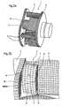
- FIGS 2a and 2b illustrate with reference to an embodiment of a web. 1
- the web 1 in this case comprises a first web element, which as first cheek 2 is called and with the input or output side when used in a planetary gear in a drive train is coupled, and a second Web element, which is referred to as second cheek 3.
- the second cheek 3 is in accordance with the connection of the first cheek to the arrival or Output side with the Ab- or drive side coupled.
- the two cheeks - first Cheek 2 and second cheek 3 - are via means 4 for axial coupling connected together in the axial direction.
- the funds 4 can be executed differently.
- these include Transmission or connection elements 5, which are preferably in considered uniform intervals in the circumferential direction of the cheeks 2 and 3 are arranged. These transfer load from the drive side cheek to driven-side cheek.
- the first cheek 2 acts as drive side cheek and the second cheek 3 as the output side cheek.
- there is a high part of the load over the transmission or Transfer elements 5 to the output side cheek creating a Deformation of the drive side cheek 2 is caused.
- With increased Power transmission can do this in addition to a gap between the Transmission or connecting elements 5 and the cheeks, especially the first cheek 2 lead. This gaping is in enlarged Representation based on a section of an execution of a split Bridge 1 shown in Figure 2a.
- the transmission elements 5 are usually as a stepped bolt. 6 executed.
- the area of smaller diameter extends through the cheek.
- the End faces 8 and 9 of the stepped bolt 6 in the region of the larger diameter 7 are each directed to the first cheek 2 or second cheek 3 out.
- FIG. 2 b shows clearly that the gaping between the with each other under axial tension operatively engageable face 9 and the end face 11 of the second output side cheek 3 occurs.
- the connecting elements that is first cheek 2 and second cheek 3 occur Problems with the carrying capacity of the gearing on.
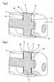
- FIG. 1 a illustrates a section of a divided web 1 in FIG a sectional view through a transmission element 5 a first embodiment an inventive design of the profiling of the contact surfaces of individual elements which can be brought into operative connection with one another under load Bridge 1.
- the basic structure corresponds to that already described in Figure 2.
- the web 1 comprises a first cheek 2 and a second cheek 3, which each with the input or output side when used in a planetary gear in a drive train can be coupled.
- the two cheeks - first cheek 2 and second cheek 3 - are in the axial direction with each other by means of the fourth coupled.
- the means 4 include transmission or Connecting elements 5, which are designed in the form of stepped bolts 6.
- Stepped bolt 6 in this case comprises a region of larger diameter 7, which in axial direction to the two cheeks - drive side cheek 2 and the output side cheek 3 - at least indirectly adjacent, that is, in the axial Direction aligned end faces 10 and 11 of the anRICmoi output side cheek 2 and 3 directly or indirectly touch.
- the end faces 8 and 9 act in the area larger diameter 7 of the stepped bolt 6 and facing each other End faces 10 and 11 of the on or driven side cheek 2 and 3 directly as contact surfaces.
- the contact surfaces are at 12a and 12b on Stepped bolt designates, wherein the contact surface 12a in the unloaded state a part of the end face 8 corresponds, while the possible contact surface 12b the end face 9 corresponds.
- the contact surfaces at the on or on the output side cheek elements acting surfaces are doing by the End face 10 of the first cheek 2 in the form of the contact surface 13 and the End face 11 formed on the second cheek 3 in the form of the contact surface 14.
- the facing contact surfaces here the contact surfaces 12a and 13 and the contact surfaces 12b and 14 thereby describe the torque load free state, i. in the assembled state contact areas 15 and 16, wherein the Contact area 15 by the operatively engageable with each other Surface regions on the contact surfaces 12a and 13 can be described while the Contact area 16 by the operatively engageable with each other Surface areas on the contact surfaces 12b and 14 between the stepped bolt. 6 and the second cheek 3 is writable.
- FIG. 1a illustrates an embodiment with a Profiling 17 and 18 at the contact surfaces 12a and 12b in the region of larger diameter 7 of the stepped bolt 6. This is there executed in such a way that it is viewed in cross-section in the axial direction in radial direction from the area of the outer diameter 19 of the area larger diameter 7 of the stepped bolt to the axis A of the stepped bolt.
- the profiling of the range of Outer circumference 19 in the region of larger diameter to the outer periphery 22 (Fig.1) in the range of smaller diameter or smaller dimensions extends in the radial direction of the transmission element 5. It is essential only that the profiling in installation position in the web 1 in the radial direction considered over a portion of the possible contact surface 13th or 14 on the drive side cheek 2 and the output side cheek 3 extends, but under load, a touch of the End face 8 or 9 in the region of larger diameter of the Stepped bolt 6 with the end faces 10 and 11 of the first cheek. 2 or second cheek 3 is avoided.
- the profiling designed such that they themselves viewed in the radial direction in installation position in cross section over the radial Extension of at least one of the elements to be coupled together - first Cheek 2 or second cheek 3 - in the contact area 15 and 16, respectively extends.
- this relates to the profiling 18, which in radial Direction has a larger outer diameter 20 than that Outer diameter 21 of the second cheek 3 in the contact area 16.
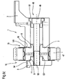
- Figures 1b and 1c illustrate further possible embodiments of a Profiling of the contact surfaces on the end faces 8 and 9 im Area of the region of larger diameter 7 than the stepped bolt. 6 executed transmission or connection element 5.
- the profiling is such executed that the transmission or connecting element in Area of larger diameter 7 for the above part substantially has a trapezoidal cross-section, the area being larger Diameter 7 from the outer periphery 19 to the axis A of the transmission element rejuvenated.
- the rejuvenation extends to the Outer circumference 22 of the transmission element 5, in particular of the stepped bolt 6 in the area of larger diameter 7 free area 23 respectively 24. That is, the above formed by the area of larger diameter 7 above Part has in cross-section in the axial direction on the outer circumference 19 larger Dimensions on than on the outer circumference 22 of the area 7 free area 23rd
- FIG. 1c illustrates a further embodiment of the profiling of FIG Contact surfaces 12a and 12b, which, for example, from the End faces 8 and 9 are formed.
- This is viewed in cross section through a region of greater axial extension 25 in the radially outer region, the is called in the region of the outer periphery 19 of the protruding part on Stepped bolt 6 is formed and further has an area lesser axial extension 26, which in the radial direction between the Outer circumference 22 of the area of larger diameter 7 free area 23rd or 24 and the region of greater axial extent 25 is arranged is.
- the region of greater axial extent 25 is thereby of in Circumferentially formed, preferably over the entire circumference extending and viewed in the axial direction in cross section in the installed position the cheeks protrusions formed.
- Figures 1a to 1c illustrate only the basic principle of Arrangement according to the invention of a profiling on as contact surfaces acting end faces 8 and 9 of the stepped bolt 6 during use as a transfer element 5 in a split web design 1.
- Other Profiles are also conceivable. It is essential only that the profiling in the radially outer region of the transmission element 5 has a larger axial Has extension, as in the radially inner region.
- Concrete embodiments of Profilings are in accordance with the erfordemisses and the Possibilities of production at the discretion of the competent expert.
- FIG. 3 illustrates a further second embodiment of the possibility of Providing a profiled design of the contact surfaces of each other Coupling elements of a split bridge design 1.
- the basic structure of the Web essentially corresponds to that described in FIGS. 1 and 2, Therefore, the same reference numerals are used for the same elements.
- the profiling in Contact area 15 or 16 between the area larger Diameter 7 on the stepped bolt 6 and the first cheek 2 and the second cheek 3 to provide the cheeks 2 and 3 respectively.
- the profile, denoted here by 27 or 28 is in each case at the end face 10th the first cheek 2 and the end face 11 of the second cheek 3 are arranged.
- the Profiling is designed such that in the radially outer region of the Cheeks 2 and 3 have a greater axial extent than in the radial inner area. In a cross-sectional view, this means that the first Cheek 2 and the second cheek 3 in the radial direction to the axis of the Transmission or connection elements A towards tapering are executed.
- the profiling 27 and 28 may be in Circumferential direction by a circumferentially extending projection be formed or by a plurality of such projections, the means there are a plurality of individual contact surfaces in the circumferential direction formed with the contact surfaces 12a and 12b on Transmission element 5, in particular the stepped bolt 6 in operative connection to step.
- This active compound is characterized by a plurality of Surface contacts allows.
- an embodiment is selected which viewed in the circumferential direction, a flat contact surface on the End faces 10 and 11 of the cheeks 2 and 3 forms.
- FIG. 4 illustrates a third possibility of a profiled embodiment of the invention coupled and operatively connected elements of a split bridge version 1.
- the basic structure also corresponds to that in the Figures 1 to 3 described, which is why the same for the same elements Reference numerals are used.
- the realization of the contacting takes place via profiled contact surfaces with the help of each of an intermediate element 29 or 30 between the mutually engageable surface areas on the end faces. 8 on the transmission element 5 and 10 on the first cheek 2 and the Intermediate member 30 on the end face 9 on the transmission element 5 and 11 at the second cheek 3.
- This design allows conventional to use unmodified studs 6 and still with the Solution according to the invention to be achieved effect of greater rigidity of Bridge version to allow.
- This solution is therefore characterized by a low design and manufacturing effort and can without considerable additional effort in already existing split web versions to get integrated.
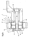
- Figures 5a and 5b illustrate with reference to a sectional view Possibilities for the realization of the axial connection of two web elements via a transmission element 5 in the form of a stepped bolt 6 and to the axial Strain.
- the transmission element 5 is here as a one-piece stepped bolt. 6 executed. This has a region of radially larger diameter 7, wherein due to the cross-sectional changes of this area, the two end faces 10th and 11 forms. The end faces come on the end faces 8 and 9 of the two Web elements 2 and 3 in the contact areas 15 and 16 for concern.
- the stepped bolt 6 with a profiling 17 and 18 executed at the corresponding end faces 10 and 11.
- the step bolt it carries a planetary gear 47th
- the axial tension between the Transmission or connecting element 5 and the web elements. 2 and FIG. 3 is realized via axial clamping means 31, wherein the means 31 in FIG Case shown a screw 32, which by the two web elements 2 and 3 and the stepped bolt 6 is guided and on a web element, here the Bar element 2 directly or as shown here indirectly via an intermediate element 33, which shows the position of the screw 32 in the axial direction towards the web element 3 fixed and limits the displacement in this direction.
- a cover plate 34 is provided, which rests on the web element 3 and a Internal thread has.
- the embodiment according to Figure 5a illustrates a Design with profiling on the transmission element 5. However, it is also conceivable an additional or alternative embodiment of the profiling on the end faces eighth and 9 of the web elements 2 and 3, respectively.
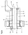
- FIG. 5b illustrates a further embodiment possibility of a web unit 1, comprising two web elements 2 and 3 with a Neills redesigntagen Connecting element 5 in the form of a stepped bolt 6.
- Der Stepped bolt 6 is here also made in one piece and extends in the axial Direction in installation position in each case in the web elements 2 and 3, which to have this purpose through holes 35 and 36.
- the fuse and axial clamping takes place in this embodiment by screwing means so-called ring nuts 37 and 38, which on both sides of the End portions 39 and 40 of the stepped bolt 6 are screwed.
- the stepped bolt 6 in its two end regions 39 and 40th designed as a pin, which is provided with a thread and on which a ring nut can be screwed 37 and 38, which is attached to the web element 2 or 3 is supported.
- the profiling is 17 or 18 on the transmission or connection element 5 trained and in the case illustrated by a continuous cross-sectional reduction viewed in the axial direction from the radially outer periphery 19 in the direction of tapering theoretical connection axis of the connecting element executed.
- a corresponding Profiling on the web elements 3 and 2 are provided.
- FIGS. 6a to 6c illustrate this with respect to embodiments Transmission or connection element 5 in the form of a Stepped bolt 6, but this is made of several parts.
- the stepped bolt 6 comprises a first bearing sleeve 41 and a second bearing sleeve 42.
- the first bearing sleeve 41 extends in axial Direction until each in the range of the axial extent of the two Bar elements 2 and 3 or beyond this.
- the first bearing sleeve 41 designed as a cylindrical element 43, which in the area one of its two ends a cylindrical shoulder 44 in the form of a flange having.
- the projection formed by the cylindrical shoulder 44 serves for supporting on one of the two web elements 2 or 3, in the case shown on the web element 3, wherein this in a recess in the form of a bore 45th intervenes.
- the bearing sleeve 41 a Thread on, which is executed in the illustrated case as an external thread, on which a ring nut 46 can be mounted, which in turn on Web element 2 is supported.
- the second bearing sleeve 42 forms the area larger radial diameter 7, which also the storage of the planetary gear 47th serves. Between the bearing sleeve 41 and the bearing sleeve 42 is a press fit intended.
- the bearing sleeve 42 carries in the illustrated case a profiling, which in the simplest case by a constant tapering of the axial dimensions in radial direction from the outer periphery 19 in the direction of the axis A of the Transmission or connecting element 5 is characterized.
- Conceivable here is an embodiment of the two facing each other End faces 8 and 9 of the two web elements 2 and 3 with a corresponding Profiling.
- the profiling can be carried out as in Figures 1 a to 1 c be.
- FIG. 6b illustrates a further embodiment of the transmission relationship Connecting element 5 in the form of a multi-part executed Stepped bolt 6 between two web elements 2 and 3.
- the axial coupling and Clamping is realized via corresponding fastening means 48, which in the case shown a screw 49 and for clamping the screw or fuse include a nut 50.
- a screw 49 and for clamping the screw or fuse include a nut 50.
- this is the case Transmission or connection element 5 from a first Bearing sleeve 41 and a second bearing sleeve 42, wherein both bearing sleeves in radial direction are braced against each other, preferably in the form of a Transverse pressure connection.
- the bearing sleeve 41 extends in the installed position in the Area of axial extent in a corresponding passage opening of the first web element 2 and the second web element 3 inside.
- the Connecting screw supports this via an intermediate element 51 on the first Bar element 2 from.
- the tension is then realized by means of the ring nut 50, which comes to rest on the other web element 3.
- FIG. 6c illustrates another possibility for realizing the axial Coupling and clamping of the elements web element 2, web element 3 and Transmission or connection element 5, which here as Stepped bolt 6 is made in one piece.
- This contributes in the area larger radial Diameter 7, the planetary gear 47 and extends in the area lower radial diameter in one of the web elements 2 or 3, in the illustrated case second into a corresponding passage opening.
- the tension is over Fastener 48, comprising a screw 49 extending over a Intermediate element 51 or directly on the web element 2 is supported.
- the function the ring nut takes over the web element 3, by this with a corresponding bore, preferably through hole 52 is provided which carries an internal thread.
- the web element 3 is such engineered that this at least two areas different Outside diameter 53 and 54, wherein the area is smaller Diameter 53 a support surface for the stepped bolt 6 in the radial direction forms.
- the stepped bolt 6 In the axial direction of the stepped bolt 6 forms with its end faces 10 and 11 or in this area adjacent partial surfaces of the End faces 8 and 9 of the two web elements 2 and 3, the contact areas 15 and 16.
- the stepped bolt 6 has the Profiling on its two end faces 10 and 11. It is also conceivable Execution of profiling on the two web elements 2 and 3.
- Figures 5 and 6 illustrate possible embodiments for the realization of axial coupling and clamping of the individual elements of a web unit 1 in Shape of the web elements 2 and 3 and the transmission or Connecting elements 5 by means of fastening means against each other.
Landscapes
- Engineering & Computer Science (AREA)
- General Engineering & Computer Science (AREA)
- Mechanical Engineering (AREA)
- Retarders (AREA)
- General Details Of Gearings (AREA)
- Saccharide Compounds (AREA)
Description
- Fig.1a - 1c
- verdeutlicht anhand eines Ausschnittes aus einem Steg eines Planetenradsatzes eine erste erfindungsgemäße Ausführung der Profilierung der Kontaktflächen der leistungsübertragenden Elemente;
- Figur 2a, Figur 2b
- verdeutlichen die Grundproblematik der Verformungen der Einzelelemente des Steges bei der Leistungsübertragung;
- Figur 3
- zeigt eine weitere erfindungsgemäße Ausführung der Profilierung der Kontaktflächen der miteinander in Wirkverbindung tretenden Elemente eines Steges in Form einer Profilierung der Stegelemente;
- Figur 4
- zeigt anhand eines Ausschnittes aus einem Steg eine weitere Ausgestaltung der Profilierung der Kontaktflächen der einzelnen miteinander in Wirkverbindung tretenden Elemente eines Steges am Beispiel der Profilierung mittels Zwischenstück;
- Figur 5a, Figur 5b
- verdeutlichen Möglichkeiten zur axialen Kopplung und Verspannung mit einem Übertragungselement in Form eines einteiligen Stufenbolzens;
- Fig. 6a - 6c
- verdeutlichen Möglichkeiten zur axialen Kopplung und Verspannung mit einem Übertragungselement in Form eines mehrteilig ausgeführten Stufenbolzens.
- 1
- Stegeinheit
- 2
- erstes Stegelement; erste Wange
- 3
- zweites Stegelement; zweite Wange
- 4
- Mittel zur axialen Kopplung zwischen erster Wange und zweiter Wange
- 5
- Übertragungselemente
- 6
- Stufenbolzen
- 7
- Bereich größeren Durchmessers am Stufenbolzen
- 8
- Stirnseite
- 9
- Stirnseite
- 10
- Stirnfläche
- 11
- Stirnfläche
- 12a, 12b
- Kontaktfläche am Stufenbolzen
- 13
- Kontaktfläche an der ersten Wange 2
- 14
- Kontaktfläche an der zweiten Wange 3
- 15
- Kontaktbereich
- 16
- Kontaktbereich
- 17
- Profilierung
- 18
- Profilierung
- 19
- Bereich des Außenumfanges im Bereich größeren Durchmessers 7 am Stufenbolzen 6
- 20
- Außenumfang der Profilierung 17
- 21
- Außenumfang der Profilierung 18
- 22
- Außenumfang
- 23
- vom Bereich 7 freier Bereich
- 24
- vom Bereich 7 größeren Durchmessers freier Bereich
- 25
- Bereich größerer axialer Erstreckung
- 26
- Zwischenbereich
- 27
- Profil
- 28
- Profil
- 29
- Zwischenelement
- 30
- Zwischenelement
- 31
- Mittel zur axialen Verspannung
- 32
- Schraube
- 33
- Zwischenelement
- 34
- Deckscheibe
- 35
- Durchgangsöffnung
- 36
- Durchgangsöffnung
- 37
- Ringmutter
- 38
- Ringmutter
- 39
- Endbereich
- 40
- Endbereich
- 41
- Lagerhülse
- 42
- Lagerhülse
- 43
- zylindrisches Element
- 44
- zylindrischer Absatz
- 45
- Ausnehmung
- 46
- Ringmutter
- 47
- Planetenrad
- 48
- Befestigungsmittel
- 49
- Schraube
- 50
- Mutter
- 51
- Zwischenelement
- 52
- Durchgangsöffnung
- 53
- Bereich
- 54
- Bereich
Claims (15)
- Stegeinheit (1) für Planetenradsätze zur Lagerung von Planetenrädern;1.1 mit einem ersten Stegelement (2) und einem zweiten Stegelement (3), welche miteinander über sich in axialer Richtung erstreckende und eine theoretische Verbindungsachse beschreibende Übertragungselemente (5) drehfest gekoppelt und in axialer Richtung verspannbar sind;1.2 jedes Übertragungselement (5) weist Bereiche (7) unterschiedlicher radialer Abmessungen auf, wobei die daraus gebildeten und zu den einzelnen Stegelementen (2, 3) gerichteten Stirnflächen (11, 10) dieser Bereiche jeweils Kontaktflächen (12a, 12b) - eine erste (12a) und eine zweite Kontaktfläche (12b) - bilden, welche direkt oder über ein Zwischenelement (29, 30) an von den zueinander weisenden Stirnseiten (8, 9) der Stegelemente (2, 3) gebildeten weiteren Kontaktflächen (13, 14) teilweise in Kontaktbereichen (15, 16) anliegen;1.3 wenigstens eine Teilfläche einer Kontaktfläche (12a, 12b, 13, 14) eines Kontaktbereiches (15, 16) wird von einer Profilierung (17, 18) gebildet;1.4 die Profilierung (17, 18) ist im radial äußeren Bereich (19) durch mindestens einen Bereich größerer axialer Erstreckung in Richtung der durch das Übertragungselement (5) theoretischen Verbindungsachse zwischen den beiden Stegelementen (2,3) charakterisiert, gekennzeichnet durch die folgenden Merkmale:1.5 die weiteren Kontaktflächen (13, 14) entsprechen im unbelasteten Zustand der stegeinheit (1) einem Teil der stirnflächen (10,11).
- Stegeinheit (1) nach Anspruch 1, dadurch gekennzeichnet, daß die Profilierung (17, 18) am Stegelement (2) ausgeführt ist.
- Stegeinheit (1) nach Anspruch 1 oder 2, dadurch gekennzeichnet, daß die Profilierung (17, 18) am Übertragungselement (5) ausgeführt ist.
- Stegeinheit (1) nach einem der Ansprüche 1 bis 3, gekennzeichnet durch die folgenden Merkmale:4.1 das Übertragungselement (5) ist als Stufenbolzen (6) ausgeführt;4.2 die Kontaktfläche (12a, 12b) am Stufenbolzen (6) wird direkt an den aufgrund der Querschnittsveränderung gebildeten Stirnflächen (10, 11) des Stufenbolzens (6) gebildet.
- Stegeinheit (1) nach Anspruch 4, dadurch gekennzeichnet, daß das Übertragungselement (5) einteilig ausgeführt ist und die drehfeste Kopplung und Verspannung in axialer Richtung über Mittel (31) zur axialen Verspannung realisiert wird.
- Stegeinheit (1) nach Anspruch 5, gekennzeichnet durch die folgenden Merkmale:6.1 das Übertragungselement (5) erstreckt sich in seinen, vom Bereich größeren Durchmessers (7) freien Bereichen in Durchgangsöffnungen der Stegelemente (2, 3) wenigstens teilweise hinein oder über diese in axialer Richtung hinaus;6.2 die Mittel (31) zur axialen Verspannung umfassen mindestens ein Schraubelement (32) und eine Ringmutter (34);6.3 das Schraubelement (32) stützt sich im Bereich seines Kopfes an einem der Stegelemente (2, 3) ab und ist durch das erste Stegelement (2), das Übertragungselement (5) und das zweite Stegelement (3) geführt;6.4 die Ringmutter (34) stützt sich am jeweils anderen Stegelement (3, 2) ab.
- Stegeinheit (1) nach Anspruch 5, gekennzeichnet durch die folgenden Merkmale:7.1 das Übertragungselement (5) erstreckt sich in seinen, vom Bereich größeren Durchmessers (7) freien Bereichen in Durchgangsöffnungen der Stegelemente (2, 3) wenigstens teilweise hinein oder über diese in axialer Richtung hinaus;7.2 die Mittel (31) zur axialen Verspannung umfassen mindestens einen gewindetragenden Endbereich am Übertragungselement (5), welcher mit einer Ringmutter (38, 37) zusammenwirkt und sich am Stegelement (2, 3) abstützt.
- Stegeinheit (1) nach Anspruch 4, dadurch gekennzeichnet, daß das Übertragungselement (5) aus mehreren Einzelelementen besteht und die drehfeste Kopplung und Verspannung in axialer Richtung über Mittel (31) zur drehfesten Kopplung und axialen Verspannung realisiert wird.
- Stegeinheit (1) nach Anspruch 8, gekennzeichnet durch die folgenden Merkmale:9.1 das Übertragungselement (5) umfaßt zwei Lagerhülsen, eine erste Lagerhülse (41) und eine zweite Lagerhülse (42);9.2 eine der beiden Lagerhülsen (41, 42) - erste Lagerhülse (41) oder zweite Lagerhülse (42) - umschließt die jeweils andere Lagerhülse (42, 41) in Umfangsrichtung und bildet den Bereich größeren Durchmessers (7) des Übertragungselementes (5).
- Stegeinheit (1) nach Anspruch 9, dadurch gekennzeichnet, daß die Mittel (31) zur axialen Verspannung mindestens einen, gewindetragenden Endbereich der ersten Lagerhülse (41) und eine, mit diesem zusammenwirkende Ringmutter umfassen, welche sich in axialer Richtung an einem Stegelement (2, 3) abstützt.
- Stegeinheit (1) nach Anspruch 10, dadurch gekennzeichnet, daß der andere Endbereich der ersten Lagerhülse (41) einen zylindrischen Absatz (44) umfaßt, welcher sich in axialer Richtung an der vom Übertragungselement (5) weggerichteten Stirnseite des Stegelementes (40) abstützt.
- Stegeinheit (1) nach einem der Ansprüche 9 bis 11, dadurch gekennzeichnet, daß die Mittel (31) zur axialen Verspannung ein Schraubelement (49) umfassen, welches sich in axialer Richtung durch die Lagerhülsen (41, 42) erstreckt und dessen Kopfelement sich an einem der Stegelemente (2, 3) abstützt, wobei die Sicherung am anderen Stegelement (3, 2) durch eine Ringmutter (50) erfolgt.
- Stegeinheit (1) nach Anspruch 1 bis 12, gekennzeichnet durch die folgenden Merkmale:13.1 das Übertragungselement (5) ist als Stufenbolzen (6) ausgeführt;13.2 zwischen den aufgrund der Querschnittsveränderung gebildeten Stirnflächen (10, 11) und den Stegelementen (2, 3) ist jeweils mindestens ein Zwischenelement (29, 30) angeordnet, welches aufgrund seiner Ausgestaltung die Profilierung (17, 18) bildet.
- Stegeinheit (1) nach einem der Ansprüche 1 bis 13, dadurch gekennzeichnet, daß die Profilierung (17, 18) durch eine sprungartige Querschnittsveränderung des eine Kontaktfläche (12a, 12b, 13, 14) bildenden Elementes (5, 6, 2, 3, 29, 30) erzeugt wird.
- Stegeinheit (1) nach einem der Ansprüche 1 bis 14, dadurch gekennzeichnet, daß die Profilierung durch eine stetige Querschnittsveränderung des die Kontaktfläche (12a, 12b, 13, 14) bildenden Elementes (5, 6, 2, 3, 29, 30) erzeugt wird.
Applications Claiming Priority (3)
| Application Number | Priority Date | Filing Date | Title |
|---|---|---|---|
| DE10133703 | 2001-07-11 | ||
| DE10133703A DE10133703A1 (de) | 2001-07-11 | 2001-07-11 | Stegeinheit |
| PCT/EP2002/007579 WO2003008843A1 (de) | 2001-07-11 | 2002-07-08 | Stegeinheit |
Publications (2)
| Publication Number | Publication Date |
|---|---|
| EP1404991A1 EP1404991A1 (de) | 2004-04-07 |
| EP1404991B1 true EP1404991B1 (de) | 2005-10-05 |
Family
ID=7691404
Family Applications (1)
| Application Number | Title | Priority Date | Filing Date |
|---|---|---|---|
| EP02751121A Expired - Lifetime EP1404991B1 (de) | 2001-07-11 | 2002-07-08 | Stegeinheit |
Country Status (6)
| Country | Link |
|---|---|
| US (1) | US7144348B2 (de) |
| EP (1) | EP1404991B1 (de) |
| JP (1) | JP4077407B2 (de) |
| AT (1) | ATE306033T1 (de) |
| DE (2) | DE10133703A1 (de) |
| WO (1) | WO2003008843A1 (de) |
Families Citing this family (4)
| Publication number | Priority date | Publication date | Assignee | Title |
|---|---|---|---|---|
| DE102006049996A1 (de) * | 2006-10-24 | 2008-04-30 | Zf Friedrichshafen Ag | Planetenrad-Einheit und Verfahren zur Herstellung einer Planetenrad-Einheit |
| GB0807778D0 (en) * | 2008-04-29 | 2008-06-04 | Romax Technology Ltd | Apparatus and method for improving radial stresses in a gear transmission mounting |
| US20150105212A1 (en) * | 2013-10-14 | 2015-04-16 | Caterpillar Inc. | System and method for salvaging a pin-bore assembly |
| DE102019216385A1 (de) * | 2019-10-24 | 2020-08-27 | Zf Friedrichshafen Ag | Zahnrad mit verjüngter Axialgleitfläche |
Family Cites Families (12)
| Publication number | Priority date | Publication date | Assignee | Title |
|---|---|---|---|---|
| FR1005218A (fr) * | 1947-06-18 | 1952-04-08 | Mathis | Perfectionnements apportés aux systèmes d'engrenages, notamment à planétaires et satellites |
| FR1089588A (fr) * | 1953-09-14 | 1955-03-18 | Batignolles Chatillon | Perfectionnements apportés aux trains épicycloïdaux |
| JPH0617714B2 (ja) * | 1985-11-11 | 1994-03-09 | 株式会社大金製作所 | 遊星歯車変速機の遊星キヤリア |
| ATE47623T1 (de) * | 1986-03-26 | 1989-11-15 | Wittenstein Manfred | In den umlauftraeger eines planetengetriebes einsetzbarer planetenradbolzen. |
| IT1223952B (it) | 1988-11-30 | 1990-09-29 | Magneti Marelli Spa | Riduttore epicicloidale particolarmente per motorini di avviamento per motori a combustione interna |
| US5692989A (en) * | 1996-06-06 | 1997-12-02 | Kamlukin; Igor | Self aligning planetary gear transmission & speed reducer |
| US6106429A (en) * | 1999-05-17 | 2000-08-22 | Caterpillar Inc. | Thrust washer for a planetary gear assembly |
| DE19945242A1 (de) | 1999-09-21 | 2001-03-22 | Zahnradfabrik Friedrichshafen | Verfahren zur Herstellung eines Planetenträgers |
| DE10047308A1 (de) * | 2000-09-25 | 2002-05-02 | Ims Morat Soehne Gmbh | Zweistufige Getriebeanordnung |
| ATE367227T1 (de) * | 2001-01-12 | 2007-08-15 | Asar Group | Selbstpolierende und selbstschneidende nietanordnung |
| US20030008748A1 (en) * | 2001-06-28 | 2003-01-09 | Gerald Fox | Epicyclic gear system |
| US20030181284A1 (en) * | 2002-03-20 | 2003-09-25 | Tai-Shan Chen | Planet-gear speed reducer |
-
2001
- 2001-07-11 DE DE10133703A patent/DE10133703A1/de not_active Withdrawn
-
2002
- 2002-07-08 DE DE50204482T patent/DE50204482D1/de not_active Expired - Lifetime
- 2002-07-08 EP EP02751121A patent/EP1404991B1/de not_active Expired - Lifetime
- 2002-07-08 WO PCT/EP2002/007579 patent/WO2003008843A1/de not_active Ceased
- 2002-07-08 US US10/483,434 patent/US7144348B2/en not_active Expired - Fee Related
- 2002-07-08 AT AT02751121T patent/ATE306033T1/de not_active IP Right Cessation
- 2002-07-08 JP JP2003514152A patent/JP4077407B2/ja not_active Expired - Fee Related
Also Published As
| Publication number | Publication date |
|---|---|
| DE10133703A1 (de) | 2003-02-06 |
| DE50204482D1 (de) | 2005-11-10 |
| JP4077407B2 (ja) | 2008-04-16 |
| US20040171455A1 (en) | 2004-09-02 |
| EP1404991A1 (de) | 2004-04-07 |
| ATE306033T1 (de) | 2005-10-15 |
| US7144348B2 (en) | 2006-12-05 |
| JP2004535538A (ja) | 2004-11-25 |
| WO2003008843A1 (de) | 2003-01-30 |
Similar Documents
| Publication | Publication Date | Title |
|---|---|---|
| DE19900791B4 (de) | Verbindungselement für zwei Maschinen- oder Bauteile insbesondere Paß-Dehnschraube, Paß-Gewindebolzen o. dgl. | |
| EP3191313B1 (de) | Fahrzeugrad mit einer radfelge und einer radscheibe | |
| EP0316832A1 (de) | Getriebeteil für eine Wischanlage von Kraftfahrzeugen und Verfahren zu dessen Herstellung | |
| DE102015114440B4 (de) | Scheibenbremse mit Synchronisationseinheit | |
| EP0636217B1 (de) | Verfahren zum herstellen einer bremsscheibe für eine scheibenbremse | |
| WO1991007600A1 (de) | Konusspannsatz | |
| DE2708538C3 (de) | Verbindung zwischen den Kettengliedern einer Gleiskette | |
| DE102011050748B3 (de) | Verbindung eines Wellenstücks einer Lenkwelle für ein Kraftfahrzeug mit einem Anschlussteil | |
| DE4317579A1 (de) | Spannverbindung zwischen einer Hülse und einer Welle | |
| EP1404991A1 (de) | Stegeinheit | |
| DE10227971A1 (de) | Nabenring, Abdeckblech und Kupplungsscheibe | |
| DE10162910B4 (de) | Klemmspaltmutter | |
| DE102011050747B3 (de) | Verbindung eines Wellenstücks einer Lenkwelle für ein Kraftfahrzeug mit einem Anschlussteil | |
| DE10212671B4 (de) | Kegelradausgleichsgetriebe | |
| EP2059694B1 (de) | Getriebeanordnung mit axialer sicherung | |
| AT500716B1 (de) | Verfahren zur ausgestaltung eines verbindungselementes und verbindungselement | |
| DE102010030018B4 (de) | Drehbeschlag mit integrierter Bremsvorrichtung | |
| DE102007058523A1 (de) | Adapterelement sowie Verstellantrieb mit Adapterelement | |
| DE102021126919B3 (de) | Belastungsoptimierter Planetenträger mit planetenradlückenüberbrückender Welle-Nabe-Verbindung an beiden Trägerwangen sowie Planetengetriebe mit einem solchen Planetenträger | |
| DE3938445C1 (en) | Simple taper-lock bush assembly - incorporates equally spaced axial tension screws protruding through end flange on inner taper bush | |
| DE102019115868B4 (de) | Spindelantrieb | |
| WO2026061814A1 (de) | Sicherungsscheibe | |
| DE19814291A1 (de) | Schraube und Werkzeug zum Anziehen und Lösen von Muttern auf Schrauben | |
| WO2023052169A1 (de) | Getriebeanordnung | |
| EP4144615A1 (de) | Aktuator, lenksäule für ein kraftfahrzeug sowie verfahren zum herstellen und/oder montieren eines aktuators |
Legal Events
| Date | Code | Title | Description |
|---|---|---|---|
| PUAI | Public reference made under article 153(3) epc to a published international application that has entered the european phase |
Free format text: ORIGINAL CODE: 0009012 |
|
| 17P | Request for examination filed |
Effective date: 20031204 |
|
| AK | Designated contracting states |
Kind code of ref document: A1 Designated state(s): AT BE BG CH CY CZ DE DK EE ES FI FR GB GR IE IT LI LU MC NL PT SE SK |
|
| 17Q | First examination report despatched |
Effective date: 20040708 |
|
| GRAP | Despatch of communication of intention to grant a patent |
Free format text: ORIGINAL CODE: EPIDOSNIGR1 |
|
| GRAS | Grant fee paid |
Free format text: ORIGINAL CODE: EPIDOSNIGR3 |
|
| GRAA | (expected) grant |
Free format text: ORIGINAL CODE: 0009210 |
|
| AK | Designated contracting states |
Kind code of ref document: B1 Designated state(s): AT BE BG CH CY CZ DE DK EE ES FI FR GB GR IE IT LI LU MC NL PT SE SK |
|
| PG25 | Lapsed in a contracting state [announced via postgrant information from national office to epo] |
Ref country code: IE Free format text: LAPSE BECAUSE OF FAILURE TO SUBMIT A TRANSLATION OF THE DESCRIPTION OR TO PAY THE FEE WITHIN THE PRESCRIBED TIME-LIMIT Effective date: 20051005 Ref country code: IT Free format text: LAPSE BECAUSE OF FAILURE TO SUBMIT A TRANSLATION OF THE DESCRIPTION OR TO PAY THE FEE WITHIN THE PRESCRIBED TIME-LIMIT;WARNING: LAPSES OF ITALIAN PATENTS WITH EFFECTIVE DATE BEFORE 2007 MAY HAVE OCCURRED AT ANY TIME BEFORE 2007. THE CORRECT EFFECTIVE DATE MAY BE DIFFERENT FROM THE ONE RECORDED. Effective date: 20051005 Ref country code: FI Free format text: LAPSE BECAUSE OF FAILURE TO SUBMIT A TRANSLATION OF THE DESCRIPTION OR TO PAY THE FEE WITHIN THE PRESCRIBED TIME-LIMIT Effective date: 20051005 Ref country code: GB Free format text: LAPSE BECAUSE OF FAILURE TO SUBMIT A TRANSLATION OF THE DESCRIPTION OR TO PAY THE FEE WITHIN THE PRESCRIBED TIME-LIMIT Effective date: 20051005 Ref country code: SK Free format text: LAPSE BECAUSE OF FAILURE TO SUBMIT A TRANSLATION OF THE DESCRIPTION OR TO PAY THE FEE WITHIN THE PRESCRIBED TIME-LIMIT Effective date: 20051005 Ref country code: NL Free format text: LAPSE BECAUSE OF FAILURE TO SUBMIT A TRANSLATION OF THE DESCRIPTION OR TO PAY THE FEE WITHIN THE PRESCRIBED TIME-LIMIT Effective date: 20051005 Ref country code: CZ Free format text: LAPSE BECAUSE OF FAILURE TO SUBMIT A TRANSLATION OF THE DESCRIPTION OR TO PAY THE FEE WITHIN THE PRESCRIBED TIME-LIMIT Effective date: 20051005 |
|
| REG | Reference to a national code |
Ref country code: GB Ref legal event code: FG4D Free format text: NOT ENGLISH |
|
| REG | Reference to a national code |
Ref country code: CH Ref legal event code: EP |
|
| REG | Reference to a national code |
Ref country code: IE Ref legal event code: FG4D Free format text: LANGUAGE OF EP DOCUMENT: GERMAN |
|
| REF | Corresponds to: |
Ref document number: 50204482 Country of ref document: DE Date of ref document: 20051110 Kind code of ref document: P |
|
| PG25 | Lapsed in a contracting state [announced via postgrant information from national office to epo] |
Ref country code: SE Free format text: LAPSE BECAUSE OF FAILURE TO SUBMIT A TRANSLATION OF THE DESCRIPTION OR TO PAY THE FEE WITHIN THE PRESCRIBED TIME-LIMIT Effective date: 20060105 Ref country code: GR Free format text: LAPSE BECAUSE OF FAILURE TO SUBMIT A TRANSLATION OF THE DESCRIPTION OR TO PAY THE FEE WITHIN THE PRESCRIBED TIME-LIMIT Effective date: 20060105 Ref country code: DK Free format text: LAPSE BECAUSE OF FAILURE TO SUBMIT A TRANSLATION OF THE DESCRIPTION OR TO PAY THE FEE WITHIN THE PRESCRIBED TIME-LIMIT Effective date: 20060105 Ref country code: BG Free format text: LAPSE BECAUSE OF FAILURE TO SUBMIT A TRANSLATION OF THE DESCRIPTION OR TO PAY THE FEE WITHIN THE PRESCRIBED TIME-LIMIT Effective date: 20060105 |
|
| PG25 | Lapsed in a contracting state [announced via postgrant information from national office to epo] |
Ref country code: ES Free format text: LAPSE BECAUSE OF FAILURE TO SUBMIT A TRANSLATION OF THE DESCRIPTION OR TO PAY THE FEE WITHIN THE PRESCRIBED TIME-LIMIT Effective date: 20060116 |
|
| NLV1 | Nl: lapsed or annulled due to failure to fulfill the requirements of art. 29p and 29m of the patents act | ||
| PG25 | Lapsed in a contracting state [announced via postgrant information from national office to epo] |
Ref country code: PT Free format text: LAPSE BECAUSE OF FAILURE TO SUBMIT A TRANSLATION OF THE DESCRIPTION OR TO PAY THE FEE WITHIN THE PRESCRIBED TIME-LIMIT Effective date: 20060306 |
|
| GBV | Gb: ep patent (uk) treated as always having been void in accordance with gb section 77(7)/1977 [no translation filed] |
Effective date: 20051005 |
|
| REG | Reference to a national code |
Ref country code: IE Ref legal event code: FD4D |
|
| PG25 | Lapsed in a contracting state [announced via postgrant information from national office to epo] |
Ref country code: MC Free format text: LAPSE BECAUSE OF NON-PAYMENT OF DUE FEES Effective date: 20060731 Ref country code: LI Free format text: LAPSE BECAUSE OF NON-PAYMENT OF DUE FEES Effective date: 20060731 Ref country code: CH Free format text: LAPSE BECAUSE OF NON-PAYMENT OF DUE FEES Effective date: 20060731 Ref country code: BE Free format text: LAPSE BECAUSE OF NON-PAYMENT OF DUE FEES Effective date: 20060731 |
|
| PLBE | No opposition filed within time limit |
Free format text: ORIGINAL CODE: 0009261 |
|
| STAA | Information on the status of an ep patent application or granted ep patent |
Free format text: STATUS: NO OPPOSITION FILED WITHIN TIME LIMIT |
|
| 26N | No opposition filed |
Effective date: 20060706 |
|
| PG25 | Lapsed in a contracting state [announced via postgrant information from national office to epo] |
Ref country code: FR Free format text: LAPSE BECAUSE OF FAILURE TO SUBMIT A TRANSLATION OF THE DESCRIPTION OR TO PAY THE FEE WITHIN THE PRESCRIBED TIME-LIMIT Effective date: 20061020 |
|
| EN | Fr: translation not filed | ||
| REG | Reference to a national code |
Ref country code: CH Ref legal event code: PL |
|
| PG25 | Lapsed in a contracting state [announced via postgrant information from national office to epo] |
Ref country code: AT Free format text: LAPSE BECAUSE OF NON-PAYMENT OF DUE FEES Effective date: 20060708 |
|
| BERE | Be: lapsed |
Owner name: VOITH TURBO G.M.B.H. & CO. KG Effective date: 20060731 |
|
| PG25 | Lapsed in a contracting state [announced via postgrant information from national office to epo] |
Ref country code: EE Free format text: LAPSE BECAUSE OF FAILURE TO SUBMIT A TRANSLATION OF THE DESCRIPTION OR TO PAY THE FEE WITHIN THE PRESCRIBED TIME-LIMIT Effective date: 20051005 |
|
| PG25 | Lapsed in a contracting state [announced via postgrant information from national office to epo] |
Ref country code: LU Free format text: LAPSE BECAUSE OF NON-PAYMENT OF DUE FEES Effective date: 20060708 |
|
| PG25 | Lapsed in a contracting state [announced via postgrant information from national office to epo] |
Ref country code: FR Free format text: LAPSE BECAUSE OF FAILURE TO SUBMIT A TRANSLATION OF THE DESCRIPTION OR TO PAY THE FEE WITHIN THE PRESCRIBED TIME-LIMIT Effective date: 20051005 Ref country code: CY Free format text: LAPSE BECAUSE OF FAILURE TO SUBMIT A TRANSLATION OF THE DESCRIPTION OR TO PAY THE FEE WITHIN THE PRESCRIBED TIME-LIMIT Effective date: 20051005 |
|
| PGFP | Annual fee paid to national office [announced via postgrant information from national office to epo] |
Ref country code: DE Payment date: 20120809 Year of fee payment: 11 |
|
| PG25 | Lapsed in a contracting state [announced via postgrant information from national office to epo] |
Ref country code: DE Free format text: LAPSE BECAUSE OF NON-PAYMENT OF DUE FEES Effective date: 20140201 |
|
| REG | Reference to a national code |
Ref country code: DE Ref legal event code: R119 Ref document number: 50204482 Country of ref document: DE Effective date: 20140201 |