EP1404929B1 - Adjustment device and building element - Google Patents
Adjustment device and building element Download PDFInfo
- Publication number
- EP1404929B1 EP1404929B1 EP02737658A EP02737658A EP1404929B1 EP 1404929 B1 EP1404929 B1 EP 1404929B1 EP 02737658 A EP02737658 A EP 02737658A EP 02737658 A EP02737658 A EP 02737658A EP 1404929 B1 EP1404929 B1 EP 1404929B1
- Authority
- EP
- European Patent Office
- Prior art keywords
- stud
- grooves
- cam element
- pin
- base
- Prior art date
- Legal status (The legal status is an assumption and is not a legal conclusion. Google has not performed a legal analysis and makes no representation as to the accuracy of the status listed.)
- Expired - Lifetime
Links
Images






Classifications
-
- E—FIXED CONSTRUCTIONS
- E04—BUILDING
- E04B—GENERAL BUILDING CONSTRUCTIONS; WALLS, e.g. PARTITIONS; ROOFS; FLOORS; CEILINGS; INSULATION OR OTHER PROTECTION OF BUILDINGS
- E04B2/00—Walls, e.g. partitions, for buildings; Wall construction with regard to insulation; Connections specially adapted to walls
- E04B2/74—Removable non-load-bearing partitions; Partitions with a free upper edge
- E04B2/76—Removable non-load-bearing partitions; Partitions with a free upper edge with framework or posts of metal
- E04B2/78—Removable non-load-bearing partitions; Partitions with a free upper edge with framework or posts of metal characterised by special cross-section of the frame members as far as important for securing wall panels to a framework with or without the help of cover-strips
- E04B2/7809—Removable non-load-bearing partitions; Partitions with a free upper edge with framework or posts of metal characterised by special cross-section of the frame members as far as important for securing wall panels to a framework with or without the help of cover-strips of single or multiple tubular form
- E04B2/7818—Removable non-load-bearing partitions; Partitions with a free upper edge with framework or posts of metal characterised by special cross-section of the frame members as far as important for securing wall panels to a framework with or without the help of cover-strips of single or multiple tubular form of substantially rectangular form
-
- A—HUMAN NECESSITIES
- A47—FURNITURE; DOMESTIC ARTICLES OR APPLIANCES; COFFEE MILLS; SPICE MILLS; SUCTION CLEANERS IN GENERAL
- A47B—TABLES; DESKS; OFFICE FURNITURE; CABINETS; DRAWERS; GENERAL DETAILS OF FURNITURE
- A47B91/00—Feet for furniture in general
- A47B91/02—Adjustable feet
-
- E—FIXED CONSTRUCTIONS
- E04—BUILDING
- E04B—GENERAL BUILDING CONSTRUCTIONS; WALLS, e.g. PARTITIONS; ROOFS; FLOORS; CEILINGS; INSULATION OR OTHER PROTECTION OF BUILDINGS
- E04B2/00—Walls, e.g. partitions, for buildings; Wall construction with regard to insulation; Connections specially adapted to walls
- E04B2/74—Removable non-load-bearing partitions; Partitions with a free upper edge
- E04B2/82—Removable non-load-bearing partitions; Partitions with a free upper edge characterised by the manner in which edges are connected to the building; Means therefor; Special details of easily-removable partitions as far as related to the connection with other parts of the building
-
- E—FIXED CONSTRUCTIONS
- E04—BUILDING
- E04B—GENERAL BUILDING CONSTRUCTIONS; WALLS, e.g. PARTITIONS; ROOFS; FLOORS; CEILINGS; INSULATION OR OTHER PROTECTION OF BUILDINGS
- E04B9/00—Ceilings; Construction of ceilings, e.g. false ceilings; Ceiling construction with regard to insulation
- E04B9/22—Connection of slabs, panels, sheets or the like to the supporting construction
- E04B9/24—Connection of slabs, panels, sheets or the like to the supporting construction with the slabs, panels, sheets or the like positioned on the upperside of, or held against the underside of the horizontal flanges of the supporting construction or accessory means connected thereto
- E04B9/26—Connection of slabs, panels, sheets or the like to the supporting construction with the slabs, panels, sheets or the like positioned on the upperside of, or held against the underside of the horizontal flanges of the supporting construction or accessory means connected thereto by means of snap action of elastically deformable elements held against the underside of the supporting construction
-
- E—FIXED CONSTRUCTIONS
- E04—BUILDING
- E04C—STRUCTURAL ELEMENTS; BUILDING MATERIALS
- E04C3/00—Structural elongated elements designed for load-supporting
- E04C3/005—Girders or columns that are rollable, collapsible or otherwise adjustable in length or height
-
- E—FIXED CONSTRUCTIONS
- E04—BUILDING
- E04C—STRUCTURAL ELEMENTS; BUILDING MATERIALS
- E04C3/00—Structural elongated elements designed for load-supporting
- E04C3/30—Columns; Pillars; Struts
- E04C3/32—Columns; Pillars; Struts of metal
-
- F—MECHANICAL ENGINEERING; LIGHTING; HEATING; WEAPONS; BLASTING
- F16—ENGINEERING ELEMENTS AND UNITS; GENERAL MEASURES FOR PRODUCING AND MAINTAINING EFFECTIVE FUNCTIONING OF MACHINES OR INSTALLATIONS; THERMAL INSULATION IN GENERAL
- F16B—DEVICES FOR FASTENING OR SECURING CONSTRUCTIONAL ELEMENTS OR MACHINE PARTS TOGETHER, e.g. NAILS, BOLTS, CIRCLIPS, CLAMPS, CLIPS OR WEDGES; JOINTS OR JOINTING
- F16B12/00—Jointing of furniture or the like, e.g. hidden from exterior
- F16B12/02—Joints between panels and corner posts
-
- F—MECHANICAL ENGINEERING; LIGHTING; HEATING; WEAPONS; BLASTING
- F16—ENGINEERING ELEMENTS AND UNITS; GENERAL MEASURES FOR PRODUCING AND MAINTAINING EFFECTIVE FUNCTIONING OF MACHINES OR INSTALLATIONS; THERMAL INSULATION IN GENERAL
- F16M—FRAMES, CASINGS OR BEDS OF ENGINES, MACHINES OR APPARATUS, NOT SPECIFIC TO ENGINES, MACHINES OR APPARATUS PROVIDED FOR ELSEWHERE; STANDS; SUPPORTS
- F16M7/00—Details of attaching or adjusting engine beds, frames, or supporting-legs on foundation or base; Attaching non-moving engine parts, e.g. cylinder blocks
-
- E—FIXED CONSTRUCTIONS
- E06—DOORS, WINDOWS, SHUTTERS, OR ROLLER BLINDS IN GENERAL; LADDERS
- E06B—FIXED OR MOVABLE CLOSURES FOR OPENINGS IN BUILDINGS, VEHICLES, FENCES OR LIKE ENCLOSURES IN GENERAL, e.g. DOORS, WINDOWS, BLINDS, GATES
- E06B3/00—Window sashes, door leaves, or like elements for closing wall or like openings; Layout of fixed or moving closures, e.g. windows in wall or like openings; Features of rigidly-mounted outer frames relating to the mounting of wing frames
- E06B3/54—Fixing of glass panes or like plates
- E06B3/5427—Fixing of glass panes or like plates the panes mounted flush with the surrounding frame or with the surrounding panes
Definitions
- This invention relates to an adjustment device which is particularly useful in adjusting the vertical height of studs and the like in construction. While, for convenience, the invention will frequently be described below in this connection, it is to be understood that the invention is not limited in this way.
- the invention has broader application and can be used, for example, in connection with furniture assembly and as a levelling device for restaurant tables, refrigerators, washing machines, etc. Other applications are possible.
- This invention also relates to improved building elements useful in connection with the construction industry.
- the invention is applicable to the building of both internal walls and partitions and external walls, especially cladding. However, it is to be understood that the invention is not necessarily limited to these applications.
- An adjustment device is known from DE 323 158 C .
- the invention represents an advance on the invention disclosed in international patent application No. PCT/AU97/00681 ("the PCT Application").
- the PCT Application disclosed a building element being a stud.
- the stud had a first set of channels and a second set of channels. Each channel in each set was adapted to receive a co-operating means for the purpose of mounting a panel or bracket on the stud.
- the first set of channels was parallel to and spaced from the second set of channels.
- While the number of channels was not limited as to number, there were preferably three in each set. It was also preferred that the first set of channels was spaced from the second set of channels by a single web and this was illustrated in Figures 1 to 3, 6, 8,10 and 12 to 20 of the drawings.
- the PCT Application also disclosed a building element being a joining clip.
- the joining clip was adapted to mount a panel or bracket ;to the stud also disclosed in the PCT Application.
- the joining clip included the co-operating means (to be received in each channel of each set of the stud).
- the joining clip also included means for connecting the joining clip to the panel or bracket.
- the co-operating means included a pair of resilient arms.
- this invention provides an adjustment device according to claim 1.
- the cam element can be rotated to a position where the projection does not engage the grooves, the cam element can be set to different positions to effect coarse adjustment, and then rotated to engage the grooves and effect fine adjustment.
- the device of the invention is thus capable of being reset into different positions and so can accommodate a wide range of height adjustments.
- the cam element is designed so that a stud or other element with the adjustment device attached can be raised or lowered without the requirement to cause the full length of the pin to be engaged by the projection on the cam element.
- the pin in the adjustment device of the invention may be of any desired length. Although it is anticipated that the adjustment device of the invention may often be used to effect an adjustment of around 6-7 millimetres in the case of use in building construction, it is entirely feasible to use the adjustment device of the invention for far greater adjustment.
- the grooves on the pin are preferably inclined. These may form a screw thread or a series of inclined, parallel grooves on opposing sides of the pin.
- the cam element is designed so that rotation can be effected by an allan key or similar tool.
- the adjustment device of the invention includes biasing means, and especially when the device is inserted in a web of a stud, it is preferred that the adjustment device is supplied on site in a prestressed state. This may be achieved by engaging the cam element with one of the grooves, against the bias provided by the spring.
- the cam can be rotated to engage a groove above or below that of the original engagement, as desired, in order to elevate or lower the stud.
- the device includes a stop which can lock the cam in a desired position.
- the cam may be rotatable through a narrow arc for this purpose for example, less than 80°.
- the device is designed so that rotation through more than, say, 80°, will release engagement of the projection on the cam with the pin.
- the spring bias will then urge the cam away from the base to take up available height and the cam may then be rotated to engage another groove, to be subsequently locked in the new position.
- the adjustment device includes means, such as a spring, for biasing the cam element in relation to the base.
- the bias is away from the base.
- the adjustment device also may include means for locking the cam element in place once the desired distance between the base and the cam element has been achieved.
- the adjustment device may be designed to urge the cam element away from the base if the cam element is unlocked, through the influence of the biasing means.
- the adjustment device may be capable of adjustment to any desired extent.
- the adjustment device of the invention is particularly suitable for insertion in a stud or other building element, so that the vertical alignment of the stud can be adjusted by means of the adjusting device.
- the cam element is preferably inserted in a web of the stud, with the base supporting the stud on the floor of the building structure. Rotation of the cam element can enable the height of the stud to be adjusted upwardly or downwardly as desired.
- the adjustment device of the invention is preferably suitable for insertion in the building element described below.
- the stud of the PCT Application can be produced in an improved form if the first set of channels is spaced from the second set of channels by first and second webs, being spaced from each other.
- a modification of the stud can be produced to form a mullion which is particularly useful for external walls, especially in connection with glazed or cladding panels.
- the building element is suitable for use as a stud or mullion, the building element having a first set of two or more channels and a second set of channels, each channel in each set being adapted to receive a co-operating means for the purpose of mounting a panel or bracket on the building element, the first set of channels being parallel to and spaced from the second set of channels, each channel in the first set of channels having a base between a pair of sides, the bases of the channels in the first set of channels being aligned, characterised in that the first set of channels is spaced from the second set of channels by first and second webs, the first web being parallel to and spaced from the second web.
- the co-operating means may include a pair of resilient arms as disclosed in the PCT Application. Alternately or in addition the co-operating means may include a fastener capable of operating by remote activation as disclosed in International Patent Application No. PCT/AU99/00185 .
- the invention also provides the adjustment device of the invention to be combined with the building element, being the stud or mullion,
- the adjustment device of the invention is preferably inserted into the building element.
- adjustment device 10 is shown with base 12 supporting pin 14 which is upstanding from base 12.
- Pin 14 has a plurality of grooves 16, which in this case spiral around pin 14 in the form of a screw.
- Pin 14 also has end stop 18 (refer Figure 2) at the top of pin 14.
- Rotatable cam element 20 is adapted to be mounted on pin 14 and has internal protrusions (not shown) which are capable of engaging grooves 16 when cam element 20 is rotated Rotation of cam element 20 in one direction will cause it to climb up pin 14, while rotation in the reverse direction will cause cam element 20 to descend pin 14.
- Cam element 20 has hexagonal opening 22 for insertion of an allan key (not shown) or similar tool to facilitate rotation of cam element 20.
- Cam element 20 is made in two parts, 24 and 26. If it is desired to lock cam element 20 on pin 14, this can be achieved via screws 28.
- Adjustment device 10 is designed to fit into apertures 36 and 38 formed in webs 32 and 34 respectively and to be rotatable therein.
- cam element 20 on pin 14 will raise or lower stud 30 in relation to base 12, thus adjusting the height of stud 30 in situ as desired.
- pin 14 instead of having spiral screw grooves 16, is flat sided and has inclined grooves 42 on either side.
- Adjustment device 10 differs to that in Figure 3 in that it includes spring 44.
- Spring 44 is attached, at its upper end, to stud 30 by clip 46. The lower end of spring 44 rests on base 12. Spring 44 biases cam element 20 (and hence stud 30) away from base 12.
- spring 44 has been compressed and is held in that position by engagement of one of grooves 42 by protrusion 40 (not visible in these Figures, but refer Figure 3).
- protrusion 40 engages a groove 42, causing cam element 20 and hence stud 30 to change in distance from base 12. If cam element 20 is rotated in the direction shown by arrow 48, the distance increases. Reverse rotation decreases the distance.
- an internal stop 51 (refer Figure 12) (indicated externally by rivet 50) limits rotation in the direction of arrow 48 beyond about 80°. If at this stage further adjustment is required, rotation of cam element 20 in the direction opposite to that of arrow 48 will enable protrusion 40 to clear all grooves 42 and pin 14 is released from engagement with cam element 20.
- Spring 44 causes cam element 20 and stud 30 to elevate to the maximum allowable (determined by any horizontal surface above stud 30 and/or the length of spring 44 when unstressed). Rotation of cam element 20 in the direction of arrow 48 then causes protrusion 40 to engage a groove 42, to secure stud 30 in the desired position, under tension.
- protrusion 40 (Figure 3) is deliberately formed so as to leave a gap 41 within cam element 20. Gap 41 is sized to allow pin 14 to pass through cam element 20 when protrusion 40 is not in engagement with a groove 42.
- parts 24 and 26 of cam element 20 may be attached one to the other in any suitable way, including by pop riveting.
- stud 110 has channels 112 arranged in two sets of three. Each channel 112 has a base, 113. Each set of channels 112 is separated from the other by parallel webs 136 and 138 which include reinforcing ribs 140.
- Joining clip 116 is made of two parts, clip carrier 115 and clip 117.
- Clip carrier 115 is adapted to be attached by a screw or nail inserted between parts 120 and 121 through groove 131 into panel 118.
- Parts 120 and 121 on clip carrier 115 are adapted to push or slide into C-shaped channel 119 on clip 117.
- Clip 117 has co-operating means comprising resilient arms 114a and 114b which can be forward fitted into one of channels 112. Arms 114a and 114b carry grooves or serrations 126 which can lock into corresponding grooves 130 in the side walls of channel 112.
- Stud 110 includes further grooves 132 to reduce mass as well as screw locating grooves 134.
- the walls of channels 112 may be bifurcated to include large grooves 142 to assist in reducing mass.
- clip carrier 115 will be attached to panel 118 at the factory, transported to the site and there mated with clip 117 which in turn is then fitted into channel 112 of stud 110.
- stud 150 is similar to stud 110 and more clearly illustrates grooves 130,132 and 142. It will be noted, however, that stud 150 omits reinforcing ribs 140. Otherwise, stud 150 is very similar to stud 110.
- each arm of building element 190 is joined to a corresponding arm by webs 136 and 138.
- the adjustment device of the invention provides a convenient and efficient means to adjust the height of an element. It has ready application in the building industry, where it can provide adjustment for shortcomings in alignment or manufacture of studs, for example. It can enable the use of studs, for example, with a significant difference in height, in the same location. It can be used to level furniture and appliances, inter alia.
Landscapes
- Engineering & Computer Science (AREA)
- Architecture (AREA)
- Civil Engineering (AREA)
- Structural Engineering (AREA)
- General Engineering & Computer Science (AREA)
- Physics & Mathematics (AREA)
- Electromagnetism (AREA)
- Mechanical Engineering (AREA)
- Joining Of Building Structures In Genera (AREA)
- Load-Bearing And Curtain Walls (AREA)
- Legs For Furniture In General (AREA)
- Emergency Protection Circuit Devices (AREA)
- Road Signs Or Road Markings (AREA)
- Vehicle Body Suspensions (AREA)
- Control Of Motors That Do Not Use Commutators (AREA)
- Fluid-Damping Devices (AREA)
- Connection Of Plates (AREA)
Abstract
Description
- This invention relates to an adjustment device which is particularly useful in adjusting the vertical height of studs and the like in construction. While, for convenience, the invention will frequently be described below in this connection, it is to be understood that the invention is not limited in this way. The invention has broader application and can be used, for example, in connection with furniture assembly and as a levelling device for restaurant tables, refrigerators, washing machines, etc. Other applications are possible.
- This invention also relates to improved building elements useful in connection with the construction industry. The invention is applicable to the building of both internal walls and partitions and external walls, especially cladding. However, it is to be understood that the invention is not necessarily limited to these applications. An adjustment device is known from
DE 323 158 C . - In relation to the first aspect, in the construction industry, as well as in many other applications, it is desirable to provide adjustment up to a maximum of about 6-7mm. It is an aim of the present invention to provide a device which permits that quantum of adjustment, and which may also be useful, at least in some embodiments, to effect far more extreme adjustments, for example, of 50mm or more.
- It is also desirable to provide an adjustment device which can provide tension as well as or as an alternative to compression. In other words, it is desirable that the device be able to "pull" as well as "push", It is an aim of the present invention to provide such a device, at least in some embodiments.
- In a second aspect, the invention represents an advance on the invention disclosed in international patent application No.
PCT/AU97/00681 - The PCT Application disclosed a building element being a stud. The stud had a first set of channels and a second set of channels. Each channel in each set was adapted to receive a co-operating means for the purpose of mounting a panel or bracket on the stud. The first set of channels was parallel to and spaced from the second set of channels.
- While the number of channels was not limited as to number, there were preferably three in each set. It was also preferred that the first set of channels was spaced from the second set of channels by a single web and this was illustrated in Figures 1 to 3, 6, 8,10 and 12 to 20 of the drawings.
- The PCT Application also disclosed a building element being a joining clip. The joining clip was adapted to mount a panel or bracket ;to the stud also disclosed in the PCT Application. The joining clip included the co-operating means (to be received in each channel of each set of the stud). The joining clip also included means for connecting the joining clip to the panel or bracket. The co-operating means included a pair of resilient arms.
- In the first aspect, this invention provides an adjustment device according to claim 1.
- Because the cam element can be rotated to a position where the projection does not engage the grooves, the cam element can be set to different positions to effect coarse adjustment, and then rotated to engage the grooves and effect fine adjustment. The device of the invention is thus capable of being reset into different positions and so can accommodate a wide range of height adjustments.
- The cam element is designed so that a stud or other element with the adjustment device attached can be raised or lowered without the requirement to cause the full length of the pin to be engaged by the projection on the cam element.
- The pin in the adjustment device of the invention may be of any desired length. Although it is anticipated that the adjustment device of the invention may often be used to effect an adjustment of around 6-7 millimetres in the case of use in building construction, it is entirely feasible to use the adjustment device of the invention for far greater adjustment.
- The grooves on the pin are preferably inclined. These may form a screw thread or a series of inclined, parallel grooves on opposing sides of the pin.
- Preferably, the cam element is designed so that rotation can be effected by an allan key or similar tool.
- When the adjustment device of the invention includes biasing means, and especially when the device is inserted in a web of a stud, it is preferred that the adjustment device is supplied on site in a prestressed state. This may be achieved by engaging the cam element with one of the grooves, against the bias provided by the spring. On site, when it is desired to adjust the stud (to make up a minor or major discrepancy in height), the cam can be rotated to engage a groove above or below that of the original engagement, as desired, in order to elevate or lower the stud. Preferably, the device includes a stop which can lock the cam in a desired position. The cam may be rotatable through a narrow arc for this purpose for example, less than 80°.
- In this embodiment, if it is decided on site that a greater height adjustment is required, the device is designed so that rotation through more than, say, 80°, will release engagement of the projection on the cam with the pin. The spring bias will then urge the cam away from the base to take up available height and the cam may then be rotated to engage another groove, to be subsequently locked in the new position.
- Preferably, the adjustment device includes means, such as a spring, for biasing the cam element in relation to the base. Preferably, the bias is away from the base. The adjustment device also may include means for locking the cam element in place once the desired distance between the base and the cam element has been achieved. The adjustment device may be designed to urge the cam element away from the base if the cam element is unlocked, through the influence of the biasing means. Depending on the length of the pin and the chosen location of the grooves, the adjustment device may be capable of adjustment to any desired extent.
- The adjustment device of the invention is particularly suitable for insertion in a stud or other building element, so that the vertical alignment of the stud can be adjusted by means of the adjusting device. In this situation, the cam element is preferably inserted in a web of the stud, with the base supporting the stud on the floor of the building structure. Rotation of the cam element can enable the height of the stud to be adjusted upwardly or downwardly as desired. The adjustment device of the invention is preferably suitable for insertion in the building element described below.
- It has now been found that the stud of the PCT Application can be produced in an improved form if the first set of channels is spaced from the second set of channels by first and second webs, being spaced from each other.
- It has also been found that a modification of the stud can be produced to form a mullion which is particularly useful for external walls, especially in connection with glazed or cladding panels.
- The building element is suitable for use as a stud or mullion, the building element having a first set of two or more channels and a second set of channels, each channel in each set being adapted to receive a co-operating means for the purpose of mounting a panel or bracket on the building element, the first set of channels being parallel to and spaced from the second set of channels, each channel in the first set of channels having a base between a pair of sides, the bases of the channels in the first set of channels being aligned, characterised in that the first set of channels is spaced from the second set of channels by first and second webs, the first web being parallel to and spaced from the second web.
- The co-operating means may include a pair of resilient arms as disclosed in the PCT Application. Alternately or in addition the co-operating means may include a fastener capable of operating by remote activation as disclosed in International Patent Application No.
PCT/AU99/00185 - The invention also provides the adjustment device of the invention to be combined with the building element, being the stud or mullion, The adjustment device of the invention is preferably inserted into the building element.
- The invention will now be described in connection with certain embodiments thereof described in connection with the accompanying drawings. It is to be understood that these embodiments are not intended to he limiting on the scope of the invention.
- In the drawings:
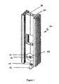
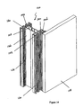
- Figure 1 is a perspective view of a first embodiment of the adjustment device of the invention, inserted in an embodiment of a building element, being a stud;
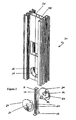
- Figure 2 is an exploded view of the adjustment device and stud of Figure 1, showing components;
- Figure 3 is an exploded, perspective view of a second embodiment of the adjustment device of the invention, the stud being the same as in Figures 1 and 2;
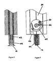
- Figure 4 is a perspective view of a third embodiment of the adjustment device of the invention, inserted in a similar stud to that in the previous Figures and showing the device in the prestressed state;
- Figure 5 is a perspective view of the embodiment of Figure 4, with the stud in an elevated position and the device unstressed;
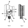
- Figure 6 shows in front elevation the adjustment device and lower part of the stud of Figure 4;
- Figure 7 is a side elevation of the stud and device of Figure 6;
- Figure 8 is a front elevation of the adjustment device and lower part of the stud of Figure 6, with the stud in an elevated position and the device unstressed;
- Figure 9 is a side elevation of the stud and device of Figure 8;
- Figure 10 shows the adjustment device of Figure 6 without the stud;
- Figure 11 is a side elevation of the adjustment device shown in Figure 10;
- Figure 12 is a perspective view of the device of Figures 10 and 11;
- Figure 13 shows, in perspective view, the stud in Figures 1 to 3, without cutouts, and also an embodiment of a joining clip for the stud;
- Figure 14 shows the stud and joining clip of Figure 13, together with the panel also present in Figure 13, all joined together,
- Figure 15 is a cross-sectional view of a second embodiment of the stud;
- Figure 16 is a perspective view of a third embodiment of the building element, being a mullion, having two webs and first, second and third arms; and
- Figure 17 is a similar embodiment to that of Figure 16, but having first, second, third and fourth arms.
- Referring first to Figures 1 and 2,
adjustment device 10 is shown withbase 12 supportingpin 14 which is upstanding frombase 12.Pin 14 has a plurality ofgrooves 16, which in this case spiral aroundpin 14 in the form of a screw.Pin 14 also has end stop 18 (refer Figure 2) at the top ofpin 14. -
Rotatable cam element 20 is adapted to be mounted onpin 14 and has internal protrusions (not shown) which are capable of engaginggrooves 16 whencam element 20 is rotated Rotation ofcam element 20 in one direction will cause it to climb uppin 14, while rotation in the reverse direction will causecam element 20 to descendpin 14. -
Cam element 20 hashexagonal opening 22 for insertion of an allan key (not shown) or similar tool to facilitate rotation ofcam element 20. -
Cam element 20 is made in two parts, 24 and 26. If it is desired to lockcam element 20 onpin 14, this can be achieved via screws 28. -
Stud 30 hasdual webs Adjustment device 10 is designed to fit intoapertures webs - As will be readily appreciated by one skilled in the art, rotation of
cam element 20 onpin 14 will raise orlower stud 30 in relation tobase 12, thus adjusting the height ofstud 30 in situ as desired. - In the case of the second embodiment in Figure 3, like parts are labelled with like numbers. In the second embodiment, however, pin 14, instead of having spiral screw
grooves 16, is flat sided and has inclinedgrooves 42 on either side. - In this Figure,
internal protrusion 40 oncam element 24 is shown. It is this protrusion which engages withinclined grooves 42 whencam element 20 is rotated. - Reference is now made to Figures 4 to 12. Like parts are numbered the same as in Figures 1 to 3.
Adjustment device 10 differs to that in Figure 3 in that it includesspring 44.Spring 44 is attached, at its upper end, tostud 30 byclip 46. The lower end ofspring 44 rests onbase 12.Spring 44 biases cam element 20 (and hence stud 30) away frombase 12. - In the configuration shown in Figure 4,
spring 44 has been compressed and is held in that position by engagement of one ofgrooves 42 by protrusion 40 (not visible in these Figures, but refer Figure 3). When an allen key or other suitable tool (not shown) is inserted inhexagonal opening 22, and rotated,protrusion 40 engages agroove 42, causingcam element 20 and hencestud 30 to change in distance frombase 12. Ifcam element 20 is rotated in the direction shown byarrow 48, the distance increases. Reverse rotation decreases the distance. - In this embodiment, an internal stop 51 (refer Figure 12) (indicated externally by rivet 50) limits rotation in the direction of
arrow 48 beyond about 80°. If at this stage further adjustment is required, rotation ofcam element 20 in the direction opposite to that ofarrow 48 will enableprotrusion 40 to clear allgrooves 42 andpin 14 is released from engagement withcam element 20.Spring 44causes cam element 20 andstud 30 to elevate to the maximum allowable (determined by any horizontal surface abovestud 30 and/or the length ofspring 44 when unstressed). Rotation ofcam element 20 in the direction ofarrow 48 then causesprotrusion 40 to engage agroove 42, to securestud 30 in the desired position, under tension. - So that
cam element 20 may be released from engagement withgrooves 42 inpin 14, protrusion 40 (Figure 3) is deliberately formed so as to leave agap 41 withincam element 20.Gap 41 is sized to allowpin 14 to pass throughcam element 20 whenprotrusion 40 is not in engagement with agroove 42. - It is to be understood that, in any of the embodiments described,
parts cam element 20 may be attached one to the other in any suitable way, including by pop riveting. - Referring next to Figures 13 and 14,
stud 110 haschannels 112 arranged in two sets of three. Eachchannel 112 has a base, 113. Each set ofchannels 112 is separated from the other byparallel webs ribs 140. - Joining clip 116 is made of two parts,
clip carrier 115 andclip 117.Clip carrier 115 is adapted to be attached by a screw or nail inserted betweenparts groove 131 intopanel 118.Parts clip carrier 115 are adapted to push or slide into C-shaped channel 119 onclip 117. -
Clip 117 has co-operating means comprisingresilient arms 114a and 114b which can be forward fitted into one ofchannels 112.Arms 114a and 114b carry grooves or serrations 126 which can lock intocorresponding grooves 130 in the side walls ofchannel 112. -
Stud 110 includesfurther grooves 132 to reduce mass as well asscrew locating grooves 134. - The walls of
channels 112 may be bifurcated to includelarge grooves 142 to assist in reducing mass. - As already indicated, it is contemplated that
clip carrier 115 will be attached topanel 118 at the factory, transported to the site and there mated withclip 117 which in turn is then fitted intochannel 112 ofstud 110. - Turning now to Figure 15,
stud 150 is similar tostud 110 and more clearly illustrates grooves 130,132 and 142. It will be noted, however, thatstud 150 omits reinforcingribs 140. Otherwise,stud 150 is very similar tostud 110. - In Figures 16 and Figure 17, it can be seen that each arm of building
element 190 is joined to a corresponding arm bywebs - The adjustment device of the invention provides a convenient and efficient means to adjust the height of an element. It has ready application in the building industry, where it can provide adjustment for shortcomings in alignment or manufacture of studs, for example. It can enable the use of studs, for example, with a significant difference in height, in the same location. It can be used to level furniture and appliances, inter alia.
Claims (7)
- An adjustment device (10) which includes:a base (12);a pin (14) upstanding from the base (10) and being supported by the base (12), the pin (14) having a plurality of grooves (16,42); anda rotatable cam element (20,24) having a projection (40) capable of engaging one or more of the grooves (16,42) to alter the distance between the base (12) and the cam element (20,24);characterised in that the cam element (20,24) is adapted to be rotated to a position (41) where the projection (40) engages none of the grooves (16,42), and the pin (14) can pass freely through the cam element (20,24), when projection (40) is not in engagement with groove (42).
- The device (10) of claim 1, which further includes means (44) for biasing the cam element (20) with respect to the base (12).
- The device (10) of claim 2, wherein the biasing means (44) includes a spring (44) which biases the cam element (20) away from the base (12).
- The device (10) of any of one of claims 1 to 3, wherein the grooves (42) are inclined.
- The device (10) of claim 4, wherein the grooves (16) form a screw thread.
- The device (10) of claim 4, wherein the grooves (42) are parallel, the pin (14) has opposing sides and the one set of grooves (42) is located on one of the sides of the pin (14) and a second set of grooves (42) is located on the opposing side of the pin (14).
- The device (10) of any one of claims 1 to 6, wherein the cam element (20,24) includes an aperture (22) adapted to receive a tool to facilitate rotation of the cam element (20).
Applications Claiming Priority (5)
| Application Number | Priority Date | Filing Date | Title |
|---|---|---|---|
| AUPR554101 | 2001-06-07 | ||
| AUPR5541A AUPR554101A0 (en) | 2001-06-07 | 2001-06-07 | Improved building elements |
| AUPR554001 | 2001-06-07 | ||
| AUPR5540A AUPR554001A0 (en) | 2001-06-07 | 2001-06-07 | Adjustment device |
| PCT/AU2002/000747 WO2002099214A1 (en) | 2001-06-07 | 2002-06-07 | Adjustment device and building element |
Publications (3)
| Publication Number | Publication Date |
|---|---|
| EP1404929A1 EP1404929A1 (en) | 2004-04-07 |
| EP1404929A4 EP1404929A4 (en) | 2006-05-03 |
| EP1404929B1 true EP1404929B1 (en) | 2007-08-29 |
Family
ID=25646722
Family Applications (1)
| Application Number | Title | Priority Date | Filing Date |
|---|---|---|---|
| EP02737658A Expired - Lifetime EP1404929B1 (en) | 2001-06-07 | 2002-06-07 | Adjustment device and building element |
Country Status (8)
| Country | Link |
|---|---|
| US (1) | US7168213B2 (en) |
| EP (1) | EP1404929B1 (en) |
| JP (2) | JP4121946B2 (en) |
| AT (1) | ATE371778T1 (en) |
| AU (1) | AU2010249242A1 (en) |
| CA (1) | CA2449956C (en) |
| DE (1) | DE60222132T2 (en) |
| WO (1) | WO2002099214A1 (en) |
Cited By (1)
| Publication number | Priority date | Publication date | Assignee | Title |
|---|---|---|---|---|
| IT202400008491A1 (en) * | 2024-04-15 | 2025-10-15 | Tecno Spa | EXTENDABLE POST, FURNITURE ELEMENT |
Families Citing this family (52)
| Publication number | Priority date | Publication date | Assignee | Title |
|---|---|---|---|---|
| US20060101744A1 (en) * | 2004-03-30 | 2006-05-18 | Falbaum Rand H | Ceiling and wall panel clips |
| US20070039258A1 (en) * | 2005-08-19 | 2007-02-22 | Walker John R Iii | Adjustable attachment system |
| US7987644B2 (en) | 2006-09-15 | 2011-08-02 | Enclos Corporation | Curtainwall system |
| US7832154B2 (en) * | 2006-09-18 | 2010-11-16 | Geoff Gosling | Position retention mechanism for modular wall assembly |
| WO2008067287A2 (en) * | 2006-11-27 | 2008-06-05 | Telezygology, Inc. | Adjuster foot |
| US7661237B2 (en) * | 2006-12-11 | 2010-02-16 | Haworth, Ltd. | Skin attachment structure for wall system |
| JP4781287B2 (en) * | 2007-01-25 | 2011-09-28 | 三洋電機株式会社 | Electric washing machine |
| US8056289B1 (en) * | 2008-04-17 | 2011-11-15 | Konvin Associates Ltd. | Dual glazing panel system |
| US9151056B2 (en) * | 2008-04-17 | 2015-10-06 | Konvin Associates, L.P. | Dual glazing panel system |
| JP4944937B2 (en) * | 2008-12-25 | 2012-06-06 | 株式会社大気社 | Building assembly structure and building assembly method using the assembly structure |
| US20100257812A1 (en) * | 2009-04-13 | 2010-10-14 | Schultz Christopher A | Adjustable Attachment System |
| US8382219B2 (en) * | 2009-05-11 | 2013-02-26 | Sub-Zero, Inc. | Installation system and door positioning device for appliances |
| US8209917B1 (en) * | 2009-05-14 | 2012-07-03 | DeZaio Productions, Inc. | Temporary, non-load bearing wall assembly |
| IT1396273B1 (en) * | 2009-10-20 | 2012-11-16 | Sapa Profili S R L | MAST FOR ACOUSTIC BARRIERS AND RELATIVE ACOUSTIC BARRIER. |
| US8528283B2 (en) * | 2010-02-24 | 2013-09-10 | 3Form, Inc. | Pivoting wedge panel mounting assemblies and systems |
| KR100984339B1 (en) * | 2010-05-04 | 2010-09-30 | 나태용 | Variable geometry curtain wall fastner |
| CA2816346C (en) * | 2010-06-04 | 2018-06-12 | Milgard Manufacturing Incorporated | Window mull system |
| WO2012050554A1 (en) | 2010-10-11 | 2012-04-19 | Ig Creative Solutions, Inc. | Housing construction system |
| KR200467593Y1 (en) | 2011-02-24 | 2013-06-20 | 이영미 | Heihgt adjustable support for table |
| AT512642B1 (en) * | 2012-04-19 | 2013-10-15 | Jan Werner | Flexible wall system |
| ITVI20120269A1 (en) | 2012-10-15 | 2014-04-16 | Gemino S R L | CONNECTION STRUCTURE FOR DIVIDING WALLS |
| US10501929B2 (en) | 2013-09-30 | 2019-12-10 | Drew P. HENRY | Hollow connector sleeve with interlocking components |
| US20150135615A1 (en) | 2013-11-08 | 2015-05-21 | Cupples International Inc. | Perimeter wall |
| CA2857149C (en) * | 2014-07-21 | 2021-02-16 | Mike Svenson | Post for a folding door |
| CN105604244B (en) * | 2016-03-09 | 2018-12-11 | 西安建筑科技大学 | A kind of antidetonation steel column with runback bit function |
| KR101705134B1 (en) * | 2016-05-26 | 2017-02-09 | 이청종 | Prefabricated Walls for Interior and Mounting Method thereof |
| CN106013527B (en) * | 2016-05-31 | 2020-03-10 | 陈烁 | Toilet partition board mounting fastener |
| US10260240B1 (en) * | 2017-04-17 | 2019-04-16 | Henry H. Bilge | System for mounting wall panels to a wall |
| US10407917B1 (en) | 2017-04-17 | 2019-09-10 | Henry H. Bilge | System for mounting wall panels to a wall |
| US10787817B1 (en) | 2017-04-17 | 2020-09-29 | Henry H. Bilge | System for mounting adjustable covering panels to a wall |
| US10253507B1 (en) | 2017-04-17 | 2019-04-09 | Henry H. Bilge | System for mounting wall panels to a wall |
| US11111679B2 (en) | 2017-08-15 | 2021-09-07 | National Nail Corp. | Hidden fastener unit and related method of use |
| US11149445B2 (en) | 2017-08-15 | 2021-10-19 | National Nail Corp. | Hidden fastener unit and related method of use |
| USD945870S1 (en) | 2020-11-17 | 2022-03-15 | National Nail Corp. | Fastener positioning device |
| USD850897S1 (en) | 2018-05-18 | 2019-06-11 | National Nail Corp. | Fastener positioning device |
| USD924044S1 (en) | 2019-11-20 | 2021-07-06 | National Nail Corp. | Fastener positioning device |
| USD1019365S1 (en) | 2023-05-31 | 2024-03-26 | National Nail Corp. | Fastener positioning device |
| US11898357B2 (en) | 2017-08-15 | 2024-02-13 | National Nail Corp. | Hidden fastener unit and related method of use |
| USD853829S1 (en) | 2018-06-01 | 2019-07-16 | National Nail Corp. | Fastener positioning device |
| US11261893B2 (en) | 2017-08-15 | 2022-03-01 | National Nail Corp. | Hidden fastener unit and related method of use |
| US12234654B2 (en) | 2017-08-15 | 2025-02-25 | National Nail Corp. | Hidden fastener unit and related method of use |
| US10378218B2 (en) | 2017-08-15 | 2019-08-13 | National Nail Corp. | Hidden fastener unit and related method of use |
| USD1138705S1 (en) | 2018-05-18 | 2026-08-04 | National Nail Corp. | Fastener positioning device |
| US10689845B1 (en) * | 2018-05-25 | 2020-06-23 | Henry H. Bilge | Wall system |
| US11549534B2 (en) * | 2018-12-19 | 2023-01-10 | Jeld-Wen, Inc. | Rotary fastener for securing a fenestration panel |
| USD850898S1 (en) | 2019-01-07 | 2019-06-11 | National Nail Corp. | Fastener positioning device |
| CN111021894B (en) * | 2019-11-13 | 2021-09-07 | 陕西迈拓克能源科技有限公司 | A calibrating device for kitchen door plant |
| US11731252B2 (en) | 2021-01-29 | 2023-08-22 | National Nail Corp. | Screw guide and related method of use |
| US12297649B2 (en) | 2022-10-27 | 2025-05-13 | Primesource Building Products, Inc. | Deck clip |
| USD1022684S1 (en) | 2023-02-23 | 2024-04-16 | National Nail Corp. | Fastener positioning device |
| US12590755B2 (en) | 2024-05-30 | 2026-03-31 | Haier Us Appliance Solutions, Inc. | Mullion guide element for a refrigerator appliance |
| WO2026093776A1 (en) * | 2024-10-28 | 2026-05-07 | El Rifai Walid Abdul Wahab | Universal construction profiles system |
Family Cites Families (71)
| Publication number | Priority date | Publication date | Assignee | Title |
|---|---|---|---|---|
| DE323158C (en) * | 1920-07-16 | Heinrich F A Luebbe | Screw jack | |
| US2103202A (en) * | 1933-10-24 | 1937-12-21 | Automatic Instr Company | Leg adjuster |
| US3053353A (en) * | 1958-01-23 | 1962-09-11 | Miller Ind Inc | Frame for curtain wall construction |
| GB843571A (en) * | 1958-04-02 | 1960-08-04 | Rowe Ind Kirby Ltd | Improvements in or relating to partitions for dividing up offices and other rooms |
| CH374471A (en) | 1959-02-12 | 1964-01-15 | Koller Ernst | Posts for walls, in particular partitions in buildings |
| US3134404A (en) * | 1961-02-27 | 1964-05-26 | William B Jaspert | Electro-magnetically operated floating armature valves |
| GB974551A (en) * | 1962-06-16 | |||
| NL6809848A (en) * | 1968-04-19 | 1969-10-21 | ||
| AU5587769A (en) | 1969-06-02 | 1970-12-10 | Ernst Lust Kg | Partition wall |
| US3760547A (en) * | 1969-08-13 | 1973-09-25 | J Brenneman | Spline and seat connector assemblies |
| US3596958A (en) * | 1969-08-27 | 1971-08-03 | William R Bowerman | Magnetic lock |
| US3686810A (en) * | 1970-11-05 | 1972-08-29 | Charles R Allen | Snap on drywall fastening system |
| US3844086A (en) * | 1972-08-14 | 1974-10-29 | Paper Corp | Method of assembling skylight structures |
| US3866374A (en) * | 1972-10-05 | 1975-02-18 | Standard Products Co | Panel mounting system |
| US3866364A (en) * | 1973-05-10 | 1975-02-18 | Int Product Dev Inc | Modular structure for use in merchandising operations |
| FR2240327A1 (en) * | 1973-08-09 | 1975-03-07 | Schlumberger Compteurs | Demountable panel type partition - panel edges are clamped by flanged clip concealed by outer strip |
| JPS5053920U (en) * | 1973-09-11 | 1975-05-23 | ||
| US3877191A (en) * | 1974-05-07 | 1975-04-15 | Westinghouse Electric Corp | Connector assembly and support post |
| GB1503588A (en) * | 1975-07-03 | 1978-03-15 | Profiles & Tubes De L Est | Building frame structural elements and fixing members therefor |
| JPS557614Y2 (en) * | 1975-07-14 | 1980-02-20 | ||
| NZ184154A (en) | 1976-01-15 | 1979-03-16 | Jones Bd | Capped hollow connector sleeves mounted on a post |
| FR2449174A1 (en) | 1979-02-19 | 1980-09-12 | Modal | Demountable glazed partition wall - has frame section with four connected vertical webs with flanges giving one and three channels per face |
| NL190790C (en) | 1980-04-15 | 1994-08-16 | Pella Bv | Folding wall. |
| FR2484501A1 (en) | 1980-06-13 | 1981-12-18 | Michelet Marceau | Double wall removable partition - contains cavity for insulation and is installed using three different metallic components |
| US4388786A (en) * | 1981-01-30 | 1983-06-21 | Kurt Gassler | Construction means for use in the assembly of wall and/or roof structures |
| GB2107754B (en) | 1981-09-18 | 1985-03-13 | Marley Haley Exposystems Limit | Posts barriers personnel guidance systems gates |
| AU549805B2 (en) * | 1981-11-02 | 1986-02-13 | Gkn Kwikform Ltd. | Beam |
| GB2131869B (en) | 1982-12-10 | 1986-10-22 | Energy Equip | Lock |
| DE3342169C2 (en) * | 1983-11-22 | 2001-03-08 | Reinhard Hertel | table |
| FR2578622A2 (en) * | 1984-05-18 | 1986-09-12 | Rothschild Philippe | EXTENSIBLE SUPPORT DEVICE WITH EFFECTIVE SUPPORT SYSTEM AT EACH BEARING |
| JPS611512U (en) * | 1984-06-11 | 1986-01-08 | ワイケイケイ株式会社 | Watertight device between units |
| JPS6182016A (en) * | 1984-09-14 | 1986-04-25 | Honda Motor Co Ltd | Connecting rod of reciprocating engine |
| CA1328474C (en) * | 1985-11-07 | 1994-04-12 | Roger Conington Richards | Magnetically operated latch |
| US4667916A (en) * | 1985-12-20 | 1987-05-26 | Richards Peter S | Overhead hanger and joint construction |
| DE3613574A1 (en) | 1986-04-22 | 1987-12-23 | Theodor Puschkarski | CONNECTING ELEMENT TO CONNECT TWO PANELS |
| IT1197845B (en) * | 1986-08-05 | 1988-12-06 | Riri Italia Spa | PAVILION REMOVABLE PARTICULARLY FOR THE TEMPORARY RECOVERY OF PEOPLE |
| US4802296A (en) | 1986-12-30 | 1989-02-07 | Signcomp, Inc. | Architectural sign system |
| IT1230005B (en) * | 1989-04-21 | 1991-09-20 | Giovannetti F | LOWERING LIFTING DEVICE, PARTICULARLY FOR LEVEL ADJUSTMENT. |
| NZ235365A (en) * | 1989-09-18 | 1993-08-26 | Logan Units Australia Pty Ltd | Stud and keying element |
| SE467882B (en) | 1989-11-24 | 1992-09-28 | Silentia Ab | DEVICE ON SHIELD WALL |
| US5042555A (en) * | 1990-10-01 | 1991-08-27 | Modernfold, Inc. | Floor-supported movable wall panel with height adjustment system |
| US5170801A (en) * | 1990-10-02 | 1992-12-15 | Glaxo Inc. | Medical capsule device actuated by radio-frequency (rf) signal |
| JPH0810610Y2 (en) * | 1990-10-19 | 1996-03-29 | 株式会社岡村製作所 | Panel mounting device |
| FR2679939A1 (en) * | 1991-07-29 | 1993-02-05 | Matfor | One-piece panel for a removable partition having recessed or flat joints, corresponding partition and method of laying it |
| US5481839A (en) * | 1992-09-09 | 1996-01-09 | Kawneer Company, Inc. | Glazed panel wall construction and method for assembly thereof |
| IT1256180B (en) * | 1992-12-01 | 1995-11-29 | Edoardo Zanoni | COMPLEX OF METAL PROFILES SUITABLE FOR CONSTRUCTION OF MOVABLE WALLS AND RELATIVE MOVABLE WALL. |
| NL9300232A (en) | 1993-02-04 | 1994-09-01 | Pella Bv | Flat-folding wall. |
| US5439310A (en) * | 1993-05-25 | 1995-08-08 | The United States Of America As Represented By United States National Aeronautics And Space Administration | Connector systems for structures |
| US5490648A (en) * | 1993-06-07 | 1996-02-13 | Cullen; Christopher P. | Mechanical stabilizer |
| US5466083A (en) * | 1993-10-12 | 1995-11-14 | Hogg; John M. | Electrically operated motorized turnbuckle |
| US5452557A (en) * | 1993-11-12 | 1995-09-26 | Alumber Llc | Aluminum framing |
| US5634300A (en) * | 1994-03-10 | 1997-06-03 | Plascore Inc. | Wall system employing grooved posts, connector blocks and T-bolt receiving battens |
| JPH07268990A (en) * | 1994-03-30 | 1995-10-17 | Kokuyo Co Ltd | Panel fixing structure |
| FR2718510B3 (en) * | 1994-04-06 | 1996-08-30 | Raymond Mamane | Method and device for assembling profiles, and structure which can be dismantled by application. |
| FR2721053B1 (en) * | 1994-06-10 | 1996-08-02 | Fabrication Diffusion | Installation installation of panels without visible fixing, in particular for the covering of walls and / or the installation of shelves or suspended equipment and tool for the installation of such an installation. |
| US5644878A (en) * | 1995-01-11 | 1997-07-08 | Sony Corporation | Reusable finish trim for prefabricated clean room wall system |
| NL9500419A (en) | 1995-03-03 | 1996-10-01 | Anton Tapper | Assembly comprising a panel and a profile, as well as a spring element, panel, profile and form strip suitable for use in such an assembly. |
| GB2300867B (en) * | 1995-05-15 | 1998-07-29 | Chingdar Enterprise Co Limited | Partition wall |
| FR2753733B1 (en) * | 1996-09-20 | 1998-11-27 | DEVICE FOR MOUNTING AND IMMOBILIZING A HOLLOW SUPPORT POST FOR INTERIOR PARTITION OF A PREMISES | |
| AUPO291296A0 (en) * | 1996-10-11 | 1996-11-07 | Rudduck, Dickory | Building elements |
| DE29618340U1 (en) | 1996-10-22 | 1997-02-13 | LIENHOP Planen Zelte Textiles Bauen GmbH, 28197 Bremen | Frame element with flexible covering and structure made of such frame elements |
| GB2322646B (en) * | 1997-03-01 | 2001-09-12 | Komfort Systems Ltd | Partitioning system |
| TW349560U (en) * | 1998-02-21 | 1999-01-01 | yi-cheng Xue | Improvement for material of partitioned wall |
| US6003279A (en) * | 1998-08-13 | 1999-12-21 | Schneider; Dale P. | Sunroom enclosure |
| US6023896A (en) * | 1998-08-24 | 2000-02-15 | Finish Group Ltd. | Modular partition systems and methods for assembling such systems |
| GB9824841D0 (en) * | 1998-11-13 | 1999-01-06 | Coseley Panel Products Limited | A cladding system |
| ATE260438T1 (en) * | 1998-12-22 | 2004-03-15 | Ultraframe Uk Ltd | FRAME CONSTRUCTION PART |
| EP1022403A1 (en) * | 1999-01-21 | 2000-07-26 | Hoyez Sa | Removable acoustical partition wall |
| WO2001016013A1 (en) * | 1999-09-01 | 2001-03-08 | E. A. Storz Gmbh & Co. Kg | Jack |
| US6247282B1 (en) * | 1999-10-28 | 2001-06-19 | Icon, Incorporated | Deck and beam connector |
| USD465035S1 (en) * | 2001-12-04 | 2002-10-29 | Mcfarland Daniel J. | Frame profile |
-
2002
- 2002-06-07 CA CA002449956A patent/CA2449956C/en not_active Expired - Fee Related
- 2002-06-07 AT AT02737658T patent/ATE371778T1/en not_active IP Right Cessation
- 2002-06-07 DE DE60222132T patent/DE60222132T2/en not_active Expired - Lifetime
- 2002-06-07 JP JP2003502310A patent/JP4121946B2/en not_active Expired - Fee Related
- 2002-06-07 WO PCT/AU2002/000747 patent/WO2002099214A1/en not_active Ceased
- 2002-06-07 EP EP02737658A patent/EP1404929B1/en not_active Expired - Lifetime
-
2003
- 2003-12-05 US US10/727,987 patent/US7168213B2/en not_active Expired - Fee Related
-
2008
- 2008-02-05 JP JP2008024724A patent/JP2008111336A/en active Pending
-
2010
- 2010-12-13 AU AU2010249242A patent/AU2010249242A1/en not_active Abandoned
Cited By (1)
| Publication number | Priority date | Publication date | Assignee | Title |
|---|---|---|---|---|
| IT202400008491A1 (en) * | 2024-04-15 | 2025-10-15 | Tecno Spa | EXTENDABLE POST, FURNITURE ELEMENT |
Also Published As
| Publication number | Publication date |
|---|---|
| CA2449956A1 (en) | 2002-12-12 |
| US20040168382A1 (en) | 2004-09-02 |
| ATE371778T1 (en) | 2007-09-15 |
| US7168213B2 (en) | 2007-01-30 |
| CA2449956C (en) | 2009-06-02 |
| JP2004521212A (en) | 2004-07-15 |
| HK1065083A1 (en) | 2005-02-08 |
| EP1404929A1 (en) | 2004-04-07 |
| DE60222132D1 (en) | 2007-10-11 |
| DE60222132T2 (en) | 2008-05-15 |
| JP2008111336A (en) | 2008-05-15 |
| EP1404929A4 (en) | 2006-05-03 |
| JP4121946B2 (en) | 2008-07-23 |
| WO2002099214A1 (en) | 2002-12-12 |
| AU2010249242A1 (en) | 2011-01-06 |
Similar Documents
| Publication | Publication Date | Title |
|---|---|---|
| US7168213B2 (en) | Adjustment device and building element | |
| US20180299106A1 (en) | Bar hanger with identical members for recessed luminaires | |
| US20060243877A1 (en) | Hanger bar centering mechanism | |
| US20100252552A1 (en) | Adjustable Depth Electrical Components | |
| CA3030664A1 (en) | Device for fastening a panel-shaped component in a receiving groove of a carrying rail | |
| US11454021B2 (en) | Locking assembly for securing one or more building elements in a building system | |
| WO2011088622A1 (en) | A tiltable flat panel display mount | |
| US7909530B2 (en) | Connection hardware for wooden building | |
| HK1065083B (en) | Adjustment device and building element | |
| AU2002312646B2 (en) | Adjustment device and building element | |
| KR101969058B1 (en) | Assembling apparatus for temporary structure | |
| AU2002312646A1 (en) | Adjustment device and building element | |
| JP2020023786A (en) | Interior wall panel unit | |
| US11406184B2 (en) | Snap lock system, method and use for connecting construction elements | |
| JP6738199B2 (en) | Panel connection structure | |
| US20080289380A1 (en) | Pin Assembly | |
| AU2021366181A1 (en) | Panel connection system | |
| KR102570493B1 (en) | Pipe Connection Structure | |
| JPS645293Y2 (en) | ||
| GB2138862A (en) | An assembly for supporting a suspended ceiling and a ceiling suspended thereby | |
| JP4905418B2 (en) | Panel coupling device in stacked partition device | |
| JP2005180043A (en) | Metal fittings for wooden building components | |
| CN121575852A (en) | A prefabricated beam-column external movable clamp and its manufacturing and usage method | |
| JPH0734977Y2 (en) | Mounting hardware on top of wall panel | |
| JPH0738506Y2 (en) | Panel mounting structure |
Legal Events
| Date | Code | Title | Description |
|---|---|---|---|
| PUAI | Public reference made under article 153(3) epc to a published international application that has entered the european phase |
Free format text: ORIGINAL CODE: 0009012 |
|
| 17P | Request for examination filed |
Effective date: 20031230 |
|
| AK | Designated contracting states |
Kind code of ref document: A1 Designated state(s): AT BE CH CY DE DK ES FI FR GB GR IE IT LI LU MC NL PT SE TR |
|
| AX | Request for extension of the european patent |
Extension state: AL LT LV MK RO SI |
|
| REG | Reference to a national code |
Ref country code: HK Ref legal event code: DE Ref document number: 1065083 Country of ref document: HK |
|
| A4 | Supplementary search report drawn up and despatched |
Effective date: 20060321 |
|
| 17Q | First examination report despatched |
Effective date: 20060728 |
|
| GRAP | Despatch of communication of intention to grant a patent |
Free format text: ORIGINAL CODE: EPIDOSNIGR1 |
|
| GRAS | Grant fee paid |
Free format text: ORIGINAL CODE: EPIDOSNIGR3 |
|
| GRAA | (expected) grant |
Free format text: ORIGINAL CODE: 0009210 |
|
| AK | Designated contracting states |
Kind code of ref document: B1 Designated state(s): AT BE CH CY DE DK ES FI FR GB GR IE IT LI LU MC NL PT SE TR |
|
| REG | Reference to a national code |
Ref country code: GB Ref legal event code: FG4D |
|
| REG | Reference to a national code |
Ref country code: CH Ref legal event code: EP |
|
| REG | Reference to a national code |
Ref country code: IE Ref legal event code: FG4D |
|
| REF | Corresponds to: |
Ref document number: 60222132 Country of ref document: DE Date of ref document: 20071011 Kind code of ref document: P |
|
| REG | Reference to a national code |
Ref country code: HK Ref legal event code: GR Ref document number: 1065083 Country of ref document: HK |
|
| PG25 | Lapsed in a contracting state [announced via postgrant information from national office to epo] |
Ref country code: NL Free format text: LAPSE BECAUSE OF FAILURE TO SUBMIT A TRANSLATION OF THE DESCRIPTION OR TO PAY THE FEE WITHIN THE PRESCRIBED TIME-LIMIT Effective date: 20070829 Ref country code: FI Free format text: LAPSE BECAUSE OF FAILURE TO SUBMIT A TRANSLATION OF THE DESCRIPTION OR TO PAY THE FEE WITHIN THE PRESCRIBED TIME-LIMIT Effective date: 20070829 Ref country code: ES Free format text: LAPSE BECAUSE OF FAILURE TO SUBMIT A TRANSLATION OF THE DESCRIPTION OR TO PAY THE FEE WITHIN THE PRESCRIBED TIME-LIMIT Effective date: 20071210 |
|
| NLV1 | Nl: lapsed or annulled due to failure to fulfill the requirements of art. 29p and 29m of the patents act | ||
| PG25 | Lapsed in a contracting state [announced via postgrant information from national office to epo] |
Ref country code: LI Free format text: LAPSE BECAUSE OF FAILURE TO SUBMIT A TRANSLATION OF THE DESCRIPTION OR TO PAY THE FEE WITHIN THE PRESCRIBED TIME-LIMIT Effective date: 20070829 Ref country code: AT Free format text: LAPSE BECAUSE OF FAILURE TO SUBMIT A TRANSLATION OF THE DESCRIPTION OR TO PAY THE FEE WITHIN THE PRESCRIBED TIME-LIMIT Effective date: 20070829 Ref country code: CH Free format text: LAPSE BECAUSE OF FAILURE TO SUBMIT A TRANSLATION OF THE DESCRIPTION OR TO PAY THE FEE WITHIN THE PRESCRIBED TIME-LIMIT Effective date: 20070829 |
|
| REG | Reference to a national code |
Ref country code: CH Ref legal event code: PL |
|
| PG25 | Lapsed in a contracting state [announced via postgrant information from national office to epo] |
Ref country code: BE Free format text: LAPSE BECAUSE OF FAILURE TO SUBMIT A TRANSLATION OF THE DESCRIPTION OR TO PAY THE FEE WITHIN THE PRESCRIBED TIME-LIMIT Effective date: 20070829 |
|
| ET | Fr: translation filed | ||
| PG25 | Lapsed in a contracting state [announced via postgrant information from national office to epo] |
Ref country code: GR Free format text: LAPSE BECAUSE OF FAILURE TO SUBMIT A TRANSLATION OF THE DESCRIPTION OR TO PAY THE FEE WITHIN THE PRESCRIBED TIME-LIMIT Effective date: 20071130 Ref country code: DK Free format text: LAPSE BECAUSE OF FAILURE TO SUBMIT A TRANSLATION OF THE DESCRIPTION OR TO PAY THE FEE WITHIN THE PRESCRIBED TIME-LIMIT Effective date: 20070829 |
|
| PG25 | Lapsed in a contracting state [announced via postgrant information from national office to epo] |
Ref country code: PT Free format text: LAPSE BECAUSE OF FAILURE TO SUBMIT A TRANSLATION OF THE DESCRIPTION OR TO PAY THE FEE WITHIN THE PRESCRIBED TIME-LIMIT Effective date: 20080129 |
|
| PG25 | Lapsed in a contracting state [announced via postgrant information from national office to epo] |
Ref country code: SE Free format text: LAPSE BECAUSE OF FAILURE TO SUBMIT A TRANSLATION OF THE DESCRIPTION OR TO PAY THE FEE WITHIN THE PRESCRIBED TIME-LIMIT Effective date: 20071129 |
|
| PLBE | No opposition filed within time limit |
Free format text: ORIGINAL CODE: 0009261 |
|
| STAA | Information on the status of an ep patent application or granted ep patent |
Free format text: STATUS: NO OPPOSITION FILED WITHIN TIME LIMIT |
|
| 26N | No opposition filed |
Effective date: 20080530 |
|
| PG25 | Lapsed in a contracting state [announced via postgrant information from national office to epo] |
Ref country code: MC Free format text: LAPSE BECAUSE OF NON-PAYMENT OF DUE FEES Effective date: 20080630 |
|
| PG25 | Lapsed in a contracting state [announced via postgrant information from national office to epo] |
Ref country code: IE Free format text: LAPSE BECAUSE OF NON-PAYMENT OF DUE FEES Effective date: 20080609 |
|
| PG25 | Lapsed in a contracting state [announced via postgrant information from national office to epo] |
Ref country code: CY Free format text: LAPSE BECAUSE OF FAILURE TO SUBMIT A TRANSLATION OF THE DESCRIPTION OR TO PAY THE FEE WITHIN THE PRESCRIBED TIME-LIMIT Effective date: 20070829 |
|
| PG25 | Lapsed in a contracting state [announced via postgrant information from national office to epo] |
Ref country code: LU Free format text: LAPSE BECAUSE OF NON-PAYMENT OF DUE FEES Effective date: 20080607 |
|
| PG25 | Lapsed in a contracting state [announced via postgrant information from national office to epo] |
Ref country code: TR Free format text: LAPSE BECAUSE OF FAILURE TO SUBMIT A TRANSLATION OF THE DESCRIPTION OR TO PAY THE FEE WITHIN THE PRESCRIBED TIME-LIMIT Effective date: 20070829 |
|
| PGFP | Annual fee paid to national office [announced via postgrant information from national office to epo] |
Ref country code: GB Payment date: 20120629 Year of fee payment: 11 |
|
| PGFP | Annual fee paid to national office [announced via postgrant information from national office to epo] |
Ref country code: IT Payment date: 20120621 Year of fee payment: 11 |
|
| PGFP | Annual fee paid to national office [announced via postgrant information from national office to epo] |
Ref country code: FR Payment date: 20120720 Year of fee payment: 11 Ref country code: DE Payment date: 20120830 Year of fee payment: 11 |
|
| GBPC | Gb: european patent ceased through non-payment of renewal fee |
Effective date: 20130607 |
|
| REG | Reference to a national code |
Ref country code: FR Ref legal event code: ST Effective date: 20140228 |
|
| REG | Reference to a national code |
Ref country code: DE Ref legal event code: R119 Ref document number: 60222132 Country of ref document: DE Effective date: 20140101 |
|
| PG25 | Lapsed in a contracting state [announced via postgrant information from national office to epo] |
Ref country code: GB Free format text: LAPSE BECAUSE OF NON-PAYMENT OF DUE FEES Effective date: 20130607 Ref country code: DE Free format text: LAPSE BECAUSE OF NON-PAYMENT OF DUE FEES Effective date: 20140101 |
|
| PG25 | Lapsed in a contracting state [announced via postgrant information from national office to epo] |
Ref country code: FR Free format text: LAPSE BECAUSE OF NON-PAYMENT OF DUE FEES Effective date: 20130701 Ref country code: IT Free format text: LAPSE BECAUSE OF NON-PAYMENT OF DUE FEES Effective date: 20130607 |