EP1404060A2 - Drahtloses Kommunikationsendgerät - Google Patents
Drahtloses Kommunikationsendgerät Download PDFInfo
- Publication number
- EP1404060A2 EP1404060A2 EP03256149A EP03256149A EP1404060A2 EP 1404060 A2 EP1404060 A2 EP 1404060A2 EP 03256149 A EP03256149 A EP 03256149A EP 03256149 A EP03256149 A EP 03256149A EP 1404060 A2 EP1404060 A2 EP 1404060A2
- Authority
- EP
- European Patent Office
- Prior art keywords
- wireless
- signal
- unit
- transmission
- controller
- Prior art date
- Legal status (The legal status is an assumption and is not a legal conclusion. Google has not performed a legal analysis and makes no representation as to the accuracy of the status listed.)
- Withdrawn
Links
Images







Classifications
-
- H—ELECTRICITY
- H04—ELECTRIC COMMUNICATION TECHNIQUE
- H04B—TRANSMISSION
- H04B1/00—Details of transmission systems, not covered by a single one of groups H04B3/00 - H04B13/00; Details of transmission systems not characterised by the medium used for transmission
- H04B1/0003—Software-defined radio [SDR] systems, i.e. systems wherein components typically implemented in hardware, e.g. filters or modulators/demodulators, are implented using software, e.g. by involving an AD or DA conversion stage such that at least part of the signal processing is performed in the digital domain
-
- H—ELECTRICITY
- H04—ELECTRIC COMMUNICATION TECHNIQUE
- H04M—TELEPHONIC COMMUNICATION
- H04M1/00—Substation equipment, e.g. for use by subscribers
- H04M1/72—Mobile telephones; Cordless telephones, i.e. devices for establishing wireless links to base stations without route selection
- H04M1/724—User interfaces specially adapted for cordless or mobile telephones
- H04M1/72403—User interfaces specially adapted for cordless or mobile telephones with means for local support of applications that increase the functionality
-
- H—ELECTRICITY
- H04—ELECTRIC COMMUNICATION TECHNIQUE
- H04B—TRANSMISSION
- H04B1/00—Details of transmission systems, not covered by a single one of groups H04B3/00 - H04B13/00; Details of transmission systems not characterised by the medium used for transmission
- H04B1/38—Transceivers, i.e. devices in which transmitter and receiver form a structural unit and in which at least one part is used for functions of transmitting and receiving
- H04B1/40—Circuits
- H04B1/403—Circuits using the same oscillator for generating both the transmitter frequency and the receiver local oscillator frequency
- H04B1/406—Circuits using the same oscillator for generating both the transmitter frequency and the receiver local oscillator frequency with more than one transmission mode, e.g. analog and digital modes
-
- H—ELECTRICITY
- H04—ELECTRIC COMMUNICATION TECHNIQUE
- H04W—WIRELESS COMMUNICATION NETWORKS
- H04W88/00—Devices specially adapted for wireless communication networks, e.g. terminals, base stations or access point devices
- H04W88/02—Terminal devices
- H04W88/06—Terminal devices adapted for operation in multiple networks or having at least two operational modes, e.g. multi-mode terminals
-
- H—ELECTRICITY
- H04—ELECTRIC COMMUNICATION TECHNIQUE
- H04M—TELEPHONIC COMMUNICATION
- H04M2250/00—Details of telephonic subscriber devices
- H04M2250/02—Details of telephonic subscriber devices including a Bluetooth® interface
-
- H—ELECTRICITY
- H04—ELECTRIC COMMUNICATION TECHNIQUE
- H04W—WIRELESS COMMUNICATION NETWORKS
- H04W28/00—Network traffic management; Network resource management
- H04W28/16—Central resource management; Negotiation of resources or communication parameters, e.g. negotiating bandwidth or QoS [Quality of Service]
- H04W28/18—Negotiating wireless communication parameters
-
- H—ELECTRICITY
- H04—ELECTRIC COMMUNICATION TECHNIQUE
- H04W—WIRELESS COMMUNICATION NETWORKS
- H04W76/00—Connection management
- H04W76/10—Connection setup
-
- H—ELECTRICITY
- H04—ELECTRIC COMMUNICATION TECHNIQUE
- H04W—WIRELESS COMMUNICATION NETWORKS
- H04W8/00—Network data management
- H04W8/22—Processing or transfer of terminal data, e.g. status or physical capabilities
- H04W8/24—Transfer of terminal data
- H04W8/245—Transfer of terminal data from a network towards a terminal
-
- H—ELECTRICITY
- H04—ELECTRIC COMMUNICATION TECHNIQUE
- H04W—WIRELESS COMMUNICATION NETWORKS
- H04W84/00—Network topologies
- H04W84/02—Hierarchically pre-organised networks, e.g. paging networks, cellular networks, WLAN [Wireless Local Area Network] or WLL [Wireless Local Loop]
- H04W84/04—Large scale networks; Deep hierarchical networks
- H04W84/042—Public Land Mobile systems, e.g. cellular systems
-
- H—ELECTRICITY
- H04—ELECTRIC COMMUNICATION TECHNIQUE
- H04W—WIRELESS COMMUNICATION NETWORKS
- H04W88/00—Devices specially adapted for wireless communication networks, e.g. terminals, base stations or access point devices
- H04W88/02—Terminal devices
Definitions
- a dual mode wireless terminal that can be used for both a cellular phone and PHS (Personal Handy Phone System) has been currently developed and put on the market. This is manufactured by housing two different hardware corresponding to two different wireless systems (i.e. cellular and PHS) in one housing. It was impossible to add another new wireless system, or update existing function already built therein.
- PHS Personal Handy Phone System
- the service providers deliver requested information to users who requested the information beforehand.
- the user who has a wireless communication terminal having a function of mobile phones and a simple wireless equipment like a wireless LAN, sends the request message to the service provider for downloading the information by using the mobile phone get information.
- the user gets the requested information by using the simple wireless equipment.
- a wireless communication terminal comprising:
- a wireless communication terminal comprising:
- a wireless communication terminal comprising:
- a wireless communication terminal comprising:
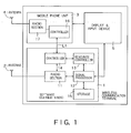
- Fig. 1 is a diagram showing the schematic configuration of a wireless communication terminal according to a first embodiment of the present invention.
- the wireless communication terminal in Fig. 1 comprises a software defined radio 1, an antenna 2 for the software defined radio 1, a mobile phone unit 3, an antenna 2 for the mobile phone unit 3, and a display and input device 5.
- the software defined radio 1 comprises: a radio section 11 for transferring wireless signals; a signal processing unit 12 having a reconfigurable unit in which the content of the signal processing for the wireless signal transferred by the radio section 11 can be changed, and a non-reconfigurable unit in which the content of the signal processing cannot be changed; a resource controller 13 which controls changing of the content of the signal processing in the reconfigurable unit in the signal processing unit 12; a controller 14 for controlling the radio section 11, the signal processing unit 12, and the resource controller 13; and a storage 15 which stores functions implemented in the signal processing unit 12 and the transferred data.
- the mobile phone unit 3 being received the type approval by the official organization, has a ontroller 16 and a radio section 17 therein.
- the wireless communication terminal in Fig. 1 is built into LSI for miniaturization.
- a processor, a memory, and a logic circuit are included in the LSI, and the processor, the memory, and the logic circuit are used to execute a variety of processing such as wireless signal processing, protocol processing, and man-machine interface processing.
- the radio waves received by the antenna 2 of the software defined radio 1 are frequency-converted and digitalized by the radio section 11, and sent out to the signal processing unit 12.
- the signal processing unit 12 executes demodulation processing with respect to the digitalized reception signal from the radio section 11.
- the signal processing unit 12 comprises a digital signal processor (DSP) and a rewritable logic (FPGA), as a specific mounting form.
- DSP digital signal processor
- FPGA rewritable logic
- the resource controller 13 controls setting and changes of the function of the signal processing unit 12. More specifically, the resource controller 13 comprises a resource control table for recording the status of use of resources such as memories, a resource manager, and a resource changing section, and the resource manager monitors the status of use of the resources to update the resource control table.
- a resource control table for recording the status of use of resources such as memories, a resource manager, and a resource changing section, and the resource manager monitors the status of use of the resources to update the resource control table.
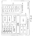
- Fig. 2 is a block diagram showing one example of the internal configuration of the signal processing unit 12.
- the signal processing unit 12 has a reconfigurable unit 21 and a non-reconfigurable unit 22.
- the non-reconfigurable unit 22 comprises: a logic circuit including a CRC adding unit 23, a CRC checking unit 24, a correlator 25, a convolutional encoder 26, a calculator 27, and a Viterbi decoder 28; DSPs 29; and a memory 30.
- the reconfigurable unit 21 has PLDs (Programmable Logic Devices) 31 that can form an arbitrary logic circuit.
- PLDs Programmable Logic Devices
- the control signal includes broadcast information to all of the terminals and the peculiar informative information transmitted to a specific terminal.
- the broadcast information includes information relating to the radio channel structure, information relating to control carrier configuration, system operation information, congestion restriction information, country code, system type, general calling area type, and option information.
- the peculiar informative information transmitted from a base station to a specific terminal includes a channel reestablishing request, channel allocation information, rejection of channel allocation, and an incoming call.
- the broadcast information is informed by a broadcast channel (a so-called B-CH).
- the broadcast information is transmitted by a request from a terminal or from the base station, after having established a link.
- the broadcast information is generally transmitted by using a control message.
- the message format is individually specified according to the respective wireless systems.
- Fig. 3 illustrates one example of formats for a link channel allocation rejection message in the PHS system.
- This message is described in STD-28, which is the Standards of ARIB (Association of Radio Industries and Businesses).
- the message includes a message type 31, and information 32 accompanying the message.
- the message is individually and strictly defined for secret key setting, function request, response to incoming calls, radio channel cutoff, radio channel cutoff completion, radio status report, channel switching instruction, and the like.
- the control information is peculiar to the wireless system. Therefore, when the communication is within a single wireless system, it is not necessary for others to comprehend the control information peculiar to the system.
- the wireless communication terminal using the software defined radio technique can operate an application using a plurality of wireless systems. It is also possible for this wireless commutation terminal to comprehend the control information of the respective systems.
- the zone herein stands for a general calling area and an individual cell coverage.
- the control information is transmitted from the controller 16 via the control line L1 to the controller 14.
- versions can be managed with a time stamp, useful control information can be selected at all times.
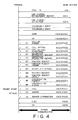
- FIG. 4 shows an example of a control sequence when receiving an incoming call in the PHS.
- the sequence in Fig. 4 is described in STD-28, which is the Standards of ARIB, and hence detailed explanation is omitted. Communication is established through exchanges of these control signals.
- the control information relating to the restriction of transmission will be described.
- a business proprietor who provides a telecommunication service needs to handle important communication by priority.
- the base station can transmit a signal for restricting transmission from general terminals, as required.
- Restriction of transmission is requested, for example, by the fifth and sixth octets in the system information informative message in the PHS, by the fourth to sixth octets in the informative information message in the PDC system, and by PSIST and MSGPSIST in an access parameter message in the CDMA system.
- this restriction message for example, in the case of the PDC system, accesses to general terminals, accesses to priority terminals, accesses to other zones, accesses to own zone, and an access cycle are restricted by the base station.
- Fig. 5 indicates the cell coverage of the wireless communication terminal in Fig. 1.
- the cell coverage 33 for simple wireless equipment configured by software defined radio technique is very narrow as compared with the cell coverage 34 of the mobile phone (cellular), and is referred to as a spot area.
- This kind of spot area is provided, for example, in a train, in the vicinity of ticket gates in stations, and in the vicinity of tollgates of a highway.
- the service provider who provides a variety of information transmits high-speed signals within the spot area, to provide desired information (for example, services of contents distribution and information distribution) to users having the simple wireless equipment.
- the simple wireless equipment is like the wireless LAN equipment, Bluetooth (TM) equipment etc.
- the regulations in Telecommunication Business Law for simple wireless equipments are not strict rather than cellular phones.
- the regulation for type approval for such simple wireless equipment is also not so strict rather than cellular phone.
- the service quality by the information distribution service can be improved, by cooperating with the wireless systems having an extended area, such as the mobile phone.
- the mobile phone is popularized due to the wide service area, though the signal transmission rate is limited to several kbps to several hundreds kbps.
- the services of the mobile phone are developed nationally.
- a user of wireless communication terminal this embodiment declares desired information list beforehand to the provider, by using the mobile phone unit 3, and when the user approaches a spot area, or drops in the spot area, the user obtains the desired information by software defined radio 1.
- the mobile phone 3 by combining the mobile phone 3 and the simple wireless equipment configured by software defined radio technique, requested service can be provided, thereby improving the convenience of the user.
- Fig. 6 shows one example of the wireless communication system using the wireless communication terminal in Fig. 1.
- a server 52 of a service provider who provides services in a spot area 51 is connected to a backbone network 53 by cable.
- This server 52 can perform wireless communication with a base station 54, which communicates with the wireless communication terminal held by a user.
- the user when having reached the spot area, the user can receive the service from the service provider by the simple wireless equipment, and can also receive the similar service outside the spot area, by the mobile phone unit 3.
- the simple wireless equipment used in the spots provided in a plurality of numbers may be of any specification.
- the function of the simple wireless equipment can be arbitrarily determined by the service provider who provides the information distribution service in the spot area.
- the user can receive the service only in the spot area corresponding to the simple wireless equipment possessed by the user, thereby considerably deteriorating the convenience of the user.
- the software defined radio 1 can realize arbitrary simple wireless equipment by conducting wireless signal processing by the DSP or hardware that can easily change the function.
- the wireless communication terminal is constructed by combining the software defined radio 1 and the mobile phone unit 3.
- the business proprietor who provides services for the mobile phone and the information distribution service provider in the spot area are generally separate vendors.
- the information distribution service provider in the spot area ensures a wide area by using the mobile phone to improve the serve quality.
- a mobile phone in order to ensure important communication including an emergency communication, a mobile phone shall have a function by which it stops the origination of a call when it has received a signal from the mobile phone circuit facility requesting call restriction from mobile phone carrier.
- Such transmission restriction may cause a trouble such that control for providing information does not function well, for the service provider who provides information by using both of the mobile phone 3 and the simple wireless equipment. This situation is out of control for the information distribution service provider since the service provider is also user of the mobile phone network owned by the mobile phone carrier.
- the wireless communication terminal in Fig. 1 it is notified to the software defined radio 1 via the control signal line L1 that the mobile phone unit 3 has received a transmission restriction instruction, so that the software defined radio 1 judges whether to receive the service provided in the spot area continuously.
- the software defined radio 1 and the mobile phone unit 3 are connected by the control line L1
- the software defined radio 1 can be prevented from transmitting unnecessary radio waves to the surroundings.
- Fig. 7 is a block diagram showing the schematic configuration of a wireless communication terminal according to a second embodiment of the present invention.
- the like components as those in Fig. 1 are denoted by the like reference numerals, and the different points will be mainly described below.
- the simple wireless equipment 35 in Fig. 7 has a controller 36 for controlling the whole simple wireless equipment 35 and a radio section 37.
- the controller 36, and the controller 16 in the mobile phone unit 3 and the controller 14 in the software defined radio 1 are connected to a common control signal line L1.
- This control signal line L1 is used, for example, to transmit a control signal such as a signal indicating that the mobile phone unit 3 has received a transmission restriction instruction to the software defined radio 1 and the simple wireless equipment 35.
- Fig. 8 is a block diagram of a wireless communication terminal, showing a specific example of Fig. 7, wherein a CDMA mobile phone unit 3a is used as the mobile phone unit, and Bluetooth (TM) equipment 35a is used as the simple wireless equipment.
- TM Bluetooth
- Fig. 9 is a diagram showing the cell coverage of the wireless communication terminal in Fig. 7.
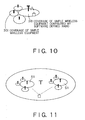
- the cell coverage 34 of the mobile phone unit 3 is the widest, and includes therein the cell coverage 33 of the simple wireless equipment 35, in which the spot area 38, being the cell coverage of the wireless LAN configured by software defined radio 1, is included.
- the information necessary for configuring the wireless LAN used in the spot area 38 by the software defined radio 1 is transmitted in the cell coverage 33.
- the cell coverage 33 of the simple wireless equipment 35 may be established as an annex to the spot area 38, as shown in Fig. 10. In this case, only the user who does not have the wireless equipment used in the spot area 38 needs to visit the cell coverage 33 of the simple wireless equipment 35.
- a spot area arranged in a station or the like users, who use the spot area at the time of commutation every day, may have the wireless equipment configured and already customized by the software defined radio lusable in the spot area.
- a user, who uses the spot area for the first time due to a business trip or the like may not have such wireless equipment usable in the spot area. If user who has configurable wireless equipment like software defined radio 1, he or she drops by the spot area 38 once and gets the information necessary for configuring the equipment.
- the service provider requires personal information, such as authentication procedure, with respect to the user accessing to the spot area.
- a roaming service used in the mobile phone 3 may be used.
- the service provider uses an identification number of a user terminal obtained by the communication using the mobile phone 3 or the simple wireless equipment 35, to refer to the server, in which the user has registered, via the network, thereby obtaining the personal information of the user.
- the mobile phone 3 and the simple wireless equipment 35 are provided in addition to the software defined radio 1.
- the controllers 16 in the mobile phone unit 3, the controller 36 in the simple wireless equipment 35, and the controller 14 in the software defined radio 1 are connected to the control signal line L1, so that it can be informed to the simple wireless equipment 35 and the software defined radio 1 that the mobile phone unit 3 has received a transmission restriction instruction.
- Fig. 11 is a diagram showing one example of a wireless communication system using the wireless communication terminal shown in Fig. 7.
- the wireless communication terminal in Fig. 11 has a plurality of spot areas 51 where different service providers provide services. The user can receive the service provided by the different service providers, while traveling these spot areas 51.
- the communication service in the spot area described above becomes more powerful by cooperating with the PDA or the like.
- Fig. 12 is a block diagram showing the schematic configuration of a wireless communication terminal according to a third embodiment of the present invention.
- the like components as those in Fig. 1 are denoted by the like reference numerals, and the different points will be mainly described below.
- the mobile phone unit is configured by the software defined radio 1, and existing wireless equipment (non-software defined radio) is used as the simple wireless equipment 35.
- the controller 14 in the software defined radio 1 and the controller 36in the simple wireless equipment 35 are connected by the control signal line L1.
- This control signal line L1 is used, for example, to inform the simple wireless equipment 35 that the mobile phone 3 has received the transmission restriction instruction.
- Fig. 13 is a block diagram showing the schematic configuration of a wireless communication terminal according to a fourth embodiment of the present invention.
- the like components as those in Fig. 1 are denoted by the like reference numerals, and the different points will be mainly described below.
- the software defined radio 1 has such a feature that it can correspond to a plurality of wireless systems by using the hardware as it is, but in order to improve the versatileness, it is desirable that replacement or addition of the signal processing unit 12 be possible. Therefore, the wireless communication terminal in Fig. 13 comprises an extended module 39 for extending the function of the software defined radio 1, and an interface section 40 for transferring signals between the software defined radio 1 and the extended module 39.
- the extended module 39 has a configuration generally the same as that of the software defined radio 1, and comprises a radio section 41, a signal processing unit 42, a resource controller 43, a controller 44, a memory 45, and an antenna 46.
- the internal configuration of the extended module 39 is not limited to the one illustrated in Fig. 13.
- the radio section 41 and the antenna 46 may not be provided.
- the number of the extended modules 39 connected to the software defined radio 1 is not limited to one, and a plurality of extended modules 39 may be connected thereto.
- the signal processing unit 12 in the software defined radio 1 and the signal processing unit 42 in the extended module 39 can transfer signals to each other, and the controller 14 in the software defined radio 1 and the controller 44 in the extended module 39 are connected to each other by the control signal line L1.
- This control signal line L1 is used, for example, to inform the extended module 39 that the mobile phone 3 has received the transmission restriction instruction.
- existing simple wireless equipment 35 may be connected to the software defined radio 1.
- the simple wireless equipment 35 can be notified the transmission restriction via line L1.
- the software defined radio 1 can be prevented from transmitting unnecessary radio waves to the surroundings.
- Fig. 14 is a block diagram showing the schematic configuration of a wireless communication terminal according to a fifth embodiment of the present invention.
- the like components as those in Fig. 1 are denoted by the like reference numerals, and the different points will be mainly described below.
- the wireless communication terminal in Fig. 14 comprises a plurality of software defined radio 1, 1a.
- the both units 1 and 1a in the wireless communication terminal are formed of software defined radio technology.
- the mobile phone unit is built in one of the software defined radio 1
- the simple wireless equipment is built in the other software defined radio 1a
- the controllers 14 and 14a are connected by the control signal line L1.
- unnecessary radio wave transmission can be reliably prevented in a desired case, even if there is no obligation to suspend transmission of wireless signals.
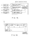
- Fig. 15 is a block diagram showing the schematic configuration of a wireless communication terminal according to the sixth embodiment of the present invention.
- the wireless communication terminal in Fig. 15 comprises a plurality of mobile phone terminal functional units 61 and 62, respectively provided corresponding to a plurality of wireless systems, a plurality of simple wireless terminal functional units 63 and 64, respectively provided corresponding to the plurality of wireless systems, and a transmission suspension control unit 65 that controls transmission suspension of radio waves from the mobile phone terminal functional units 61 and 62 and the simple wireless terminal functional units 63 and 64.
- the mobile phone terminal functional units 61 and 62 stand for W-CDMA, PDC (Personal Digital Cellular, which is the name of Japanese cellular system.), or PHS, and has an obligation to suspend transmission of radio waves under a predetermined condition (for example, when a transmission suspending instruction is given from a base station, when the receiver sensitivity decreases, when the terminal functional unit has a failure, or when a transmission suspending instruction is issued for ensuring important communication).
- the mobile phone terminal functional units 61 and 62 perform wireless communication with a corresponding facility for mobile phones (for example, base stations) 81 and 82.
- the simple wireless terminal functional units 63 and 64 stand for a wireless LAN or Bluetooth (TM), which do not have a particular obligation to suspend transmission of radio waves.
- the simple wireless terminal functional units 63 and 64 respectively perform wireless communication with the corresponding other simple wireless terminals 83 and 84.
- the transmission suspension control unit 65 receives a transmission suspending signal output from any one of the plurality of mobile phone terminal functional units 61 and 62, and transmits a transmission suspension control signal which instructs transmission suspension of radio waves with respect to all other mobile phone terminal functional units 61 and 62 and the simple wireless terminal functional units 63 and 64.
- Fig. 16 is a block diagram showing one example of the internal configuration of the mobile phone terminal functional units 61 and 62, and the simple wireless terminal functional units 63 and 64.
- the mobile phone terminal functional units 61 and 62, and the simple wireless terminal functional units 63 and 64 respectively comprise: a digital unit 71 which generates a digital transmission signal by performing digital signal processing; a D/A conversion unit 72 which converts the digital transmission signal into an analog transmission signal; a modulation unit 73 which performs orthogonal modulation, filtering and frequency conversion of the analog transmission signal to generate a modulation signal; a power amplifying unit 74 which amplifies power of the modulation signal and supplies the signal to an antenna; a power supply unit 75 which supplies power at least to the power amplifying unit 74; and a transmission suspending unit 76 which suspends transmission of radio waves, upon reception of a transmission suspension control signal.
- the digital unit 71 may be formed of a dedicated chip such as ASIC for performing various kinds of signal processing such as error correction, or may be realized by software processing by using a universal chip such as CPU.
- the digital unit 71 Upon reception of a transmission suspension control signal, the digital unit 71 suspends the generation processing of a digital transmission signal, and supplies a transmission suspending signal to the transmission suspending unit 76.
- the transmission suspending unit 76 is formed of, for example, a power switch, and upon reception of the transmission suspending signal, suspends power supply from the power supply unit 75 to the power amplifying unit 74.
- the transmission suspending unit 76 may supply power not only to the power amplifying unit 74 but also to at least one of the digital unit 71, the D/A conversion unit 72, and the modulation unit 73. In this case, the transmission suspending unit 76 prevents power from being supplied from the power supply unit 75 to the respective sections.
- the transmission suspension control unit 65 transmits a transmission suspension control signal to all other mobile phone terminal functional units 61 and 62, and the simple wireless terminal functional units 63 and 64.
- the mobile phone terminal functional units 61 and 62, and the simple wireless terminal functional units 63 and 64 having received this transmission suspension control signal suspend the operation of the digital unit 71, and suspend power supply to the power amplifying unit 74, thereby suspending transmission of radio waves reliably.
- unnecessary radio wave transmission can be avoided, important communication is not interrupted, and radio wave transmission including noise at the time of failure can be also avoided.
- Fig. 17 is a block diagram showing a first modified example of the internal configuration of the mobile phone terminal functional units 61 and 62, and the simple wireless terminal functional units 63 and 64.
- the transmission suspension control signal from the transmission suspension control unit 65 is supplied to the digital unit 71, and also to the transmission suspending unit 76.
- the transmission suspending unit 76 switches whether or not to supply power to the power amplifying unit 74, based on the transmission suspension control signal from the transmission suspension control unit 65.
- Fig. 18 is a block diagram showing a second modified example of the internal configuration of the mobile phone terminal functional units 61 and 62, and the simple wireless terminal functional units 63 and 64.
- the transmission suspension control signal from the transmission suspension control unit 65 is supplied only to the transmission suspending unit 76.
- the operation of the transmission suspending unit 76 is the same as in Fig. 16, but since the transmission suspension control signal is not input to the digital unit 71, the digital unit 71 performs signal processing at all times.
- the power consumption increases as compared with the examples shown in Fig. 16 and Fig. 17, but the processing load of the digital unit 71 is further simplified.
- detecting a failure of the simple wireless terminal functional unit is conducted.
- Fig. 19 is a block diagram showing the schematic configuration of the wireless communication terminal in the seventh embodiment according to the present invention.
- the like components as those in Fig. 15 are denoted by the like reference numerals, and the different points will be mainly described below.
- the wireless communication terminal in Fig. 19 has failure detecting units 66 and 67, which respectively detect whether the simple wireless terminal functional unit 63 or 64 has a failure.
- the corresponding failure detecting unit 66 or 67 supplies a transmission suspending signal to the transmission suspension control unit 65.
- the transmission suspension control unit 65 Upon reception of the transmission suspending signal from either one of the mobile phone terminal functional units 61 and 62, and the simple wireless terminal functional units 63 and 64, the transmission suspension control unit 65 supplies a transmission suspension control signal to all of the mobile phone terminal functional units 61 and 62, and the simple wireless terminal functional units 63 and 64.
- the mobile phone terminal functional units 61 and 62, and the simple wireless terminal functional units 63 and 64 are formed in the same manner as shown in Fig. 16 to Fig. 18.
- Fig. 20 is a block diagram showing the internal configuration of the simple wireless terminal functional units 63 and 64, and the failure detecting units 66 and 67, which detects a failure in the simple wireless terminal functional units 63 and 64.
- the simple wireless terminal functional units 63 and 64 are constructed as shown in Fig. 16, but these may be constructed as shown in Fig. 17 or Fig. 18.
- the failure detecting units 66 and 67 comprise a watchdog timer 77 which judges whether the digital unit 71 in the corresponding simple wireless terminal functional unit 63 or 64 has a failure, and a transmission power measuring unit 78 which judges whether the power amplifying unit 74 has a failure.
- the digital units 71 in the simple wireless terminal functional units 63 and 64 output an operating condition report signal at a predetermined time interval.
- the operating condition report signal is not output at the predetermined time interval from the digital unit 71, there is a high possibility that the corresponding simple wireless terminal functional unit 63 or 64 is malfunctioning, and hence the watchdog timer 77 judges that the simple wireless terminal functional unit 63 or 64 has a failure.
- the transmission power measuring unit 78 monitors amplified power in the power amplifying unit 74, and if the amplified power is not within a defined value, it judges that the power amplifying unit 74 has a failure.
- the failure detecting units 66 and 67 supply a transmission suspending signal to the transmission suspension control unit 65.
- the transmission suspension control unit 65 Upon reception of the transmission suspending signal, the transmission suspension control unit 65 supplies a transmission suspension control signal to all of the mobile phone terminal functional units 61 and 62, and the simple wireless terminal functional units 63 and 64, and the respective functional units having received this signal instruct the transmission suspending unit 76 to suspend power supply from the power supply unit 75 to the power amplifying unit 74.
- the failure detecting units 66 and 67 which detect a failure in the simple wireless terminal functional units 63 and 64 are provided, when either one of the simple wireless terminal functional units 63 and 64 has a failure, transmission of radio waves from all of the mobile phone terminal functional units 61 and 62, and the simple wireless terminal functional units 63 and 64 in the wireless communication terminal can be suspended.
- the mobile phone terminal functional units 61 and 62 are affected by a failure in the simple wireless terminal functional units 63 and 64, such as the wireless LAN system or the Bluetooth (TM) equipment, since radio wave is not transmitted from the mobile phone terminal functional units 61 and 62, an influence to the outside can be avoided.
- the number of the mobile phone terminal functional units 61 and 62 and the simple wireless terminal functional units 63 and 64 included in the wireless communication terminal is not particularly limited.
- the mobile phone terminal functional units 61, 62 and the simple wireless terminal functional units 63, 64 can be configured by software defined radio. At least only one each of the mobile phone terminal functional units 61 and 62 and the simple wireless terminal functional units 63 and 64 needs to be provided. Further, there is no particular limitation on the kind of the specific wireless system of the mobile phone terminal functional units 61 and 62 and the simple wireless terminal functional units 63 and 64 .
Landscapes
- Engineering & Computer Science (AREA)
- Computer Networks & Wireless Communication (AREA)
- Signal Processing (AREA)
- Human Computer Interaction (AREA)
- Mobile Radio Communication Systems (AREA)
- Transceivers (AREA)
Applications Claiming Priority (4)
| Application Number | Priority Date | Filing Date | Title |
|---|---|---|---|
| JP2002287233 | 2002-09-30 | ||
| JP2002285809A JP4045158B2 (ja) | 2002-09-30 | 2002-09-30 | 無線通信端末 |
| JP2002285809 | 2002-09-30 | ||
| JP2002287233A JP3779252B2 (ja) | 2002-09-30 | 2002-09-30 | マルチモード無線端末装置 |
Publications (2)
| Publication Number | Publication Date |
|---|---|
| EP1404060A2 true EP1404060A2 (de) | 2004-03-31 |
| EP1404060A3 EP1404060A3 (de) | 2005-11-23 |
Family
ID=31980648
Family Applications (1)
| Application Number | Title | Priority Date | Filing Date |
|---|---|---|---|
| EP03256149A Withdrawn EP1404060A3 (de) | 2002-09-30 | 2003-09-30 | Drahtloses Kommunikationsendgerät |
Country Status (3)
| Country | Link |
|---|---|
| US (1) | US20040063425A1 (de) |
| EP (1) | EP1404060A3 (de) |
| CN (1) | CN1498009A (de) |
Cited By (13)
| Publication number | Priority date | Publication date | Assignee | Title |
|---|---|---|---|---|
| DE102004047368A1 (de) * | 2004-09-29 | 2006-03-30 | Siemens Ag | Funkgestützte Kommunikationseinrichtung und Verfahren zum Updaten einer funkgestützten Kommunikationseinrichtung |
| WO2009144436A1 (en) * | 2008-05-28 | 2009-12-03 | Mirics Semiconductor Limited | Broadcast receiver system |
| US20100329156A1 (en) * | 2008-02-19 | 2010-12-30 | Nxp B.V. | Software defined radio |
| EP2182756A3 (de) * | 2008-11-04 | 2011-06-08 | Broadcom Corporation | Dienstaggregator zur Zuweisung von Ressourcen an eine Vielzahl von Mehrdienst-Kommunikationsvorrichtungen |
| US8131220B2 (en) | 2008-11-04 | 2012-03-06 | Broadcom Corporation | Management unit for managing a plurality of multiservice communication devices |
| US8195143B2 (en) | 2008-11-04 | 2012-06-05 | Broadcom Corporation | Management unit for facilitating inter-network hand-off for a multiservice communication device |
| US8265690B2 (en) | 2008-11-04 | 2012-09-11 | Broadcom Corporation | Multiservice communication device with logical control channel |
| US8312346B2 (en) | 2009-05-01 | 2012-11-13 | Mirics Semiconductor Limited | Systems and methods for communications |
| US8358978B2 (en) | 2008-11-04 | 2013-01-22 | Broadcom Corporation | Multiservice communication device with cognitive radio transceiver |
| US8467305B2 (en) | 2008-11-04 | 2013-06-18 | Broadcom Corporation | Multiservice communication device with dedicated environmental monitoring |
| US8521222B2 (en) | 2008-11-04 | 2013-08-27 | Broadcom Corporation | Multiservice communication device with dedicated control channel |
| US8855025B2 (en) | 2008-11-04 | 2014-10-07 | Broadcom Corporation | Management unit network for collaboratively managing a plurality of multiservice communication devices |
| US8923774B2 (en) | 2008-11-04 | 2014-12-30 | Broadcom Corporation | Management unit with local agent |
Families Citing this family (36)
| Publication number | Priority date | Publication date | Assignee | Title |
|---|---|---|---|---|
| US6782208B1 (en) * | 1999-11-16 | 2004-08-24 | Motorola, Inc. | Wireless communication device and method having coordinated primary and secondary transmitters |
| CN100440879C (zh) * | 2001-01-25 | 2008-12-03 | 株式会社东芝 | 能适应多个无线通信系统的移动无线通信装置 |
| US7885409B2 (en) | 2002-08-28 | 2011-02-08 | Rockwell Collins, Inc. | Software radio system and method |
| JP2008511267A (ja) * | 2004-08-25 | 2008-04-10 | パッドコム ホールディングズ,インコーポレイテッド | ソフトウェア無線を介したマルチネットワークのシームレスローミング |
| US7193435B2 (en) * | 2005-02-04 | 2007-03-20 | Itt Manufacturing Enterprises, Inc. | Programmable application specific integrated circuit for communication and other applications |
| JP4602187B2 (ja) * | 2005-02-16 | 2010-12-22 | パナソニック株式会社 | マルチモード通信装置 |
| US7856611B2 (en) * | 2005-02-17 | 2010-12-21 | Samsung Electronics Co., Ltd. | Reconfigurable interconnect for use in software-defined radio systems |
| CN101120562B (zh) * | 2005-02-17 | 2010-09-29 | 三星电子株式会社 | 用于软件定义无线电系统中的关联单元及其方法 |
| US7668992B2 (en) * | 2005-02-17 | 2010-02-23 | Samsung Electronics Co., Ltd. | Context-based operation reconfigurable instruction set processor and method of operation |
| US7769912B2 (en) * | 2005-02-17 | 2010-08-03 | Samsung Electronics Co., Ltd. | Multistandard SDR architecture using context-based operation reconfigurable instruction set processors |
| FR2885431A1 (fr) * | 2005-05-03 | 2006-11-10 | France Telecom | Procede de reconfiguration d'une unite de traitement d'informations d'un terminal |
| US7941248B1 (en) * | 2005-08-03 | 2011-05-10 | Rockwell Collins, Inc. | Method and apparatus for implementing and managing avionics functions |
| US8126030B2 (en) * | 2005-08-31 | 2012-02-28 | Motorola Mobility, Inc. | Multi-mode wireless communication device and method |
| US7784029B2 (en) * | 2005-09-30 | 2010-08-24 | Microsoft Corporation | Network service for modularly constructing a software defined radio |
| US7681239B2 (en) * | 2005-09-30 | 2010-03-16 | Microsoft Corporation | Modularly constructing a software defined radio |
| US8396041B2 (en) | 2005-11-08 | 2013-03-12 | Microsoft Corporation | Adapting a communication network to varying conditions |
| US7752530B2 (en) * | 2005-11-10 | 2010-07-06 | Samsung Electronics Co., Ltd. | Apparatus and method for a collision-free parallel turbo decoder in a software-defined radio system |
| US7809410B2 (en) * | 2005-11-15 | 2010-10-05 | Harris Corporation | Power management system for SCA based software defined radio and related method |
| US8381047B2 (en) | 2005-11-30 | 2013-02-19 | Microsoft Corporation | Predicting degradation of a communication channel below a threshold based on data transmission errors |
| US7720506B1 (en) | 2006-07-28 | 2010-05-18 | Rockwell Collins, Inc. | System and method of providing antenna specific front ends for aviation software defined radios |
| US7831255B1 (en) | 2006-07-31 | 2010-11-09 | Rockwell Collins, Inc. | System and method of providing automated availability and integrity verification for aviation software defined radios |
| GB2446623B (en) * | 2007-02-19 | 2009-07-15 | Motorola Inc | A heterogeneous wireless communication system and a method of operation therefor |
| US20090222832A1 (en) * | 2008-02-29 | 2009-09-03 | Dell Products, Lp | System and method of enabling resources within an information handling system |
| US20100035562A1 (en) * | 2008-08-05 | 2010-02-11 | Motorola, Inc. | Method and System for Signal Processing and Transmission |
| US20100033433A1 (en) * | 2008-08-08 | 2010-02-11 | Dell Products, Lp | Display system and method within a reduced resource information handling system |
| US8134565B2 (en) * | 2008-08-08 | 2012-03-13 | Dell Products, Lp | System, module and method of enabling a video interface within a limited resource enabled information handling system |
| WO2010019169A1 (en) * | 2008-08-15 | 2010-02-18 | Lsi Corporation | Rom list-decoding of near codewords |
| US8863268B2 (en) * | 2008-10-29 | 2014-10-14 | Dell Products, Lp | Security module and method within an information handling system |
| US9407694B2 (en) | 2008-10-30 | 2016-08-02 | Dell Products, Lp | System and method of polling with an information handling system |
| US20100261500A1 (en) * | 2009-04-09 | 2010-10-14 | Broadcom Corporation | Multiple frequency band multiple standard information signal modular baseband processing module |
| US8369811B2 (en) * | 2009-07-17 | 2013-02-05 | Dell Products, Lp | System and method for radio antenna sharing in an information handling system |
| US8218940B2 (en) | 2009-08-28 | 2012-07-10 | Dell Products, Lp | System and method for managing multiple independent graphics sources in an information handling system |
| US20110105094A1 (en) * | 2009-10-29 | 2011-05-05 | Microsoft Corporation | Location integration in software defined radio |
| US8457673B2 (en) * | 2010-10-11 | 2013-06-04 | Motorola Mobility Llc | Method and apparatus for radio frequency fingerprint distribution |
| US9748979B2 (en) | 2014-10-04 | 2017-08-29 | Taphere! Technology, Llc | System for providing software defined radio on a device |
| FR3091088B1 (fr) * | 2018-12-21 | 2021-05-14 | Inst Mines Telecom | "procede pour fournir une connectivite radiomobile dans un espace confine par une antenne de television exterieure et systeme associe" |
Family Cites Families (11)
| Publication number | Priority date | Publication date | Assignee | Title |
|---|---|---|---|---|
| CA2154318A1 (en) * | 1994-08-25 | 1996-02-26 | Richard David Poole | Adaptable radio telephone handset |
| US6580921B1 (en) * | 1997-03-04 | 2003-06-17 | Mitsubishi Denki Kabushiki Kaisha | Dual-mode mobile telephone terminal |
| US5966667A (en) * | 1997-07-14 | 1999-10-12 | Motorola, Inc. | Dual mode communication device and method |
| JP3161599B2 (ja) * | 1998-07-10 | 2001-04-25 | 日本電気株式会社 | 移動電話システム |
| US6052600A (en) * | 1998-11-23 | 2000-04-18 | Motorola, Inc. | Software programmable radio and method for configuring |
| JP3574111B2 (ja) * | 1999-07-16 | 2004-10-06 | 三菱電機株式会社 | 移動通信端末装置 |
| US6768901B1 (en) * | 2000-06-02 | 2004-07-27 | General Dynamics Decision Systems, Inc. | Dynamic hardware resource manager for software-defined communications system |
| AU783921B2 (en) * | 2000-11-16 | 2005-12-22 | Symbol Technologies, Inc. | Coexistence techniques in wireless networks |
| JP2002291011A (ja) * | 2001-03-23 | 2002-10-04 | Toshiba Corp | 無線装置及び無線装置のハンドオーバ制御方法 |
| US6954446B2 (en) * | 2002-06-25 | 2005-10-11 | Motorola, Inc. | Multiple mode RF communication device |
| AU2003263782A1 (en) * | 2002-07-12 | 2004-02-02 | Sca Technica, Inc | Self-booting software defined radio module |
-
2003
- 2003-09-29 US US10/671,469 patent/US20040063425A1/en not_active Abandoned
- 2003-09-29 CN CNA03160191XA patent/CN1498009A/zh active Pending
- 2003-09-30 EP EP03256149A patent/EP1404060A3/de not_active Withdrawn
Cited By (16)
| Publication number | Priority date | Publication date | Assignee | Title |
|---|---|---|---|---|
| DE102004047368A1 (de) * | 2004-09-29 | 2006-03-30 | Siemens Ag | Funkgestützte Kommunikationseinrichtung und Verfahren zum Updaten einer funkgestützten Kommunikationseinrichtung |
| US20100329156A1 (en) * | 2008-02-19 | 2010-12-30 | Nxp B.V. | Software defined radio |
| US8687524B2 (en) * | 2008-02-19 | 2014-04-01 | Nxp, B.V. | Software defined radio |
| US8310601B2 (en) | 2008-05-28 | 2012-11-13 | Mirics Semiconductor Limited | Broadcast receiver system |
| WO2009144436A1 (en) * | 2008-05-28 | 2009-12-03 | Mirics Semiconductor Limited | Broadcast receiver system |
| US8521222B2 (en) | 2008-11-04 | 2013-08-27 | Broadcom Corporation | Multiservice communication device with dedicated control channel |
| US8195143B2 (en) | 2008-11-04 | 2012-06-05 | Broadcom Corporation | Management unit for facilitating inter-network hand-off for a multiservice communication device |
| US8265690B2 (en) | 2008-11-04 | 2012-09-11 | Broadcom Corporation | Multiservice communication device with logical control channel |
| US8185099B2 (en) | 2008-11-04 | 2012-05-22 | Broadcom Corporation | Service aggregator for allocating resources to a plurality of multiservice communication devices |
| US8358978B2 (en) | 2008-11-04 | 2013-01-22 | Broadcom Corporation | Multiservice communication device with cognitive radio transceiver |
| US8467305B2 (en) | 2008-11-04 | 2013-06-18 | Broadcom Corporation | Multiservice communication device with dedicated environmental monitoring |
| US8131220B2 (en) | 2008-11-04 | 2012-03-06 | Broadcom Corporation | Management unit for managing a plurality of multiservice communication devices |
| EP2182756A3 (de) * | 2008-11-04 | 2011-06-08 | Broadcom Corporation | Dienstaggregator zur Zuweisung von Ressourcen an eine Vielzahl von Mehrdienst-Kommunikationsvorrichtungen |
| US8855025B2 (en) | 2008-11-04 | 2014-10-07 | Broadcom Corporation | Management unit network for collaboratively managing a plurality of multiservice communication devices |
| US8923774B2 (en) | 2008-11-04 | 2014-12-30 | Broadcom Corporation | Management unit with local agent |
| US8312346B2 (en) | 2009-05-01 | 2012-11-13 | Mirics Semiconductor Limited | Systems and methods for communications |
Also Published As
| Publication number | Publication date |
|---|---|
| US20040063425A1 (en) | 2004-04-01 |
| CN1498009A (zh) | 2004-05-19 |
| EP1404060A3 (de) | 2005-11-23 |
Similar Documents
| Publication | Publication Date | Title |
|---|---|---|
| US20040063425A1 (en) | Wireless communication terminal | |
| FI114272B (fi) | Viestintäkäyttöjärjestelmä ja siihen liittyvä menetelmä | |
| US6091967A (en) | Scalable radio platform | |
| US6526272B1 (en) | Reducing calling costs for wireless phones using multiple mobile identification numbers | |
| US7640009B2 (en) | Method and apparatus to provide a selectable caller identification | |
| US9363391B2 (en) | Wireless device access to communication services through another wireless device | |
| US20040203873A1 (en) | Method and system of informing WAN user of nearby WLAN access point | |
| WO1995023485A1 (en) | Multi-mode communications system | |
| RU2010118515A (ru) | Конфигурирование терминала доступа и управление доступом | |
| KR20070074609A (ko) | 이동 통신 장비 캐퍼빌리티의 선택적인 디스에이블 | |
| US7171233B2 (en) | Method and device for selecting between telecommunication networks | |
| US20090033494A1 (en) | Vehicular mobile rf tags | |
| CN105703789A (zh) | 通信装置及多个无线电活动的处理方法 | |
| US20060094397A1 (en) | Apparatus and method for connecting an emergency call | |
| EP1671208B1 (de) | Verfahren und vorrichtung zum routen von nachrichten in einem netzwerk | |
| US8874163B2 (en) | Method and apparatus for managing sound volume of wireless connection device in mobile communication terminal | |
| US6002948A (en) | Method and apparatus for radio system with mode based subscriber communications | |
| US20140106745A1 (en) | Dynamic wireless transceiver selection in a wireless communication device | |
| KR20000040300A (ko) | 이동 무선 단말기에서 단축메시지 수신 제어방법 | |
| US20060094396A1 (en) | Apparatus and method for connecting an emergency call | |
| JP2002084566A (ja) | 移動体通信システム | |
| JP2006246409A (ja) | 携帯端末、通信システム、通信網選択方法、及びプログラム | |
| FI108605B (fi) | Sijainninhallintamenetelmä, matkaviestin ja järjestelmä | |
| US20030119560A1 (en) | Radio communication control station device and radio communication device | |
| KR20030065123A (ko) | 휴대폰의 로밍시 시간 표시 방법 |
Legal Events
| Date | Code | Title | Description |
|---|---|---|---|
| PUAI | Public reference made under article 153(3) epc to a published international application that has entered the european phase |
Free format text: ORIGINAL CODE: 0009012 |
|
| 17P | Request for examination filed |
Effective date: 20031021 |
|
| AK | Designated contracting states |
Kind code of ref document: A2 Designated state(s): AT BE BG CH CY CZ DE DK EE ES FI FR GB GR HU IE IT LI LU MC NL PT RO SE SI SK TR |
|
| AX | Request for extension of the european patent |
Extension state: AL LT LV MK |
|
| RIC1 | Information provided on ipc code assigned before grant |
Ipc: 7H 04Q 7/32 B Ipc: 7H 04L 12/56 B Ipc: 7H 04L 12/28 A |
|
| PUAL | Search report despatched |
Free format text: ORIGINAL CODE: 0009013 |
|
| AK | Designated contracting states |
Kind code of ref document: A3 Designated state(s): AT BE BG CH CY CZ DE DK EE ES FI FR GB GR HU IE IT LI LU MC NL PT RO SE SI SK TR |
|
| AX | Request for extension of the european patent |
Extension state: AL LT LV MK |
|
| AKX | Designation fees paid |
Designated state(s): DE FR GB |
|
| STAA | Information on the status of an ep patent application or granted ep patent |
Free format text: STATUS: THE APPLICATION IS DEEMED TO BE WITHDRAWN |
|
| 18D | Application deemed to be withdrawn |
Effective date: 20061024 |