EP1403745B1 - Off-line diagnosis system - Google Patents
Off-line diagnosis system Download PDFInfo
- Publication number
- EP1403745B1 EP1403745B1 EP03400057A EP03400057A EP1403745B1 EP 1403745 B1 EP1403745 B1 EP 1403745B1 EP 03400057 A EP03400057 A EP 03400057A EP 03400057 A EP03400057 A EP 03400057A EP 1403745 B1 EP1403745 B1 EP 1403745B1
- Authority
- EP
- European Patent Office
- Prior art keywords
- zone
- diagnosis
- field instrument
- memory
- data
- Prior art date
- Legal status (The legal status is an assumption and is not a legal conclusion. Google has not performed a legal analysis and makes no representation as to the accuracy of the status listed.)
- Expired - Lifetime
Links
Images



Classifications
-
- G—PHYSICS
- G05—CONTROLLING; REGULATING
- G05B—CONTROL OR REGULATING SYSTEMS IN GENERAL; FUNCTIONAL ELEMENTS OF SUCH SYSTEMS; MONITORING OR TESTING ARRANGEMENTS FOR SUCH SYSTEMS OR ELEMENTS
- G05B23/00—Testing or monitoring of control systems or parts thereof
- G05B23/02—Electric testing or monitoring
- G05B23/0205—Electric testing or monitoring by means of a monitoring system capable of detecting and responding to faults
- G05B23/0208—Electric testing or monitoring by means of a monitoring system capable of detecting and responding to faults characterized by the configuration of the monitoring system
- G05B23/021—Electric testing or monitoring by means of a monitoring system capable of detecting and responding to faults characterized by the configuration of the monitoring system adopting a different treatment of each operating region or a different mode of the monitored system, e.g. transient modes; different operating configurations of monitored system
-
- G—PHYSICS
- G05—CONTROLLING; REGULATING
- G05B—CONTROL OR REGULATING SYSTEMS IN GENERAL; FUNCTIONAL ELEMENTS OF SUCH SYSTEMS; MONITORING OR TESTING ARRANGEMENTS FOR SUCH SYSTEMS OR ELEMENTS
- G05B19/00—Program-control systems
- G05B19/02—Program-control systems electric
- G05B19/418—Total factory control, i.e. centrally controlling a plurality of machines, e.g. direct or distributed numerical control [DNC], flexible manufacturing systems [FMS], integrated manufacturing systems [IMS] or computer integrated manufacturing [CIM]
- G05B19/4185—Total factory control, i.e. centrally controlling a plurality of machines, e.g. direct or distributed numerical control [DNC], flexible manufacturing systems [FMS], integrated manufacturing systems [IMS] or computer integrated manufacturing [CIM] characterised by the network communication
-
- G—PHYSICS
- G05—CONTROLLING; REGULATING
- G05B—CONTROL OR REGULATING SYSTEMS IN GENERAL; FUNCTIONAL ELEMENTS OF SUCH SYSTEMS; MONITORING OR TESTING ARRANGEMENTS FOR SUCH SYSTEMS OR ELEMENTS
- G05B23/00—Testing or monitoring of control systems or parts thereof
- G05B23/02—Electric testing or monitoring
- G05B23/0205—Electric testing or monitoring by means of a monitoring system capable of detecting and responding to faults
- G05B23/0218—Electric testing or monitoring by means of a monitoring system capable of detecting and responding to faults characterised by the fault detection method dealing with either existing or incipient faults
- G05B23/0221—Preprocessing measurements, e.g. data collection rate adjustment; Standardization of measurements; Time series or signal analysis, e.g. frequency analysis or wavelets; Trustworthiness of measurements; Indexes therefor; Measurements using easily measured parameters to estimate parameters difficult to measure; Virtual sensor creation; De-noising; Sensor fusion; Unconventional preprocessing inherently present in specific fault detection methods like PCA-based methods
-
- G—PHYSICS
- G05—CONTROLLING; REGULATING
- G05B—CONTROL OR REGULATING SYSTEMS IN GENERAL; FUNCTIONAL ELEMENTS OF SUCH SYSTEMS; MONITORING OR TESTING ARRANGEMENTS FOR SUCH SYSTEMS OR ELEMENTS
- G05B23/00—Testing or monitoring of control systems or parts thereof
- G05B23/02—Electric testing or monitoring
- G05B23/0205—Electric testing or monitoring by means of a monitoring system capable of detecting and responding to faults
- G05B23/0218—Electric testing or monitoring by means of a monitoring system capable of detecting and responding to faults characterised by the fault detection method dealing with either existing or incipient faults
- G05B23/0256—Electric testing or monitoring by means of a monitoring system capable of detecting and responding to faults characterised by the fault detection method dealing with either existing or incipient faults injecting test signals and analyzing monitored process response, e.g. injecting the test signal while interrupting the normal operation of the monitored system; superimposing the test signal onto a control signal during normal operation of the monitored system
-
- G—PHYSICS
- G05—CONTROLLING; REGULATING
- G05B—CONTROL OR REGULATING SYSTEMS IN GENERAL; FUNCTIONAL ELEMENTS OF SUCH SYSTEMS; MONITORING OR TESTING ARRANGEMENTS FOR SUCH SYSTEMS OR ELEMENTS
- G05B2219/00—Program-control systems
- G05B2219/30—Nc systems
- G05B2219/31—From computer integrated manufacturing till monitoring
- G05B2219/31211—Communicate diagnostic data from intelligent field device controller to central
-
- G—PHYSICS
- G05—CONTROLLING; REGULATING
- G05B—CONTROL OR REGULATING SYSTEMS IN GENERAL; FUNCTIONAL ELEMENTS OF SUCH SYSTEMS; MONITORING OR TESTING ARRANGEMENTS FOR SUCH SYSTEMS OR ELEMENTS
- G05B2219/00—Program-control systems
- G05B2219/30—Nc systems
- G05B2219/33—Director till display
- G05B2219/33326—Analyzer, diagnostic for servovalve
-
- G—PHYSICS
- G05—CONTROLLING; REGULATING
- G05B—CONTROL OR REGULATING SYSTEMS IN GENERAL; FUNCTIONAL ELEMENTS OF SUCH SYSTEMS; MONITORING OR TESTING ARRANGEMENTS FOR SUCH SYSTEMS OR ELEMENTS
- G05B2219/00—Program-control systems
- G05B2219/30—Nc systems
- G05B2219/33—Director till display
- G05B2219/33331—Test, diagnostic of field device for correct device, correct parameters
-
- Y—GENERAL TAGGING OF NEW TECHNOLOGICAL DEVELOPMENTS; GENERAL TAGGING OF CROSS-SECTIONAL TECHNOLOGIES SPANNING OVER SEVERAL SECTIONS OF THE IPC; TECHNICAL SUBJECTS COVERED BY FORMER USPC CROSS-REFERENCE ART COLLECTIONS [XRACs] AND DIGESTS
- Y02—TECHNOLOGIES OR APPLICATIONS FOR MITIGATION OR ADAPTATION AGAINST CLIMATE CHANGE
- Y02P—CLIMATE CHANGE MITIGATION TECHNOLOGIES IN THE PRODUCTION OR PROCESSING OF GOODS
- Y02P90/00—Enabling technologies with a potential contribution to greenhouse gas [GHG] emissions mitigation
- Y02P90/02—Total factory control, e.g. smart factories, flexible manufacturing systems [FMS] or integrated manufacturing systems [IMS]
Definitions
- the present invention relates to an off-line diagnosis system in a process control system comprising a host application and field instruments that perform digital communication with the application.
- FIG. 1 is a function block diagram illustrating the technological details of the prior patent application.
- Block 1 denotes a field instrument (for example, valve positioner), which communicates with a host system to perform process control (measurement, operation, monitoring, etc.).
- numeral 101 denotes a data transmit means
- numeral 102 denotes a data analyzing means
- numeral 103 denotes an input-output characteristics measurement means
- numeral 103 denotes a step response measurement means.
- Block 2 denotes a host application that runs on a PC or DCS.
- numeral 201 denotes a data receiving means
- numeral 202 denotes a data analyzing means
- numeral 203 denotes a data display means.
- Numeral 3 denotes a digital 1 communication bus that connects between the data transmit means 101 of the field instrument and the data receiving means 201 of the host application.
- digital communication means communication based, for example, on a communication protocol for the process industry, such as Foundation Fieldbus, PROFIBUS, HART or BRAIN.
- Both the data analyzing means 102 and 202 may be provided in either field instrument 1 or host application 2, or may be omitted in cases where the operator himself /herself makes analyses using measured data.
- field instrument 1 is a valve positioner
- the input-output characteristics of a control valve or a positioner are measured by input-output characteristics measurement means 103
- step responses response characteristics including those of valves
- step response measurement means 104 the data thus measured are analyzed by the data analyzing means as necessary and uploaded to the data receiving means 201 of host application 2 through data transmit means 101 and digital communication bus 3.
- the measured data or analyzed data that has been received is further analyzed by data analyzing means 202 at higher levels as necessary, and the results of analysis are displayed by data display means 203.
- the data memory means in this case refers to memory resources.
- Memory resources are also used for other types of signal processing and, therefore, it is sometimes difficult in terms of cost to secure sufficient memory to store the required data.
- An object of the present invention is to provide an off-line diagnosis system whereby the measurement resolution (number of measurement points) can be increased in order to obtain detailed input-output characteristics, and step response characteristics can be obtained at a sufficient frequency and more efficiently, without expanding the physically limited memory capacity of a field instrument or host application.
- US 6,272,401 relates to a valve positioner system adapted for monitoring several valve positions.
- the invention relates to a system as claimed in claim 1 and to a method as claimed in claim 12.
- the field instrument retains the diagnosis results data of one zone among the plurality of zones in data memory means with a given memory capacity and, while transmitting the retained data to the host application, also retains the diagnosis results data of another zone in the data memory means to communicate the retained data to the host application.
- the self-diagnosis or valve diagnosis is based on input-output characteristics measurement in which an input is given to the field instrument or valve and then the output value thereof is measured.
- the self-diagnosis or valve diagnosis is further based on measurement of response characteristics in which a step input is given to the field instrument and then the output value thereof is measured.
- the data analyzing systems are provided in either the field instrument or host application or in both.
- the field instrument is a valve positioner, preferably an electro-pneumatic converter.
- FIG. 2 is a function block diagram illustrating an example of an off-line diagnosis system to which the present invention has been applied. Elements identical to those discussed in the prior art system of FIG. 1 are referenced alike and excluded from the description hereunder.
- the system of the present invention is characterized by a configuration in which data memory means 105 and measurement control means 106 are provided in field instrument 1, and data memory means 204 and display control means 205 are provided in host application 2.
- the methods of measurement for diagnostic purposes described in the present invention are characterized by the features that the range of dummy inputs is divided into a plurality of zones in field instrument 1 and the diagnosis results of each zone are successively communicated to host application 2.
- the diagnosis results data of one zone among a plurality of zones is retained in data memory means 105 with a given capacity.
- field instrument 1 While transmitting the retained data to the host application, field instrument 1 stores the diagnosis results data of another zone in the data memory means after resetting or overwriting the previous data, and communicates the stored data to host application 2.
- diagnosis results data of one zone received from field instrument 1 is retained in data memory means 204 using the functions of display control means 205 that works in conjunction with measurement control means 106, analyzed by data analyzing means 202, and then displayed by data display means 203.
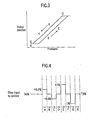
- FIG. 3 is a conceptual view showing the method of measuring the input-output characteristics of a valve positioner having hysteresis.
- the data retention capacity of data memory means 105 is nl measurement points and it is necessary to measure more than nl points in order to increase the resolution, then the input range of a signal (pressure signal in this case) for diagnosis is divided into a plurality of zones.
- FIG. 4 is a conceptual view showing the method of measuring such step response characteristics of a valve positioner as illustrated in FIG. 5 .
- eight zones from zone A to zone H are measured.
- nl points are measured and another step input is given after the completion of measurement of each zone.
- dummy inputs at levels around the median level of 50% are given: 50.5% in zone A, 50% in zone B, 49.5% in zone C, 50% in zone D, 51% in zone E, 50% in zone F, 49% in zone G, and 50% in zone H, thus acquiring nl items of step response data for each zone. Consequently, the total number of measurement points amounts to n1 x 8.
- FIG. 5 is a characteristic graph typical of a step response.
- step response characteristics include gradually increasing (or decreasing) the step width, for example, from 0.5% to 1%, 2%, 5%, 10%, and to 20% to test the valve positioner.
- inputs may be provided at a specific step interval, for example, from 0%, to 25%, 50%, 75%, 100%, 75%, 50%, 25%, and to 0%, to test the up-down step response characteristics of the valve positioner.
- valve positioner is adopted as the field instrument
- the embodiments may also be applied to the self-diagnosis of the input-output characteristics of an electro-pneumatic converter or motor valve.
- the embodiments may also be applied to general field instruments other than control means, such as valve positioners or motor valves.
Landscapes
- Engineering & Computer Science (AREA)
- Physics & Mathematics (AREA)
- General Physics & Mathematics (AREA)
- Automation & Control Theory (AREA)
- General Engineering & Computer Science (AREA)
- Manufacturing & Machinery (AREA)
- Quality & Reliability (AREA)
- Testing And Monitoring For Control Systems (AREA)
- Arrangements For Transmission Of Measured Signals (AREA)
- Electronic Switches (AREA)
- Steering Control In Accordance With Driving Conditions (AREA)
Applications Claiming Priority (2)
| Application Number | Priority Date | Filing Date | Title |
|---|---|---|---|
| JP2002286153 | 2002-09-30 | ||
| JP2002286153A JP2004126688A (ja) | 2002-09-30 | 2002-09-30 | オフライン診断システム |
Publications (3)
| Publication Number | Publication Date |
|---|---|
| EP1403745A2 EP1403745A2 (en) | 2004-03-31 |
| EP1403745A3 EP1403745A3 (en) | 2005-03-23 |
| EP1403745B1 true EP1403745B1 (en) | 2008-05-21 |
Family
ID=31973408
Family Applications (1)
| Application Number | Title | Priority Date | Filing Date |
|---|---|---|---|
| EP03400057A Expired - Lifetime EP1403745B1 (en) | 2002-09-30 | 2003-09-29 | Off-line diagnosis system |
Country Status (5)
| Country | Link |
|---|---|
| US (2) | US6941244B1 (enExample) |
| EP (1) | EP1403745B1 (enExample) |
| JP (1) | JP2004126688A (enExample) |
| AT (1) | ATE396440T1 (enExample) |
| DE (1) | DE60321105D1 (enExample) |
Families Citing this family (12)
| Publication number | Priority date | Publication date | Assignee | Title |
|---|---|---|---|---|
| JP2003308101A (ja) * | 2002-04-16 | 2003-10-31 | Yokogawa Electric Corp | オフライン診断システム |
| US8509926B2 (en) * | 2005-12-05 | 2013-08-13 | Fisher-Rosemount Systems, Inc. | Self-diagnostic process control loop for a process plant |
| DE102012204960B4 (de) * | 2012-03-28 | 2024-12-19 | Robert Bosch Gmbh | Interlockdetektor mit Selbstdiagnosefunktion für einen Interlockkreis und ein Verfahren zur Selbstdiagnose des Interlockdetektors |
| EP2799946B1 (de) * | 2013-05-03 | 2016-10-05 | Pepperl + Fuchs GmbH | Verfahren zur Kompatibilitätsherstellung zwischen einem Feldgerät und einer Diagnoseeinrichtung und Interfacegerät |
| JP6163413B2 (ja) * | 2013-11-22 | 2017-07-12 | アズビル株式会社 | 機器管理システムおよび機器管理方法 |
| US9810345B2 (en) * | 2013-12-19 | 2017-11-07 | Dresser, Inc. | Methods to improve online diagnostics of valve assemblies on a process line and implementation thereof |
| CN107191666B (zh) * | 2017-05-23 | 2019-09-17 | 浙江理工大学 | 面向天然气分输站的安全切断阀性能监测方法及系统 |
| US11808260B2 (en) | 2020-06-15 | 2023-11-07 | Schlumberger Technology Corporation | Mud pump valve leak detection and forecasting |
| US12158046B2 (en) | 2020-06-22 | 2024-12-03 | Schlumberger Technology Corporation | Maintaining torque wrenches using a predictive model |
| US12000260B2 (en) | 2020-07-27 | 2024-06-04 | Schlumberger Technology Corporation | Monitoring and diagnosis of equipment health |
| US12379707B2 (en) | 2020-10-23 | 2025-08-05 | Schlumberger Technology Corporation | Monitoring equipment health |
| JP2025077626A (ja) | 2023-11-07 | 2025-05-19 | 横河電機株式会社 | フィールド機器及び診断方法 |
Family Cites Families (12)
| Publication number | Priority date | Publication date | Assignee | Title |
|---|---|---|---|---|
| US5109692A (en) | 1988-08-25 | 1992-05-05 | Fisher Controls International Inc. | Diagnostic apparatus and method for fluid control valves |
| US4976144A (en) | 1988-08-25 | 1990-12-11 | Fisher Controls International, Inc. | Diagnostic apparatus and method for fluid control valves |
| US5197328A (en) | 1988-08-25 | 1993-03-30 | Fisher Controls International, Inc. | Diagnostic apparatus and method for fluid control valves |
| US5687098A (en) | 1995-10-30 | 1997-11-11 | Fisher Controls International, Inc. | Device data acquisition |
| US5970430A (en) * | 1996-10-04 | 1999-10-19 | Fisher Controls International, Inc. | Local device and process diagnostics in a process control network having distributed control functions |
| US5892690A (en) | 1997-03-10 | 1999-04-06 | Purechoice, Inc. | Environment monitoring system |
| JPH10336238A (ja) | 1997-06-05 | 1998-12-18 | Sony Corp | 情報処理システム、携帯端末、サーバ、及びデータ処理方法 |
| US6272401B1 (en) | 1997-07-23 | 2001-08-07 | Dresser Industries, Inc. | Valve positioner system |
| DE19732046A1 (de) * | 1997-07-25 | 1999-01-28 | Abb Patent Gmbh | Prozeßdiagnosesystem und Verfahren zur Diagnose von Vorgängen und Zuständen eines technischen Prozesses |
| US6466893B1 (en) | 1997-09-29 | 2002-10-15 | Fisher Controls International, Inc. | Statistical determination of estimates of process control loop parameters |
| US6049764A (en) * | 1997-11-12 | 2000-04-11 | City Of Hope | Method and system for real-time control of analytical and diagnostic instruments |
| US6834258B2 (en) * | 2002-12-31 | 2004-12-21 | Rosemount, Inc. | Field transmitter with diagnostic self-test mode |
-
2002
- 2002-09-30 JP JP2002286153A patent/JP2004126688A/ja active Pending
-
2003
- 2003-09-18 US US10/665,791 patent/US6941244B1/en not_active Expired - Lifetime
- 2003-09-29 AT AT03400057T patent/ATE396440T1/de not_active IP Right Cessation
- 2003-09-29 EP EP03400057A patent/EP1403745B1/en not_active Expired - Lifetime
- 2003-09-29 DE DE60321105T patent/DE60321105D1/de not_active Expired - Lifetime
-
2005
- 2005-05-26 US US11/138,583 patent/US7181367B2/en not_active Expired - Lifetime
Also Published As
| Publication number | Publication date |
|---|---|
| US20050216232A1 (en) | 2005-09-29 |
| US6941244B1 (en) | 2005-09-06 |
| EP1403745A2 (en) | 2004-03-31 |
| JP2004126688A (ja) | 2004-04-22 |
| ATE396440T1 (de) | 2008-06-15 |
| EP1403745A3 (en) | 2005-03-23 |
| US7181367B2 (en) | 2007-02-20 |
| DE60321105D1 (de) | 2008-07-03 |
Similar Documents
| Publication | Publication Date | Title |
|---|---|---|
| US6941244B1 (en) | Off-line diagnosis system | |
| EP1147301B1 (en) | Method and device in vehicle control system, and system for error diagnostics in vehicle | |
| EP2410438A1 (en) | Method and telemetric device for resampling time series data | |
| EP2990706B1 (en) | Device and method for valve signature testing | |
| CN101828152A (zh) | 用于操作具有至少两个测量信道的过程自动化技术的现场设备的方法和适用于实施该方法的具有至少两个测量信道的过程自动化技术的现场设备 | |
| KR101363045B1 (ko) | 머징유닛 성능 검사장치 | |
| EP2652461A1 (de) | Verfahren zur überwachung der funktion eines feldgeräts | |
| JP2007532050A (ja) | インターフェースチップによって受信されたdlpduを外部回路によってなされたデータ計測に関連付けるためのシステムおよび方法 | |
| EP0430297A2 (en) | Method and system for testing specimen of automotive power transmission connected to engine and analyzing engine output characteristic via specimen tested using dynamometer | |
| EP1370021B1 (en) | Test point selection for constructing bit error rate diagrams | |
| EP1486841B1 (de) | Verfahren zur Funktionsanzeige eines Feldgerätes der Prozessautomatisierungstechnik | |
| JP4771855B2 (ja) | サーバ装置、およびプログラム | |
| JP2001505720A (ja) | アナログ・インターフェース回路 | |
| CN115308517B (zh) | 一种元器件的老化检测方法、系统、存储介质和设备 | |
| CN114545107B (zh) | 用测量仪器监视过程设备中测量的被测变量的方法 | |
| CN112352266B (zh) | 用于在飞机中交换数据的系统 | |
| CN100571166C (zh) | 一种基于网络分析仪的测试方法和装置 | |
| CN113935144A (zh) | 用于空调室外机振动噪声分析的方法、装置及设备 | |
| US20200358797A1 (en) | Work machine and method for monitoring a control system at a work machine | |
| KR19980085500A (ko) | 계측기기 검교정 자동화 시스템 | |
| RU155504U1 (ru) | Устройство диагностики состояния поршневого компрессора | |
| KR20030029356A (ko) | 차량 진단 시스템 | |
| KR20050094556A (ko) | 시험 자동화 시스템 및 방법 | |
| JP2003308101A (ja) | オフライン診断システム | |
| CN119178606A (zh) | 一种测试混动变速器中离合器传递扭矩能力的系统及方法 |
Legal Events
| Date | Code | Title | Description |
|---|---|---|---|
| PUAI | Public reference made under article 153(3) epc to a published international application that has entered the european phase |
Free format text: ORIGINAL CODE: 0009012 |
|
| AK | Designated contracting states |
Kind code of ref document: A2 Designated state(s): AT BE BG CH CY CZ DE DK EE ES FI FR GB GR HU IE IT LI LU MC NL PT RO SE SI SK TR |
|
| AX | Request for extension of the european patent |
Extension state: AL LT LV MK |
|
| PUAL | Search report despatched |
Free format text: ORIGINAL CODE: 0009013 |
|
| AK | Designated contracting states |
Kind code of ref document: A3 Designated state(s): AT BE BG CH CY CZ DE DK EE ES FI FR GB GR HU IE IT LI LU MC NL PT RO SE SI SK TR |
|
| AX | Request for extension of the european patent |
Extension state: AL LT LV MK |
|
| 17P | Request for examination filed |
Effective date: 20050630 |
|
| AKX | Designation fees paid |
Designated state(s): AT BE BG CH CY CZ DE DK EE ES FI FR GB GR HU IE IT LI LU MC NL PT RO SE SI SK TR |
|
| 17Q | First examination report despatched |
Effective date: 20061023 |
|
| GRAP | Despatch of communication of intention to grant a patent |
Free format text: ORIGINAL CODE: EPIDOSNIGR1 |
|
| GRAS | Grant fee paid |
Free format text: ORIGINAL CODE: EPIDOSNIGR3 |
|
| GRAA | (expected) grant |
Free format text: ORIGINAL CODE: 0009210 |
|
| AK | Designated contracting states |
Kind code of ref document: B1 Designated state(s): AT BE BG CH CY CZ DE DK EE ES FI FR GB GR HU IE IT LI LU MC NL PT RO SE SI SK TR |
|
| REG | Reference to a national code |
Ref country code: GB Ref legal event code: FG4D |
|
| REG | Reference to a national code |
Ref country code: CH Ref legal event code: EP |
|
| REF | Corresponds to: |
Ref document number: 60321105 Country of ref document: DE Date of ref document: 20080703 Kind code of ref document: P |
|
| REG | Reference to a national code |
Ref country code: IE Ref legal event code: FG4D |
|
| PG25 | Lapsed in a contracting state [announced via postgrant information from national office to epo] |
Ref country code: SI Free format text: LAPSE BECAUSE OF FAILURE TO SUBMIT A TRANSLATION OF THE DESCRIPTION OR TO PAY THE FEE WITHIN THE PRESCRIBED TIME-LIMIT Effective date: 20080521 |
|
| PG25 | Lapsed in a contracting state [announced via postgrant information from national office to epo] |
Ref country code: ES Free format text: LAPSE BECAUSE OF FAILURE TO SUBMIT A TRANSLATION OF THE DESCRIPTION OR TO PAY THE FEE WITHIN THE PRESCRIBED TIME-LIMIT Effective date: 20080901 Ref country code: FI Free format text: LAPSE BECAUSE OF FAILURE TO SUBMIT A TRANSLATION OF THE DESCRIPTION OR TO PAY THE FEE WITHIN THE PRESCRIBED TIME-LIMIT Effective date: 20080521 |
|
| NLV1 | Nl: lapsed or annulled due to failure to fulfill the requirements of art. 29p and 29m of the patents act | ||
| PG25 | Lapsed in a contracting state [announced via postgrant information from national office to epo] |
Ref country code: NL Free format text: LAPSE BECAUSE OF FAILURE TO SUBMIT A TRANSLATION OF THE DESCRIPTION OR TO PAY THE FEE WITHIN THE PRESCRIBED TIME-LIMIT Effective date: 20080521 Ref country code: AT Free format text: LAPSE BECAUSE OF FAILURE TO SUBMIT A TRANSLATION OF THE DESCRIPTION OR TO PAY THE FEE WITHIN THE PRESCRIBED TIME-LIMIT Effective date: 20080521 |
|
| PG25 | Lapsed in a contracting state [announced via postgrant information from national office to epo] |
Ref country code: SE Free format text: LAPSE BECAUSE OF FAILURE TO SUBMIT A TRANSLATION OF THE DESCRIPTION OR TO PAY THE FEE WITHIN THE PRESCRIBED TIME-LIMIT Effective date: 20080821 Ref country code: PT Free format text: LAPSE BECAUSE OF FAILURE TO SUBMIT A TRANSLATION OF THE DESCRIPTION OR TO PAY THE FEE WITHIN THE PRESCRIBED TIME-LIMIT Effective date: 20081021 Ref country code: DK Free format text: LAPSE BECAUSE OF FAILURE TO SUBMIT A TRANSLATION OF THE DESCRIPTION OR TO PAY THE FEE WITHIN THE PRESCRIBED TIME-LIMIT Effective date: 20080521 Ref country code: CZ Free format text: LAPSE BECAUSE OF FAILURE TO SUBMIT A TRANSLATION OF THE DESCRIPTION OR TO PAY THE FEE WITHIN THE PRESCRIBED TIME-LIMIT Effective date: 20080521 |
|
| PG25 | Lapsed in a contracting state [announced via postgrant information from national office to epo] |
Ref country code: RO Free format text: LAPSE BECAUSE OF FAILURE TO SUBMIT A TRANSLATION OF THE DESCRIPTION OR TO PAY THE FEE WITHIN THE PRESCRIBED TIME-LIMIT Effective date: 20080521 Ref country code: BE Free format text: LAPSE BECAUSE OF FAILURE TO SUBMIT A TRANSLATION OF THE DESCRIPTION OR TO PAY THE FEE WITHIN THE PRESCRIBED TIME-LIMIT Effective date: 20080521 Ref country code: SK Free format text: LAPSE BECAUSE OF FAILURE TO SUBMIT A TRANSLATION OF THE DESCRIPTION OR TO PAY THE FEE WITHIN THE PRESCRIBED TIME-LIMIT Effective date: 20080521 |
|
| PLBE | No opposition filed within time limit |
Free format text: ORIGINAL CODE: 0009261 |
|
| STAA | Information on the status of an ep patent application or granted ep patent |
Free format text: STATUS: NO OPPOSITION FILED WITHIN TIME LIMIT |
|
| 26N | No opposition filed |
Effective date: 20090224 |
|
| PG25 | Lapsed in a contracting state [announced via postgrant information from national office to epo] |
Ref country code: BG Free format text: LAPSE BECAUSE OF FAILURE TO SUBMIT A TRANSLATION OF THE DESCRIPTION OR TO PAY THE FEE WITHIN THE PRESCRIBED TIME-LIMIT Effective date: 20080821 Ref country code: EE Free format text: LAPSE BECAUSE OF FAILURE TO SUBMIT A TRANSLATION OF THE DESCRIPTION OR TO PAY THE FEE WITHIN THE PRESCRIBED TIME-LIMIT Effective date: 20080521 Ref country code: MC Free format text: LAPSE BECAUSE OF NON-PAYMENT OF DUE FEES Effective date: 20080930 |
|
| REG | Reference to a national code |
Ref country code: CH Ref legal event code: PL |
|
| REG | Reference to a national code |
Ref country code: IE Ref legal event code: MM4A |
|
| PG25 | Lapsed in a contracting state [announced via postgrant information from national office to epo] |
Ref country code: IE Free format text: LAPSE BECAUSE OF NON-PAYMENT OF DUE FEES Effective date: 20080929 |
|
| PG25 | Lapsed in a contracting state [announced via postgrant information from national office to epo] |
Ref country code: CH Free format text: LAPSE BECAUSE OF NON-PAYMENT OF DUE FEES Effective date: 20080930 Ref country code: LI Free format text: LAPSE BECAUSE OF NON-PAYMENT OF DUE FEES Effective date: 20080930 |
|
| PG25 | Lapsed in a contracting state [announced via postgrant information from national office to epo] |
Ref country code: LU Free format text: LAPSE BECAUSE OF NON-PAYMENT OF DUE FEES Effective date: 20080929 Ref country code: CY Free format text: LAPSE BECAUSE OF FAILURE TO SUBMIT A TRANSLATION OF THE DESCRIPTION OR TO PAY THE FEE WITHIN THE PRESCRIBED TIME-LIMIT Effective date: 20080521 Ref country code: HU Free format text: LAPSE BECAUSE OF FAILURE TO SUBMIT A TRANSLATION OF THE DESCRIPTION OR TO PAY THE FEE WITHIN THE PRESCRIBED TIME-LIMIT Effective date: 20081122 |
|
| PG25 | Lapsed in a contracting state [announced via postgrant information from national office to epo] |
Ref country code: TR Free format text: LAPSE BECAUSE OF FAILURE TO SUBMIT A TRANSLATION OF THE DESCRIPTION OR TO PAY THE FEE WITHIN THE PRESCRIBED TIME-LIMIT Effective date: 20080521 |
|
| PG25 | Lapsed in a contracting state [announced via postgrant information from national office to epo] |
Ref country code: GR Free format text: LAPSE BECAUSE OF FAILURE TO SUBMIT A TRANSLATION OF THE DESCRIPTION OR TO PAY THE FEE WITHIN THE PRESCRIBED TIME-LIMIT Effective date: 20080822 |
|
| PGFP | Annual fee paid to national office [announced via postgrant information from national office to epo] |
Ref country code: GB Payment date: 20140929 Year of fee payment: 12 |
|
| REG | Reference to a national code |
Ref country code: FR Ref legal event code: PLFP Year of fee payment: 13 |
|
| PGFP | Annual fee paid to national office [announced via postgrant information from national office to epo] |
Ref country code: FR Payment date: 20150917 Year of fee payment: 13 |
|
| PGFP | Annual fee paid to national office [announced via postgrant information from national office to epo] |
Ref country code: IT Payment date: 20150923 Year of fee payment: 13 |
|
| PGFP | Annual fee paid to national office [announced via postgrant information from national office to epo] |
Ref country code: DE Payment date: 20150929 Year of fee payment: 13 |
|
| GBPC | Gb: european patent ceased through non-payment of renewal fee |
Effective date: 20150929 |
|
| PG25 | Lapsed in a contracting state [announced via postgrant information from national office to epo] |
Ref country code: GB Free format text: LAPSE BECAUSE OF NON-PAYMENT OF DUE FEES Effective date: 20150929 |
|
| REG | Reference to a national code |
Ref country code: DE Ref legal event code: R119 Ref document number: 60321105 Country of ref document: DE |
|
| REG | Reference to a national code |
Ref country code: FR Ref legal event code: ST Effective date: 20170531 |
|
| PG25 | Lapsed in a contracting state [announced via postgrant information from national office to epo] |
Ref country code: FR Free format text: LAPSE BECAUSE OF NON-PAYMENT OF DUE FEES Effective date: 20160930 Ref country code: DE Free format text: LAPSE BECAUSE OF NON-PAYMENT OF DUE FEES Effective date: 20170401 |
|
| PG25 | Lapsed in a contracting state [announced via postgrant information from national office to epo] |
Ref country code: IT Free format text: LAPSE BECAUSE OF NON-PAYMENT OF DUE FEES Effective date: 20160929 |