EP1403584A1 - Turbinenfederklammerdichtung - Google Patents
Turbinenfederklammerdichtung Download PDFInfo
- Publication number
- EP1403584A1 EP1403584A1 EP20030077778 EP03077778A EP1403584A1 EP 1403584 A1 EP1403584 A1 EP 1403584A1 EP 20030077778 EP20030077778 EP 20030077778 EP 03077778 A EP03077778 A EP 03077778A EP 1403584 A1 EP1403584 A1 EP 1403584A1
- Authority
- EP
- European Patent Office
- Prior art keywords
- turbine
- housing
- transition section
- slots
- seal
- Prior art date
- Legal status (The legal status is an assumption and is not a legal conclusion. Google has not performed a legal analysis and makes no representation as to the accuracy of the status listed.)
- Granted
Links
- 238000007789 sealing Methods 0.000 claims abstract description 41
- 230000007704 transition Effects 0.000 claims description 45
- 239000011248 coating agent Substances 0.000 claims 1
- 238000000576 coating method Methods 0.000 claims 1
- 239000012530 fluid Substances 0.000 abstract description 8
- 239000000446 fuel Substances 0.000 abstract description 4
- 239000007789 gas Substances 0.000 abstract description 4
- 239000000463 material Substances 0.000 description 16
- 230000008901 benefit Effects 0.000 description 5
- PXHVJJICTQNCMI-UHFFFAOYSA-N Nickel Chemical compound [Ni] PXHVJJICTQNCMI-UHFFFAOYSA-N 0.000 description 4
- 238000000034 method Methods 0.000 description 4
- 229910052759 nickel Inorganic materials 0.000 description 2
- 230000006978 adaptation Effects 0.000 description 1
- 238000007743 anodising Methods 0.000 description 1
- 239000003638 chemical reducing agent Substances 0.000 description 1
- UFGZSIPAQKLCGR-UHFFFAOYSA-N chromium carbide Chemical compound [Cr]#C[Cr]C#[Cr] UFGZSIPAQKLCGR-UHFFFAOYSA-N 0.000 description 1
- 238000007598 dipping method Methods 0.000 description 1
- 230000008030 elimination Effects 0.000 description 1
- 238000003379 elimination reaction Methods 0.000 description 1
- 229910052751 metal Inorganic materials 0.000 description 1
- 239000002184 metal Substances 0.000 description 1
- 238000012986 modification Methods 0.000 description 1
- 230000004048 modification Effects 0.000 description 1
- 230000003014 reinforcing effect Effects 0.000 description 1
- 238000000926 separation method Methods 0.000 description 1
- 239000007921 spray Substances 0.000 description 1
- 229910001220 stainless steel Inorganic materials 0.000 description 1
- 239000010935 stainless steel Substances 0.000 description 1
- 229910003470 tongbaite Inorganic materials 0.000 description 1
Images


Classifications
-
- F—MECHANICAL ENGINEERING; LIGHTING; HEATING; WEAPONS; BLASTING
- F23—COMBUSTION APPARATUS; COMBUSTION PROCESSES
- F23R—GENERATING COMBUSTION PRODUCTS OF HIGH PRESSURE OR HIGH VELOCITY, e.g. GAS-TURBINE COMBUSTION CHAMBERS
- F23R3/00—Continuous combustion chambers using liquid or gaseous fuel
- F23R3/42—Continuous combustion chambers using liquid or gaseous fuel characterised by the arrangement or form of the flame tubes or combustion chambers
- F23R3/60—Support structures; Attaching or mounting means
Definitions
- the present invention relates in general to sealing systems and, more particularly, to an improved turbine spring clip seal for directing gases to mix with fuel in a combustor basket in a turbine engine.
- a spring clip seal is used in such a turbine engine to direct gases, such as common air, into a combustor basket where the air mixes with fuel.
- gases such as common air
- Conventional spring clip seals direct air through center apertures in the seals and are formed from outer and inner housings.
- the seals are generally cylindrical cones that taper from a first diameter to a second, smaller diameter. The first diameter is often placed in contact with a transition inlet ring, and the second, smaller diameter is often fixedly attached to a combustor basket.
- the inner and outer housings include a plurality of slots around the perimeter of the housings which form leaves in the housing.
- the leaves are capable of flexing and thereby imparting spring properties to the spring clip seal. This spring force assists in at least partially sealing the inner housing to the outer housing.
- Turbine spring clip seals have attempted to reduce leakage across the seal by configuring the inner housing and the outer housings to correspond to each other, thereby reducing leakage across the seal.
- each hundredth of an inch that separates the inner housing from the outer housing results in air leakage of about 2% of the total air flow through the center aperture of the spring clip seal.
- the spring clip seal yields leakage of about 6% of the total air flow through the center aperture in the seal.
- the turbine seal of the invention is generally composed of an outer housing and an inner housing with a center sealing member positioned between the outer and inner housings.
- the outer and inner housings each includes a coupler section and a transition section.
- the coupler section of the outer housing is configured to be fixedly attached to a first turbine component, and the transition section of the outer housing extends from the coupler section at a first end of the transition section.
- the transition section is also adapted to maintain contact between a second end of the transition section and a second turbine component during operation of a turbine.
- the transition section tapers from a first diameter at the first end of the transition section to a second diameter, which is larger than the first diameter, at the second end of the transition section.
- the inner housing also has a coupler section and a transition section that may be shaped similarly to the outer housing but sized to nest within the outer housing.
- the inner coupler section of the inner housing is adapted to be fixedly attached to the outer coupler section of the outer housing.
- the inner transition extends from the inner coupler section at a first end of the inner transition section.
- the inner transition section continues to a second end of the transition section and secures to the outer housing during operation of the turbine.
- the inner housing is configured to fit inside the outer housing and, in one embodiment, tapers from a third diameter at the first end of the transition section to a fourth diameter, which is larger than the third diameter, at the second end of the inner transition section.
- a center sealing member is positioned between the inner housing and the outer housing and is configured to prevent a fluid from passing therebetween.
- the center sealing member includes a plurality of leaves formed by slots arranged around its perimeter.
- the inner and outer housings may also include slots forming leaves between adjacent slots.
- the center sealing member may be positioned relative to the outer housing so that the leaves of the center sealing member align with the slots of the outer housing, thereby preventing a fluid from passing through the outer housing slots.
- the center sealing member may also be aligned so that its leaves are aligned with slots in the inner housing, or alternatively, the leaves of the center sealing member can also be aligned with the slots of the inner housing in addition to the slots of the outer housing.
- An object of this invention includes, but is not limited to, increasing the efficiency of a turbine engine by preventing a fluid, such as common air, from leaking between an inner housing and an outer housing of a seal while the fluid is directed to pass through a center aperture in the seal.
- An advantage of this invention is that the turbine spring clip seal reduces leakage, and may stop leakage, between an inner housing and an outer housing of the spring clip seal.
- the turbine spring clip seal of this invention reduces air leakage up to 8% of total air flow through the center aperture of a conventional spring clip seal to about 1% of the total air flow through the center aperture of the turbine spring clip seal of this invention. For each 1% reduction in air leakage through the seal, NOx is reduced.
- Another advantage of this invention is that such reduction, or elimination, of leakage between the inner and outer housings may result in reduced NOx levels and reduced propensities for flashback and accompanying dynamic instabilities.
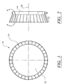
- a turbine spring clip seal 10 can be configured as a generally cylindrical- or ring-shaped assembly, including an outer housing 14 and an inner housing 16.
- a turbine spring clip seal 10, such as one according to the invention, is usable in turbine engines to direct gases to mix with fuel flowing into a conventional combustor basket 12 (see FIG. 8).
- the spring clip seal is intended to direct fluid flow and to prevent at least a portion of air directed through the center aperture 50 in the turbine spring seal from leaking between the inner and outer housings 14 and 16.
- the flow region within the center aperture 50 is relatively higher in pressure than the region outside housing 14, so that fluid leakage generally occurs from the inside out.
- the sealing capabilities of the seal 10 are improved through the use of a center sealing member.
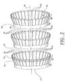
- the turbine spring clip seal 10 is formed from an outer housing 14, an inner housing 16 and, according to the invention, a center sealing member 18.
- the outer and inner housings 14 and 16 have the same general configuration, and the outer housing 14 is sized to receive the inner housing 16 in nested fashion.
- the center sealing member 18 can also be constructed as a ring and nests with the outer housing 14, while the inner housing 16 nests within the center sealing member 18.
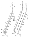
- the outer housing 14 provides an outer coupler section 20 and an outer transition section 22 extending therefrom.
- the outer housing 14 may have a configuration resembling a conventional reducer and have a generally conical shape, although alternative geometries are considered within the scope of the invention.
- the outer coupler section 20 may be in the shape of a ring and is configured to be fixedly attached to a turbine component using for instance, a weld bond.
- the outer coupler section 20 is fixedly attached to a combustor basket 12 (see FIG. 8).
- the outer transition section 22 has a general conical shape for deflecting air toward the center opening of the transition section 22 during operation.
- the outer housing 14 also may include a plurality of slots 24 that are typically located in the outer transition section 22.
- the slots 24 preferably extend from an edge of the outer transition section 22 into the outer transition section 22 toward the outer coupler section 20.
- the slots 24 may have any length, and in one embodiment, one or more of the slots 24 may extend to the outer coupler section 20. In yet another embodiment, the slots 24 may extend through the width of the transition section 22 and into the coupler section 20. However, the slots 24 should not extend completely through the coupler section 20.
- the plurality of slots 24 may be composed of two or more slots and, in one embodiment, may be composed of thirty-two slots.
- the slots 24 are positioned generally parallel to a longitudinal axis 28 of the turbine spring clip seal 10 and the outer housing 14 and form leaves 30 between adjacent slots 24.
- the leaves 30 are flexible and are capable of deflecting inwardly.
- the outer housing 14 may also include a wear resistant material 34 for reinforcing the turbine spring clip seal 10 at its juncture with a turbine component 32.
- the wear resistant material 34 may be applied to the outer surface 36 of the outer housing 14 in any location that the outer housing 14 contacts a turbine component 34. In one embodiment, the wear resistant material 34 is applied to the outer surface 36 of the outer housing 14 proximate to the edge of the outer transition section 22 and extending about one inch toward the outer coupler section 20. If the outer housing 14 includes slots 24, the wear resistant material 34 is located on the leaves 30 formed by the slots 24.
- the wear resistant material 34 is composed of chromium carbide and is spray applied.
- the wear resistant material 34 and the method of application are not limited to this material or method. Rather, the wear resistant material 34 may consist of other materials capable of withstanding the hot environment of a turbine engine and may be applied using application methods such as, but not limited to, dipping, anodizing, and other methods.
- the outside diameter of the outer housing 14 is slightly greater than the inside diameter of the turbine component 32 in which the turbine spring clip seal 10 is positioned (see FIG. 8). Such a configuration forms an interference fit with the turbine component 32 and is useful to form an airtight seal.
- the turbine component 32 is a transition inlet ring.
- the inner housing 16 is substantially similar in configuration to the outer housing 14 and the inner housing 16 includes all of the elements discussed above.
- the inner housing 16 includes an inner coupler section 38 and an inner transition section 40 extending therefrom.
- the inner transition section 40 may include a plurality of slots 42, numbering two or more, that may be generally parallel to the longitudinal axis 28 of the turbine spring clip seal 10 and the inner housing 16.
- the inner coupler section 38 of the inner housing 16 is configured to be attached to the outer coupler section 20 of the outer housing 14, and the inner housing 16 is configured to fit inside the outer housing 14.
- the inner and outer housing 14 and 16 may be formed from any high strength and high temperature material, such as, but not limited to, X750 or a nickel based material.
- the inner and outer housings 14 and 16 may each have a thickness of about 0.050 of an inch. However, the thickness of the inner and outer housings 14 and 16 are not limited to this thickness. Rather, the thickness may vary depending on the material used in order to maintain the flexibility of the turbine spring clip seal 10.
- the turbine spring clip seal 10 further includes a center sealing member 18 sized and configured to fit between the inner and outer housings 14 and 16.
- the center sealing member 18 generally has a shape similar to the shape of the inner and outer housings 14 and 16, and in one embodiment, may be substantially identical to the inner and outer housings 14 and 16.
- the center sealing member 18 is flexible so that during operation of a turbine in which the seal 10 is positioned, the pressure drop between the relatively higher pressure within the center aperture 50 and the relatively lower region outside the outer housing 14, as discussed above, causes the center sealing member 18 to be drawn against the outer housing 14.
- the center sealing member 18 may be formed from a metal, such as, but not limited to, a 300 series stainless steel or a nickel based sheet material, having a thickness between about 0.004 of an inch and about 0.015 of an inch. It is evident to those of ordinary skill in the art that the thickness of the material will vary depending on the strength of the material used to form the center sealing member 18. Thus, the various thicknesses for alternative materials are not discussed.
- a metal such as, but not limited to, a 300 series stainless steel or a nickel based sheet material
- the center sealing member 18 may also include a plurality of slots 44 positioned around the outer perimeter 46 in a configuration similar to the configuration of slots in the inner and outer housings 14 and 16. In one embodiment, the slots 44 are equally spaced. The slots 44 provide increased flexibility to the perimeter 46 of the center sealing member 18 by providing a series of flexible leaves 48.
- the center sealing member when the turbine spring clip seal 10 is fully assembled, the center sealing member is oriented relative to the outer housing so that the leaves of the center sealing member cover the slots 24 in the outer housing 14, as shown in FIG. 6.
- the slots 44 in the center sealing member 18 are not aligned with the slots 24 in the outer housing 14.
- a fluid such as, but not limited to, common air, does not have a direct flow path through the turbine spring clip seal 10.
- the slots 42 in the inner housing 16 are typically aligned with the slots 44 in a center sealing member 18, and the slots 24 in the outer housing 14 are misaligned with the slots 44 in the center sealing member 18 and the slots 42 of the inner housing.
- the slots 42 in the inner housing 16 are misaligned with the slots 44 in the center sealing member 18, and the slots 24 in the outer housing 14 are misaligned with the 44 slots in the center sealing member 18.
Landscapes
- Engineering & Computer Science (AREA)
- Chemical & Material Sciences (AREA)
- Combustion & Propulsion (AREA)
- Mechanical Engineering (AREA)
- General Engineering & Computer Science (AREA)
- Gasket Seals (AREA)
- Turbine Rotor Nozzle Sealing (AREA)
Applications Claiming Priority (2)
| Application Number | Priority Date | Filing Date | Title |
|---|---|---|---|
| US10/255,896 US7093837B2 (en) | 2002-09-26 | 2002-09-26 | Turbine spring clip seal |
| US255896 | 2002-09-26 |
Publications (2)
| Publication Number | Publication Date |
|---|---|
| EP1403584A1 true EP1403584A1 (de) | 2004-03-31 |
| EP1403584B1 EP1403584B1 (de) | 2016-04-13 |
Family
ID=31977853
Family Applications (1)
| Application Number | Title | Priority Date | Filing Date |
|---|---|---|---|
| EP03077778.3A Expired - Lifetime EP1403584B1 (de) | 2002-09-26 | 2003-09-03 | Turbinenfederklammerdichtung |
Country Status (2)
| Country | Link |
|---|---|
| US (1) | US7093837B2 (de) |
| EP (1) | EP1403584B1 (de) |
Cited By (2)
| Publication number | Priority date | Publication date | Assignee | Title |
|---|---|---|---|---|
| US7421842B2 (en) * | 2005-07-18 | 2008-09-09 | Siemens Power Generation, Inc. | Turbine spring clip seal |
| EP1571396A3 (de) * | 2004-03-01 | 2013-07-24 | Alstom Technology Ltd | Dichtungskörper bei einer Brennkamer einer Gasturbine |
Families Citing this family (8)
| Publication number | Priority date | Publication date | Assignee | Title |
|---|---|---|---|---|
| US20060230763A1 (en) * | 2005-04-13 | 2006-10-19 | General Electric Company | Combustor and cap assemblies for combustors in a gas turbine |
| GB0724122D0 (en) * | 2007-12-11 | 2008-01-23 | Rubberatkins Ltd | Sealing apparatus |
| US8627669B2 (en) * | 2008-07-18 | 2014-01-14 | Siemens Energy, Inc. | Elimination of plate fins in combustion baskets by CMC insulation installed by shrink fit |
| US9404580B2 (en) * | 2012-04-13 | 2016-08-02 | United Technologies Corporation | Duplex finger seal for joints with high relative displacement |
| US9416969B2 (en) | 2013-03-14 | 2016-08-16 | Siemens Aktiengesellschaft | Gas turbine transition inlet ring adapter |
| US20150316011A1 (en) * | 2014-05-05 | 2015-11-05 | Electro-Motive Diesel, Inc. | Sealing body for isolating vibrations from cylinder body to nozzle |
| EP2947282B1 (de) * | 2014-05-19 | 2016-10-05 | MTU Aero Engines GmbH | Zwischengehäuse für eine Gasturbine sowie Gasturbine |
| US20170051983A1 (en) * | 2015-08-18 | 2017-02-23 | Arvos Inc. | Flexible seal for a rotary regenerative preheater |
Citations (4)
| Publication number | Priority date | Publication date | Assignee | Title |
|---|---|---|---|---|
| US3759038A (en) * | 1971-12-09 | 1973-09-18 | Westinghouse Electric Corp | Self aligning combustor and transition structure for a gas turbine |
| GB2247521A (en) * | 1990-09-01 | 1992-03-04 | Rolls Royce Plc | A combustion chamber assembly |
| EP0875721A1 (de) * | 1996-01-17 | 1998-11-04 | Mitsubishi Jukogyo Kabushiki Kaisha | Federude dichtung für eine brennkammer |
| WO2002068843A2 (en) * | 2001-02-23 | 2002-09-06 | Grondahl Clayton M | Seal assembly and rotary machine containing such seal |
Family Cites Families (26)
| Publication number | Priority date | Publication date | Assignee | Title |
|---|---|---|---|---|
| US2124108A (en) * | 1937-01-09 | 1938-07-19 | Harry H Grece | Lubricated dust guard |
| US3144255A (en) * | 1961-07-14 | 1964-08-11 | Gen Electric | Sealing means utilizing leaf members |
| RO61044A (fr) | 1971-05-11 | 1977-10-15 | Gelenkwellenbau Gmbh | Etanchement interieur pour articulation |
| US3938906A (en) | 1974-10-07 | 1976-02-17 | Westinghouse Electric Corporation | Slidable stator seal |
| CH613274A5 (de) * | 1976-11-17 | 1979-09-14 | Sulzer Ag | |
| US4184689A (en) | 1978-10-02 | 1980-01-22 | United Technologies Corporation | Seal structure for an axial flow rotary machine |
| US4314793A (en) | 1978-12-20 | 1982-02-09 | United Technologies Corporation | Temperature actuated turbine seal |
| US4413470A (en) * | 1981-03-05 | 1983-11-08 | Electric Power Research Institute, Inc. | Catalytic combustion system for a stationary combustion turbine having a transition duct mounted catalytic element |
| US4527397A (en) * | 1981-03-27 | 1985-07-09 | Westinghouse Electric Corp. | Turbine combustor having enhanced wall cooling for longer combustor life at high combustor outlet gas temperatures |
| US4376542A (en) | 1981-07-29 | 1983-03-15 | Hennessy Products, Incorporated | Hopper door gasket structure |
| GB2167140B (en) * | 1984-10-17 | 1987-10-28 | Terence Peter Nicholson | Shaft or butterfly valve seal |
| US4645217A (en) * | 1985-11-29 | 1987-02-24 | United Technologies Corporation | Finger seal assembly |
| US4785623A (en) | 1987-12-09 | 1988-11-22 | United Technologies Corporation | Combustor seal and support |
| US4811961A (en) * | 1988-04-08 | 1989-03-14 | Boliden Allis, Inc. | Seal for rotating cylinders such as kilns and the like |
| US4961588A (en) * | 1989-01-31 | 1990-10-09 | Westinghouse Electric Corp. | Radial seal |
| US5118120A (en) | 1989-07-10 | 1992-06-02 | General Electric Company | Leaf seals |
| US5100158A (en) * | 1990-08-16 | 1992-03-31 | Eg&G Sealol, Inc. | Compliant finer seal |
| JP2785087B2 (ja) * | 1991-07-12 | 1998-08-13 | プラクセア・エス・ティー・テクノロジー・インコーポレイテッド | 炭化クロム−時効硬化性ニッケル基合金を被覆した回転シール部材 |
| US5361577A (en) * | 1991-07-15 | 1994-11-08 | General Electric Company | Spring loaded cross-fire tube |
| US5400586A (en) | 1992-07-28 | 1995-03-28 | General Electric Co. | Self-accommodating brush seal for gas turbine combustor |
| US5797723A (en) | 1996-11-13 | 1998-08-25 | General Electric Company | Turbine flowpath seal |
| US6076835A (en) | 1997-05-21 | 2000-06-20 | Allison Advanced Development Company | Interstage van seal apparatus |
| US6065756A (en) * | 1997-12-10 | 2000-05-23 | General Electric Co. | Flex seal for gas turbine expansion joints |
| US6164656A (en) | 1999-01-29 | 2000-12-26 | General Electric Company | Turbine nozzle interface seal and methods |
| US6402466B1 (en) | 2000-05-16 | 2002-06-11 | General Electric Company | Leaf seal for gas turbine stator shrouds and a nozzle band |
| JP2002363770A (ja) * | 2001-06-06 | 2002-12-18 | Exedy Corp | ダイヤフラムスプリングの支点部分及びそれと摺動する板材の表面処理方法 |
-
2002
- 2002-09-26 US US10/255,896 patent/US7093837B2/en not_active Expired - Lifetime
-
2003
- 2003-09-03 EP EP03077778.3A patent/EP1403584B1/de not_active Expired - Lifetime
Patent Citations (4)
| Publication number | Priority date | Publication date | Assignee | Title |
|---|---|---|---|---|
| US3759038A (en) * | 1971-12-09 | 1973-09-18 | Westinghouse Electric Corp | Self aligning combustor and transition structure for a gas turbine |
| GB2247521A (en) * | 1990-09-01 | 1992-03-04 | Rolls Royce Plc | A combustion chamber assembly |
| EP0875721A1 (de) * | 1996-01-17 | 1998-11-04 | Mitsubishi Jukogyo Kabushiki Kaisha | Federude dichtung für eine brennkammer |
| WO2002068843A2 (en) * | 2001-02-23 | 2002-09-06 | Grondahl Clayton M | Seal assembly and rotary machine containing such seal |
Cited By (2)
| Publication number | Priority date | Publication date | Assignee | Title |
|---|---|---|---|---|
| EP1571396A3 (de) * | 2004-03-01 | 2013-07-24 | Alstom Technology Ltd | Dichtungskörper bei einer Brennkamer einer Gasturbine |
| US7421842B2 (en) * | 2005-07-18 | 2008-09-09 | Siemens Power Generation, Inc. | Turbine spring clip seal |
Also Published As
| Publication number | Publication date |
|---|---|
| US7093837B2 (en) | 2006-08-22 |
| EP1403584B1 (de) | 2016-04-13 |
| US20050062237A1 (en) | 2005-03-24 |
Similar Documents
| Publication | Publication Date | Title |
|---|---|---|
| US6869082B2 (en) | Turbine spring clip seal | |
| EP2813761B1 (de) | Aerodynamische Vorrichtung zur Verbesserung der Seitenteilkühlung eines prallgekühlten Turbineneinlasskanales und Verfahren dafür | |
| US7788932B2 (en) | Seal structure for gas turbine combustor | |
| US6883807B2 (en) | Multidirectional turbine shim seal | |
| CA2046796C (en) | Combustor dome assembly | |
| US7600970B2 (en) | Ceramic matrix composite vane seals | |
| US7246995B2 (en) | Seal usable between a transition and a turbine vane assembly in a turbine engine | |
| KR100476353B1 (ko) | 압축기배출디퓨저및가스터빈 | |
| WO1998053228A1 (en) | Interstage vane seal apparatus | |
| US7784264B2 (en) | Slidable spring-loaded transition-to-turbine seal apparatus and heat-shielding system, comprising the seal, at transition/turbine junction of a gas turbine engine | |
| JP4559796B2 (ja) | 自由浮動スワーラを有するガスタービンエンジンの燃焼器ドーム組立体 | |
| US4693074A (en) | Combustion apparatus for a gas turbine engine | |
| US7093837B2 (en) | Turbine spring clip seal | |
| EP2105582A2 (de) | Gasturbinendichtungsanordnung sowie Gasturbine mit einer solchen Dichtungsanordnung | |
| US7131273B2 (en) | Gas turbine engine carburetor with flat retainer connecting primary and secondary swirlers | |
| CA2615296C (en) | Turbine spring clip seal | |
| JP5149596B2 (ja) | 燃焼器ドームミキサー保持手段 | |
| KR20220014301A (ko) | 냉각 튜브를 구비한 충돌 플레이트를 갖는 연소기 캡 조립체 | |
| GB2267319A (en) | Sealing components in turbine engines. | |
| US5085039A (en) | Coanda phenomena combustor for a turbine engine | |
| CN103573416B (zh) | 密封件 | |
| CN112513530B (zh) | 用于涡轮机的组合件 | |
| US9291102B2 (en) | Interface ring for gas turbine fuel nozzle assemblies | |
| US8590864B2 (en) | Semi-tubular vane air swirler | |
| EP1840461A1 (de) | Gasbrennerendkappe |
Legal Events
| Date | Code | Title | Description |
|---|---|---|---|
| PUAI | Public reference made under article 153(3) epc to a published international application that has entered the european phase |
Free format text: ORIGINAL CODE: 0009012 |
|
| AK | Designated contracting states |
Kind code of ref document: A1 Designated state(s): AT BE BG CH CY CZ DE DK EE ES FI FR GB GR HU IE IT LI LU MC NL PT RO SE SI SK TR |
|
| AX | Request for extension of the european patent |
Extension state: AL LT LV MK |
|
| 17P | Request for examination filed |
Effective date: 20040422 |
|
| AKX | Designation fees paid |
Designated state(s): DE FR GB IT |
|
| RAP1 | Party data changed (applicant data changed or rights of an application transferred) |
Owner name: SIEMENS POWER GENERATION, INC. |
|
| RAP1 | Party data changed (applicant data changed or rights of an application transferred) |
Owner name: SIEMENS ENERGY, INC. |
|
| 17Q | First examination report despatched |
Effective date: 20090710 |
|
| R17C | First examination report despatched (corrected) |
Effective date: 20100318 |
|
| GRAP | Despatch of communication of intention to grant a patent |
Free format text: ORIGINAL CODE: EPIDOSNIGR1 |
|
| INTG | Intention to grant announced |
Effective date: 20151103 |
|
| GRAS | Grant fee paid |
Free format text: ORIGINAL CODE: EPIDOSNIGR3 |
|
| GRAA | (expected) grant |
Free format text: ORIGINAL CODE: 0009210 |
|
| AK | Designated contracting states |
Kind code of ref document: B1 Designated state(s): DE FR GB IT |
|
| REG | Reference to a national code |
Ref country code: GB Ref legal event code: FG4D |
|
| REG | Reference to a national code |
Ref country code: DE Ref legal event code: R096 Ref document number: 60348790 Country of ref document: DE |
|
| PG25 | Lapsed in a contracting state [announced via postgrant information from national office to epo] |
Ref country code: IT Free format text: LAPSE BECAUSE OF FAILURE TO SUBMIT A TRANSLATION OF THE DESCRIPTION OR TO PAY THE FEE WITHIN THE PRESCRIBED TIME-LIMIT Effective date: 20160413 |
|
| REG | Reference to a national code |
Ref country code: DE Ref legal event code: R097 Ref document number: 60348790 Country of ref document: DE |
|
| PLBE | No opposition filed within time limit |
Free format text: ORIGINAL CODE: 0009261 |
|
| STAA | Information on the status of an ep patent application or granted ep patent |
Free format text: STATUS: NO OPPOSITION FILED WITHIN TIME LIMIT |
|
| 26N | No opposition filed |
Effective date: 20170116 |
|
| REG | Reference to a national code |
Ref country code: DE Ref legal event code: R119 Ref document number: 60348790 Country of ref document: DE |
|
| GBPC | Gb: european patent ceased through non-payment of renewal fee |
Effective date: 20160903 |
|
| REG | Reference to a national code |
Ref country code: FR Ref legal event code: ST Effective date: 20170531 |
|
| PG25 | Lapsed in a contracting state [announced via postgrant information from national office to epo] |
Ref country code: GB Free format text: LAPSE BECAUSE OF NON-PAYMENT OF DUE FEES Effective date: 20160903 Ref country code: FR Free format text: LAPSE BECAUSE OF NON-PAYMENT OF DUE FEES Effective date: 20160930 Ref country code: DE Free format text: LAPSE BECAUSE OF NON-PAYMENT OF DUE FEES Effective date: 20170401 |