EP1403528A1 - Hydraulic circuit device - Google Patents
Hydraulic circuit device Download PDFInfo
- Publication number
- EP1403528A1 EP1403528A1 EP02738707A EP02738707A EP1403528A1 EP 1403528 A1 EP1403528 A1 EP 1403528A1 EP 02738707 A EP02738707 A EP 02738707A EP 02738707 A EP02738707 A EP 02738707A EP 1403528 A1 EP1403528 A1 EP 1403528A1
- Authority
- EP
- European Patent Office
- Prior art keywords
- valve
- pressure
- supply
- electromagnetic proportional
- flowrate
- Prior art date
- Legal status (The legal status is an assumption and is not a legal conclusion. Google has not performed a legal analysis and makes no representation as to the accuracy of the status listed.)
- Withdrawn
Links
Images




Classifications
-
- F—MECHANICAL ENGINEERING; LIGHTING; HEATING; WEAPONS; BLASTING
- F15—FLUID-PRESSURE ACTUATORS; HYDRAULICS OR PNEUMATICS IN GENERAL
- F15B—SYSTEMS ACTING BY MEANS OF FLUIDS IN GENERAL; FLUID-PRESSURE ACTUATORS, e.g. SERVOMOTORS; DETAILS OF FLUID-PRESSURE SYSTEMS, NOT OTHERWISE PROVIDED FOR
- F15B21/00—Common features of fluid actuator systems; Fluid-pressure actuator systems or details thereof, not covered by any other group of this subclass
- F15B21/08—Servomotor systems incorporating electrically operated control means
- F15B21/087—Control strategy, e.g. with block diagram
-
- F—MECHANICAL ENGINEERING; LIGHTING; HEATING; WEAPONS; BLASTING
- F15—FLUID-PRESSURE ACTUATORS; HYDRAULICS OR PNEUMATICS IN GENERAL
- F15B—SYSTEMS ACTING BY MEANS OF FLUIDS IN GENERAL; FLUID-PRESSURE ACTUATORS, e.g. SERVOMOTORS; DETAILS OF FLUID-PRESSURE SYSTEMS, NOT OTHERWISE PROVIDED FOR
- F15B9/00—Servomotors with follow-up action, e.g. obtained by feed-back control, i.e. in which the position of the actuated member conforms with that of the controlling member
- F15B9/02—Servomotors with follow-up action, e.g. obtained by feed-back control, i.e. in which the position of the actuated member conforms with that of the controlling member with servomotors of the reciprocatable or oscillatable type
- F15B9/03—Servomotors with follow-up action, e.g. obtained by feed-back control, i.e. in which the position of the actuated member conforms with that of the controlling member with servomotors of the reciprocatable or oscillatable type with electrical control means
-
- F—MECHANICAL ENGINEERING; LIGHTING; HEATING; WEAPONS; BLASTING
- F04—POSITIVE - DISPLACEMENT MACHINES FOR LIQUIDS; PUMPS FOR LIQUIDS OR ELASTIC FLUIDS
- F04B—POSITIVE-DISPLACEMENT MACHINES FOR LIQUIDS; PUMPS
- F04B49/00—Control, e.g. of pump delivery, or pump pressure of, or safety measures for, machines, pumps, or pumping installations, not otherwise provided for, or of interest apart from, groups F04B1/00 - F04B47/00
- F04B49/02—Stopping, starting, unloading or idling control
- F04B49/022—Stopping, starting, unloading or idling control by means of pressure
-
- F—MECHANICAL ENGINEERING; LIGHTING; HEATING; WEAPONS; BLASTING
- F15—FLUID-PRESSURE ACTUATORS; HYDRAULICS OR PNEUMATICS IN GENERAL
- F15B—SYSTEMS ACTING BY MEANS OF FLUIDS IN GENERAL; FLUID-PRESSURE ACTUATORS, e.g. SERVOMOTORS; DETAILS OF FLUID-PRESSURE SYSTEMS, NOT OTHERWISE PROVIDED FOR
- F15B11/00—Servomotor systems without provision for follow-up action ; Circuits therefor
- F15B11/16—Servomotor systems without provision for follow-up action ; Circuits therefor with two or more servomotors
- F15B11/161—Servomotor systems without provision for follow-up action ; Circuits therefor with two or more servomotors with sensing of servomotor demand or load
- F15B11/165—Servomotor systems without provision for follow-up action ; Circuits therefor with two or more servomotors with sensing of servomotor demand or load for adjusting the pump output or bypass in response to demand
-
- F—MECHANICAL ENGINEERING; LIGHTING; HEATING; WEAPONS; BLASTING
- F04—POSITIVE - DISPLACEMENT MACHINES FOR LIQUIDS; PUMPS FOR LIQUIDS OR ELASTIC FLUIDS
- F04B—POSITIVE-DISPLACEMENT MACHINES FOR LIQUIDS; PUMPS
- F04B2205/00—Fluid parameters
- F04B2205/05—Pressure after the pump outlet
-
- F—MECHANICAL ENGINEERING; LIGHTING; HEATING; WEAPONS; BLASTING
- F15—FLUID-PRESSURE ACTUATORS; HYDRAULICS OR PNEUMATICS IN GENERAL
- F15B—SYSTEMS ACTING BY MEANS OF FLUIDS IN GENERAL; FLUID-PRESSURE ACTUATORS, e.g. SERVOMOTORS; DETAILS OF FLUID-PRESSURE SYSTEMS, NOT OTHERWISE PROVIDED FOR
- F15B2211/00—Circuits for servomotor systems
- F15B2211/20—Fluid pressure source, e.g. accumulator or variable axial piston pump
- F15B2211/205—Systems with pumps
- F15B2211/2053—Type of pump
- F15B2211/20538—Type of pump constant capacity
-
- F—MECHANICAL ENGINEERING; LIGHTING; HEATING; WEAPONS; BLASTING
- F15—FLUID-PRESSURE ACTUATORS; HYDRAULICS OR PNEUMATICS IN GENERAL
- F15B—SYSTEMS ACTING BY MEANS OF FLUIDS IN GENERAL; FLUID-PRESSURE ACTUATORS, e.g. SERVOMOTORS; DETAILS OF FLUID-PRESSURE SYSTEMS, NOT OTHERWISE PROVIDED FOR
- F15B2211/00—Circuits for servomotor systems
- F15B2211/40—Flow control
- F15B2211/405—Flow control characterised by the type of flow control means or valve
- F15B2211/40515—Flow control characterised by the type of flow control means or valve with variable throttles or orifices
-
- F—MECHANICAL ENGINEERING; LIGHTING; HEATING; WEAPONS; BLASTING
- F15—FLUID-PRESSURE ACTUATORS; HYDRAULICS OR PNEUMATICS IN GENERAL
- F15B—SYSTEMS ACTING BY MEANS OF FLUIDS IN GENERAL; FLUID-PRESSURE ACTUATORS, e.g. SERVOMOTORS; DETAILS OF FLUID-PRESSURE SYSTEMS, NOT OTHERWISE PROVIDED FOR
- F15B2211/00—Circuits for servomotor systems
- F15B2211/40—Flow control
- F15B2211/405—Flow control characterised by the type of flow control means or valve
- F15B2211/40553—Flow control characterised by the type of flow control means or valve with pressure compensating valves
-
- F—MECHANICAL ENGINEERING; LIGHTING; HEATING; WEAPONS; BLASTING
- F15—FLUID-PRESSURE ACTUATORS; HYDRAULICS OR PNEUMATICS IN GENERAL
- F15B—SYSTEMS ACTING BY MEANS OF FLUIDS IN GENERAL; FLUID-PRESSURE ACTUATORS, e.g. SERVOMOTORS; DETAILS OF FLUID-PRESSURE SYSTEMS, NOT OTHERWISE PROVIDED FOR
- F15B2211/00—Circuits for servomotor systems
- F15B2211/40—Flow control
- F15B2211/41—Flow control characterised by the positions of the valve element
- F15B2211/413—Flow control characterised by the positions of the valve element the positions being continuously variable, e.g. as realised by proportional valves
-
- F—MECHANICAL ENGINEERING; LIGHTING; HEATING; WEAPONS; BLASTING
- F15—FLUID-PRESSURE ACTUATORS; HYDRAULICS OR PNEUMATICS IN GENERAL
- F15B—SYSTEMS ACTING BY MEANS OF FLUIDS IN GENERAL; FLUID-PRESSURE ACTUATORS, e.g. SERVOMOTORS; DETAILS OF FLUID-PRESSURE SYSTEMS, NOT OTHERWISE PROVIDED FOR
- F15B2211/00—Circuits for servomotor systems
- F15B2211/40—Flow control
- F15B2211/415—Flow control characterised by the connections of the flow control means in the circuit
- F15B2211/41581—Flow control characterised by the connections of the flow control means in the circuit being connected to an output member and a return line
-
- F—MECHANICAL ENGINEERING; LIGHTING; HEATING; WEAPONS; BLASTING
- F15—FLUID-PRESSURE ACTUATORS; HYDRAULICS OR PNEUMATICS IN GENERAL
- F15B—SYSTEMS ACTING BY MEANS OF FLUIDS IN GENERAL; FLUID-PRESSURE ACTUATORS, e.g. SERVOMOTORS; DETAILS OF FLUID-PRESSURE SYSTEMS, NOT OTHERWISE PROVIDED FOR
- F15B2211/00—Circuits for servomotor systems
- F15B2211/40—Flow control
- F15B2211/42—Flow control characterised by the type of actuation
- F15B2211/426—Flow control characterised by the type of actuation electrically or electronically
-
- F—MECHANICAL ENGINEERING; LIGHTING; HEATING; WEAPONS; BLASTING
- F15—FLUID-PRESSURE ACTUATORS; HYDRAULICS OR PNEUMATICS IN GENERAL
- F15B—SYSTEMS ACTING BY MEANS OF FLUIDS IN GENERAL; FLUID-PRESSURE ACTUATORS, e.g. SERVOMOTORS; DETAILS OF FLUID-PRESSURE SYSTEMS, NOT OTHERWISE PROVIDED FOR
- F15B2211/00—Circuits for servomotor systems
- F15B2211/50—Pressure control
- F15B2211/505—Pressure control characterised by the type of pressure control means
- F15B2211/50563—Pressure control characterised by the type of pressure control means the pressure control means controlling a differential pressure
- F15B2211/50572—Pressure control characterised by the type of pressure control means the pressure control means controlling a differential pressure using a pressure compensating valve for controlling the pressure difference across a flow control valve
-
- F—MECHANICAL ENGINEERING; LIGHTING; HEATING; WEAPONS; BLASTING
- F15—FLUID-PRESSURE ACTUATORS; HYDRAULICS OR PNEUMATICS IN GENERAL
- F15B—SYSTEMS ACTING BY MEANS OF FLUIDS IN GENERAL; FLUID-PRESSURE ACTUATORS, e.g. SERVOMOTORS; DETAILS OF FLUID-PRESSURE SYSTEMS, NOT OTHERWISE PROVIDED FOR
- F15B2211/00—Circuits for servomotor systems
- F15B2211/50—Pressure control
- F15B2211/515—Pressure control characterised by the connections of the pressure control means in the circuit
- F15B2211/5157—Pressure control characterised by the connections of the pressure control means in the circuit being connected to a pressure source and a return line
-
- F—MECHANICAL ENGINEERING; LIGHTING; HEATING; WEAPONS; BLASTING
- F15—FLUID-PRESSURE ACTUATORS; HYDRAULICS OR PNEUMATICS IN GENERAL
- F15B—SYSTEMS ACTING BY MEANS OF FLUIDS IN GENERAL; FLUID-PRESSURE ACTUATORS, e.g. SERVOMOTORS; DETAILS OF FLUID-PRESSURE SYSTEMS, NOT OTHERWISE PROVIDED FOR
- F15B2211/00—Circuits for servomotor systems
- F15B2211/50—Pressure control
- F15B2211/52—Pressure control characterised by the type of actuation
- F15B2211/528—Pressure control characterised by the type of actuation actuated by fluid pressure
-
- F—MECHANICAL ENGINEERING; LIGHTING; HEATING; WEAPONS; BLASTING
- F15—FLUID-PRESSURE ACTUATORS; HYDRAULICS OR PNEUMATICS IN GENERAL
- F15B—SYSTEMS ACTING BY MEANS OF FLUIDS IN GENERAL; FLUID-PRESSURE ACTUATORS, e.g. SERVOMOTORS; DETAILS OF FLUID-PRESSURE SYSTEMS, NOT OTHERWISE PROVIDED FOR
- F15B2211/00—Circuits for servomotor systems
- F15B2211/60—Circuit components or control therefor
- F15B2211/605—Load sensing circuits
-
- F—MECHANICAL ENGINEERING; LIGHTING; HEATING; WEAPONS; BLASTING
- F15—FLUID-PRESSURE ACTUATORS; HYDRAULICS OR PNEUMATICS IN GENERAL
- F15B—SYSTEMS ACTING BY MEANS OF FLUIDS IN GENERAL; FLUID-PRESSURE ACTUATORS, e.g. SERVOMOTORS; DETAILS OF FLUID-PRESSURE SYSTEMS, NOT OTHERWISE PROVIDED FOR
- F15B2211/00—Circuits for servomotor systems
- F15B2211/60—Circuit components or control therefor
- F15B2211/63—Electronic controllers
- F15B2211/6303—Electronic controllers using input signals
- F15B2211/6306—Electronic controllers using input signals representing a pressure
- F15B2211/6309—Electronic controllers using input signals representing a pressure the pressure being a pressure source supply pressure
-
- F—MECHANICAL ENGINEERING; LIGHTING; HEATING; WEAPONS; BLASTING
- F15—FLUID-PRESSURE ACTUATORS; HYDRAULICS OR PNEUMATICS IN GENERAL
- F15B—SYSTEMS ACTING BY MEANS OF FLUIDS IN GENERAL; FLUID-PRESSURE ACTUATORS, e.g. SERVOMOTORS; DETAILS OF FLUID-PRESSURE SYSTEMS, NOT OTHERWISE PROVIDED FOR
- F15B2211/00—Circuits for servomotor systems
- F15B2211/60—Circuit components or control therefor
- F15B2211/63—Electronic controllers
- F15B2211/6303—Electronic controllers using input signals
- F15B2211/632—Electronic controllers using input signals representing a flow rate
- F15B2211/6323—Electronic controllers using input signals representing a flow rate the flow rate being a pressure source flow rate
-
- F—MECHANICAL ENGINEERING; LIGHTING; HEATING; WEAPONS; BLASTING
- F15—FLUID-PRESSURE ACTUATORS; HYDRAULICS OR PNEUMATICS IN GENERAL
- F15B—SYSTEMS ACTING BY MEANS OF FLUIDS IN GENERAL; FLUID-PRESSURE ACTUATORS, e.g. SERVOMOTORS; DETAILS OF FLUID-PRESSURE SYSTEMS, NOT OTHERWISE PROVIDED FOR
- F15B2211/00—Circuits for servomotor systems
- F15B2211/60—Circuit components or control therefor
- F15B2211/665—Methods of control using electronic components
- F15B2211/6655—Power control, e.g. combined pressure and flow rate control
-
- F—MECHANICAL ENGINEERING; LIGHTING; HEATING; WEAPONS; BLASTING
- F15—FLUID-PRESSURE ACTUATORS; HYDRAULICS OR PNEUMATICS IN GENERAL
- F15B—SYSTEMS ACTING BY MEANS OF FLUIDS IN GENERAL; FLUID-PRESSURE ACTUATORS, e.g. SERVOMOTORS; DETAILS OF FLUID-PRESSURE SYSTEMS, NOT OTHERWISE PROVIDED FOR
- F15B2211/00—Circuits for servomotor systems
- F15B2211/60—Circuit components or control therefor
- F15B2211/665—Methods of control using electronic components
- F15B2211/6656—Closed loop control, i.e. control using feedback
Definitions
- the present invention relates in general to a hydraulic circuit system for driving a hydraulic actuator of a mechanical apparatus.
- the present invention pertains in particular to the technical field of controlling the flowrate and the pressure of operating fluid in order to provide correct control of the operating speed and the working force of such a hydraulic actuator.
- an oil hydraulic circuit system housing therein a flowrate electromagnetic proportional valve (hereinafter a flowrate proportional valve) for controlling the flowrate of supply of operating oil to an actuator and a pressure electromagnetic proportional valve (hereinafter a pressure proportional valve) for controlling the pressure of supply of operating oil to the actuator has been known widely in the art.
- a flowrate proportional valve for controlling the flowrate of supply of operating oil to an actuator
- a pressure electromagnetic proportional valve for controlling the pressure of supply of operating oil to the actuator
- a flowrate proportional valve (6) is interposingly disposed in a supply passageway (5) through which operating oil is supplied to an oil hydraulic actuator of an oil hydraulic circuit (1) of a main machine (a mechanical apparatus), as shown in Figure 6 .
- the actuator is connected to a port A of the downstream side of the flowrate proportional valve (6) .
- Connected to a port P of the upstream side of the flowrate proportional valve (6) is for example a fixed displacement pump (3) .
- a differential pressure compensation valve (7) is disposed.
- the differential pressure compensation valve (7) receives a pilot pressure from the upstream side of the flowrate proportional valve (6) and another pilot pressure from the downstream side of the flowrate proportional valve (6) and bypasses operating oil to a port T from an upstream supply passageway (5a) so that the difference in pressure between these pilot pressures is held substantially constant.
- a downstream pilot passageway (15) for guiding a pilot pressure to the differential pressure compensation valve (7) from downstream of the flowrate proportional valve (6) , is provided with an orifice (17) .
- a pressure proportional valve (8) for adjusting the downstream pressure by relieving operating oil therefrom, is connected to the pilot passageway (15) between the orifice (17) and the differential pressure compensation valve (7) .
- the valve travel of the flowrate proportional valve (6) and the valve travel of the pressure proportional valve (8) are controlled by electric current drivers (9, 9) , respectively.
- Such a conventional oil hydraulic circuit system automatically switches between a flowrate control mode of operation and a pressure control mode of operation according to the operating state of the actuator.
- a case in which operating oil is supplied to a main oil hydraulic cylinder will be described.
- the amount of supply of operating oil to the oil hydraulic cylinder is adjusted by controlling the valve travel of the flowrate operational valve (6), to control the operating speed of the oil hydraulic cylinder (FLOWRATE CONTROL MODE).
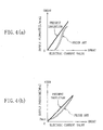
- both the supply flowrate and the supply pressure of operating oil to be supplied to the actuator directly reflect the characteristics of solenoids of the electromagnetic valves (6, 8) . Therefore, variations in the operating oil supply flowrate and pressure with respect to the value of output electric currents from the electric current drivers (9, 9) of the electromagnetic valves (6, 8) are non-linear and hysteretic (see a broken-line graph of Figure 4 ), therefore making it difficult to perform operatiang oil flowrate and pressure control with a high degree of accuracy. Further, owing to such an open control method employing no electric sensor, it is impossible to increase the speed of response with respect to the variation in command value, to a greater extent.
- an object of the present invention is to achieve improvements in the control accuracy and the response of a hydraulic circuit system (2, 20) provided with an electromagnetic proportional valve (6) in a supply passageway (5) through which operating oil (operating fluid) is supplied to a hydraulic actuator, for controlling the supply flowrate and the supply pressure of the operating fluid, and particularly for extending the region of controllable pressure to substantially a zero point by eliminating a minimum controllable limit with respect to the supply hydraulic pressure.
- Another object of the present invention is to provide a valve structure capable of placing a restraint on the increase in costs.
- the present invention provides the following means as solutions to the above-described problems.
- a first invention is directed to a hydraulic circuit system (2, 20) comprising an electromagnetic proportional valve (6) , disposed interposingly in a supply passageway (5) through which operating fluid is supplied to a hydraulic actuator, for adjusting the supply flowrate of operating fluid and a differential pressure compensation valve (7) for receiving a pilot pressure from the upstream side of the electromagnetic proportional valve (6) and a pilot pressure from the downstream side of the electromagnetic proportional valve (6) and for bypassing operating fluid to a tank (4) from a supply passageway (5a) on the upstream side of the electromagnetic proportional valve (6) so that the difference between the pilot pressures is held constant.
- the electromagnetic proportional valve (6) assumes, in addition to a supply position for allowing operating fluid to be supplied to the hydraulic actuator, at least a discharge position for allowing operating fluid to be discharged out of the hydraulic actuator.
- the hydraulic circuit system (2, 20) further comprises; a pressure sensor (10) for detecting the working hydraulic pressure of a supply passageway (5b) on the downstream side of the electromagnetic proportional valve (6) and for outputting an electric signal; a position sensor (11) for detecting the spool position of the electromagnetic proportional valve (6) and for outputting an electric signal; and a controller (12) for receiving an electric signal from the pressure sensor (10) and an electric signal from the position sensor (11) and for feedback controlling the valve travel (the spool position) of the electromagnetic proportional valve (6) so that the supply flowrate and/or the supply hydraulic pressure of operating fluid to be supplied to the hydraulic actuator becomes a control command value.
- a pressure sensor (10) for detecting the working hydraulic pressure of a supply passageway (5b) on the downstream side of the electromagnetic proportional valve (6) and for outputting an electric signal
- a position sensor (11) for detecting the spool position of the electromagnetic proportional valve (6) and for outputting an electric signal
- a controller (12) for receiving an electric signal from the pressure sensor (10)
- the spool position of the electromagnetic proportional valve (6) is controlled by the controller (12) , with the difference in pressure between the upstream and downstream sides of the electromagnetic proportional valve (6) held constant by the function of the differential pressure compensation valve (7) .
- the supply flowrate of operating fluid to be supplied to the actuator is controlled (FLOWRATE CONTROL MODE).
- the position sensor (11) detects the actual spool position of the electromagnetic proportional valve (6) .
- Feedback control is performed based on the result of such position detection. Therefore, the rate of flow of operating fluid is controlled with an extremely high degree of accuracy and response. Since solenoid non-linearity characteristics are absorbed apparently by the feedback control, this makes it possible to not only linearize the flowrate control characteristics of the operating fluid but also eliminate hysteresis.
- the controller (12) performs, based on the detection value, feedback control of the electromagnetic proportional valve (6) (PRESSURE CONTROL MODE).
- the electromagnetic proportional valve (6) is assuming the supply position, the supply flowrate of operating fluid is adjusted by controlling, based on the deviation between a value detected by the pressure sensor (10) and the pressure command value, the valve travel (the spool position) of the electromagnetic proportional valve (6) .
- the discharge amount of operating fluid from the downstream supply passageway (5b) is adjusted by controlling the spool position of the electromagnetic proportional valve (6) .
- the hydraulic pressure of the downstream supply passageway (5b) is maintained at the pressure command value in the end.
- the supply hydraulic pressure of operating fluid to be supplied to the actuator can be reduced to zero by changing the position of the electromagnetic proportional valve (6) to the discharge position for the operating fluid to be discharged out of the actuator.
- the first invention requires the pressure sensor (10) and the position sensor (11) which are components that conventional structures do not require.
- the first invention requires neither a pressure proportional valve (8) nor an electric current driver circuit for the pressure proportional valve (8) . This offsets the increase in costs due to the employment of the electric sensors.
- the controller (12) of the hydraulic circuit system (2, 20) comprises: a flowrate deviation arithmetic part (12b) for finding, based on an electric signal from the position sensor (11) , an actual supply flowrate of operating fluid being supplied to the hydraulic actuator and for performing an arithmetical operation to calculate a flowrate deviation by subtracting the found actual supply flowrate from a flowrate command value; a pressure deviation arithmetic part (12a) for finding, based on an electric signal from the pressure sensor (10) , an actual supply hydraulic pressure of operating fluid being supplied to the hydraulic actuator and for performing an arithmetic operation to calculate a pressure deviation by subtracting the found actual supply hydraulic pressure from a pressure command value; a PQ selecting part (12c) for selecting the smaller of the flowrate deviation and the pressure deviation and for performing, based on the selected deviation, an arithmetic operation to calculate a desired spool position for the electromagnetic proportional valve (6) ; and an electric current driver (12d) for applying an electric current to a solenoid (6
- the flowrate deviation arithmetic part (12b) performs an arithmetic operation to calculate the flow deviation between an actual supply flowrate of operating fluid and a flowrate command value.
- the pressure deviation arithmetic part (12a) performs an arithmetic operation to calculate the pressure deviation between an actual supply pressure of operating fluid and a pressure command value.
- the PQ selecting part (12c) selects the flowrate or the pressure, whichever exceeds the control command value to a further extent than the other.
- the PQ selecting part (12c) selects the flowrate or the pressure, whichever is more approximate to the control command value than the other. In other words, the PQ selecting part (12c) deems the state, in which the flowrate and/or the pressure exceeds the command value, dangerous. Then, the PQ selecting part (12c) determines degrees of danger from the flowrate deviation and from the pressure deviation respectively and selects the flowrate deviation or the pressure deviation, whichever is greater in degree of danger. In this way, the working and effects of the first invention are realized.
- the differential pressure compensation valve (7) of the hydraulic circuit system (2, 20) is provided with a spring member (7b) for energizing a valve element (7a) of the differential pressure compensation valve (7) in the valve-closing direction and receives a pilot pressure which causes the valve element (7a) to move in the valve-closing direction and another pilot pressure which causes the valve element (7a) to move in the valve-opening direction, from the downstream side of the electromagnetic proportional valve (6) and from the upstream side of the electromagnetic proportional valve (6) , respectively.
- a pilot passageway (15) on the downstream side of the electromagnetic proportional valve (6) for guiding a pilot pressure to the differential pressure compensation valve (7) from the downstream side of the electromagnetic proportional valve (6) is provided with an orifice (17) capable of restricting a flow of operating fluid and a pilot relief valve (18) is connected to the pilot passageway (15) between the orifice (17) and the differential pressure compensation valve (7) .
- the pilot relief valve (18) , the differential pressure compensation valve (7) , and the orifice (17) together function as a so-called pilot type relief valve when the hydraulic pressure of the downstream supply passageway (5b) exceeds the set pressure of the pilot relief valve (18) , thereby preventing the increase in hydraulic pressure in the downstream supply passageway (5b) .
- a flow of operating fluid in the downstream pilot passageway (15) receives a pass resistance from the orifice (17) , by which adequate damping is applied to the operation of the valve element (7a) for the purpose of stabilization.
- the operating fluid flows in the direction of the differential pressure compensation valve (7) in the downstream pilot passageway (15) and, as a result, the valve element (7a) of the differential pressure compensation valve (7) is shifted in the valve-closing direction.
- the degree of force trying to place the valve element (7a) in the closed position is just as great as the energizing force of the spring member (7b) and, besides, the operating fluid flow is restricted by the orifice (17) , as described above.
- the closing operation of the valve element (7a) of the differential pressure compensation valve (7) is delayed. This results in a response delay when increasing the flowrate of supply of operating fluid to the electromagnetic proportional valve (6) .
- the hydraulic circuit system (20) of the third invention preferably employs an arrangement in which a first orifice (21) and a second orifice (22) of a greater degree of restriction than that of the first orifice (21) are provided in series in the downstream pilot passageway (15) and a bypass passageway (23) bypassing the second orifice (22) is provided with a check valve (24) which accepts a flow of operating fluid moving toward the differential pressure compensation valve (7) but prevents reversal of the operating fluid flow.
- valve element (7a) of the differential pressure compensation valve (7) since the valve element (7a) of the differential pressure compensation valve (7) is in receipt of an extremely high upstream pilot pressure, the valve element (7a) of the differential pressure compensation valve (7) is sufficiently quickly placed in the open state in spite of the fact that the operating fluid flow is restricted in the downstream pilot passageway (15) . After all, at the time of reducing the supply flowrate of operating fluid, response delay will not be a problem; rather, the stable operation of the differential pressure compensation valve (7) is maintained because the operating fluid flow in the downstream pilot passageway (15) is sufficiently restricted by the second orifice (22) .
- the provision of the orifices (21, 22) in the downstream pilot passageway (15) makes it possible to secure stability by restricting the opening operation of the valve element (7a) of the differential pressure compensation valve (7) to such an extent that its response is not spoiled.
- response can be secured by not restricting the closing operation of the valve element (7a) . Therefore, both the stability and the response of the flowrate of supply of operating fluid to the actuator can be achieved at high level.
- the hydraulic actuator is employed to actuate an injection molding machine.
- the hydraulic circuit system (2, 20) of the first invention achieves improvement in the operating speed and the working force of the actuator, which is extremely effective to the above requirement.
- the first invention makes it possible to considerably improve the quality of molding products.
- the first invention it is possible to perform control, with the pressure of supply of operating fluid to the actuator reduced to zero. Therefore, it is possible to satisfactory cope with requirements in a low pressure clamping process in an injection molding machine. Furthermore, if the supply flowrate of operating fluid is increased with a high degree of response, this not only facilitates the formation of thin molding products by an injection molding machine but also shortens the cycle of molding. In this light, the working and effects of the invention are extremely effective when applied to an injection molding machine.
- the electromagnetic proportional valve (6) is provided interposingly in the supply passageway (5) through which operating fluid is supplied to the hydraulic actuator.
- the differential pressure compensation valve (7) for receiving a pilot pressure from the upstream side of the electromagnetic proportional valve (6) and a pilot pressure from the downstream side of the electromagnetic proportional valve (6) and for bypassing operating fluid from the upstream supply passageway (5a) so that the difference between these two pilot pressures is held constant, is provided.
- the electromagnetic proportional valve (6) further assumes the discharge position for allowing operating fluid to be discharged from the actuator.
- the electromagnetic proportional valve (6) is further provided with the pressure sensor (10) capable of detecting the working hydraulic pressure of the supply passageway (5b) on the downstream side of the electromagnetic proportional valve (6) and the position sensor (11) capable of detecting the spool position of the electromagnetic proportional valve (6) . Since the spool position (valve travel) of the electromagnetic proportional valve (6) is feedback controlled based on output signals from these sensors, this makes it possible to control the supply flowrate and the supply pressure of operating fluid with an extremely high degree of accuracy.
- the present invention eliminates the need for the provision of a pressure proportional valve (8) and its electric current driver circuit which have been required in conventional prior art techniques. This offsets costs increased by the addition of the sensors.
- the electromagnetic proportional valve (6) is feedback controlled according to the actual supply state of operating fluid by the flowrate deviation arithmetic part (12b) , the pressure deviation arithmetic part (12a) , the PQ selecting part (12c) , et cetera, thereby making it possible to satisfactorily obtain the effects of the first invention.
- the downstream pilot passageway (15) for guiding a pilot pressure to the differential pressure compensation valve (7) of the hydraulic circuit system (2, 20) from the downstream side of the electromagnetic proportional valve (6) , is provided with the orifice (17) capable of restricting a flow of operating fluid and the pilot relief valve (18) .
- by applying adequate damping to the valve element (7a) of the differential pressure compensation valve (7) its operation can be stabilized.
- the first orifice (21) and the second orifice (22) having different degrees of restriction are provided in series.
- the passageway (23) bypassing the second orifice (22) of a greater degree of restriction is provided with the check valve (24) .
- the hydraulic circuit system (2, 20) is applied to an injection molding machine.
- This can provide improvement in productivity by shortening the time of cycle. Improvement in the controllability of the operatiang speed and the working force considerably improves the quality of molding products, and the molding of thin molding products is facilitated. Further, it becomes possible to satisfactorily cope with requirements in a low pressure clamping process and cost reduction can be achieved.
- a hydraulic circuit system of the present invention is applied to a servo valve device which drives an oil hydraulic cylinder of an injection molding machine et cetera.
- a pressure/flowrate servo valve device (2) (hereinafter a PQS valve).
- the PQS valve (2) connected to a main oil hydraulic circuit (1) of a main machine such as an injection molding machine, provides a supply of operating oil (operating fluid) to an actuator such an oil hydraulic cylinder and controls the operating speed and the working force of the actuator by adjusting the supply flowrate ( Q ) and the supply pressure ( P ) of the operating oil.
- the PQS valve (2) is provided with a port A connected to the main oil hydraulic circuit (1) , a port P connected to a fixed displacement type pump (3), and ports T and Y each connected to an oil tank (4) .
- An electromagnetic proportional valve (6) for supply flowrate control is disposed interposingly in an operating oil supply passageway (5) between the port P and the port A .
- the PQS valve (2) is further provided with a differential pressure compensation valve (7) .
- the differential pressure compensation valve (7) receives a pilot pressure from a supply passageway (5a) located upstream of the electromagnetic proportional valve (6) and another pilot pressure from a supply passageway (5b) located downstream of the electromagnetic proportional valve (6) and bypasses operating oil to the oil tank (4) from the upstream supply passageway (5a) so that the difference between the pilot pressures is held substantially constant.
- the PQS valve (2) further includes a pressure sensor (10) for detecting the working oil pressure ( P ) of the supply passageway (5b) located downstream of the electromagnetic proportional valve (6) and outputs an electrical signal and a position sensor (11) for detecting the position of a spool (6a) of the electromagnetic proportional valve (6) and outputs an electrical signal. Further, the PQS valve (2) is provided with a controller (12) .
- the controller (12) Upon receipt of output signals from the sensors (10) and (11) , the controller (12) feedback controls the position of the spool (6a) of the electromagnetic proportional valve (6) , i.e., the valve travel of the electromagnetic proportional valve (6) , so that the supply flowrate Q and the supply pressure P of the operating oil which is supplied to the main oil hydraulic circuit (1) become a command value Qi and a command value Pi , respectively.
- the electromagnetic proportional valve (6) has a solenoid (6b) which is actuated by a control signal (electric current) from the controller (12) .
- the position of the spool (6a) is controlled in resistance to press energizing force by a spring (6c) .
- the electromagnetic proportional valve (6) assumes, in a switching manner, the following positions, namely a supply position for allowing operating oil to be supplied to the main machine, a discharge position for allowing operating oil to be discharged out of the main machine side, and a stop position for stopping the supply and discharge of operating oil.
- the electromagnetic proportional valve (6) assumes either the supply or the discharge position, it is arranged such that the pass cross-sectional area of the operating oil in the electromagnetic proportional valve (6) is controlled continuously.
- the spool (6a) is press energized by the spring (6c) toward the right-hand side of the Figure, in other words the spool (6a) is shifted toward the discharge position.
- the electromagnetic proportional valve (6) shuts off the upstream supply passageway (5a) and brings the downstream supply passageway (5b) into communication with a discharge passageway (13) , so that the operating oil of the main machine side is returned to the oil tank (4) .
- the pass cross-sectional area of the returning operating oil is continuously controlled by continuously varying the position of the spool (6a) .
- the electromagnetic proportional valve (6) shuts off the discharge passageway (13) while at the same time bringing the upstream and downstream supply passageways (5a, 5b) of the supply passageway (5) into communication with each other so that operating oil discharged from the pump (3) is delivered to the main machine side.
- the position of the spool (6a) is continuously varied, thereby causing the pass cross-sectional area of the operating oil to continuously vary, and the flowrate Q of supply of operating oil to the main machine side from the pump (3) will be controlled continuously.
- the electromagnetic proportional valve (6) shuts off the upstream and downstream supply passageways (5a, 5b) of the supply passageway (5) and the discharge passageway (13) .
- the position sensor (11) is attached to the electromagnetic proportional valve (6) .
- the position sensor (11) provides an output of zero value.
- the sensor output of positive value increases as the pass cross-sectional area of the operating oil increases by variation in the position of the spool (6a) .
- the sensor output of negative value decreases as the pass cross-sectional area of the operating oil increases by variation in the position of the spool (6a) .
- the differential pressure compensation valve (7) is a relief valve in which a valve element (7a) such as a poppet is energized in the valve-closing direction by a spring (7b) (a spring member).
- the differential pressure compensation valve (7) is disposed in a branch passageway (14) branching off from the upstream supply passageway (5a), thereby causing the branch passageway (14) to bypass the discharge passageway (13) .
- the downstream pilot passageway (15) branching off from the downstream supply passageway (5b) is connected to the same side that the spring (7b) is mounted.
- a downstream pilot pressure is applied, in the valve-closing direction, to the valve element (7a) .
- the hydraulic pressure of the upstream supply passageway (5a) upstream pilot pressure
- the differential pressure compensation valve (7) is placed in the open state when a press force applied to the valve element (7a) by the upstream pilot pressure becomes greater than an energizing force provided by the spring (7b) , in comparison with a press force applied to the valve element (7a) by the downstream pilot pressure, thereby allowing the operating oil in the upstream supply passageway (5a) to be bypassed, through the branch passageway (14) , to the discharge passageway (13) .
- the valve element (7a) is placed in the closed state to interrupt the bypassing of operating oil. As a result, the upstream pilot pressure increases again.
- the difference in pressure between the upstream and downstream sides of the electromagnetic proportional valve (6) is kept substantially constant by repetition of such closing/opening movement of the valve element (7a) .
- the difference in pressure between the upstream and downstream sides of the electromagnetic proportional valve (6) is so compensated in the above-described way as to be kept substantially constant, which provides a constant correlation between the valve travel of the electromagnetic proportional valve (6) by which the upstream supply passageway (5a) and the downstream supply passageway (5b) are communicated together (i.e., the position of the spool (6a) corresponding to the pass cross-sectional area of the operating oil) and the actual supply flowrate of operating oil. This makes it possible to find an actual supply flowrate on the basis of the spool position.
- the downstream pilot passageway (15) is provided with an orifice (17) capable of restricting a flow of operating oil, and a branch passageway (15a) is connected between the orifice (17) and the differential pressure compensation valve (7) .
- the branch passageway (15a) is provided with a safety valve (18a) (a pilot relief valve).
- the safety valve (18) is placed in the open state when the hydraulic pressure of the branch passageway (15a) exceeds the set pressure of the spring, so that the hydraulic pressure of the downstream pilot passageway (15) is relieved through the branch passageway (15a) . This results in the difference in pressure between the sides of the orifice (17) .
- the hydraulic pressure of the downstream pilot passageway (15) drops, thereby placing the differential pressure compensation valve (7) in the open state.
- the differential pressure compensation valve (7) assumes the open state, the operating oil in the supply passageway (5) is discharged to the oil tank (4) through the port T .
- the differential pressure compensation valve (7) has a function of serving as a pilot relief valve capable of releasing hydraulic pressure in cooperation with the safety valve (18) , when the hydraulic pressure of the supply passageway excessively increases.
- the orifice (17) has a circular cross-section with a diameter of for example about 1 mm.
- the orifice (17) restricts a flow of operating oil in the downstream pilot passageway (15) , thereby creating pass resistance.
- adequate damping is given to the opening/closing movement of the valve element (7a) of the differential pressure compensation valve (7) for stabilizing the operation of the differential pressure compensation valve (7) . Therefore, the orifice (17) has a function of suppressing oscillatory reduction of the flowrate and the pressure of operating oil in the supply passageway (5) .
- the controller (12) is a digital controller for reading a control program electronically stored in memory (not shown) at given time intervals with the aid of a CPU and for executing it.
- the controller (12) is made up of a pressure deviation arithmetic part (12a) and a flowrate deviation arithmetic part (12b) .
- the pressure deviation arithmetic part (12a) finds, based on a signal from the pressure sensor (10) , the real pressure P (the actual pressure) of supply of operating oil to the main machine side and then subtracts the value P from the pressure command value Pi (the desired pressure) to perform an arithmetic operation to calculate a pressure deviation.
- the flowrate deviation arithmetic part (12b) finds, based on a signal from the position sensor (11) , the real flowrate Q (an actual flowrate) of supply of operating oil to the main machine side and then subtracts the value Q from the flowrate command value Qi (the desired flowrate) to perform an arithmetic operation to calculate a flowrate deviation.
- the memory of the controller (12) stores a control program capable of softwarily realizing both the function of the pressure deviation arithmetic part (12a) and the function of the flowrate deviation arithmetic part (12b) .
- the controller (12) further comprises a PQ selecting part (12c) .
- the PQ selecting part (12c) makes a comparison between a pressure deviation found by the pressure deviation arithmetic part (12a) and a flowrate deviation found by the flowrate deviation arithmetic part (12b) , selects the smaller of the pressure and flowrate deviations, and calculates, based on the selected deviation, a desired valve travel for the electromagnetic proportional valve (6) , i.e., the position of the spool (6a) , pursuant to a PID control rule.
- an electric current driver circuit (12d) Upon receipt of an output from the PQ selecting part (12c) , an electric current driver circuit (12d) applies an electric current to the solenoid (6b) of the electromagnetic proportional valve (6) so that the electromagnetic proportional valve (6) is shifted to that desired valve travel.
- arithmetic processing by the PQ selecting part (12c) is also realized by execution of the control program stored in the memory, wherein the PQ selecting part (12c) selects a pressure deviation or a flowrate deviation, whichever is smaller in value. More specifically, if both a pressure deviation and a flowrate deviation are positive values, then the PQ selecting part (12c) selects a deviation of a smaller absolute value. If one deviation is a positive value whereas the other is a negative value, then the PQ selecting part (12c) selects a negative deviation. Further, if both a pressure deviation and a flowrate deviation are negative values, then the PQ selecting part (12c) selects a deviation of a greater absolute value.
- control logic of the PQ selecting part (12c) deems a state in which the actual supply flowrate Q and the actual supply pressure P exceed the command values Qi and Pi dangerous and determines degrees of danger from a flowrate deviation and from a pressure deviation, and perform, based on the deviation of a greater degree of danger, control of the electromagnetic proportional valve (6) .
- the electromagnetic proportional valve (6) when actuating an oil hydraulic cylinder for shifting and clamping a metal mold in a mold clamping device of an injection molding machine as a main machine, the electromagnetic proportional valve (6) is first shifted to the supply position so that operating oil discharged from the pump (3) is supplied to the main machine side. During this period, since the pressure command value Pi is generally set to a value greater than the necessary actual supply pressure P until the time that the cylinder reaches its stroke end, the controller (12) performs control so that the electromagnetic proportional valve (6) remains in the open state until the time that the actual supply flowrate Q becomes greater than the flowrate command value Qi .
- the controller (12) feedback controls the position of the spool (6a) so that the amount of supplying operating oil to the main machine side becomes a substantially constant amount corresponding to the flowrate command value Qi , with the difference in pressure between the upstream and downstream sides of the electromagnetic proportional valve (6) kept substantially constant by the function of the differential pressure compensation valve (7) (FLOWRATE CONTROL MODE).
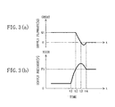
- the actual flowrate Q of supply of operating oil substantially corresponds to the flowrate command value Qi and the oil hydraulic cylinder is actuated at a constant speed ( Figure 3 ).
- the position sensor (11) detects the spool position of the electromagnetic proportional valve (6) . Since feedback control is performed based on the result of the spool position detection, this makes it possible to control not only the electromagnetic proportional valve (6) but also the rate of flow of operating oil with an extremely high degree of accuracy. That is to say, the non-linearity, hysteresis, variation, et cetera of the suction characteristics of the solenoid (6b) with respect to the value of an electric current applied are completely corrected by the feedback control on the basis of signals from the position sensor (11) and, as indicated by a solid line of Figure 4(a), there is achieved considerable improvement in static characteristic in the flowrate control. Furthermore, since the present embodiment employs a feedback control method, this makes it possible to provide a marked increase in the operating speed of the spool (6a) in comparison with a case employing an open control method. There is achieved improvement in flowrate control response.
- the oil hydraulic cylinder of the main machine reaches a stroke end and makes approximately no further movement (time tl of Figure 3 ).
- the pressure P of the downstream supply passageway (5b) in the PQS valve (2) increases.
- the pressure P is detected by the pressure sensor (10) and is fed back to the controller (12) .
- the PQ selecting part (12c) of the controller (12) selects an arithmetic value calculated by the pressure deviation arithmetic part (12a) , i.e., a pressure deviation.
- the valve travel of the electromagnetic proportional valve (6) is feedback controlled based on that pressure deviation so that the pressure P of supply of operating oil to the main machine side agrees with the pressure command value Pi (PRESSURE CONTROL MODE).
- the flowrate Q of supply of operating oil to the main machine side will not become zero immediately.
- the spool (6a) of the electromagnetic proportional valve (6) assuming the supply position is shifted gradually, thereby reducing the pass cross-sectional area of the operating oil.
- the supply flowrate Q of operating oil gradually decreases (from t2 to t3 ), as shown in the Figure.
- the position of the electromagnetic proportional valve (6) changes to the stop position, and the supply flowrate Q becomes zero ( t3 ).
- the pressure of the oil hydraulic cylinder ( ⁇ P ) increases to a maximum the instant the supply flowrate Q becomes zero.
- the spool (6a) of the electromagnetic proportional valve (6) is further shifted, changing its position to the discharge position.
- the pressure P decreases down to the pressure command value Pi and becomes steady there ( t4 ).
- the operation of starting a supply of operating oil to the main machine side from the electromagnetic proportional valve (6) and the operation of stopping a supply of operating oil to the main machine side from the electromagnetic proportional valve (6) are repeatedly carried out depending on the leakage of operating oil from the main oil hydraulic circuit.
- the electromagnetic proportional valve (6) for adjusting the flowrate of supply of operating oil to the main oil hydraulic circuit (1) assumes an additional position, i.e., the discharge position, for allowing operating oil to be discharged from the main machine side.
- the pressure sensor (10) for detecting the pressure P of the supply passageway (5a) arranged downstream of the electromagnetic proportional valve (6) and the position sensor (11) for detecting the position of the spool (6a) of the electromagnetic proportional valve (6) are provided.
- the electromagnetic proportional valve (6) is provided with the discharge position and the valve travel of the electromagnetic proportional valve (6) is subjected to feedback control based on a signal from the pressure sensor (10) .
- the pressure sensor (10) As a result of such arrangement, it becomes possible to control the supply pressure to zero pressure by eliminating the minimum controllable pressure Pmin of the pressure P of supply of operating oil to the main machine side. As a result of this, it becomes possible to satisfactorily cope with requirements for example in a low pressure clamping process in an injection molding machine.
- the configuration of the PQS valve (2) requires additional components, i.e., the pressure sensor (10) and the position sensor (11) , in comparison with a conventional flowrate regulating valve device with a proportional electromagnetic relief valve (see Figure 6 ).
- the PQS valve (2) requires neither a pressure proportional valve (8) nor its electric current driver circuit (9) which is conventionally required. This offsets the increase in costs due to the employment of the sensors (10,11) .
- FIG. 5 there is shown an arrangement of a PQS valve (20) (a hydraulic circuit system) according to a second embodiment of the present invention.
- the construction of the PQS valve (20) of the second embodiment resembles that of the PQS valve (2) of the first embodiment, with the exception of the difference in the orifice configuration of the downstream pilot passageway (15) .
- Components of the PQS valve (20) which are similar to those in the PQS valve (2) have been given the same reference numbers and their description will be omitted.
- the orifice (17) of the downstream pilot passageway (15) serves as a differential pressure creating source when functioning as a pilot relief valve together with the safety valve (18) and the differential pressure compensation valve (7) .
- the orifice (17) works to apply adequate damping to the operation of the valve element (7a) of the differential pressure compensation valve (7) , for stabilizing the operation of the valve element (7a) .
- the operation of the valve element (7a) becomes slow at the time of the closing operation of the differential pressure compensation valve (7) . This contributes to the fact that the flowrate start-up response to the main machine side is not very fast, even when the operating speed of the spool (6a) of the electromagnetic proportional valve (6) is increased, as described above.
- the downstream pilot passageway (15) is provided with a first orifice (21) of a greater operating oil pass cross-sectional than that of the orifice (17) of the first embodiment and a second orifice (22) of a greater degree of restriction than that of the first orifice (21) (in other words, the second orifice (22) has an operating oil pass cross-sectional area smaller than that of the first orifice (21) ).
- the first and second orifices are disposed in series.
- a bypass passageway (23) bypassing the second orifice (22) is provided with a check valve (24) which accepts a flow of operating oil flowing toward the differential pressure compensation valve (7) but prevents reversal of that operating oil flow.
- the first orifice (21) has a circular cross-section having a diameter of for example about 2 mm.
- the second orifice (22) has a circular cross-section having a diameter of for example about 1 mm.
- valve element (7a) of the differential pressure compensation valve (7) when the valve element (7a) of the differential pressure compensation valve (7) is placed in the open state, operating oil passing through the downstream pilot passageway (15) is given relatively great resistance by the first and second orifices (21) , (22) . Therefore, as in the first embodiment, adequate damping is applied to the operation of the valve element (7a) .
- the valve travel of the electromagnetic proportional valve (6) is controlled by the controller (12) so that it becomes decreased.
- the upstream hydraulic pressure of the electromagnetic proportional valve (6) rapidly increases.
- Such a high upstream pressure acts on the valve element (7a) of the differential pressure compensation valve (7) through the branch passageway (14) .
- operating oil flows through the downstream pilot passageway (15) from the differential pressure compensation valve (7) toward the downstream supply passageway (5b) , and this operating oil flow is given pass resistance by both the first and second orifices (21), (22) .
- valve element (7a) since, as described above, relatively high upstream pilot pressure is acting on the valve element (7a) , this allows the valve element (7a) to perform its opening operation at high speed. After all, the response delay will not become a problem at the time when the supply flowrate decreases.
- the formation of thin molding products becomes easier than conventional.
- cost reduction is achieved by shortening the cycle of molding.
- resin injected may grow cold and harden before being distributed completely into the inside of a metal mold.
- fast flowrate start-up response is particularly required.
- the PQS valve of the present embodiment capable of providing improvement in response is especially effective.
- the present invention is not limited to the first and second embodiments.
- the present invention includes other various arrangements.
- the hydraulic circuit system of the present invention employs a single PQS valve, i.e., the PQS valve (2, 20) .
- the hydraulic circuit system of the present invention is not necessarily constructed as an integral-type composite valve.
- the main machine is not limited to injection molding machines.
- the present invention is applicable to various machine apparatus provided with a hydraulic actuator such as a hydraulic cylinder, a hydraulic motor, et cetera.
- controller is not limited to the digital controller (12) employed in each of the foregoing embodiments.
- an analog controller having the same functions as the digital controller (12) may be constructed using a comparator, an operational amplifier, et cetera.
- the electromagnetic proportional valve of the present invention is not limited to the valve described in the foregoing embodiments. Any type of throttle valve with ports A, P, and T may be used as long as it is able to electrically vary the amount of restriction.
- the electromagnetic proportional valve of the present invention may be either a direct acting type for directly pressing the spool (6a) with the solenoid (6b) or a pilot type for indirectly actuating the spool (6a) by the use of a small-size pilot valve.
- a pilot type electromagnetic proportional valve either a type employing a proportional valve as a pilot valve and a type employing a servo valve (e.g., a nozzle flapper) as a pilot valve may be used. Since the present invention is provided with a spool position sensor, the electromagnetic proportional valve (6) may be replaced with a servo valve.
- the present invention provides a hydraulic circuit system capable of speeding up the operation of an actuator of a main machine and of extending the region of controllable pressure to substantially a zero point. Therefore, the hydraulic circuit system of the present invention exhibits extremely excellent characteristics when employed as a device for driving a hydraulic actuator of a machine apparatus. Particularly when applied to an injection molding machine, the present invention achieves considerable improvement in the quality of molding products and shortens the cycle time. Besides, the present invention satisfactorily meets requirements in a low pressure clamping process that cannot be dealt effectively with by conventional techniques. The industrial applicability of the present invention is high.
Landscapes
- Engineering & Computer Science (AREA)
- Mechanical Engineering (AREA)
- General Engineering & Computer Science (AREA)
- Physics & Mathematics (AREA)
- Fluid Mechanics (AREA)
- Chemical & Material Sciences (AREA)
- Analytical Chemistry (AREA)
- Fluid-Pressure Circuits (AREA)
- Moulds For Moulding Plastics Or The Like (AREA)
- Injection Moulding Of Plastics Or The Like (AREA)
- Magnetically Actuated Valves (AREA)
Abstract
Description
- The present invention relates in general to a hydraulic circuit system for driving a hydraulic actuator of a mechanical apparatus. The present invention pertains in particular to the technical field of controlling the flowrate and the pressure of operating fluid in order to provide correct control of the operating speed and the working force of such a hydraulic actuator.
- As a hydraulic circuit system of the type described above, an oil hydraulic circuit system housing therein a flowrate electromagnetic proportional valve (hereinafter a flowrate proportional valve) for controlling the flowrate of supply of operating oil to an actuator and a pressure electromagnetic proportional valve (hereinafter a pressure proportional valve) for controlling the pressure of supply of operating oil to the actuator has been known widely in the art. In such an oil hydraulic circuit system, each proportional valve is controlled by a dedicated driver circuit.
- In such an oil hydraulic circuit system, a flowrate proportional valve (6) is interposingly disposed in a supply passageway (5) through which operating oil is supplied to an oil hydraulic actuator of an oil hydraulic circuit (1) of a main machine (a mechanical apparatus), as shown in Figure 6. The actuator is connected to a port A of the downstream side of the flowrate proportional valve (6). Connected to a port P of the upstream side of the flowrate proportional valve (6) is for example a fixed displacement pump (3). In addition, a differential pressure compensation valve (7) is disposed. The differential pressure compensation valve (7) receives a pilot pressure from the upstream side of the flowrate proportional valve (6) and another pilot pressure from the downstream side of the flowrate proportional valve (6) and bypasses operating oil to a port T from an upstream supply passageway (5a) so that the difference in pressure between these pilot pressures is held substantially constant.
- Further, a downstream pilot passageway (15), for guiding a pilot pressure to the differential pressure compensation valve (7) from downstream of the flowrate proportional valve (6), is provided with an orifice (17). A pressure proportional valve (8), for adjusting the downstream pressure by relieving operating oil therefrom, is connected to the pilot passageway (15) between the orifice (17) and the differential pressure compensation valve (7). The valve travel of the flowrate proportional valve (6) and the valve travel of the pressure proportional valve (8) are controlled by electric current drivers (9, 9), respectively.
- Such a conventional oil hydraulic circuit system automatically switches between a flowrate control mode of operation and a pressure control mode of operation according to the operating state of the actuator. A case in which operating oil is supplied to a main oil hydraulic cylinder will be described. With the difference in pressure between the upstream and downstream sides of the flowrate proportional valve (6) held substantially constant, the amount of supply of operating oil to the oil hydraulic cylinder is adjusted by controlling the valve travel of the flowrate operational valve (6), to control the operating speed of the oil hydraulic cylinder (FLOWRATE CONTROL MODE). During this mode, operating oil discharged from the pump (3) is delivered to the oil hydraulic cylinder by way of the port P, the flowrate proportional valve (6), and the port A, while at the same time surplus operating oil is bypassed, through the port T, to an oil tank (4) from the differential pressure compensation valve (7).
- When the cylinder reaches its stroke end, the hydraulic pressure of the downstream supply passageway (5b) sharply increases. When this hydraulic pressure exceeds the set pressure of the pressure proportional valve (8), the pressure proportional valve (8), the differential pressure compensation valve (7), and the orifice (17) together function as a so-called pilot-type electromagnetic proportional relief valve, thereby preventing further pressure increase. The pilot pressure of the downstream pilot passageway (15) can be changed by relief pressure control by the pressure proportional valve (8). As a result of this, not only the discharge pressure of the pump (3) but also the pressure of supply of operating oil to the oil hydraulic cylinder can be controlled by making a change in the relief pressure of the differential pressure compensation valve (7) (PRESSURE CONTROL MODE).
- However, for the case of the above-described conventional oil hydraulic circuit system, both the supply flowrate and the supply pressure of operating oil to be supplied to the actuator directly reflect the characteristics of solenoids of the electromagnetic valves (6, 8). Therefore, variations in the operating oil supply flowrate and pressure with respect to the value of output electric currents from the electric current drivers (9, 9) of the electromagnetic valves (6, 8) are non-linear and hysteretic (see a broken-line graph of Figure 4), therefore making it difficult to perform operatiang oil flowrate and pressure control with a high degree of accuracy. Further, owing to such an open control method employing no electric sensor, it is impossible to increase the speed of response with respect to the variation in command value, to a greater extent.
- Furthermore, as to the controlling of the supply pressure of operating oil, there are problems about the limit of lower-pressure side control. In other words, in the above-described conventional oil hydraulic circuit system, even when the value of electric current to the pressure proportion valve (8) is reduced to zero, the relief pressure of the differential pressure compensation valve (7) will drop only to a given pressure level corresponding to the energizing force of the spring member. It is therefore impossible to reduce the pressure of supply of operating oil to the actuator below the given pressure level. In other words, the above-described conventional construction employs a relieve valve for pressure control, which means that there exists a controllable oil pressure lower limit (hereinafter also referred to a minimum controllable pressure). Therefore, it is impossible to perform pressure control in regions below such a lower limit. With respect to this point, for the case of, for example, injection molding machines, there is a low pressure clamping process for metal mold protection. In this step, pressure control at a level lower than conventional minimum control pressure levels is required. That is to say, improvements also in pressure control in conventional hydraulic circuit systems have been strongly desired.
- Bearing in mind the above-described problems with the prior art techniques, the present invention was made. Accordingly, an object of the present invention is to achieve improvements in the control accuracy and the response of a hydraulic circuit system (2, 20) provided with an electromagnetic proportional valve (6) in a supply passageway (5) through which operating oil (operating fluid) is supplied to a hydraulic actuator, for controlling the supply flowrate and the supply pressure of the operating fluid, and particularly for extending the region of controllable pressure to substantially a zero point by eliminating a minimum controllable limit with respect to the supply hydraulic pressure. Another object of the present invention is to provide a valve structure capable of placing a restraint on the increase in costs.
- The present invention provides the following means as solutions to the above-described problems.
- A first invention is directed to a hydraulic circuit system (2, 20) comprising an electromagnetic proportional valve (6), disposed interposingly in a supply passageway (5) through which operating fluid is supplied to a hydraulic actuator, for adjusting the supply flowrate of operating fluid and a differential pressure compensation valve (7) for receiving a pilot pressure from the upstream side of the electromagnetic proportional valve (6) and a pilot pressure from the downstream side of the electromagnetic proportional valve (6) and for bypassing operating fluid to a tank (4) from a supply passageway (5a) on the upstream side of the electromagnetic proportional valve (6) so that the difference between the pilot pressures is held constant.
- In the hydraulic circuit system (2, 20) of the first invention, the electromagnetic proportional valve (6) assumes, in addition to a supply position for allowing operating fluid to be supplied to the hydraulic actuator, at least a discharge position for allowing operating fluid to be discharged out of the hydraulic actuator. The hydraulic circuit system (2, 20) further comprises; a pressure sensor (10) for detecting the working hydraulic pressure of a supply passageway (5b) on the downstream side of the electromagnetic proportional valve (6) and for outputting an electric signal; a position sensor (11) for detecting the spool position of the electromagnetic proportional valve (6) and for outputting an electric signal; and a controller (12) for receiving an electric signal from the pressure sensor (10) and an electric signal from the position sensor (11) and for feedback controlling the valve travel (the spool position) of the electromagnetic proportional valve (6) so that the supply flowrate and/or the supply hydraulic pressure of operating fluid to be supplied to the hydraulic actuator becomes a control command value.
- In accordance with the first invention, during the operation of the actuator the spool position of the electromagnetic proportional valve (6) is controlled by the controller (12), with the difference in pressure between the upstream and downstream sides of the electromagnetic proportional valve (6) held constant by the function of the differential pressure compensation valve (7). As a result of this, the supply flowrate of operating fluid to be supplied to the actuator is controlled (FLOWRATE CONTROL MODE). During this period, the position sensor (11) detects the actual spool position of the electromagnetic proportional valve (6). Feedback control is performed based on the result of such position detection. Therefore, the rate of flow of operating fluid is controlled with an extremely high degree of accuracy and response. Since solenoid non-linearity characteristics are absorbed apparently by the feedback control, this makes it possible to not only linearize the flowrate control characteristics of the operating fluid but also eliminate hysteresis.
- On the other hand, when the actuator reaches its stroke end and enters the state in which it hardly makes further movement, the hydraulic pressure of the downstream supply passageway (5b) increases with the increase in load. This increase is detected by the pressure sensor (10). The controller (12) performs, based on the detection value, feedback control of the electromagnetic proportional valve (6) (PRESSURE CONTROL MODE). In other words, when the electromagnetic proportional valve (6) is assuming the supply position, the supply flowrate of operating fluid is adjusted by controlling, based on the deviation between a value detected by the pressure sensor (10) and the pressure command value, the valve travel (the spool position) of the electromagnetic proportional valve (6). On the other hand, when the electromagnetic proportional valve (6) is assuming the discharge position, the discharge amount of operating fluid from the downstream supply passageway (5b) is adjusted by controlling the spool position of the electromagnetic proportional valve (6). In this way, the hydraulic pressure of the downstream supply passageway (5b) is maintained at the pressure command value in the end. Also in this pressure control mode, it is possible to provide improvement in control accuracy, response, solenoid non-linearity characteristics, et cetera by feedback control, as in the flowrate control mode. Further, the supply hydraulic pressure of operating fluid to be supplied to the actuator can be reduced to zero by changing the position of the electromagnetic proportional valve (6) to the discharge position for the operating fluid to be discharged out of the actuator.
- The first invention requires the pressure sensor (10) and the position sensor (11) which are components that conventional structures do not require. However, the first invention requires neither a pressure proportional valve (8) nor an electric current driver circuit for the pressure proportional valve (8). This offsets the increase in costs due to the employment of the electric sensors.
- In a second invention, the controller (12) of the hydraulic circuit system (2, 20) comprises: a flowrate deviation arithmetic part (12b) for finding, based on an electric signal from the position sensor (11), an actual supply flowrate of operating fluid being supplied to the hydraulic actuator and for performing an arithmetical operation to calculate a flowrate deviation by subtracting the found actual supply flowrate from a flowrate command value; a pressure deviation arithmetic part (12a) for finding, based on an electric signal from the pressure sensor (10), an actual supply hydraulic pressure of operating fluid being supplied to the hydraulic actuator and for performing an arithmetic operation to calculate a pressure deviation by subtracting the found actual supply hydraulic pressure from a pressure command value; a PQ selecting part (12c) for selecting the smaller of the flowrate deviation and the pressure deviation and for performing, based on the selected deviation, an arithmetic operation to calculate a desired spool position for the electromagnetic proportional valve (6); and an electric current driver (12d) for applying an electric current to a solenoid (6b) of a spool (6a) of the electromagnetic proportional valve (6) so that the spool (6a) assumes the desired spool position found by the PQ selecting part (12c).
- In accordance with the second invention, the flowrate deviation arithmetic part (12b) performs an arithmetic operation to calculate the flow deviation between an actual supply flowrate of operating fluid and a flowrate command value. On the other hand, the pressure deviation arithmetic part (12a) performs an arithmetic operation to calculate the pressure deviation between an actual supply pressure of operating fluid and a pressure command value. When an actual supply flowrate and/or an actual supply pressure exceeds the control command value, the PQ selecting part (12c) selects the flowrate or the pressure, whichever exceeds the control command value to a further extent than the other. On the other hand, when neither an actual supply flowrate nor an actual supply pressure is more than the control command value, the PQ selecting part (12c) selects the flowrate or the pressure, whichever is more approximate to the control command value than the other. In other words, the PQ selecting part (12c) deems the state, in which the flowrate and/or the pressure exceeds the command value, dangerous. Then, the PQ selecting part (12c) determines degrees of danger from the flowrate deviation and from the pressure deviation respectively and selects the flowrate deviation or the pressure deviation, whichever is greater in degree of danger. In this way, the working and effects of the first invention are realized.
- In a third invention, the differential pressure compensation valve (7) of the hydraulic circuit system (2, 20) is provided with a spring member (7b) for energizing a valve element (7a) of the differential pressure compensation valve (7) in the valve-closing direction and receives a pilot pressure which causes the valve element (7a) to move in the valve-closing direction and another pilot pressure which causes the valve element (7a) to move in the valve-opening direction, from the downstream side of the electromagnetic proportional valve (6) and from the upstream side of the electromagnetic proportional valve (6), respectively. A pilot passageway (15) on the downstream side of the electromagnetic proportional valve (6) for guiding a pilot pressure to the differential pressure compensation valve (7) from the downstream side of the electromagnetic proportional valve (6) is provided with an orifice (17) capable of restricting a flow of operating fluid and a pilot relief valve (18) is connected to the pilot passageway (15) between the orifice (17) and the differential pressure compensation valve (7).
- In accordance with the third invention, even if the spool (6a) of the electromagnetic proportional valve (6) is stuck in the supply position due to an electrical malfunction of the controller (12) and foreign particles contained in the operating fluid, the pilot relief valve (18), the differential pressure compensation valve (7), and the orifice (17) together function as a so-called pilot type relief valve when the hydraulic pressure of the downstream supply passageway (5b) exceeds the set pressure of the pilot relief valve (18), thereby preventing the increase in hydraulic pressure in the downstream supply passageway (5b). In addition, during the closing/opening operation of the valve element (7a) of the differential pressure compensation valve (7), a flow of operating fluid in the downstream pilot passageway (15) receives a pass resistance from the orifice (17), by which adequate damping is applied to the operation of the valve element (7a) for the purpose of stabilization.
- By the way, if the orifice (17) is provided in the pilot passageway (15) in order to restrict a flow of operating fluid, this results in decreasing the operating speed of the valve element (7a) of the differential pressure compensation valve (7). Therefore, there is a worry that the response drops when increasing the flowrate of supply of operating fluid to the actuator. In other words, if the valve travel of the electromagnetic proportional valve (6) is greatened in order to increase the supply flowrate of operating fluid to be supplied to the actuator, this temporarily decreases the difference in pressure between the upstream and downstream sides of the electromagnetic proportional valve (6), thereby closing the valve element (7a) of the differential pressure compensation valve (7). More specifically, the operating fluid flows in the direction of the differential pressure compensation valve (7) in the downstream pilot passageway (15) and, as a result, the valve element (7a) of the differential pressure compensation valve (7) is shifted in the valve-closing direction. However, originally the degree of force trying to place the valve element (7a) in the closed position is just as great as the energizing force of the spring member (7b) and, besides, the operating fluid flow is restricted by the orifice (17), as described above. As a result of this, the closing operation of the valve element (7a) of the differential pressure compensation valve (7) is delayed. This results in a response delay when increasing the flowrate of supply of operating fluid to the electromagnetic proportional valve (6).
- In consideration of such a transitional delay, in a fourth invention the hydraulic circuit system (20) of the third invention preferably employs an arrangement in which a first orifice (21) and a second orifice (22) of a greater degree of restriction than that of the first orifice (21) are provided in series in the downstream pilot passageway (15) and a bypass passageway (23) bypassing the second orifice (22) is provided with a check valve (24) which accepts a flow of operating fluid moving toward the differential pressure compensation valve (7) but prevents reversal of the operating fluid flow.
- As a result of such arrangement, for example when the valve travel of the electromagnetic proportional valve (6) is greatened in order to increase the flowrate of supply of operating fluid to the actuator, the operating fluid will flow toward the differential pressure compensation valve (7) in the downstream pilot passageway (15). Although this operating fluid flow passes through the first orifice (21) of a smaller degree of restriction, it bypasses the second orifice (22) of a greater degree of restrictions. Therefore, it becomes possible to quickly place the valve element (7a) of the differential pressure compensation valve (7) in the closed state by making the pass resistance relatively small. This makes it possible to quickly increase the flowrate of supply of operating fluid to the actuator.
- On the other hand, when decreasing the flowrate of supply of operating fluid to the actuator, the valve travel of the electromagnetic proportional valve (6) is reduced. At this time, the hydraulic pressure of the upstream side of the electromagnetic proportional valve (6) will rapidly increase, and an extremely high hydraulic pressure acts on the valve element (7a) of the differential pressure compensation valve (7), thereby placing the valve element (7a) in the opening state. During this period, operating fluid flows toward the downstream supply passageway (5b) from the differential pressure compensation valve (7) in the downstream pilot passageway (15). This operating fluid flow is given pass resistance by the first and second orifices (21) and (22). However, as described above, since the valve element (7a) of the differential pressure compensation valve (7) is in receipt of an extremely high upstream pilot pressure, the valve element (7a) of the differential pressure compensation valve (7) is sufficiently quickly placed in the open state in spite of the fact that the operating fluid flow is restricted in the downstream pilot passageway (15). After all, at the time of reducing the supply flowrate of operating fluid, response delay will not be a problem; rather, the stable operation of the differential pressure compensation valve (7) is maintained because the operating fluid flow in the downstream pilot passageway (15) is sufficiently restricted by the second orifice (22).
- To sum up, in accordance with the fourth invention, the provision of the orifices (21, 22) in the downstream pilot passageway (15) makes it possible to secure stability by restricting the opening operation of the valve element (7a) of the differential pressure compensation valve (7) to such an extent that its response is not spoiled. On the other hand, response can be secured by not restricting the closing operation of the valve element (7a). Therefore, both the stability and the response of the flowrate of supply of operating fluid to the actuator can be achieved at high level.
- In a fifth invention, the hydraulic actuator is employed to actuate an injection molding machine.
- In other words, for the case of actuators of injection molding machines, they are in general required to provide high reproducibility while at the same time coping with wide molding conditions depending on the difference in molding product shape and material. The hydraulic circuit system (2, 20) of the first invention achieves improvement in the operating speed and the working force of the actuator, which is extremely effective to the above requirement. The first invention makes it possible to considerably improve the quality of molding products.
- Further, in accordance with the first invention, it is possible to perform control, with the pressure of supply of operating fluid to the actuator reduced to zero. Therefore, it is possible to satisfactory cope with requirements in a low pressure clamping process in an injection molding machine. Furthermore, if the supply flowrate of operating fluid is increased with a high degree of response, this not only facilitates the formation of thin molding products by an injection molding machine but also shortens the cycle of molding. In this light, the working and effects of the invention are extremely effective when applied to an injection molding machine.
- In accordance with the present invention, in the hydraulic circuit system (2, 20) the electromagnetic proportional valve (6) is provided interposingly in the supply passageway (5) through which operating fluid is supplied to the hydraulic actuator. The differential pressure compensation valve (7), for receiving a pilot pressure from the upstream side of the electromagnetic proportional valve (6) and a pilot pressure from the downstream side of the electromagnetic proportional valve (6) and for bypassing operating fluid from the upstream supply passageway (5a) so that the difference between these two pilot pressures is held constant, is provided. In such a case, the electromagnetic proportional valve (6) further assumes the discharge position for allowing operating fluid to be discharged from the actuator. The electromagnetic proportional valve (6) is further provided with the pressure sensor (10) capable of detecting the working hydraulic pressure of the supply passageway (5b) on the downstream side of the electromagnetic proportional valve (6) and the position sensor (11) capable of detecting the spool position of the electromagnetic proportional valve (6). Since the spool position (valve travel) of the electromagnetic proportional valve (6) is feedback controlled based on output signals from these sensors, this makes it possible to control the supply flowrate and the supply pressure of operating fluid with an extremely high degree of accuracy.
- Further, by virtue of such feedback control, it is possible to apparently eliminate solenoid non-linearity characteristics, thereby making it possible to linearize the control characteristics of the supply flowrate and the supply pressure of operating fluid. Furthermore, it is possible to increase the closing/opening speed of the electromagnetic proportional valve (6) to a further extent than conventional, thereby achieving improvements in flowrate response. Further, by changing the position of the electromagnetic proportional valve (6) to the discharge position, it becomes possible to discharge operating fluid out of the actuator. Therefore, it is possible to eliminate uncontrollable regions by reducing the control pressure to zero.
- Besides, the present invention eliminates the need for the provision of a pressure proportional valve (8) and its electric current driver circuit which have been required in conventional prior art techniques. This offsets costs increased by the addition of the sensors.
- In accordance with the second invention, the electromagnetic proportional valve (6) is feedback controlled according to the actual supply state of operating fluid by the flowrate deviation arithmetic part (12b), the pressure deviation arithmetic part (12a), the PQ selecting part (12c), et cetera, thereby making it possible to satisfactorily obtain the effects of the first invention.
- In accordance with the third invention, the downstream pilot passageway (15), for guiding a pilot pressure to the differential pressure compensation valve (7) of the hydraulic circuit system (2, 20) from the downstream side of the electromagnetic proportional valve (6), is provided with the orifice (17) capable of restricting a flow of operating fluid and the pilot relief valve (18). This makes it possible to obtain sufficient safety even when the controller (12) or the electromagnetic proportional valve (6) malfunctions. Besides, by applying adequate damping to the valve element (7a) of the differential pressure compensation valve (7), its operation can be stabilized.
- In accordance with the fourth invention, instead of the orifice of the third invention, the first orifice (21) and the second orifice (22) having different degrees of restriction are provided in series. The passageway (23) bypassing the second orifice (22) of a greater degree of restriction is provided with the check valve (24). As a result of this, the operation of the differential pressure compensation valve (7) is stabilized and the closing operation speed of the valve element (7a) of the differential pressure compensation valve (7) is increased, thereby making it possible to further improve, when increasing the flowrate of supply of operating fluid to the actuator, its flowrate response.
- In accordance with the fifth invention, the hydraulic circuit system (2, 20) is applied to an injection molding machine. This can provide improvement in productivity by shortening the time of cycle. Improvement in the controllability of the operatiang speed and the working force considerably improves the quality of molding products, and the molding of thin molding products is facilitated. Further, it becomes possible to satisfactorily cope with requirements in a low pressure clamping process and cost reduction can be achieved.
-
- Figure 1 is a diagram showing an arrangement of a PQS valve according to a first embodiment of the present invention;
- Figure 2 is a diagram corresponding to Figure 1 when the electromagnetic proportional valve is in a supply position;
- Figure 3 is comprised of Figures 3(a) and 3(b) which are time chart diagrams respectively showing a variation in the supply flowrate of operating oil and a variation in the supply pressure of operating oil, when a mold clamping cylinder of an injection molding machine is actuated;
- Figure 4 is comprised of Figures 4(a) and 4(b) which are characteristic diagrams respectively showing, in comparative manner with prior art techniques, a correlation between the control signal (electric current value) fed to the electromagnetic proportional valve and the flowrate of supply of operating oil and a correlation between the control signal and the pressure of supply of operating oil;
- Figure 5 is a diagram corresponding to Figure 1 according to a second embodiment of the present invention; and
- Figure 6 is a diagram corresponding to Figure 1 showing an example of a conventional hydraulic circuit system.
- Hereinafter, preferred embodiments of the present invention will be described in detail with reference to the drawings. A hydraulic circuit system of the present invention is applied to a servo valve device which drives an oil hydraulic cylinder of an injection molding machine et cetera.
- Referring first to Figure 1, there is shown a pressure/flowrate servo valve device (2)(hereinafter a PQS valve). The PQS valve (2), connected to a main oil hydraulic circuit (1) of a main machine such as an injection molding machine, provides a supply of operating oil (operating fluid) to an actuator such an oil hydraulic cylinder and controls the operating speed and the working force of the actuator by adjusting the supply flowrate (Q) and the supply pressure (P) of the operating oil. The PQS valve (2) is provided with a port A connected to the main oil hydraulic circuit (1), a port P connected to a fixed displacement type pump (3), and ports T and Y each connected to an oil tank (4). An electromagnetic proportional valve (6) for supply flowrate control is disposed interposingly in an operating oil supply passageway (5) between the port P and the port A. The PQS valve (2) is further provided with a differential pressure compensation valve (7). The differential pressure compensation valve (7) receives a pilot pressure from a supply passageway (5a) located upstream of the electromagnetic proportional valve (6) and another pilot pressure from a supply passageway (5b) located downstream of the electromagnetic proportional valve (6) and bypasses operating oil to the oil tank (4) from the upstream supply passageway (5a) so that the difference between the pilot pressures is held substantially constant.
- The PQS valve (2) further includes a pressure sensor (10) for detecting the working oil pressure (P) of the supply passageway (5b) located downstream of the electromagnetic proportional valve (6) and outputs an electrical signal and a position sensor (11) for detecting the position of a spool (6a) of the electromagnetic proportional valve (6) and outputs an electrical signal. Further, the PQS valve (2) is provided with a controller (12). Upon receipt of output signals from the sensors (10) and (11), the controller (12) feedback controls the position of the spool (6a) of the electromagnetic proportional valve (6), i.e., the valve travel of the electromagnetic proportional valve (6), so that the supply flowrate Q and the supply pressure P of the operating oil which is supplied to the main oil hydraulic circuit (1) become a command value Qi and a command value Pi, respectively.
- More specifically, the electromagnetic proportional valve (6) has a solenoid (6b) which is actuated by a control signal (electric current) from the controller (12). The position of the spool (6a) is controlled in resistance to press energizing force by a spring (6c). The electromagnetic proportional valve (6) assumes, in a switching manner, the following positions, namely a supply position for allowing operating oil to be supplied to the main machine, a discharge position for allowing operating oil to be discharged out of the main machine side, and a stop position for stopping the supply and discharge of operating oil. When the electromagnetic proportional valve (6) assumes either the supply or the discharge position, it is arranged such that the pass cross-sectional area of the operating oil in the electromagnetic proportional valve (6) is controlled continuously. As shown in the Figure, the spool (6a) is press energized by the spring (6c) toward the right-hand side of the Figure, in other words the spool (6a) is shifted toward the discharge position. When the spool (6a) is switched to the discharge position, the electromagnetic proportional valve (6) shuts off the upstream supply passageway (5a) and brings the downstream supply passageway (5b) into communication with a discharge passageway (13), so that the operating oil of the main machine side is returned to the oil tank (4). During this period, the pass cross-sectional area of the returning operating oil is continuously controlled by continuously varying the position of the spool (6a).
- Furthermore, when the spool (6a) is shifted, by the operation of the solenoid (6b), to the supply position (i.e., when the spool (6a) is shifted to the left-hand side in the Figure) in resistance to an energizing force provided by the spring (6c) (see Figure 2), the electromagnetic proportional valve (6) shuts off the discharge passageway (13) while at the same time bringing the upstream and downstream supply passageways (5a, 5b) of the supply passageway (5) into communication with each other so that operating oil discharged from the pump (3) is delivered to the main machine side. During this period, the position of the spool (6a) is continuously varied, thereby causing the pass cross-sectional area of the operating oil to continuously vary, and the flowrate Q of supply of operating oil to the main machine side from the pump (3) will be controlled continuously. Further, when the spool (6a) assumes an intermediate position between the supply position and the discharge position (i.e., the stop position), the electromagnetic proportional valve (6) shuts off the upstream and downstream supply passageways (5a, 5b) of the supply passageway (5) and the discharge passageway (13).
- The position sensor (11) is attached to the electromagnetic proportional valve (6). When the spool (6a) of the electromagnetic proportional valve (6) assumes the stop position (i.e., the central position), the position sensor (11) provides an output of zero value. When the spool (6a) assumes the supply position (i.e., the right-hand position in the Figure), the sensor output of positive value increases as the pass cross-sectional area of the operating oil increases by variation in the position of the spool (6a). On the other hand, when the spool (6a) assumes the discharge position (i.e., the left-hand position in the Figure), the sensor output of negative value decreases as the pass cross-sectional area of the operating oil increases by variation in the position of the spool (6a).
- The differential pressure compensation valve (7) is a relief valve in which a valve element (7a) such as a poppet is energized in the valve-closing direction by a spring (7b) (a spring member). The differential pressure compensation valve (7) is disposed in a branch passageway (14) branching off from the upstream supply passageway (5a), thereby causing the branch passageway (14) to bypass the discharge passageway (13). To sum up, the downstream pilot passageway (15) branching off from the downstream supply passageway (5b) is connected to the same side that the spring (7b) is mounted. A downstream pilot pressure is applied, in the valve-closing direction, to the valve element (7a). On the other hand, the hydraulic pressure of the upstream supply passageway (5a) (upstream pilot pressure) is applied, in the valve-opening direction, to the valve element (7a) through the branch passageway (14).
- The differential pressure compensation valve (7) is placed in the open state when a press force applied to the valve element (7a) by the upstream pilot pressure becomes greater than an energizing force provided by the spring (7b), in comparison with a press force applied to the valve element (7a) by the downstream pilot pressure, thereby allowing the operating oil in the upstream supply passageway (5a) to be bypassed, through the branch passageway (14), to the discharge passageway (13). When there is a drop in the upstream pilot pressure, the valve element (7a) is placed in the closed state to interrupt the bypassing of operating oil. As a result, the upstream pilot pressure increases again. The difference in pressure between the upstream and downstream sides of the electromagnetic proportional valve (6) is kept substantially constant by repetition of such closing/opening movement of the valve element (7a). The difference in pressure between the upstream and downstream sides of the electromagnetic proportional valve (6) is so compensated in the above-described way as to be kept substantially constant, which provides a constant correlation between the valve travel of the electromagnetic proportional valve (6) by which the upstream supply passageway (5a) and the downstream supply passageway (5b) are communicated together (i.e., the position of the spool (6a) corresponding to the pass cross-sectional area of the operating oil) and the actual supply flowrate of operating oil. This makes it possible to find an actual supply flowrate on the basis of the spool position.
- The downstream pilot passageway (15) is provided with an orifice (17) capable of restricting a flow of operating oil, and a branch passageway (15a) is connected between the orifice (17) and the differential pressure compensation valve (7). The branch passageway (15a) is provided with a safety valve (18a) (a pilot relief valve). The safety valve (18) is placed in the open state when the hydraulic pressure of the branch passageway (15a) exceeds the set pressure of the spring, so that the hydraulic pressure of the downstream pilot passageway (15) is relieved through the branch passageway (15a). This results in the difference in pressure between the sides of the orifice (17). The hydraulic pressure of the downstream pilot passageway (15) drops, thereby placing the differential pressure compensation valve (7) in the open state. When the differential pressure compensation valve (7) assumes the open state, the operating oil in the supply passageway (5) is discharged to the oil tank (4) through the port T. In other words, the differential pressure compensation valve (7) has a function of serving as a pilot relief valve capable of releasing hydraulic pressure in cooperation with the safety valve (18), when the hydraulic pressure of the supply passageway excessively increases.
- The orifice (17) has a circular cross-section with a diameter of for example about 1 mm. The orifice (17) restricts a flow of operating oil in the downstream pilot passageway (15), thereby creating pass resistance. As a result of this, adequate damping is given to the opening/closing movement of the valve element (7a) of the differential pressure compensation valve (7) for stabilizing the operation of the differential pressure compensation valve (7). Therefore, the orifice (17) has a function of suppressing oscillatory reduction of the flowrate and the pressure of operating oil in the supply passageway (5).
- The controller (12) is a digital controller for reading a control program electronically stored in memory (not shown) at given time intervals with the aid of a CPU and for executing it. The controller (12) is made up of a pressure deviation arithmetic part (12a) and a flowrate deviation arithmetic part (12b). The pressure deviation arithmetic part (12a) finds, based on a signal from the pressure sensor (10), the real pressure P (the actual pressure) of supply of operating oil to the main machine side and then subtracts the value P from the pressure command value Pi (the desired pressure) to perform an arithmetic operation to calculate a pressure deviation. On the other hand, the flowrate deviation arithmetic part (12b) finds, based on a signal from the position sensor (11), the real flowrate Q (an actual flowrate) of supply of operating oil to the main machine side and then subtracts the value Q from the flowrate command value Qi (the desired flowrate) to perform an arithmetic operation to calculate a flowrate deviation. In other words, the memory of the controller (12) stores a control program capable of softwarily realizing both the function of the pressure deviation arithmetic part (12a) and the function of the flowrate deviation arithmetic part (12b).
- The controller (12) further comprises a PQ selecting part (12c). The PQ selecting part (12c) makes a comparison between a pressure deviation found by the pressure deviation arithmetic part (12a) and a flowrate deviation found by the flowrate deviation arithmetic part (12b), selects the smaller of the pressure and flowrate deviations, and calculates, based on the selected deviation, a desired valve travel for the electromagnetic proportional valve (6), i.e., the position of the spool (6a), pursuant to a PID control rule. Upon receipt of an output from the PQ selecting part (12c), an electric current driver circuit (12d) applies an electric current to the solenoid (6b) of the electromagnetic proportional valve (6) so that the electromagnetic proportional valve (6) is shifted to that desired valve travel.
- In addition, arithmetic processing by the PQ selecting part (12c) is also realized by execution of the control program stored in the memory, wherein the PQ selecting part (12c) selects a pressure deviation or a flowrate deviation, whichever is smaller in value. More specifically, if both a pressure deviation and a flowrate deviation are positive values, then the PQ selecting part (12c) selects a deviation of a smaller absolute value. If one deviation is a positive value whereas the other is a negative value, then the PQ selecting part (12c) selects a negative deviation. Further, if both a pressure deviation and a flowrate deviation are negative values, then the PQ selecting part (12c) selects a deviation of a greater absolute value. In other words, control logic of the PQ selecting part (12c) deems a state in which the actual supply flowrate Q and the actual supply pressure P exceed the command values Qi and Pi dangerous and determines degrees of danger from a flowrate deviation and from a pressure deviation, and perform, based on the deviation of a greater degree of danger, control of the electromagnetic proportional valve (6).
- Hereinafter, the operation of the above-mentioned PQS valve (2) will be described.
- For example, when actuating an oil hydraulic cylinder for shifting and clamping a metal mold in a mold clamping device of an injection molding machine as a main machine, the electromagnetic proportional valve (6) is first shifted to the supply position so that operating oil discharged from the pump (3) is supplied to the main machine side. During this period, since the pressure command value Pi is generally set to a value greater than the necessary actual supply pressure P until the time that the cylinder reaches its stroke end, the controller (12) performs control so that the electromagnetic proportional valve (6) remains in the open state until the time that the actual supply flowrate Q becomes greater than the flowrate command value Qi. Then, the controller (12) feedback controls the position of the spool (6a) so that the amount of supplying operating oil to the main machine side becomes a substantially constant amount corresponding to the flowrate command value Qi, with the difference in pressure between the upstream and downstream sides of the electromagnetic proportional valve (6) kept substantially constant by the function of the differential pressure compensation valve (7) (FLOWRATE CONTROL MODE). As a result of this, the actual flowrate Q of supply of operating oil substantially corresponds to the flowrate command value Qi and the oil hydraulic cylinder is actuated at a constant speed (Figure 3).
- During that period, the position sensor (11) detects the spool position of the electromagnetic proportional valve (6). Since feedback control is performed based on the result of the spool position detection, this makes it possible to control not only the electromagnetic proportional valve (6) but also the rate of flow of operating oil with an extremely high degree of accuracy. That is to say, the non-linearity, hysteresis, variation, et cetera of the suction characteristics of the solenoid (6b) with respect to the value of an electric current applied are completely corrected by the feedback control on the basis of signals from the position sensor (11) and, as indicated by a solid line of Figure 4(a), there is achieved considerable improvement in static characteristic in the flowrate control. Furthermore, since the present embodiment employs a feedback control method, this makes it possible to provide a marked increase in the operating speed of the spool (6a) in comparison with a case employing an open control method. There is achieved improvement in flowrate control response.
- Additionally, during the flowrate control mode, excess operating oil of the operating oil discharged from the pump (3) is bypassed at a constant differential pressure by the function of the differential pressure compensation valve (7). This allows the discharge pressure of the pump (3) to remain slightly higher than the load of the main machine side. Therefore, the operating load of the pump (3) is reduced, thereby realizing energy-saving.
- Thereafter, the oil hydraulic cylinder of the main machine reaches a stroke end and makes approximately no further movement (time tl of Figure 3). Subsequently the pressure P of the downstream supply passageway (5b) in the PQS valve (2) increases. The pressure P is detected by the pressure sensor (10) and is fed back to the controller (12). When the pressure P detected exceeds the pressure command value Pi (time t2 of the Figure), the PQ selecting part (12c) of the controller (12) selects an arithmetic value calculated by the pressure deviation arithmetic part (12a), i.e., a pressure deviation. The valve travel of the electromagnetic proportional valve (6) is feedback controlled based on that pressure deviation so that the pressure P of supply of operating oil to the main machine side agrees with the pressure command value Pi (PRESSURE CONTROL MODE).
- During that period, the flowrate Q of supply of operating oil to the main machine side will not become zero immediately. In the first place, the spool (6a) of the electromagnetic proportional valve (6) assuming the supply position is shifted gradually, thereby reducing the pass cross-sectional area of the operating oil. As a result, the supply flowrate Q of operating oil gradually decreases (from t2 to t3), as shown in the Figure. Thereafter, the position of the electromagnetic proportional valve (6) changes to the stop position, and the supply flowrate Q becomes zero (t3). During this, operating oil is continuously supplied to the oil hydraulic cylinder. Therefore, the pressure of the oil hydraulic cylinder (≈ P) increases to a maximum the instant the supply flowrate Q becomes zero. Thereafter, the spool (6a) of the electromagnetic proportional valve (6) is further shifted, changing its position to the discharge position. When operating oil is discharged from the oil hydraulic cylinder, the pressure P decreases down to the pressure command value Pi and becomes steady there (t4). Practically, the operation of starting a supply of operating oil to the main machine side from the electromagnetic proportional valve (6) and the operation of stopping a supply of operating oil to the main machine side from the electromagnetic proportional valve (6) are repeatedly carried out depending on the leakage of operating oil from the main oil hydraulic circuit.
- Also in such pressure control mode, there is achieved improvement in static characteristic by feedback control as indicated by a solid line of Figure 4(b), as in the flowrate control mode. Further, by changing the position of the electromagnetic proportional valve (6) to the discharge position during pressure control mode in the way as described above, it becomes possible to control the supply pressure P to zero point by eliminating the minimum controllable pressure (Pmin) of the pressure P of supply of operating oil to the main machine side.
- In accordance with the PQS valve (2) (hydraulic circuit system) according to the first embodiment, the electromagnetic proportional valve (6) for adjusting the flowrate of supply of operating oil to the main oil hydraulic circuit (1) assumes an additional position, i.e., the discharge position, for allowing operating oil to be discharged from the main machine side. The pressure sensor (10) for detecting the pressure P of the supply passageway (5a) arranged downstream of the electromagnetic proportional valve (6) and the position sensor (11) for detecting the position of the spool (6a) of the electromagnetic proportional valve (6) are provided. By controlling, based on signals from the sensors (10), (11), the position of the spool (6a), the supply flowrate Q and the supply pressure P of operating oil being supplied to the main machine side are feedback controlled. Therefore, it becomes possible to achieve more marked improvements in static characteristics such as linearity and hysteresis as well as in dynamic characteristics such as response than conventional.
- When the PQS valve (2) is applied for example to an injection molding machine, it is possible to obtain high reproducibility while at the same time coping with various molding conditions according to the difference in molding product shape and material. Therefore, it becomes possible to considerably improve the quality of molding products.
- Further, as described above, the electromagnetic proportional valve (6) is provided with the discharge position and the valve travel of the electromagnetic proportional valve (6) is subjected to feedback control based on a signal from the pressure sensor (10). As a result of such arrangement, it becomes possible to control the supply pressure to zero pressure by eliminating the minimum controllable pressure Pmin of the pressure P of supply of operating oil to the main machine side. As a result of this, it becomes possible to satisfactorily cope with requirements for example in a low pressure clamping process in an injection molding machine.
- Besides, the configuration of the PQS valve (2) requires additional components, i.e., the pressure sensor (10) and the position sensor (11), in comparison with a conventional flowrate regulating valve device with a proportional electromagnetic relief valve (see Figure 6). However, the PQS valve (2) requires neither a pressure proportional valve (8) nor its electric current driver circuit (9) which is conventionally required. This offsets the increase in costs due to the employment of the sensors (10,11).
- Referring to Figure 5, there is shown an arrangement of a PQS valve (20) (a hydraulic circuit system) according to a second embodiment of the present invention. The construction of the PQS valve (20) of the second embodiment resembles that of the PQS valve (2) of the first embodiment, with the exception of the difference in the orifice configuration of the downstream pilot passageway (15). Components of the PQS valve (20) which are similar to those in the PQS valve (2) have been given the same reference numbers and their description will be omitted. In accordance with the PQS valve (20) of the second embodiment, only the closing operation speed of the valve element (7a) is increased while applying adequate damping to the operation of the valve element (7a) of the differential pressure compensation valve (7) during its opening/closing operation, as in the first embodiment.
- To sum up, in the PQS valve (2) of the first embodiment, the orifice (17) of the downstream pilot passageway (15) serves as a differential pressure creating source when functioning as a pilot relief valve together with the safety valve (18) and the differential pressure compensation valve (7). At the same time, the orifice (17) works to apply adequate damping to the operation of the valve element (7a) of the differential pressure compensation valve (7), for stabilizing the operation of the valve element (7a). In consequence, the operation of the valve element (7a) becomes slow at the time of the closing operation of the differential pressure compensation valve (7). This contributes to the fact that the flowrate start-up response to the main machine side is not very fast, even when the operating speed of the spool (6a) of the electromagnetic proportional valve (6) is increased, as described above.
- A detailed description about the point mentioned above will be provided. In order to increase the flowrate of supply of operating oil to the main machine side during the flowrate control mode in the PQS valve (2) of the first embodiment, it is necessary to greaten the valve travel of the electromagnetic proportional valve (6) by making a change in the flowrate command value Qi and, at the same time, to increase the flowrate of operating oil flowing toward the electromagnetic proportional valve (6) from the pump (3). More specifically, the valve travel of the electromagnetic proportional valve (6) assuming the supply position is first greatened by signal from the controller (12). As a result, the difference in pressure between the upstream and downstream sides of the electromagnetic proportional valve (6) is reduced temporarily, thereby causing the valve element (7a) of the differential pressure compensation valve (7) receiving both a upstream pilot pressure and a downstream pilot pressure to assume the closed state.
- During that period, operating oil flows toward the differential pressure compensation valve (7) in the downstream pilot passageway (15). However, the force of closing the valve element (7a) of the differential pressure compensation valve (7) is originally as great as the energizing force of the spring (7b). Therefore, if a flow of operating oil is restricted by the orifice (17), as described above, this delays the closing operation of the valve element (7a). As a result, it becomes impossible to route operating oil discharged from the pump (3) to the electromagnetic proportional valve (6) as soon as possible. That is to say, even if the opening operation speed of the electromagnetic proportional valve (6) itself can be increased, it is impossible to increase the flowrate of supply of operating oil to the main machine side to a desired extent. Therefore, there is room for improvement in flowrate response.
- In consideration of such a transitional phenomenon, the PQS valve (20) of the second embodiment is provided. More specifically, as shown in the Figure, the downstream pilot passageway (15) is provided with a first orifice (21) of a greater operating oil pass cross-sectional than that of the orifice (17) of the first embodiment and a second orifice (22) of a greater degree of restriction than that of the first orifice (21) (in other words, the second orifice (22) has an operating oil pass cross-sectional area smaller than that of the first orifice (21)). The first and second orifices are disposed in series. Additionally, a bypass passageway (23) bypassing the second orifice (22) is provided with a check valve (24) which accepts a flow of operating oil flowing toward the differential pressure compensation valve (7) but prevents reversal of that operating oil flow.
- More specifically, the first orifice (21) has a circular cross-section having a diameter of for example about 2 mm. Like the orifice (17) of the first embodiment, the second orifice (22) has a circular cross-section having a diameter of for example about 1 mm. When operating oil flows through the downstream pilot passageway (15) from the differential pressure compensation valve (7) toward the downstream supply passageway (5b), the operating oil flow is restricted by both the first and second orifices (21), (22). Particularly, the operating oil flow is given the same pass resistance as in the first embodiment by the second orifice (22). On the other hand, when operating oil flows through the downstream pilot passageway (15) in the direction of the differential pressure compensation valve (7), the operating oil flow is given pass resistance only by the first orifice (21) of a relatively small degree of restriction. Therefore, the pass speed of the flow becomes relatively high.
- As a result of such arrangement, when greatening the valve travel of the electromagnetic proportional valve (6) in order to increase the flowrate of supply of operating oil to the main machine side, the flow speed of operating oil flowing through the downstream pilot passageway (15) toward the differential pressure compensation valve (7) becomes higher than the first embodiment. Correspondingly the closing operation of the valve element (7a) of the differential pressure compensation valve (7) becomes faster. Because of this, the degree of lag of the closing operation of the differential pressure compensation valve (7) with respect to the opening operation of the electromagnetic proportional valve (6) is considerably reduced. Therefore, the flowrate of operating oil flowing toward the electromagnetic proportional valve (6) from the pump (3) is increased at once and its response is enhanced at the time when increasing the supply flowrate of operating oil.
- Besides, when the valve element (7a) of the differential pressure compensation valve (7) is placed in the open state, operating oil passing through the downstream pilot passageway (15) is given relatively great resistance by the first and second orifices (21), (22). Therefore, as in the first embodiment, adequate damping is applied to the operation of the valve element (7a).
- Further, when decreasing the flowrate of supply of operating oil to the main machine side, the valve travel of the electromagnetic proportional valve (6) is controlled by the controller (12) so that it becomes decreased. At this time, the upstream hydraulic pressure of the electromagnetic proportional valve (6) rapidly increases. Such a high upstream pressure acts on the valve element (7a) of the differential pressure compensation valve (7) through the branch passageway (14). With the opening operation of the valve element (7a), operating oil flows through the downstream pilot passageway (15) from the differential pressure compensation valve (7) toward the downstream supply passageway (5b), and this operating oil flow is given pass resistance by both the first and second orifices (21), (22). However, since, as described above, relatively high upstream pilot pressure is acting on the valve element (7a), this allows the valve element (7a) to perform its opening operation at high speed. After all, the response delay will not become a problem at the time when the supply flowrate decreases.
- In accordance with the PQS valve (20) of the second embodiment, the same working and effects as the PQS valve (2) of the first embodiment are obtained. By virtue of the provision of the two orifices (21), (22) and the check valve (24) in the downstream pilot passageway (15), it becomes possible to ensure that the operation of the differential pressure compensation valve (7) is stabilized while at the same time speeding up the closing operation of the valve element (7a). This makes it possible to sufficiently enhance, when increasing the flowrate of supply of operating oil to the main machine side, its response.
- When the present invention is applied to injection molding machines, the formation of thin molding products becomes easier than conventional. In addition, cost reduction is achieved by shortening the cycle of molding. In forming thin molding products by injection molding, resin injected may grow cold and harden before being distributed completely into the inside of a metal mold. In order to prevent this, fast flowrate start-up response is particularly required. The PQS valve of the present embodiment capable of providing improvement in response is especially effective.
- The present invention is not limited to the first and second embodiments. The present invention includes other various arrangements. In each of the first and second embodiments, the hydraulic circuit system of the present invention employs a single PQS valve, i.e., the PQS valve (2, 20). However, the hydraulic circuit system of the present invention is not necessarily constructed as an integral-type composite valve. Further, the main machine is not limited to injection molding machines. The present invention is applicable to various machine apparatus provided with a hydraulic actuator such as a hydraulic cylinder, a hydraulic motor, et cetera.
- Further, the controller is not limited to the digital controller (12) employed in each of the foregoing embodiments. For example, an analog controller having the same functions as the digital controller (12) may be constructed using a comparator, an operational amplifier, et cetera.
- Further, the electromagnetic proportional valve of the present invention is not limited to the valve described in the foregoing embodiments. Any type of throttle valve with ports A, P, and T may be used as long as it is able to electrically vary the amount of restriction. In other words, the electromagnetic proportional valve of the present invention may be either a direct acting type for directly pressing the spool (6a) with the solenoid (6b) or a pilot type for indirectly actuating the spool (6a) by the use of a small-size pilot valve. When employing a pilot type electromagnetic proportional valve, either a type employing a proportional valve as a pilot valve and a type employing a servo valve (e.g., a nozzle flapper) as a pilot valve may be used. Since the present invention is provided with a spool position sensor, the electromagnetic proportional valve (6) may be replaced with a servo valve.
- As has been described above, the present invention provides a hydraulic circuit system capable of speeding up the operation of an actuator of a main machine and of extending the region of controllable pressure to substantially a zero point. Therefore, the hydraulic circuit system of the present invention exhibits extremely excellent characteristics when employed as a device for driving a hydraulic actuator of a machine apparatus. Particularly when applied to an injection molding machine, the present invention achieves considerable improvement in the quality of molding products and shortens the cycle time. Besides, the present invention satisfactorily meets requirements in a low pressure clamping process that cannot be dealt effectively with by conventional techniques. The industrial applicability of the present invention is high.
Claims (5)
- A hydraulic circuit system (2, 20) comprising:an electromagnetic proportional valve (6), disposed interposingly in a supply passageway (5) through which operating fluid is supplied to a hydraulic actuator, for adjusting the supply flowrate of operating fluid, anda differential pressure compensation valve (7) for receiving a pilot pressure from the upstream side of said electromagnetic proportional valve (6) and a pilot pressure from the downstream side of said electromagnetic proportional valve (6) and for bypassing operating fluid to a tank (4) from a supply passageway (5a) on the upstream side of said electromagnetic proportional valve (6) so that the difference between said pilot pressures is held constant,wherein:said electromagnetic proportional valve (6) assumes, in addition to a supply position for allowing operating fluid to be supplied to said hydraulic actuator, at least a discharge position for allowing operating fluid to be discharged out of said hydraulic actuator, andsaid hydraulic circuit system (2, 20) further comprises:a pressure sensor (10) for detecting the working hydraulic pressure of a supply passageway (5b) on said downstream side of said electromagnetic proportional valve (6) and for outputting an electric signal,a position sensor (11) for detecting the spool position of said electromagnetic proportional valve (6) and for outputting an electric signal, anda controller (12) for receiving an electric signal from said pressure sensor (10) and an electric signal from said position sensor (11) and for feedback controlling the valve travel of said electromagnetic proportional valve (6) so that the supply flowrate and/or the supply hydraulic pressure of operating fluid to be supplied to said hydraulic actuator becomes a control command value.
- The hydraulic circuit system (2, 20) of claim 1,
said controller (12) comprising:a flowrate deviation arithmetic part (12b) for finding, based on an electric signal from said position sensor (11), an actual supply flowrate of operating fluid being supplied to said hydraulic actuator and for performing an arithmetical operation to calculate a flowrate deviation by subtracting said found actual supply flowrate from a flowrate command value,a pressure deviation arithmetic part (12a) for finding, based on an electric signal from said pressure sensor (10), an actual supply hydraulic pressure of operating fluid being supplied to said hydraulic actuator and for performing an arithmetic operation to calculate a pressure deviation by subtracting said found actual supply hydraulic pressure from a pressure command value,a PQ selecting part (12c) for selecting the smaller of said flowrate deviation and said pressure deviation and for performing, based on said selected deviation, an arithmetic operation to calculate a desired spool position for said electromagnetic proportional valve (6), andan electric current driver (12d) for applying an electric current to a solenoid (6b) of a spool (6a) of said electromagnetic proportional valve (6) so that said spool (6a) assumes said desired spool position found by said PQ selecting part (12c). - The hydraulic circuit system (2, 20) of either claim 1 or claim 2,
wherein:said differential pressure compensation valve (7) is provided with a spring member (7b) for energizing a valve element (7a) of said differential pressure compensation valve (7) in the valve-closing direction and receives a pilot pressure which causes said valve element (7a) to move in the valve-closing direction and a pilot pressure which causes said valve element (7a) to move in the valve-opening direction, from the downstream side of said electromagnetic proportional valve (6) and from the upstream side of said electromagnetic proportional valve (6), respectively, anda pilot passageway (15) on the downstream side of said electromagnetic proportional valve (6) for guiding a pilot pressure to said differential pressure compensation valve (7) from the downstream side of said electromagnetic proportional valve (6) is provided with an orifice (17) capable of restricting a flow of operating fluid and a pilot relief valve (18) is connected to said pilot passageway (15) between said orifice (17) and said differential pressure compensation valve (7). - The hydraulic circuit system (20) of claim 3,
wherein:a first orifice (21) and a second orifice (22) of a greater degree of restriction than that of said first orifice (21) are provided in series in said downstream pilot passageway (15), anda passageway (23) bypassing said second orifice (22) is provided with a check valve (24) which accepts a flow of operating fluid moving toward said differential pressure compensation valve (7) but prevents reversal of said operating fluid flow. - The hydraulic circuit system (20) of claim 1, wherein said hydraulic actuator is employed to drive an injection molding machine.
Applications Claiming Priority (3)
| Application Number | Priority Date | Filing Date | Title |
|---|---|---|---|
| JP2001204580A JP3783582B2 (en) | 2001-07-05 | 2001-07-05 | Hydraulic circuit device |
| JP2001204580 | 2001-07-05 | ||
| PCT/JP2002/005930 WO2003004879A1 (en) | 2001-07-05 | 2002-06-13 | Hydraulic circuit device |
Publications (2)
| Publication Number | Publication Date |
|---|---|
| EP1403528A1 true EP1403528A1 (en) | 2004-03-31 |
| EP1403528A4 EP1403528A4 (en) | 2011-06-29 |
Family
ID=19041021
Family Applications (1)
| Application Number | Title | Priority Date | Filing Date |
|---|---|---|---|
| EP02738707A Withdrawn EP1403528A4 (en) | 2001-07-05 | 2002-06-13 | HYDRAULIC CIRCUIT |
Country Status (6)
| Country | Link |
|---|---|
| EP (1) | EP1403528A4 (en) |
| JP (1) | JP3783582B2 (en) |
| KR (1) | KR100781029B1 (en) |
| CN (1) | CN1274965C (en) |
| TW (1) | TW552354B (en) |
| WO (1) | WO2003004879A1 (en) |
Cited By (6)
| Publication number | Priority date | Publication date | Assignee | Title |
|---|---|---|---|---|
| CN102312872A (en) * | 2011-08-19 | 2012-01-11 | 陈海波 | Hydraulic balance speed limit control device of concrete pump truck |
| US9180583B2 (en) | 2007-05-16 | 2015-11-10 | Gustav Klauke Gmbh | Hand-held pressing apparatus |
| CN105642865A (en) * | 2014-08-08 | 2016-06-08 | 重庆市恒牛机械制造有限公司 | Synchronous liquid-cooling servo energy-saving method of die-casting machine |
| EP3643422A1 (en) * | 2018-10-25 | 2020-04-29 | Von Arx AG | Pressing device for work pieces |
| US11241810B2 (en) | 2017-04-19 | 2022-02-08 | Kyoraku Co., Ltd. | Molding machine |
| US11951666B2 (en) | 2019-10-04 | 2024-04-09 | Husky Injection Molding Systems Ltd. | Stabilized adaptive hydraulic system pressure in an injection molding system |
Families Citing this family (19)
| Publication number | Priority date | Publication date | Assignee | Title |
|---|---|---|---|---|
| JP4624694B2 (en) * | 2004-02-24 | 2011-02-02 | トヨタ自動車株式会社 | Flow control device for stationary fuel cell system and design method thereof |
| JP4687944B2 (en) * | 2004-03-30 | 2011-05-25 | Smc株式会社 | Air servo gun cylinder for welding and control method thereof |
| DE102005017878B3 (en) * | 2005-04-19 | 2006-09-28 | Krauss-Maffei Kunststofftechnik Gmbh | Hydraulic mold locking unit for injection molding machines and presses, has an upper die platen moved by hydraulic cylinders, one with a double-action piston controlled by a proportional valve in the pump system |
| JP5483976B2 (en) * | 2009-09-30 | 2014-05-07 | ジャパン・ハムワージ株式会社 | Rotary vane steering machine |
| JP6023665B2 (en) * | 2013-06-19 | 2016-11-09 | 株式会社神戸製鋼所 | Method and apparatus for producing solid fuel |
| DE102015218832A1 (en) * | 2015-09-30 | 2017-03-30 | Robert Bosch Gmbh | Pump-controller combination with power limitation |
| JP6861081B2 (en) * | 2017-04-19 | 2021-04-21 | キョーラク株式会社 | Molding machine |
| CN108527759B (en) * | 2018-03-21 | 2024-04-19 | 重庆龙升巨威信息技术咨询服务中心 | Precision pressure control system in fully automatic foam forming machine |
| JP6947711B2 (en) * | 2018-09-28 | 2021-10-13 | 日立建機株式会社 | Construction machinery |
| CN109555738A (en) * | 2019-01-21 | 2019-04-02 | 何旺成 | Digital Control water hydraulic canonical system circuit |
| CN110526152B (en) * | 2019-08-30 | 2024-08-06 | 太原理工大学 | Multichannel anti-impact intelligent constant-deceleration hydraulic braking system |
| CN112855641B (en) * | 2019-11-12 | 2023-01-03 | 上海朝田实业股份有限公司 | Automatic hydraulic valve |
| DE102019131980A1 (en) * | 2019-11-26 | 2021-05-27 | Moog Gmbh | Electrohydrostatic system with pressure sensor |
| CN111102253A (en) * | 2019-12-25 | 2020-05-05 | 长沙中达智能科技有限公司 | Device and method for controlling speed of hydraulic driving mechanism |
| JP6905616B1 (en) * | 2020-04-02 | 2021-07-21 | 油研工業株式会社 | Flood control equipment with position detector |
| CN113217320A (en) * | 2021-05-12 | 2021-08-06 | 陈志昌 | Hydraulic-electric intelligent numerical control crankshaft wheel plunger pump |
| CN113492407B (en) * | 2021-07-22 | 2023-01-24 | 中广核研究院有限公司 | Control system, method, computer equipment, and storage medium |
| CN113757199B (en) * | 2021-08-30 | 2023-10-17 | 三一汽车制造有限公司 | Mechanical arm driving hydraulic system of high-response engineering equipment |
| KR102943653B1 (en) * | 2025-09-23 | 2026-03-25 | 주식회사 해모아디엑스 | Remote control system for marine vessels |
Family Cites Families (9)
| Publication number | Priority date | Publication date | Assignee | Title |
|---|---|---|---|---|
| DE2757660A1 (en) * | 1977-12-23 | 1979-06-28 | Bosch Gmbh Robert | HYDRAULIC CONTROL DEVICE WITH AT LEAST ONE DIRECTIONAL VALVE |
| JPS5524575U (en) * | 1978-08-04 | 1980-02-16 | ||
| JPS56141403A (en) * | 1980-04-07 | 1981-11-05 | Daikin Ind Ltd | Fluid controller |
| JPS5839807A (en) * | 1981-09-02 | 1983-03-08 | Daikin Ind Ltd | Fluid controller |
| JP2859878B2 (en) * | 1988-06-17 | 1999-02-24 | ダイキン工業株式会社 | Control device for variable displacement pump |
| JPH03292402A (en) * | 1990-04-10 | 1991-12-24 | Kayaba Ind Co Ltd | Multifunction spool valve |
| JP3081968B2 (en) * | 1990-11-22 | 2000-08-28 | 株式会社小松製作所 | Cutoff cancellation mechanism in load sensing system |
| JPH05106607A (en) * | 1991-10-21 | 1993-04-27 | Tokimec Inc | Hydraulic actuator speed / thrust control device |
| JPH08100805A (en) * | 1994-09-29 | 1996-04-16 | Daiden Co Ltd | Hydraulic control device |
-
2001
- 2001-07-05 JP JP2001204580A patent/JP3783582B2/en not_active Expired - Fee Related
-
2002
- 2002-06-13 KR KR1020037003299A patent/KR100781029B1/en not_active Expired - Fee Related
- 2002-06-13 EP EP02738707A patent/EP1403528A4/en not_active Withdrawn
- 2002-06-13 CN CNB028023161A patent/CN1274965C/en not_active Expired - Fee Related
- 2002-06-13 WO PCT/JP2002/005930 patent/WO2003004879A1/en not_active Ceased
- 2002-06-18 TW TW091113287A patent/TW552354B/en not_active IP Right Cessation
Cited By (10)
| Publication number | Priority date | Publication date | Assignee | Title |
|---|---|---|---|---|
| US9180583B2 (en) | 2007-05-16 | 2015-11-10 | Gustav Klauke Gmbh | Hand-held pressing apparatus |
| US10562254B2 (en) | 2007-05-16 | 2020-02-18 | Gustav Klauke Gmbh | Method of operating a handheld pressing unit |
| CN102312872A (en) * | 2011-08-19 | 2012-01-11 | 陈海波 | Hydraulic balance speed limit control device of concrete pump truck |
| CN105642865A (en) * | 2014-08-08 | 2016-06-08 | 重庆市恒牛机械制造有限公司 | Synchronous liquid-cooling servo energy-saving method of die-casting machine |
| US11241810B2 (en) | 2017-04-19 | 2022-02-08 | Kyoraku Co., Ltd. | Molding machine |
| EP3643422A1 (en) * | 2018-10-25 | 2020-04-29 | Von Arx AG | Pressing device for work pieces |
| US11772349B2 (en) | 2018-10-25 | 2023-10-03 | Emerson Professional Tools Ag | Pressing tool for pressing workpieces |
| US11951666B2 (en) | 2019-10-04 | 2024-04-09 | Husky Injection Molding Systems Ltd. | Stabilized adaptive hydraulic system pressure in an injection molding system |
| US11958226B2 (en) | 2019-10-04 | 2024-04-16 | Husky Injection Molding Systems Ltd. | Stabilized adaptive hydraulic system pressure in an injection molding system |
| US12076901B2 (en) | 2019-10-04 | 2024-09-03 | Husky Injection Molding Systems Ltd. | Stabilized adaptive hydraulic system pressure in an injection molding system |
Also Published As
| Publication number | Publication date |
|---|---|
| WO2003004879A1 (en) | 2003-01-16 |
| KR20030029160A (en) | 2003-04-11 |
| KR100781029B1 (en) | 2007-11-29 |
| TW552354B (en) | 2003-09-11 |
| CN1464945A (en) | 2003-12-31 |
| CN1274965C (en) | 2006-09-13 |
| JP2003021103A (en) | 2003-01-24 |
| JP3783582B2 (en) | 2006-06-07 |
| EP1403528A4 (en) | 2011-06-29 |
Similar Documents
| Publication | Publication Date | Title |
|---|---|---|
| JP3783582B2 (en) | Hydraulic circuit device | |
| US5366202A (en) | Displacement controlled hydraulic proportional valve | |
| US5568759A (en) | Hydraulic circuit having dual electrohydraulic control valves | |
| US7089733B1 (en) | Hydraulic control valve system with electronic load sense control | |
| JP3707742B2 (en) | Control device for variable displacement hydraulic pump | |
| WO1996027051B1 (en) | Electrohydraulic proportional control valve assemblies | |
| JP2019094973A (en) | Hydraulic control circuit of construction machine | |
| US5150574A (en) | Hydraulic drive system for civil engineering and construction machine | |
| JPH08189502A (en) | Main switching valve pilot operated hydraulic circuit | |
| KR940008818B1 (en) | Hydraulic circuit | |
| JPH0775861B2 (en) | Hydraulic controller for injection molding machine | |
| KR960016819B1 (en) | Flow control hydraulic circuit for a pump | |
| JP2006132783A (en) | Hydraulic circuit device | |
| JP3202361B2 (en) | Brake device for injection molding machine | |
| JP2950941B2 (en) | Variable displacement pump | |
| JPH06117411A (en) | Construction machine control circuit | |
| JPH0970700A (en) | Pressure control method for hydraulic press device and its control device | |
| JPH0432404B2 (en) | ||
| JPH07290549A (en) | Hydraulic circuit of injection molding machine | |
| JP5219880B2 (en) | Hydraulic control system | |
| JP2000310205A (en) | Hydraulic control device | |
| KR950007893Y1 (en) | Oil-pressure control circuit for excavator | |
| JPH07332307A (en) | Hydraulic actuator circuit | |
| JP2886189B2 (en) | Control valve device | |
| JPH0219321B2 (en) |
Legal Events
| Date | Code | Title | Description |
|---|---|---|---|
| PUAI | Public reference made under article 153(3) epc to a published international application that has entered the european phase |
Free format text: ORIGINAL CODE: 0009012 |
|
| 17P | Request for examination filed |
Effective date: 20030407 |
|
| AK | Designated contracting states |
Kind code of ref document: A1 Designated state(s): AT BE CH CY DE DK ES FI FR GB GR IE IT LI LU MC NL PT SE TR |
|
| REG | Reference to a national code |
Ref country code: DE Ref legal event code: R079 Free format text: PREVIOUS MAIN CLASS: F15B0011020000 Ipc: F15B0011050000 |
|
| A4 | Supplementary search report drawn up and despatched |
Effective date: 20110601 |
|
| RIC1 | Information provided on ipc code assigned before grant |
Ipc: F15B 11/05 20060101AFI20110526BHEP |
|
| GRAP | Despatch of communication of intention to grant a patent |
Free format text: ORIGINAL CODE: EPIDOSNIGR1 |
|
| STAA | Information on the status of an ep patent application or granted ep patent |
Free format text: STATUS: THE APPLICATION IS DEEMED TO BE WITHDRAWN |
|
| 18D | Application deemed to be withdrawn |
Effective date: 20120131 |