EP1403462A2 - Blind apparatus - Google Patents
Blind apparatus Download PDFInfo
- Publication number
- EP1403462A2 EP1403462A2 EP20030021679 EP03021679A EP1403462A2 EP 1403462 A2 EP1403462 A2 EP 1403462A2 EP 20030021679 EP20030021679 EP 20030021679 EP 03021679 A EP03021679 A EP 03021679A EP 1403462 A2 EP1403462 A2 EP 1403462A2
- Authority
- EP
- European Patent Office
- Prior art keywords
- belt
- arm
- slats
- members
- end portion
- Prior art date
- Legal status (The legal status is an assumption and is not a legal conclusion. Google has not performed a legal analysis and makes no representation as to the accuracy of the status listed.)
- Granted
Links
- 230000007246 mechanism Effects 0.000 claims abstract description 156
- 229920003002 synthetic resin Polymers 0.000 claims description 16
- 239000000057 synthetic resin Substances 0.000 claims description 16
- 229920000728 polyester Polymers 0.000 claims description 4
- 239000004744 fabric Substances 0.000 claims description 3
- 239000004745 nonwoven fabric Substances 0.000 claims description 3
- 239000002759 woven fabric Substances 0.000 claims description 3
- 238000010586 diagram Methods 0.000 description 11
- 230000000694 effects Effects 0.000 description 8
- 239000003638 chemical reducing agent Substances 0.000 description 7
- 238000000465 moulding Methods 0.000 description 3
- 230000003111 delayed effect Effects 0.000 description 2
- 239000000463 material Substances 0.000 description 2
- 230000000717 retained effect Effects 0.000 description 2
- 241000345998 Calamus manan Species 0.000 description 1
- 230000008878 coupling Effects 0.000 description 1
- 238000010168 coupling process Methods 0.000 description 1
- 238000005859 coupling reaction Methods 0.000 description 1
- 238000006073 displacement reaction Methods 0.000 description 1
- 238000003780 insertion Methods 0.000 description 1
- 230000037431 insertion Effects 0.000 description 1
- 239000010985 leather Substances 0.000 description 1
- 239000002184 metal Substances 0.000 description 1
- 235000012950 rattan cane Nutrition 0.000 description 1
- 229920005989 resin Polymers 0.000 description 1
- 239000011347 resin Substances 0.000 description 1
- 238000009941 weaving Methods 0.000 description 1
Images







Classifications
-
- E—FIXED CONSTRUCTIONS
- E06—DOORS, WINDOWS, SHUTTERS, OR ROLLER BLINDS IN GENERAL; LADDERS
- E06B—FIXED OR MOVABLE CLOSURES FOR OPENINGS IN BUILDINGS, VEHICLES, FENCES OR LIKE ENCLOSURES IN GENERAL, e.g. DOORS, WINDOWS, BLINDS, GATES
- E06B7/00—Special arrangements or measures in connection with doors or windows
- E06B7/02—Special arrangements or measures in connection with doors or windows for providing ventilation, e.g. through double windows; Arrangement of ventilation roses
- E06B7/08—Louvre doors, windows or grilles
- E06B7/084—Louvre doors, windows or grilles with rotatable lamellae
- E06B7/086—Louvre doors, windows or grilles with rotatable lamellae interconnected for concurrent movement
-
- E—FIXED CONSTRUCTIONS
- E06—DOORS, WINDOWS, SHUTTERS, OR ROLLER BLINDS IN GENERAL; LADDERS
- E06B—FIXED OR MOVABLE CLOSURES FOR OPENINGS IN BUILDINGS, VEHICLES, FENCES OR LIKE ENCLOSURES IN GENERAL, e.g. DOORS, WINDOWS, BLINDS, GATES
- E06B9/00—Screening or protective devices for wall or similar openings, with or without operating or securing mechanisms; Closures of similar construction
- E06B9/02—Shutters, movable grilles, or other safety closing devices, e.g. against burglary
-
- E—FIXED CONSTRUCTIONS
- E06—DOORS, WINDOWS, SHUTTERS, OR ROLLER BLINDS IN GENERAL; LADDERS
- E06B—FIXED OR MOVABLE CLOSURES FOR OPENINGS IN BUILDINGS, VEHICLES, FENCES OR LIKE ENCLOSURES IN GENERAL, e.g. DOORS, WINDOWS, BLINDS, GATES
- E06B9/00—Screening or protective devices for wall or similar openings, with or without operating or securing mechanisms; Closures of similar construction
- E06B9/02—Shutters, movable grilles, or other safety closing devices, e.g. against burglary
- E06B9/06—Shutters, movable grilles, or other safety closing devices, e.g. against burglary collapsible or foldable, e.g. of the bellows or lazy-tongs type
- E06B9/0607—Shutters, movable grilles, or other safety closing devices, e.g. against burglary collapsible or foldable, e.g. of the bellows or lazy-tongs type comprising a plurality of similar rigid closing elements movable to a storage position
- E06B9/0615—Shutters, movable grilles, or other safety closing devices, e.g. against burglary collapsible or foldable, e.g. of the bellows or lazy-tongs type comprising a plurality of similar rigid closing elements movable to a storage position characterised by the closing elements
- E06B9/0638—Slats or panels
-
- E—FIXED CONSTRUCTIONS
- E06—DOORS, WINDOWS, SHUTTERS, OR ROLLER BLINDS IN GENERAL; LADDERS
- E06B—FIXED OR MOVABLE CLOSURES FOR OPENINGS IN BUILDINGS, VEHICLES, FENCES OR LIKE ENCLOSURES IN GENERAL, e.g. DOORS, WINDOWS, BLINDS, GATES
- E06B9/00—Screening or protective devices for wall or similar openings, with or without operating or securing mechanisms; Closures of similar construction
- E06B9/02—Shutters, movable grilles, or other safety closing devices, e.g. against burglary
- E06B9/06—Shutters, movable grilles, or other safety closing devices, e.g. against burglary collapsible or foldable, e.g. of the bellows or lazy-tongs type
- E06B9/0607—Shutters, movable grilles, or other safety closing devices, e.g. against burglary collapsible or foldable, e.g. of the bellows or lazy-tongs type comprising a plurality of similar rigid closing elements movable to a storage position
- E06B9/0646—Shutters, movable grilles, or other safety closing devices, e.g. against burglary collapsible or foldable, e.g. of the bellows or lazy-tongs type comprising a plurality of similar rigid closing elements movable to a storage position characterised by the relative arrangement of the closing elements in the stored position
- E06B9/0676—Shutters, movable grilles, or other safety closing devices, e.g. against burglary collapsible or foldable, e.g. of the bellows or lazy-tongs type comprising a plurality of similar rigid closing elements movable to a storage position characterised by the relative arrangement of the closing elements in the stored position stored in a stacked configuration
Definitions
- the present invention relates to a blind apparatus disposed in an opening such as a window of a building to open or close the opening.
- the aforementioned blind apparatus is comprised of a pair of link mechanisms; a plurality of slat supporting mechanisms each having one end portion connected to one of the link mechanisms and the other end portion connected to the other link mechanism; slats respectively supported by the slat supporting mechanisms; a raising and lowering mechanism for raising and lowering the slats; and a tilting mechanism for tilting the slats by causing the pair of link mechanisms to undergo relative positional changes as the slats are raised or lowered by the raising and lowering mechanism.
- Each of the slat supporting mechanisms has an arm member for supporting an end portion of the slat at a substantially central portion of the arm member.
- each of the link mechanisms is formed by linking plate-shaped rigid link members in a chain form by means of shafts, substantial time is required for the assembly of the link mechanisms, and a large force is required for raising and lowering the slats due to the weight of the link members.
- the present invention has been devised in view of the above-described aspects, and its object is to provide a blind apparatus which makes it possible to assemble the link mechanisms in a short time, and make the link mechanisms lightweight so as to render needless a very large force for raising and lowering the slats, thereby making it possible to easily effect the raising and lowering of the slats.
- a blind apparatus comprising: a first link mechanism; a second link mechanism juxtaposed to the first link mechanism; a plurality of slat supporting mechanisms each having one end portion connected to the first link mechanism and another end portion connected to the second link mechanism; slats respectively supported by the slat supporting mechanisms; a raising and lowering mechanism for raising and lowering the slats; and a tilting mechanism for tilting the slats by causing the first and the second link mechanisms to undergo relative positional changes as the slats are raised or lowered by the raising and lowering mechanism, each of the slat supporting mechanisms having an arm member for supporting an end portion of the slat at a substantially central portion of the arm member, the first link mechanism having a flexible belt-shaped body and shaft members to which the belt-shaped body is secured and which are each rotatably connected to one end portion of each of the arm members, the second link mechanism having a flexible belt-shaped body and shaft members
- the link mechanisms are respectively comprised of the flexible belt-shaped bodies and the shaft members to which the belt-shaped bodies are secured and which are rotatably connected to the end portions of the respective arm members, instead of a pair of chains of rigid link members which are linked in chain forms so as to be rotatable by means of shafts. Therefore, each of the link mechanisms can be assembled in a short time. Moreover, each of the link mechanisms can be made lightweight, so that not a very large force is required for raising and lowering the slats, thereby making it possible to easily effect the raising and lowering of the slats.
- each of the belt-shaped bodies may be fabricated from one continuous belt-shaped member, and the belt-shaped member may be passed through shaft members which are respectively fitted rotatably in corresponding end portions of the arm members.
- each belt-shaped body is sufficient if it is tough and flexible, and may not have very large elasticity. It is rather preferred that each belt-shaped body be nonelastic. As for the resiliency, each belt-shaped body may be slightly resilient, but it is rather preferred that the belt-shaped body not be resilient.
- each of the belt-shaped bodies may be fabricated from a belt of a woven fabric or a knit fabric of yarn made of a synthetic resin such as polyester, or a belt of a nonwoven fabric made of a synthetic resin. In the invention, each of the belt-shaped bodies may be alternatively fabricated from a flat belt made of such as leather.
- yarn made of a synthetic resin yarn made of polyester is preferable.
- a flexible belt-shaped body made by plain weaving using such polyester-made yarn and having a width of 6 to 12 mm and a thickness of 0. 4 mm to 0. 7 mm, more specifically a width of 7 mm and a thickness of 0.6 mm.
- each of the shaft members may be formed by an integrally molded piece made of a synthetic resin and including a cylindrical portion and a pair of shaft portions respectively disposed on opposite end faces of the cylindrical portion, and may be rotatably fitted at the shaft portion thereof in the corresponding end portion of each of the arm members.
- each of the belt-shaped bodies may be integrally secured to the cylindrical portion and passed through the cylindrical portion.
- each of the shaft members is formed by an integrally molded piece made of a synthetic resin
- the securing of each shaft member to the belt-shaped body may be effected simultaneously with the integral molding of each shaft member by clamping the belt-shaped body between a pair of mold halves for integrally forming the shaft members, and by allowing a forming material of the shaft members to flow into the pair of mold halves with the belt-shaped body clamped therebetween.
- each shaft member in the blind apparatus in accordance with the fourth aspect may be formed by an integrally molded piece made of a synthetic resin and further having a pair of rectangular projecting portions disposed at symmetrical positions with respect to an axis of the cylindrical portion.
- each of the belt-shaped bodies may be integrally secured to the cylindrical portion and the pair of rectangular projecting portions, and may be passed through the cylindrical portion and the pair of rectangular projecting portions.
- each shaft member may be effected simultaneously with the integral molding of each shaft member by clamping the belt-shaped body between the pair of mold halves for integrally forming the shaft members, and by allowing a forming material of the shaft members to flow into the pair of mold halves with the belt-shaped body clamped therebetween, as described above.
- each of the belt-shaped bodies may alternatively have a plurality of belt-shaped pieces which are respectively terminated inside shaft members respectively fitted rotatably in corresponding end portions of pairs of vertically adjacent ones of the arm members.
- each of the slats in a preferred example has a hollow portion, wherein each of the slat supporting mechanisms may further have a fitting portion provided in a substantially central portion of each of the arm members and fitted in the hollow portion in the end portion of each of the slats.
- each of the arm members has an arm body made of a synthetic resin and an arm plate fitted to the arm body in a snap-fit fashion, each of the shaft members being disposed in such a manner as to be sandwiched between the arm body and the arm plate.
- the raising and lowering mechanism may be connected to a lowermost one of the arm members, and may be adapted to raise the slats by raising the lowermost one of the arm members.
- the raising and lowering mechanism may be connected to an uppermost one of the arm members, and may be adapted to raise the slats by raising the uppermost one of the arm members.
- a window blind apparatus 1 in accordance with this embodiment is comprised of a pair of vertical frames 2 and 3; a link mechanism 4; a link mechanism 5 juxtaposed to the link mechanism 4; a plurality of slat supporting mechanisms 8 each having one end portion 6 connected to the link mechanism 4 and the other end portion 7 connected to the link mechanism 5; a plurality of slats 9 supported by the respective slat supporting mechanisms 8 and juxtaposed in an opening P between the vertical frames 2 and 3; a raising and lowering mechanism 10 for raising and lowering the slats 9; and a tilting mechanism 11 for tilting the respective slats 9 by causing the link mechanisms 4 and 5 to undergo relative changes in their vertical positions as the slats 9 are raised or lowered by the raising and lowering mechanism 10.
- the vertical frame 2 which is hollow, has a guide slit 15 extending in the vertical direction
- the vertical frame 3 which is hollow, also has a guide slit 16 extending in the vertical direction.
- the link mechanisms 4 and 5 and the tilting mechanism 11 are accommodated in the respective vertical frames 2 and 3. Since the link mechanisms 4 and 5 and the tilting mechanism 11 on the vertical frame 3 side are arranged in the same way as the link mechanisms 4 and 5 and the tilting mechanism 11 on the vertical frame 2 side, a detailed description will be given hereafter of the link mechanisms 4 and 5 and the tilting mechanism 11 on the vertical frame 2 side.
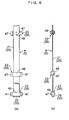
- the link mechanism 4 has one continuous flexible belt-shaped body 21 and shaft members 23 to which the belt-shaped body 21 is secured and which are each rotatably connected to the end portion 6 of each arm member 22, which is the one end portion 6 of each slat supporting mechanism 8.
- the link mechanism 5 has one continuous flexible belt-shaped body 25 similar to the belt-shaped body 21, as well as shaft members 26 which are similar to the shaft members 23 and to which the belt-shaped body 25 is secured, each shaft member 26 being rotatably fitted in the end portion 7 of each arm member 22 , which is the other end portion 7 of each slat supporting mechanism 8.
- the belt-shaped body 21 is passed through the shaft members 23 which are rotatably fitted in the end portions 6 of the respective arm members 22 including the end portions 6 of the uppermost and lowermost arm members 22 , and is secured to the shaft members 23 at the respective passing positions.
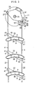
- the belt-shaped body 21 passed through the shaft member 23 fitted to the end portion 6 of the uppermost arm member 22 extends further to the tilting mechanism 11, and is inserted in and secured to a shaft member 28 of the tilting mechanism 11 at its upper end portion 27, as particularly shown in Fig. 3.
- the belt-shaped body 21 passed through the shaft member 23 fitted to the end portion 6 of the lowermost arm member 22 at its lower end portion 29 is secured to the shaft member 23 at that lower end portion 29 and terminates there.
- the belt-shaped body 25 is passed through the shaft members 26 which are rotatably fitted in the end portions 7 of the respective arm members 22 including the end portions 7 of the uppermost and lowermost arm members 22, and is secured to the shaft members 26 at the respective passing positions.
- the belt-shaped body 25 passed through the shaft member 26 fitted to the end portion 7 of the uppermost arm member 22 extends further to the tilting mechanism 11, and is inserted in and secured to a shaft member 32 of the tilting mechanism 11 at its upper end portion 31.
- the belt-shaped body 25 passed through the shaft member 26 fitted to the end portion 7 of the lowermost arm member 22 at its lower end portion 33 is secured to the shaft member 26 at that lower end portion 33 and terminates there.
- Each of the belt-shaped bodies 21 and 25 may be fabricated from a belt of a woven fabric or a knit fabric of yarn made of a synthetic resin such as polyester, or a flat belt of a nonwoven fabric made of a synthetic resin, or may be fabricated from another tough flexible belt.
- Each of the slat supporting mechanisms 8 has the arm member 22, a shaft portion 36 formed integrally with an arm body 35 of the arm member 22, a cover portion 37 formed integrally with the shaft portion 36, and a fitting portion 38 formed integrally in a substantially central portion of the cover portion 37.
- the shaft portion 36 is passed through the guide slit 15 and is disposed in and outside the vertical frame 2.
- the fitting portion 38 which is provided in the substantially central portion of the arm body 35 of the arm member 22 through the shaft portion 36 and the cover portion 37, is fitted in a hollow portion 40 in one end portion 39 of the slat 9 having a hollow body.
- the arm member 22 has the arm body 35 made of a synthetic resin and having a pair of split pins 41, as well as an arm plate 42 made of a metal or a resin and fitted to the arm body 35 through the split pins 41 of the arm body 35 in a snap-fit fashion.
- the shaft portion 36 is integrally provided in the substantially central portion of the arm body 35.
- the arm member 22 supports the end portion 39 of the slat 9 through the shaft portion 36, the cover portion 37, and the fitting portion 38 in its substantially central portion.
- Each of the shaft members 23 and 26 is formed by an integrally molded piece including a cylindrical portion 46 and a pair of shaft portions 47 which are integrally provided on opposite end faces of the cylindrical portion 46 disposed in such a manner as to be sandwiched between the arm body 35 and the arm plate 42 , and which are rotatably inserted in the arm body 35 and the arm plate 42.
- Each shaft member 23 or 26 is rotatably fitted at its shaft portion 47 in the end portion 6 or 7 of each arm member 22.
- Each of the belt-shaped bodies 21 and 25 is integrally secured to the cylindrical portion 46, and is passed through the cylindrical portion 46. The securing of each cylindrical portion 46 to each of the belt-shaped bodies 21 and 25 may be effected at the time of the integral molding of the shaft members 23 and 26.
- Each slat 9 comprises a hollow body, and its one end portion 39 is closed by the cover portion 37 of the slat supporting mechanism 8, while its other end portion 49 is closed by the cover portion 37 of the slat supporting mechanism 8 on the vertical frame 3 side.
- the respective slats 9 are supported at their opposite end portions 39 and 49 by the slat supporting mechanisms 8 on the vertical frame 2 side and the vertical frame 3 side so as to be parallel to each other in the opening P.
- the raising and lowering mechanism 10 includes a chain 51 disposed in each of the vertical frames 2 and 3 and serving as a flexible traveling body; a connecting mechanism 54 for connecting to the lowermost slat supporting mechanism 8 the other end portion 53 of the chain 51 having one end portion 52 which is a free end; a traveling unit 55 for causing the chain 51 to travel in directions A and B; and a guide mechanism 56 for guiding the traveling of the chain 51 in the directions A and B.
- the connecting mechanism 54 includes a pin member 61 disposed concentrically with the shaft portion 36 of the lowermost slat supporting mechanism 8 and secured to that shaft portion 36 in such a manner as to project from the arm plate 42; a connecting arm member 65 having one end portion 62 connected rotatably and linearly movably to the pin member 61 and the other end portion 63 connected rotatably to the end portion 53 of the chain 51 through a pin member 64; and a torsion coil spring 66 disposed between the chain 51 and the connecting arm member 65 and having one end portion retained by the end portion 53 of the chain 51, the other end portion retained by the connecting arm member 65, and a central portion wound around the pin member 64.
- the connecting arm member 65 has an elongated hole 67 with the pin member 61 inserted therein on the end portion 62 side.
- the connecting arm member 65 is rotatably and linearly movably connected to the pin member 61 on the end portion 62 side.
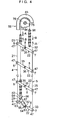
- the torsion coil spring 66 resiliently urges the connecting arm member 65 with respect to the end portion 53 of the chain 51 so as to rotate the connecting arm member 65 clockwise in Fig. 4 with respect to the end portion 53 of the chain 51. Consequently, the lowermost arm member 22 is adapted to be moved downward along the guide slit 15 by means of the pin member 61.
- the traveling unit 55 has an electric motor 71 for generating a traveling force for the chain 51 as well as a transmitting means 72 for transmitting the traveling force from the electric motor 71 to the chain 51.
- the electric motor 71 supported on the vertical frame 2 through a speed reducer 73 and a bracket 74 has a braking mechanism.
- the braking mechanism cancels the braking of the output rotating shaft of the electric motor 71 when electric power is supplied so as to rotate its output rotating shaft, and effects braking so as not to freely rotate the output rotating shaft when electric power is not supplied so as not to rotate the output rotating shaft.
- This braking mechanism is electromagnetically operated on supply of electric power to the electric motor 71 to cancel the braking of the output rotating shaft of the electric motor 71, and stops the electromagnetic operation on stopping of the supply of electric power to effect the braking of the output rotating shaft of the electric motor 71 by mechanical operation.
- the transmitting means 72 has the speed reducer 73 for reducing the rotational speed of the output rotating shaft of the electric motor 71; a rotating shaft 75 to which the rotation of the output rotating shaft of the speed reducer 73 is transmitted; and a sprocket wheel 76 secured to one end of the rotating shaft 75 and serving as a rotating body around which the chain 51 is wound.
- the rotating shaft 75 is rotatably supported at its respective end portions by a bracket 77 attached to each of the vertical frames 2 and 3.
- the sprocket wheel 76 is disposed between the bracket 77 and a rotating body 78 of the tilting mechanism 11, and a sprocket wheel similar to the sprocket wheel 76 is also secured to the other end portion of the rotating shaft 75 on the vertical frame 3 side.
- the chain 51 disposed in the vertical frame 2 is wound around the sprocket wheel on the other end portion side of the rotating shaft 75.
- the transmitting means 72 is adapted to transmit the torque of the output rotating shaft of the electric motor 71 to the chain 51 through the speed reducer 73, the rotating shaft 75, and the sprocket wheel 76 as the traveling force in the directions A and B.
- the output rotating shaft of the electric motor 71 is coupled to the rotating shaft 75 through the speed reducer 73, instead of indirectly coupling the output rotating shaft of the electric motor 71 to the rotating shaft 75 in this way, the output rotating shaft of the electric motor 71 may be directly coupled to the rotating shaft 75, or the output rotating shaft of the electric motor 71 may be used as the rotating shaft 75.
- the guide mechanism 56 has two pairs of guide walls 81 and 82 extending vertically and formed integrally on a sidewall portion 80 of the vertical frame 2, as well as chain guides 83 and 84 secured to the bracket 77 and disposed around the outer periphery of the sprocket wheel 76.
- the chain 51 travels by passing along the path between the respective pairs of guide walls 81 and 82, between the chain guide 83 and the sprocket wheel 76, and between the chain guides 83 and 84, and its deflection is prevented by the two pairs of guide walls 81 and 82 and the chain guides 83 and 84.
- the tilting mechanism 11 includes the rotating body 78 provided rotatably on the rotating shaft 75 by means of a bearing 90 (see Fig. 8); an attaching member 91 through which the rotating shaft 75 is passed and which is secured to the rotating body 78 so as to rotate together with the rotation of the rotating body 78; and a clutch mechanism 92 for causing the rotating body 78 to rotate as the chain 51 travels in the directions A and B.
- the clutch mechanism 92 has a pawl member 94 attached rotatably to the rotating body 78 through a shaft 93; an engaging pin 95 supported by the vertical frame 2 through a bracket or the like so as to allow the pawl member 94 to engage therewith; and an engaging projection 96 provided on the chain 51 and adapted to abut against the pawl member 94 so as to cancel the engagement of the pawl member 94 with the engaging pin 95.
- the pawl member 94 integrally has a pawl portion 98 having a recess 97 for engaging the engaging pin 95, as well as an abutment portion 99 (see Fig. 8) for abutting against the engaging projection 96.
- a notch 101 is formed in the rotating body 78 for allowing the engaging projection 96 to approach the abutment portion 99 for the abutment of the engaging projection 96 against the abutment portion 99.
- the clutch mechanism 92 rotates the pawl member 94 by the abutment of the engaging projection 96 against the abutment portion 99 to cancel the mutual engagement between the recess 97 of the pawl portion 98 and the engaging pin 95, thereby setting the rotating body 78 in a rotatable state. Subsequently, the rotating body 78 is rotated together with the traveling of the chain 51 in the direction A.
- the clutch mechanism 92 rotates the pawl member 94 by cancellation of the abutment of the engaging projection 96 against the abutment portion 99 to allow the recess 97 of the pawl portion 98 and the engaging pin 95 to engage each other.
- the rotating body 78 is thereby fixed to the vertical frame 2 by means of the engaging pin 95 so as to be unrotatable.
- the tilting mechanism 11 swings the attaching member 91 counterclockwise in Fig. 3 by means of the rotating body 78, and lowers the upper end portion 27 of the belt-shaped body 21, while raising the upper end portion 31 of the belt-shaped body 25.
- the tilting mechanism 11 swings the attaching member 91 clockwise in Fig. 3 by means of the rotating body 78, and raises the upper end portion 27 of the belt-shaped body 21, while lowering the upper end portion 31 of the belt-shaped body 25.
- the respective slats 9 are tilted substantially vertically and completely close the opening P between the vertical frames 2 and 3.
- the sprocket wheel 76 is rotated by the rotation of the rotating shaft 75 through the speed reducer 73, thereby causing the chain 51 to travel in the direction B.
- the engaging projection 96 is also moved clockwise about the rotating shaft 75.
- the rotating body 78 is also moved or rotated clockwise, as shown in Fig. 9.
- the upper end portion 27 of the belt-shaped body 21 is pulled upward, while the upper end portion 31 of the belt-shaped body 25 is lowered downward.
- the end portion 6 of each arm member 22 is lifted upward relative to the end portion 7 thereof.
- each of the slats 9 are also rotated to the substantially horizontal position and set in the form of a rattan blind, as shown in Figs. 1, 3 and 4.
- the engaging projection 96 starts to be disengaged from the notch 101, and as the engaging projection 96 is disengaged from the notch 101, the engaging projection 96 then abuts against the pawl portion 98 and rotates the pawl member 94 about the shaft 93, causing the recess 97 of the pawl portion 98 and the engaging pin 95 to engage with each other. As shown in Fig. 8, as the recess 97 of the pawl portion 98 is engaged with the engaging pin 95, the rotation of the rotating body 78 is prevented and is held in that state.
- the lowermost arm member 22 connected to the end portion 53 of the chain 51 by the connecting mechanism 54 starts to be raised.
- the belt-shaped bodies 21 and 25 start to be deflected from their lower portions, and the slats 9 are consecutively superposed on top of each other starting with the lower ones, as shown in Fig. 11.
- the deflected belt-shaped bodies 21 and 25 are shown jutting out in the lateral direction due to their slight resiliency for the sake of explanation, in a case where they practically do not have resiliency, they droop down.
- the chain 51 is caused to travel in the direction A.
- the belt -shaped bodies 21 and 25 start to be extended beginning with their uppermost portions, and the superposition of the slats 9 starts to be canceled beginning with the upper ones.
- the engaging projection 96 starts to be inserted in the notch 101, as shown in Fig. 8. As a result of this insertion, as shown in Fig.
- the slats 9 which are supported by the belt-shaped bodies 21 and 25 by means of the slat supporting mechanisms 8 are thereby tilted in the opposite direction, and completely close the opening P, as shown in Fig. 7. Subsequently, the operation of the electric motor 71 is stopped by a signal from the detector or the like, and the state in which the opening P is completely closed is maintained.
- the operation of the electric motor 71 is not stopped immediately. Even if the chain 51 is further made to travel slightly in the direction A, the connecting arm member 65 itself connected rotatably to the end portion 53 of the chain 51 through the pin member 64 rotates about the pin member 61 against the resiliency of the torsion coil spring 66, and linearly moves with respect to the pin member 61. This arrangement ensures that further downward movement of the lowermost arm member 22 does not occur.
- the link mechanisms 4 and 5 are respectively comprised of the flexible belt-shaped bodies 21 and 25 and the shaft members 23 and 26 to which the belt-shaped bodies 21 and 25 are secured and which are rotatably connected to the end portions 6 and 7 of the respective arm members 22, instead of a pair of chains of rigid link members which are linked in chain forms so as to be rotatable by means of shafts. Therefore, the link mechanisms 4 and 5 can be assembled in a short time. Moreover, the link mechanisms 4 and 5 can be made lightweight, so that not a very large force is required for raising and lowering the slats 9, thereby making it possible to easily effect the raising and lowering of the slats 9.
- the traveling body is not limited to the chain 51 with ends having the end portions 53 and 52, and may be an endless chain. In that case, it suffices if another sprocket wheel disposed in addition to the sprocket wheel 76, and the endless chain is wound around and trained between the two sprocket wheels.
- the guide mechanism 56 can be omitted if such an endless chain is used as the traveling body.
- a timing belt or the like may be used as the traveling body. In the case where the timing belt is used, it suffices if a toothed pulley is used instead of the sprocket wheel 76.
- the transmitting means 72 may be configured by omitting the speed reducer 73, in which case an electric motor 71 whose speed is controllable may be used, as required.
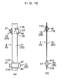
- each of the shaft members 23 and 26 may be formed by an integrally molded piece made of a synthetic resin and having, in addition to the cylindrical portion 46 and the shaft portion 47, a pair of rectangular projecting portions 115 and 116 disposed symmetrically about the axis of the cylindrical portion 46 and formed integrally with the cylindrical portion 46.
- each of the belt-shaped bodies 21 and 25 is integrally secured to the cylindrical portion 46 and the pair of rectangular projecting portions 115 and 116, and is passed through the cylindrical portion 46 and the pair of rectangular projecting portions 115 and 116 .
- the link mechanisms 4 and 5 are respectively formed by the two continuous belt-shaped bodies 21 and 25 in the above-described embodiment, the link mechanisms 4 and 5 may be alternatively formed by respectively having a plurality of belt-shaped pieces 111 and 112 which are respectively terminated inside the shaft members 23 and 26 respectively fitted rotatably in the corresponding end portions 6 and 7 of pairs of vertically adjacent arm members 22, as shown in Figs. 13(a) and 13(b).
- the belt-shaped pieces 111 and 112 excluding upper end portions 113 (corresponding to the upper end portions 27 and 31) of the uppermost belt-shaped pieces 111 and 112 and lower end portions 114 (corresponding to the lower end portions 29 and 33) of the lowermost belt-shaped pieces 111 and 112 are secured to the respective cylindrical portions 46 of the shaft members 23 and 26 at their upper end portions 113 and lower end portions 114, and are terminated inside the cylindrical portions 46.
- the uppermost belt-shaped pieces 111 and 112 are secured to the shaft members 28 and 32 at their upper end portions 113, while the lowermost belt-shaped pieces 111 and 112 are secured at their lower end portions 114 to the respective cylindrical portions 46 of the lowermost shaft members 23 and 26, and are terminated inside the cylindrical portions 46.
- the shaft members 23 and 26 such as those shown in Figs. 12(a) and 12(b) are used.
- the arrangement provided is such that the slats 9 are consecutively raised starting with the lowermost one by raising the arm member 22 of the lowermost slat supporting mechanism 8 by the raising and lowering mechanism 10, so as to set the opening P in the open state.
- an arrangement may be provided such that, as shown in Figs. 14 and 15, the raising and lowering mechanism 10 is connected to the uppermost arm member 22 , and the slats 9 are consecutively raised starting with the uppermost one by raising the uppermost arm member 22, so as to set the opening P in the closed state.
- the end portion 53 of the chain 51 whose traveling in the directions A and B is guided by the guide mechanism 56 is rotatably connected to a pin member 121.
- the pin member 121 is disposed concentrically with the shaft portion 36 of the uppermost slat supporting mechanism 8, is secured to that shaft portion 36, and is provided in such a manner as to project from the arm plate 42.
- the end portion 53 is lowered or raised. This causes the arm member 22 of the uppermost slat supporting mechanism 8 to be similarly lowered or raised by means of the pin member 121.
- the arm member 22 of the lowermost slat supporting mechanism 8 is adapted to be resiliently pulled downward by a pulling mechanism 125 which includes a slider member 122 connected rotatably to the pin member 61 and disposed in the guide slit 15 so as to guide its vertical movement, as well as a coil spring 124 having one end connected to the slider member 122 and the other end connected to a bottom wall portion 123 of the vertical frame 2.
- a pulling mechanism 125 which includes a slider member 122 connected rotatably to the pin member 61 and disposed in the guide slit 15 so as to guide its vertical movement, as well as a coil spring 124 having one end connected to the slider member 122 and the other end connected to a bottom wall portion 123 of the vertical frame 2.
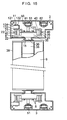
- the tilting mechanism 11 in the window blind apparatus 1 shown in Figs. 14 and 15 includes a cam roller 132 provided rotatably on a shaft member 131; a cam projection 134 provided integrally on a front wall portion 133 of the vertical frame 2; and a cam face member 136 provided integrally on the front wall portion 133 of the vertical frame 2 in such a manner as to extend vertically below the cam projection 134 with a recess 135 formed therebetween.
- the shaft member 131 is disposed concentrically with the shaft member 23 on the end portion 6 side of the uppermost arm member 22, is secured to the shaft portion 47 of that shaft member 23, and is provided projectingly from the arm plate 42.
- the upper end portion 27 of the belt-shaped body 21 of the link mechanism 4 is secured to the uppermost shaft member 23 and is terminated inside the cylindrical portion 46 of that shaft member 23.
- the upper end portion 31 of the belt-shaped body 25 of the link mechanism 5 is secured to the uppermost shaft member 26 and is terminated inside the cylindrical portion 46 of that shaft member 26.
- the belt-shaped bodies 21 and 25 are deflected, the cam roller 132 is in contact with the cam face member 136, and the respective slats 9 are closely superposed on top of each other (stacked) in a lower position.
- the electric motor 71 is first operated, and as its output rotating shaft rotates, the sprocket wheel 76 is rotated. This causes the chain 51 to travel in the direction B, and the belt-shaped bodies 21 and 25 are extended from their upper end sides, so that the arm members 22 are also raised upward starting with the uppermost one, as shown in Fig. 17.
- the belt-shaped bodies 21 and 25 are fully extended at a position immediately before the complete closure of the opening P. Meanwhile, the lowermost arm member 22 is slightly raised against the resiliency of the coil spring 124 by means of the belt-shaped bodies 21 and 25. Then, when the cam roller 132 faces the recess 135 and undergoes a shift from abutment against the cam face member 136 to abutment against the cam projection 134, as shown in Fig. 16, the uppermost arm member 22 starts to be rotated, and the upper end portion 31 of the belt-shaped body 25 comes to be lifted more than the upper end portion 27 of the belt-shaped body 21.
- the uppermost slat 9 is rotated counterclockwise, and the counterclockwise rotation of the uppermost arm member 22 is transmitted to the lower arm members 22 by means of the belt-shaped body 21 and the belt-shaped body 25, thereby holding all the slats 9 in a substantially vertically tilted state.
- the opening P is fully closed by the slats 9.
- the operation of the electric motor 71 is stopped, and the closing operation is completed. Even if the stopping of the operation of the electric motor 71 is slightly delayed, and the lowermost arm member 22 is pulled further upward in a state where the belt-shaped bodies 21 and 25 are fully extended, the lowermost slider member 122 urged resiliently downward by the coil spring 124 moves upward. Therefore, even if the stopping of the operation of the electric motor 71 is delayed, the belt-shaped bodies 21 and 25 do not become damaged.
- the electric motor 71 When the opening P is opened, the electric motor 71 is operated in the opposite direction to the one described above, and the cam roller 132 thereby undergoes a shift from abutment against the cam projection 134 to abutment against the cam face member 136, consecutively deflecting the belt-shaped bodies 21 and 25 starting with their lower portions.
- the link mechanisms 4 and 5 are respectively comprised of the flexible belt-shaped bodies 21 and 25 as well as the shaft members 23 and 26 in which the belt-shaped bodies 21 and 25 are inserted and secured and which are rotatably connected to the end portions 6 and 7 of the respective arm members 22. Therefore, the link mechanisms 4 and 5 can be assembled in a short time. Moreover, the link mechanisms 4 and 5 can be made lightweight, so that not a very large force is required for raising and lowering the slats 9, thereby making it possible to easily effect the raising and lowering of the slats 9.
- the electric motor 71 is provided to raise the slats 9 automatically
- the raising and lowering mechanism 10 may be alternatively arranged to raise the slats 9 manually.
- the window blind apparatus 1 is constructed by using the slats 9 formed of hollow bodies
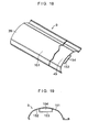
- the window blind apparatus 1 may be alternatively constructed by using the slats 9 each having a plate-like curved slat body 151 and a hollow rectangular portion 153 formed integrally on one surface 152 of the slat body 151, as shown in Figs. 18 and 19.
- the fitting portion 38 of the slat supporting mechanism 8 is fitted in a hollow portion 154 formed by the rectangular portion 153 in each of the end portions 39 and 49 of the slat 9 shown in Figs. 18 and 19, so as to support such a slat 9.
Landscapes
- Engineering & Computer Science (AREA)
- Structural Engineering (AREA)
- Civil Engineering (AREA)
- Architecture (AREA)
- Blinds (AREA)
- Specific Sealing Or Ventilating Devices For Doors And Windows (AREA)
Abstract
Description
- The present invention relates to a blind apparatus disposed in an opening such as a window of a building to open or close the opening.
- The present assignee earlier proposed a blind apparatus disclosed in JP-A-8-326445.
- The aforementioned blind apparatus is comprised of a pair of link mechanisms; a plurality of slat supporting mechanisms each having one end portion connected to one of the link mechanisms and the other end portion connected to the other link mechanism; slats respectively supported by the slat supporting mechanisms; a raising and lowering mechanism for raising and lowering the slats; and a tilting mechanism for tilting the slats by causing the pair of link mechanisms to undergo relative positional changes as the slats are raised or lowered by the raising and lowering mechanism. Each of the slat supporting mechanisms has an arm member for supporting an end portion of the slat at a substantially central portion of the arm member.
- With the blind apparatus disclosed in the above-described publication, since each of the link mechanisms is formed by linking plate-shaped rigid link members in a chain form by means of shafts, substantial time is required for the assembly of the link mechanisms, and a large force is required for raising and lowering the slats due to the weight of the link members.
- The present invention has been devised in view of the above-described aspects, and its object is to provide a blind apparatus which makes it possible to assemble the link mechanisms in a short time, and make the link mechanisms lightweight so as to render needless a very large force for raising and lowering the slats, thereby making it possible to easily effect the raising and lowering of the slats.
- In accordance with a first aspect of the invention, there is provided a blind apparatus comprising: a first link mechanism; a second link mechanism juxtaposed to the first link mechanism; a plurality of slat supporting mechanisms each having one end portion connected to the first link mechanism and another end portion connected to the second link mechanism; slats respectively supported by the slat supporting mechanisms; a raising and lowering mechanism for raising and lowering the slats; and a tilting mechanism for tilting the slats by causing the first and the second link mechanisms to undergo relative positional changes as the slats are raised or lowered by the raising and lowering mechanism, each of the slat supporting mechanisms having an arm member for supporting an end portion of the slat at a substantially central portion of the arm member, the first link mechanism having a flexible belt-shaped body and shaft members to which the belt-shaped body is secured and which are each rotatably connected to one end portion of each of the arm members, the second link mechanism having a flexible belt-shaped body and shaft members to which the belt-shaped body is secured and which are each rotatably connected to another end portion of each of the arm members.
- According to the blind apparatus in accordance with the first aspect of the invention, the link mechanisms are respectively comprised of the flexible belt-shaped bodies and the shaft members to which the belt-shaped bodies are secured and which are rotatably connected to the end portions of the respective arm members, instead of a pair of chains of rigid link members which are linked in chain forms so as to be rotatable by means of shafts. Therefore, each of the link mechanisms can be assembled in a short time. Moreover, each of the link mechanisms can be made lightweight, so that not a very large force is required for raising and lowering the slats, thereby making it possible to easily effect the raising and lowering of the slats.
- Preferably, as in the blind apparatus in accordance with a second aspect of the invention, each of the belt-shaped bodies may be fabricated from one continuous belt-shaped member, and the belt-shaped member may be passed through shaft members which are respectively fitted rotatably in corresponding end portions of the arm members.
- Each belt-shaped body is sufficient if it is tough and flexible, and may not have very large elasticity. It is rather preferred that each belt-shaped body be nonelastic. As for the resiliency, each belt-shaped body may be slightly resilient, but it is rather preferred that the belt-shaped body not be resilient. Preferably, as in the blind apparatus in accordance with a third aspect of the invention, each of the belt-shaped bodies may be fabricated from a belt of a woven fabric or a knit fabric of yarn made of a synthetic resin such as polyester, or a belt of a nonwoven fabric made of a synthetic resin. In the invention, each of the belt-shaped bodies may be alternatively fabricated from a flat belt made of such as leather. As the yarn made of a synthetic resin, yarn made of polyester is preferable. As a more preferable example, it is possible to cite a flexible belt-shaped body made by plain weaving using such polyester-made yarn and having a width of 6 to 12 mm and a thickness of 0. 4 mm to 0. 7 mm, more specifically a width of 7 mm and a thickness of 0.6 mm.
- Preferably, as in the blind apparatus in accordance with a fourth aspect of the invention, each of the shaft members may be formed by an integrally molded piece made of a synthetic resin and including a cylindrical portion and a pair of shaft portions respectively disposed on opposite end faces of the cylindrical portion, and may be rotatably fitted at the shaft portion thereof in the corresponding end portion of each of the arm members. In this case, each of the belt-shaped bodies may be integrally secured to the cylindrical portion and passed through the cylindrical portion.
- In the case where each of the shaft members is formed by an integrally molded piece made of a synthetic resin, as in the blind apparatus in accordance with the fourth aspect of the invention, the securing of each shaft member to the belt-shaped body may be effected simultaneously with the integral molding of each shaft member by clamping the belt-shaped body between a pair of mold halves for integrally forming the shaft members, and by allowing a forming material of the shaft members to flow into the pair of mold halves with the belt-shaped body clamped therebetween.
- As in the blind apparatus in accordance with a fifth aspect of the invention, each shaft member in the blind apparatus in accordance with the fourth aspect may be formed by an integrally molded piece made of a synthetic resin and further having a pair of rectangular projecting portions disposed at symmetrical positions with respect to an axis of the cylindrical portion. In this case, each of the belt-shaped bodies may be integrally secured to the cylindrical portion and the pair of rectangular projecting portions, and may be passed through the cylindrical portion and the pair of rectangular projecting portions.
- Also in the case of the shaft member having the pair of rectangular projecting portions, the securing of each shaft member to the belt-shaped body may be effected simultaneously with the integral molding of each shaft member by clamping the belt-shaped body between the pair of mold halves for integrally forming the shaft members, and by allowing a forming material of the shaft members to flow into the pair of mold halves with the belt-shaped body clamped therebetween, as described above.
- In addition, as in the blind apparatus in accordance with a sixth aspect of the invention, each of the belt-shaped bodies may alternatively have a plurality of belt-shaped pieces which are respectively terminated inside shaft members respectively fitted rotatably in corresponding end portions of pairs of vertically adjacent ones of the arm members.
- As in the blind apparatus in accordance with a seventh aspect of the invention, each of the slats in a preferred example has a hollow portion, wherein each of the slat supporting mechanisms may further have a fitting portion provided in a substantially central portion of each of the arm members and fitted in the hollow portion in the end portion of each of the slats.
- In the blind apparatus in accordance with an eighth aspect of the invention, each of the arm members has an arm body made of a synthetic resin and an arm plate fitted to the arm body in a snap-fit fashion, each of the shaft members being disposed in such a manner as to be sandwiched between the arm body and the arm plate.
- In the present invention, as in the blind apparatus in accordance with a ninth aspect of the invention, the raising and lowering mechanism may be connected to a lowermost one of the arm members, and may be adapted to raise the slats by raising the lowermost one of the arm members. Alternatively, as in the blind apparatus in accordance with a 10th aspect of the invention, the raising and lowering mechanism may be connected to an uppermost one of the arm members, and may be adapted to raise the slats by raising the uppermost one of the arm members.
- In accordance with the present invention, it is possible to provide a blind apparatus which makes it possible to assemble the link mechanisms in a short time, and make the link mechanisms lightweight so as to render needless a very large force for raising and lowering the slats, thereby making it possible to easily effect the raising and lowering of the slats.
- Hereafter, a detailed description will be given of the present invention and embodiments thereof on the basis of the preferred embodiments shown in the drawings. It should be noted that the present invention is not limited to these embodiments.
-
- Fig. 1 is a perspective view of a preferred embodiment of the invention;
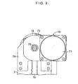
- Fig. 2 is a partial side elevational view of the embodiment shown in Fig. 1;
- Fig. 3 is an explanatory side elevational view of slats and components within one vertical frame in accordance with the embodiment shown in Fig. 1;
- Fig. 4 is an explanatory side elevational view of components within one vertical frame in accordance with the embodiment shown in Fig. 1;
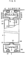
- Fig. 5 is an explanatory plan view of the embodiment shown in Fig. 1;
- Figs. 6(a) and 6(b) are explanatory diagrams of a link mechanism in accordance with the embodiment shown in Fig. 1, in which Fig. 6(a) is an explanatory front elevational view thereof, and Fig. 6(b) is an explanatory side elevational view thereof;
- Fig. 7 is a diagram explaining the operation of the embodiment shown in Fig. 1;
- Fig. 8 is a diagram explaining the operation of the embodiment shown in Fig. 1;
- Fig. 9 is a diagram explaining the operation of the embodiment shown in Fig. 1;
- Fig. 10 is a diagram explaining the operation of the embodiment shown in Fig. 1;
- Fig. 11 is a diagram explaining the operation of the embodiment shown in Fig. 1;
- Figs. 12 (a) and 12 (b) are explanatory diagrams of another example of the link mechanism in accordance with the embodiment shown in Fig. 1, in which Fig. 12(a) is an explanatory front elevational view thereof, and Fig. 12 (b) is an explanatory side elevational view thereof;
- Figs. 13(a) and 13(b) are explanatory diagrams of still another example of the link mechanism in accordance with the embodiment shown in Fig. 1, in which Fig. 13(a) is an explanatory front elevational view thereof, and Fig. 13(b) is an explanatory side elevational view thereof;
- Fig. 14 is an explanatory diagram of another example of a raising and lowering mechanism and a tilting mechanism shown in Fig. 1;
- Fig. 15 is an explanatory plan view of the another example of the raising and lowering mechanism and the tilting mechanism shown in Fig. 14;
- Fig. 16 is a diagram explaining the operation of the embodiment shown in Figs. 14 and 15;
- Fig. 17 is a diagram explaining the operation of the embodiment shown in Figs. 14 and 15;
- Fig. 18 is an explanatory perspective view of another example of the slat used in the blind apparatus in accordance with the invention; and
- Fig. 19 is an explanatory cross-sectional view of the embodiment shown in Fig. 18.
- In Figs. 1 to 6, a window blind apparatus 1 in accordance with this embodiment is comprised of a pair of
vertical frames link mechanism 4; alink mechanism 5 juxtaposed to thelink mechanism 4; a plurality of slat supportingmechanisms 8 each having oneend portion 6 connected to thelink mechanism 4 and theother end portion 7 connected to thelink mechanism 5; a plurality ofslats 9 supported by the respective slat supportingmechanisms 8 and juxtaposed in an opening P between thevertical frames mechanism 10 for raising and lowering theslats 9; and atilting mechanism 11 for tilting therespective slats 9 by causing thelink mechanisms slats 9 are raised or lowered by the raising andlowering mechanism 10. - The
vertical frame 2 , which is hollow, has aguide slit 15 extending in the vertical direction, while thevertical frame 3 , which is hollow, also has aguide slit 16 extending in the vertical direction. Thelink mechanisms tilting mechanism 11 are accommodated in the respectivevertical frames link mechanisms tilting mechanism 11 on thevertical frame 3 side are arranged in the same way as thelink mechanisms tilting mechanism 11 on thevertical frame 2 side, a detailed description will be given hereafter of thelink mechanisms tilting mechanism 11 on thevertical frame 2 side. - The
link mechanism 4 has one continuous flexible belt-shaped body 21 andshaft members 23 to which the belt-shaped body 21 is secured and which are each rotatably connected to theend portion 6 of eacharm member 22, which is the oneend portion 6 of each slat supportingmechanism 8. - In the same way as the
link mechanism 4 , thelink mechanism 5 has one continuous flexible belt-shaped body 25 similar to the belt-shaped body 21, as well asshaft members 26 which are similar to theshaft members 23 and to which the belt-shaped body 25 is secured, eachshaft member 26 being rotatably fitted in theend portion 7 of eacharm member 22 , which is theother end portion 7 of eachslat supporting mechanism 8. - As particularly shown in Figs. 6(a) and 6(b), the belt-
shaped body 21 is passed through theshaft members 23 which are rotatably fitted in theend portions 6 of therespective arm members 22 including theend portions 6 of the uppermost andlowermost arm members 22 , and is secured to theshaft members 23 at the respective passing positions. The belt-shapedbody 21 passed through theshaft member 23 fitted to theend portion 6 of theuppermost arm member 22 extends further to thetilting mechanism 11, and is inserted in and secured to ashaft member 28 of thetilting mechanism 11 at itsupper end portion 27, as particularly shown in Fig. 3. The belt-shapedbody 21 passed through theshaft member 23 fitted to theend portion 6 of thelowermost arm member 22 at itslower end portion 29 is secured to theshaft member 23 at thatlower end portion 29 and terminates there. - In the same way as the belt-shaped
body 21, the belt-shapedbody 25 is passed through theshaft members 26 which are rotatably fitted in theend portions 7 of therespective arm members 22 including theend portions 7 of the uppermost andlowermost arm members 22, and is secured to theshaft members 26 at the respective passing positions. The belt-shapedbody 25 passed through theshaft member 26 fitted to theend portion 7 of theuppermost arm member 22 extends further to thetilting mechanism 11, and is inserted in and secured to ashaft member 32 of thetilting mechanism 11 at itsupper end portion 31. The belt-shapedbody 25 passed through theshaft member 26 fitted to theend portion 7 of thelowermost arm member 22 at itslower end portion 33 is secured to theshaft member 26 at thatlower end portion 33 and terminates there. - Each of the belt-shaped
bodies - Each of the
slat supporting mechanisms 8 has thearm member 22, ashaft portion 36 formed integrally with anarm body 35 of thearm member 22, acover portion 37 formed integrally with theshaft portion 36, and afitting portion 38 formed integrally in a substantially central portion of thecover portion 37. Theshaft portion 36 is passed through the guide slit 15 and is disposed in and outside thevertical frame 2. Thefitting portion 38, which is provided in the substantially central portion of thearm body 35 of thearm member 22 through theshaft portion 36 and thecover portion 37, is fitted in ahollow portion 40 in oneend portion 39 of theslat 9 having a hollow body. - The
arm member 22 has thearm body 35 made of a synthetic resin and having a pair ofsplit pins 41, as well as anarm plate 42 made of a metal or a resin and fitted to thearm body 35 through thesplit pins 41 of thearm body 35 in a snap-fit fashion. Theshaft portion 36 is integrally provided in the substantially central portion of thearm body 35. Thus thearm member 22 supports theend portion 39 of theslat 9 through theshaft portion 36, thecover portion 37, and thefitting portion 38 in its substantially central portion. - Each of the
shaft members cylindrical portion 46 and a pair ofshaft portions 47 which are integrally provided on opposite end faces of thecylindrical portion 46 disposed in such a manner as to be sandwiched between thearm body 35 and thearm plate 42 , and which are rotatably inserted in thearm body 35 and thearm plate 42. Eachshaft member shaft portion 47 in theend portion arm member 22. Each of the belt-shapedbodies cylindrical portion 46, and is passed through thecylindrical portion 46. The securing of eachcylindrical portion 46 to each of the belt-shapedbodies shaft members - Each
slat 9 comprises a hollow body, and its oneend portion 39 is closed by thecover portion 37 of theslat supporting mechanism 8, while itsother end portion 49 is closed by thecover portion 37 of theslat supporting mechanism 8 on thevertical frame 3 side. Therespective slats 9 are supported at theiropposite end portions slat supporting mechanisms 8 on thevertical frame 2 side and thevertical frame 3 side so as to be parallel to each other in the opening P. - The raising and lowering
mechanism 10 includes achain 51 disposed in each of thevertical frames mechanism 54 for connecting to the lowermostslat supporting mechanism 8 theother end portion 53 of thechain 51 having oneend portion 52 which is a free end; a traveling unit 55 for causing thechain 51 to travel in directions A and B; and aguide mechanism 56 for guiding the traveling of thechain 51 in the directions A and B. - Since the
chain 51, the connectingmechanism 54, and theguide mechanism 56 are respectively arranged in the same way on thevertical frame 2 side and thevertical frame 3 side, a derailed description will be given hereafter of thevertical frame 2 side. - The connecting
mechanism 54 includes apin member 61 disposed concentrically with theshaft portion 36 of the lowermostslat supporting mechanism 8 and secured to thatshaft portion 36 in such a manner as to project from thearm plate 42; a connectingarm member 65 having one end portion 62 connected rotatably and linearly movably to thepin member 61 and theother end portion 63 connected rotatably to theend portion 53 of thechain 51 through apin member 64; and atorsion coil spring 66 disposed between thechain 51 and the connectingarm member 65 and having one end portion retained by theend portion 53 of thechain 51, the other end portion retained by the connectingarm member 65, and a central portion wound around thepin member 64. - The connecting
arm member 65 has an elongatedhole 67 with thepin member 61 inserted therein on the end portion 62 side. As a result, the connectingarm member 65 is rotatably and linearly movably connected to thepin member 61 on the end portion 62 side. Thetorsion coil spring 66 resiliently urges the connectingarm member 65 with respect to theend portion 53 of thechain 51 so as to rotate the connectingarm member 65 clockwise in Fig. 4 with respect to theend portion 53 of thechain 51. Consequently, thelowermost arm member 22 is adapted to be moved downward along the guide slit 15 by means of thepin member 61. - The traveling unit 55 has an
electric motor 71 for generating a traveling force for thechain 51 as well as a transmitting means 72 for transmitting the traveling force from theelectric motor 71 to thechain 51. - The
electric motor 71 supported on thevertical frame 2 through aspeed reducer 73 and abracket 74 has a braking mechanism. The braking mechanism cancels the braking of the output rotating shaft of theelectric motor 71 when electric power is supplied so as to rotate its output rotating shaft, and effects braking so as not to freely rotate the output rotating shaft when electric power is not supplied so as not to rotate the output rotating shaft. This braking mechanism is electromagnetically operated on supply of electric power to theelectric motor 71 to cancel the braking of the output rotating shaft of theelectric motor 71, and stops the electromagnetic operation on stopping of the supply of electric power to effect the braking of the output rotating shaft of theelectric motor 71 by mechanical operation. - The transmitting means 72 has the
speed reducer 73 for reducing the rotational speed of the output rotating shaft of theelectric motor 71; arotating shaft 75 to which the rotation of the output rotating shaft of thespeed reducer 73 is transmitted; and asprocket wheel 76 secured to one end of therotating shaft 75 and serving as a rotating body around which thechain 51 is wound. - The rotating
shaft 75 is rotatably supported at its respective end portions by abracket 77 attached to each of thevertical frames sprocket wheel 76 is disposed between thebracket 77 and arotating body 78 of thetilting mechanism 11, and a sprocket wheel similar to thesprocket wheel 76 is also secured to the other end portion of therotating shaft 75 on thevertical frame 3 side. In the same way as thechain 51 disposed in thevertical frame 2 , thechain 51 disposed in thevertical frame 3 is wound around the sprocket wheel on the other end portion side of therotating shaft 75. - The transmitting means 72 is adapted to transmit the torque of the output rotating shaft of the
electric motor 71 to thechain 51 through thespeed reducer 73, the rotatingshaft 75, and thesprocket wheel 76 as the traveling force in the directions A and B. - In this embodiment, although the output rotating shaft of the
electric motor 71 is coupled to therotating shaft 75 through thespeed reducer 73, instead of indirectly coupling the output rotating shaft of theelectric motor 71 to therotating shaft 75 in this way, the output rotating shaft of theelectric motor 71 may be directly coupled to therotating shaft 75, or the output rotating shaft of theelectric motor 71 may be used as the rotatingshaft 75. - The
guide mechanism 56 has two pairs ofguide walls sidewall portion 80 of thevertical frame 2, as well as chain guides 83 and 84 secured to thebracket 77 and disposed around the outer periphery of thesprocket wheel 76. Thechain 51 travels by passing along the path between the respective pairs ofguide walls chain guide 83 and thesprocket wheel 76, and between the chain guides 83 and 84, and its deflection is prevented by the two pairs ofguide walls - The
tilting mechanism 11 includes therotating body 78 provided rotatably on therotating shaft 75 by means of a bearing 90 (see Fig. 8); an attachingmember 91 through which therotating shaft 75 is passed and which is secured to therotating body 78 so as to rotate together with the rotation of therotating body 78; and aclutch mechanism 92 for causing the rotatingbody 78 to rotate as thechain 51 travels in the directions A and B. - The
clutch mechanism 92 has apawl member 94 attached rotatably to therotating body 78 through ashaft 93; an engagingpin 95 supported by thevertical frame 2 through a bracket or the like so as to allow thepawl member 94 to engage therewith; and an engagingprojection 96 provided on thechain 51 and adapted to abut against thepawl member 94 so as to cancel the engagement of thepawl member 94 with the engagingpin 95. - The
pawl member 94 integrally has apawl portion 98 having arecess 97 for engaging the engagingpin 95, as well as an abutment portion 99 (see Fig. 8) for abutting against the engagingprojection 96. Anotch 101 is formed in therotating body 78 for allowing the engagingprojection 96 to approach theabutment portion 99 for the abutment of the engagingprojection 96 against theabutment portion 99. - In the traveling of the
chain 51 in the direction A, theclutch mechanism 92 rotates thepawl member 94 by the abutment of the engagingprojection 96 against theabutment portion 99 to cancel the mutual engagement between therecess 97 of thepawl portion 98 and the engagingpin 95, thereby setting therotating body 78 in a rotatable state. Subsequently, the rotatingbody 78 is rotated together with the traveling of thechain 51 in the direction A. Meanwhile, in the traveling of thechain 51 in the direction B opposite to the direction A, theclutch mechanism 92 rotates thepawl member 94 by cancellation of the abutment of the engagingprojection 96 against theabutment portion 99 to allow therecess 97 of thepawl portion 98 and the engagingpin 95 to engage each other. The rotatingbody 78 is thereby fixed to thevertical frame 2 by means of the engagingpin 95 so as to be unrotatable. - As the engaging
projection 96 abuts against theabutment portion 99 when thechain 51 travels in the direction A, thetilting mechanism 11 swings the attachingmember 91 counterclockwise in Fig. 3 by means of therotating body 78, and lowers theupper end portion 27 of the belt-shapedbody 21, while raising theupper end portion 31 of the belt-shapedbody 25. On the other hand, as the abutment of the engagingprojection 96 against theabutment portion 99 is canceled when thechain 51 travels in the direction B, thetilting mechanism 11 swings the attachingmember 91 clockwise in Fig. 3 by means of therotating body 78, and raises theupper end portion 27 of the belt-shapedbody 21, while lowering theupper end portion 31 of the belt-shapedbody 25. - In the above-described window blind apparatus 1, when the
chain 51 has traveled in the direction A, in the state in which, as shown in Fig. 10 , the engagingprojection 96 provided on thechain 51 is disposed in thenotch 101 and abuts against theabutment portion 99 of thepawl member 94 to lower theupper end portion 27 of the belt-shapedbody 21, while raising theupper end portion 31 of the belt-shapedbody 25, as shown in Fig. 7, thelowermost arm member 22 is urged downward by means of the connectingarm member 65 and thepin member 64 by thetorsion coil spring 66, and the belt-shapedbodies respective slats 9 are tilted substantially vertically and completely close the opening P between thevertical frames electric motor 71 is operated in this state, thesprocket wheel 76 is rotated by the rotation of therotating shaft 75 through thespeed reducer 73, thereby causing thechain 51 to travel in the direction B. - As the
chain 51 travels in the direction B, the engagingprojection 96 is also moved clockwise about the rotatingshaft 75. As the engagingprojection 96 is thus moved, the rotatingbody 78 is also moved or rotated clockwise, as shown in Fig. 9. As therotating body 78 is thus moved, theupper end portion 27 of the belt-shapedbody 21 is pulled upward, while theupper end portion 31 of the belt-shapedbody 25 is lowered downward. Thus, as the belt-shapedbodies end portion 6 of eacharm member 22 is lifted upward relative to theend portion 7 thereof. As therespective arm members 22 are thereby rotated clockwise, each of theslats 9 are also rotated to the substantially horizontal position and set in the form of a rattan blind, as shown in Figs. 1, 3 and 4. - As the
chain 51 is made to further travel in the direction B, the engagingprojection 96 starts to be disengaged from thenotch 101, and as the engagingprojection 96 is disengaged from thenotch 101, the engagingprojection 96 then abuts against thepawl portion 98 and rotates thepawl member 94 about theshaft 93, causing therecess 97 of thepawl portion 98 and the engagingpin 95 to engage with each other. As shown in Fig. 8, as therecess 97 of thepawl portion 98 is engaged with the engagingpin 95, the rotation of therotating body 78 is prevented and is held in that state. - As the
chain 51 continues to travel in the direction B, thelowermost arm member 22 connected to theend portion 53 of thechain 51 by the connectingmechanism 54 starts to be raised. At the same time, the belt-shapedbodies slats 9 are consecutively superposed on top of each other starting with the lower ones, as shown in Fig. 11. It should be noted that although, in Fig. 11, the deflected belt-shapedbodies slats 9 are completely superposed in an upper portion of the opening P, the operation of theelectric motor 71 is stopped by a signal from a detector or the like, and the state in which the opening P is completely open is maintained. - If the
electric motor 71 is operated in the opposite direction to the one described above in the state in which the opening P is completely open or in the state in which the opening P is halfway open, thechain 51 is caused to travel in the direction A. As a result, the belt -shapedbodies slats 9 starts to be canceled beginning with the upper ones. When the deflection of the belt-shapedbodies slats 9 is totally canceled, the engagingprojection 96 starts to be inserted in thenotch 101, as shown in Fig. 8. As a result of this insertion, as shown in Fig. 9, the engagingprojection 96 abuts against theabutment portion 99 of thepawl member 94 and rotates thepawl member 94, canceling the engagement of therecess 97 with the engagingpin 95. As a result of this cancellation, together with the movement of the engagingprojection 96 the rotatingbody 78 is rotated counterclockwise in the opposite direction to the one described above, as shown in Fig. 10. Hence, theupper end portion 31 of the belt-shapedbody 25 is pulled upward, while theupper end portion 27 of the belt-shapedbody 21 is pulled downward. As the belt-shapedbodies bodies slats 9 which are supported by the belt-shapedbodies slat supporting mechanisms 8 are thereby tilted in the opposite direction, and completely close the opening P, as shown in Fig. 7. Subsequently, the operation of theelectric motor 71 is stopped by a signal from the detector or the like, and the state in which the opening P is completely closed is maintained. - In the window blind apparatus 1, after the opening P has been completely closed, the operation of the
electric motor 71 is not stopped immediately. Even if thechain 51 is further made to travel slightly in the direction A, the connectingarm member 65 itself connected rotatably to theend portion 53 of thechain 51 through thepin member 64 rotates about thepin member 61 against the resiliency of thetorsion coil spring 66, and linearly moves with respect to thepin member 61. This arrangement ensures that further downward movement of thelowermost arm member 22 does not occur. - With the above-described window blind apparatus 1 having combinations of the
link mechanisms slat supporting mechanisms 8, thelink mechanisms bodies shaft members bodies end portions respective arm members 22, instead of a pair of chains of rigid link members which are linked in chain forms so as to be rotatable by means of shafts. Therefore, thelink mechanisms link mechanisms slats 9, thereby making it possible to easily effect the raising and lowering of theslats 9. - In the above-described embodiment, the traveling body is not limited to the
chain 51 with ends having theend portions sprocket wheel 76, and the endless chain is wound around and trained between the two sprocket wheels. Theguide mechanism 56 can be omitted if such an endless chain is used as the traveling body. In addition, a timing belt or the like may be used as the traveling body. In the case where the timing belt is used, it suffices if a toothed pulley is used instead of thesprocket wheel 76. In addition, the transmitting means 72 may be configured by omitting thespeed reducer 73, in which case anelectric motor 71 whose speed is controllable may be used, as required. - In addition, in the
link mechanisms bodies lower end portions shaft members shaft members bodies lower end portions cylindrical portions 46 of theshaft members shaft members cylindrical portion 46 and theshaft portion 47, a pair of rectangular projectingportions cylindrical portion 46 and formed integrally with thecylindrical portion 46. In this case, each of the belt-shapedbodies cylindrical portion 46 and the pair of rectangular projectingportions cylindrical portion 46 and the pair of rectangular projectingportions link mechanisms bodies link mechanisms pieces shaft members corresponding end portions adjacent arm members 22, as shown in Figs. 13(a) and 13(b). In this case, the belt-shapedpieces upper end portions 27 and 31) of the uppermost belt-shapedpieces lower end portions 29 and 33) of the lowermost belt-shapedpieces cylindrical portions 46 of theshaft members upper end portions 113 andlower end portions 114, and are terminated inside thecylindrical portions 46. The uppermost belt-shapedpieces shaft members upper end portions 113, while the lowermost belt-shapedpieces lower end portions 114 to the respectivecylindrical portions 46 of thelowermost shaft members cylindrical portions 46. In the case of such belt-shapedpieces shaft members - With the above-described window blind apparatus 1, the arrangement provided is such that the
slats 9 are consecutively raised starting with the lowermost one by raising thearm member 22 of the lowermostslat supporting mechanism 8 by the raising and loweringmechanism 10, so as to set the opening P in the open state. Alternatively, an arrangement may be provided such that, as shown in Figs. 14 and 15, the raising and loweringmechanism 10 is connected to theuppermost arm member 22 , and theslats 9 are consecutively raised starting with the uppermost one by raising theuppermost arm member 22, so as to set the opening P in the closed state. - Namely, with the raising and lowering
mechanism 10 in the window blind apparatus 1 shown in Figs. 14 and 15, theend portion 53 of thechain 51 whose traveling in the directions A and B is guided by theguide mechanism 56 is rotatably connected to apin member 121. Thepin member 121 is disposed concentrically with theshaft portion 36 of the uppermostslat supporting mechanism 8, is secured to thatshaft portion 36, and is provided in such a manner as to project from thearm plate 42. As thechain 51 travels in the direction A or B by the operation of theelectric motor 71, theend portion 53 is lowered or raised. This causes thearm member 22 of the uppermostslat supporting mechanism 8 to be similarly lowered or raised by means of thepin member 121. Here, thearm member 22 of the lowermostslat supporting mechanism 8 is adapted to be resiliently pulled downward by a pullingmechanism 125 which includes aslider member 122 connected rotatably to thepin member 61 and disposed in the guide slit 15 so as to guide its vertical movement, as well as acoil spring 124 having one end connected to theslider member 122 and the other end connected to abottom wall portion 123 of thevertical frame 2. - In addition, the
tilting mechanism 11 in the window blind apparatus 1 shown in Figs. 14 and 15 includes acam roller 132 provided rotatably on ashaft member 131; acam projection 134 provided integrally on afront wall portion 133 of thevertical frame 2; and acam face member 136 provided integrally on thefront wall portion 133 of thevertical frame 2 in such a manner as to extend vertically below thecam projection 134 with arecess 135 formed therebetween. Theshaft member 131 is disposed concentrically with theshaft member 23 on theend portion 6 side of theuppermost arm member 22, is secured to theshaft portion 47 of thatshaft member 23, and is provided projectingly from thearm plate 42. Theupper end portion 27 of the belt-shapedbody 21 of thelink mechanism 4 is secured to theuppermost shaft member 23 and is terminated inside thecylindrical portion 46 of thatshaft member 23. Meanwhile, theupper end portion 31 of the belt-shapedbody 25 of thelink mechanism 5 is secured to theuppermost shaft member 26 and is terminated inside thecylindrical portion 46 of thatshaft member 26. - In the window blind apparatus 1 shown in Figs. 14 and 15, in the state in which the opening P is open, as shown in Fig. 17, the belt-shaped
bodies cam roller 132 is in contact with thecam face member 136, and therespective slats 9 are closely superposed on top of each other (stacked) in a lower position. At the time of closing the opening P, theelectric motor 71 is first operated, and as its output rotating shaft rotates, thesprocket wheel 76 is rotated. This causes thechain 51 to travel in the direction B, and the belt-shapedbodies arm members 22 are also raised upward starting with the uppermost one, as shown in Fig. 17. Consequently, therespective slats 9 supported by thearm members 22 are consecutively raised in the closing direction. When thecam roller 132 is being guided in contact with thecam face member 136, theslats 9 are held in a substantially horizontally tilted state. - As the
chain 51 travels further in the direction B, the belt-shapedbodies lowermost arm member 22 is slightly raised against the resiliency of thecoil spring 124 by means of the belt-shapedbodies cam roller 132 faces therecess 135 and undergoes a shift from abutment against thecam face member 136 to abutment against thecam projection 134, as shown in Fig. 16, theuppermost arm member 22 starts to be rotated, and theupper end portion 31 of the belt-shapedbody 25 comes to be lifted more than theupper end portion 27 of the belt-shapedbody 21. Consequently, theuppermost slat 9 is rotated counterclockwise, and the counterclockwise rotation of theuppermost arm member 22 is transmitted to thelower arm members 22 by means of the belt-shapedbody 21 and the belt-shapedbody 25, thereby holding all theslats 9 in a substantially vertically tilted state. As a result, the opening P is fully closed by theslats 9. Subsequently, the operation of theelectric motor 71 is stopped, and the closing operation is completed. Even if the stopping of the operation of theelectric motor 71 is slightly delayed, and thelowermost arm member 22 is pulled further upward in a state where the belt-shapedbodies lowermost slider member 122 urged resiliently downward by thecoil spring 124 moves upward. Therefore, even if the stopping of the operation of theelectric motor 71 is delayed, the belt-shapedbodies - When the opening P is opened, the
electric motor 71 is operated in the opposite direction to the one described above, and thecam roller 132 thereby undergoes a shift from abutment against thecam projection 134 to abutment against thecam face member 136, consecutively deflecting the belt-shapedbodies - Also with the above-described window blind apparatus 1 shown in Figs. 14 and 15, the
link mechanisms bodies shaft members bodies end portions respective arm members 22. Therefore, thelink mechanisms link mechanisms slats 9, thereby making it possible to easily effect the raising and lowering of theslats 9. - Although, in the above-described raising and lowering
mechanism 10, theelectric motor 71 is provided to raise theslats 9 automatically, the raising and loweringmechanism 10 may be alternatively arranged to raise theslats 9 manually. - In addition, although the above-described window blind apparatus 1 is constructed by using the
slats 9 formed of hollow bodies, the window blind apparatus 1 may be alternatively constructed by using theslats 9 each having a plate-likecurved slat body 151 and a hollowrectangular portion 153 formed integrally on onesurface 152 of theslat body 151, as shown in Figs. 18 and 19. In this case, thefitting portion 38 of theslat supporting mechanism 8 is fitted in ahollow portion 154 formed by therectangular portion 153 in each of theend portions slat 9 shown in Figs. 18 and 19, so as to support such aslat 9. According to theslat 9 shown in Figs. 18 and 19, its further lightweight can be attained, so that not a very large force is required for raising and lowering theslats 9, thereby making it possible to easily effect the raising and lowering of theslats 9. Moreover, theslats 9 can be fabricated easily.
Claims (11)
- A blind apparatus comprising:a first link mechanism;a second link mechanism juxtaposed to said first link mechanism;a plurality of slat supporting mechanisms each having one end portion connected to said first link mechanism and another end connected to said second link mechanism;slats respectively supported by said slat supporting mechanisms;a raising and lowering mechanism for raising and lowering said slats; anda tilting mechanism for tilting said slats by causing said first and said second link mechanisms to undergo relative positional changes as said slats are raised or lowered by said raising and lowering mechanism,each of said slat supporting mechanisms having an arm member for supporting an end portion of said slat at a substantially central portion of said arm member,said first link mechanism having a flexible belt-shaped body and shaft members to which said belt-shaped body is secured and which are each rotatably connected to one end portion of each of said arm members,said second link mechanism having a flexible belt-shaped body and shaft members to which said belt-shaped body is secured and which are each rotatably connected to another end portion of each of said arm members.
- The blind apparatus according to claim 1, wherein each of said belt-shaped bodies is fabricated from one continuous belt-shaped member, and said belt-shaped member is passed through shaft members which are respectively fitted rotatably in corresponding end portions of said arm members.
- The blind apparatus according to claim 1 or 2, wherein each of said belt-shaped bodies is fabricated from a belt of a woven fabric or a knit fabric of yarn made of a synthetic resin such as polyester, or a belt of a nonwoven fabric made of a synthetic resin.
- The blind apparatus according to any one of claims 1 to 3, wherein each of said shaft members is formed by an integrally molded piece made of synthetic resin and including a cylindrical portion and a pair of shaft portions respectively disposed on opposite end faces of the cylindrical portion, and is rotatably fitted at the shaft portion thereof in the corresponding end portion of each of said arm members, each of said belt-shaped bodies being integrally secured to the cylindrical portion and passed through the cylindrical portion.
- The blind apparatus according to claim 4 , wherein each of said shaft members is formed by an integrally molded piece made of a synthetic resin and further having a pair of rectangular projecting portions disposed at symmetrical positions with respect to an axis of the cylindrical portion, and each of said belt-shaped bodies is integrally secured to the cylindrical portion and the pair of rectangular projecting portions, and is passed through the cylindrical portion and the pair of rectangular projecting portions.
- The blind apparatus according to claim 1, wherein each of said belt-shaped bodies has a plurality of belt-shaped pieces which are respectively terminated inside shaft members respectively fitted rotatably in corresponding end portions of pairs of vertically adjacent ones of said arm members.
- The blind apparatus according to any one of claims 1 to 6, wherein each of said slats has a hollow portion, and each of said slat supporting mechanisms further has a fitting portion provided in a substantially central portion of each of said arm members and fitted in the hollow portion in the end portion of each of said slats.
- The blind apparatus according to any one of claims 1 to 7, wherein each of said arm members has an arm body made of a synthetic resin and an arm plate fitted to the arm body in a snap-fit fashion, each of said shaft members being disposed in such a manner as to be sandwiched between the arm body and the arm plate.
- The blind apparatus according to any one of claims 1 to 8, wherein said raising and lowering mechanism is connected to a lowermost one of said arm members, and is adapted to raise said slats by raising the lowermost one of said arm members.
- The blind apparatus according to any one of claims 1 to 8, wherein said raising and lowering mechanism is connected to an uppermost one of said arm members, and is adapted to raise said slats by raising the uppermost one of said arm members.
- A combination of slat supporting mechanisms and first and second link mechanisms for use in the blind apparatus according to any one of claims 1 to 10, wherein each of said slat supporting mechanisms has an arm member for supporting an end portion of said slat at a substantially central portion of said arm member, and each of said link mechanisms has a flexible belt-shaped body and shaft members to which said belt-shaped body is secured and which are each rotatably connected to an end portion of each of said arm members.
Applications Claiming Priority (2)
| Application Number | Priority Date | Filing Date | Title |
|---|---|---|---|
| JP2002285550A JP3885701B2 (en) | 2002-09-30 | 2002-09-30 | Blind device |
| JP2002285550 | 2002-09-30 |
Publications (3)
| Publication Number | Publication Date |
|---|---|
| EP1403462A2 true EP1403462A2 (en) | 2004-03-31 |
| EP1403462A3 EP1403462A3 (en) | 2005-01-05 |
| EP1403462B1 EP1403462B1 (en) | 2011-01-12 |
Family
ID=31973398
Family Applications (1)
| Application Number | Title | Priority Date | Filing Date |
|---|---|---|---|
| EP03021679A Expired - Lifetime EP1403462B1 (en) | 2002-09-30 | 2003-09-29 | Blind apparatus |
Country Status (6)
| Country | Link |
|---|---|
| EP (1) | EP1403462B1 (en) |
| JP (1) | JP3885701B2 (en) |
| KR (1) | KR101035865B1 (en) |
| CN (1) | CN100470001C (en) |
| DE (1) | DE60335693D1 (en) |
| TW (2) | TWI343964B (en) |
Families Citing this family (9)
| Publication number | Priority date | Publication date | Assignee | Title |
|---|---|---|---|---|
| JP2007239387A (en) * | 2006-03-10 | 2007-09-20 | Ykk Ap株式会社 | Blind and fitting |
| WO2009022370A1 (en) * | 2007-08-14 | 2009-02-19 | Oiles Eco Corporation | Blind device |
| KR200453010Y1 (en) * | 2007-12-21 | 2011-03-31 | 조정환 | Rail Assembly |
| CN201358697Y (en) * | 2009-02-15 | 2009-12-09 | 张一飞 | Lift type anti-theft window shutter |
| KR101147331B1 (en) * | 2009-10-20 | 2012-05-22 | 정태락 | A blind and sun tracking apparatus |
| JP5953983B2 (en) * | 2012-06-28 | 2016-07-20 | オイレスEco株式会社 | Blind device |
| US10513879B2 (en) * | 2017-06-15 | 2019-12-24 | Taicang Kingfu Plastic Manufacture Co., Ltd. | Venetian blind |
| KR20190017308A (en) | 2017-08-10 | 2019-02-20 | 배종옥 | Folding furniture |
| CN107956727A (en) * | 2017-12-26 | 2018-04-24 | 信宜市汇美电器有限公司 | The ventilation fan that air inlet can be automatically closed |
Citations (1)
| Publication number | Priority date | Publication date | Assignee | Title |
|---|---|---|---|---|
| JPH08326445A (en) | 1995-03-28 | 1996-12-10 | Oiles Ind Co Ltd | Device for blind |
Family Cites Families (12)
| Publication number | Priority date | Publication date | Assignee | Title |
|---|---|---|---|---|
| US2391709A (en) * | 1943-08-27 | 1945-12-25 | Kasan Louis | Venetian blind |
| AT239509B (en) * | 1961-03-24 | 1965-04-12 | Andreas Kruell | Connection of straps with the slats of a blind |
| AT369130B (en) * | 1976-08-23 | 1982-12-10 | Griesser Ag | REEL SLAT STORE |
| CH650310A5 (en) * | 1981-04-27 | 1985-07-15 | Schenker Emil Ag | REEL SLAT STORE. |
| EP0179968B1 (en) * | 1984-10-30 | 1989-01-11 | Planya AG | Venetian blind |
| CH668617A5 (en) * | 1985-12-10 | 1989-01-13 | Baumann Rolladen | Slats gates. |
| JP3433557B2 (en) * | 1995-02-02 | 2003-08-04 | オイレス工業株式会社 | Blind equipment |
| JP3829446B2 (en) | 1997-11-26 | 2006-10-04 | オイレスEco株式会社 | Blind device |
| CA2224834C (en) * | 1997-12-15 | 2003-04-01 | Vinylbilt Shutters Systems Inc. | Louver control in a movable louver assembly |
| KR100326649B1 (en) | 1999-11-05 | 2002-03-02 | 최진순 | A window using for effective sun-visor or prevention of crimes |
| JP2002194966A (en) * | 2000-12-25 | 2002-07-10 | Nakamura:Kk | Elevating surface grid for emergency escape |
| EP1243744A1 (en) * | 2001-03-19 | 2002-09-25 | Dieter Niemann | Venetian blind drawn upwardly |
-
2002
- 2002-09-30 JP JP2002285550A patent/JP3885701B2/en not_active Expired - Lifetime
-
2003
- 2003-09-24 TW TW099110269A patent/TWI343964B/en not_active IP Right Cessation
- 2003-09-24 TW TW092126370A patent/TW200415298A/en not_active IP Right Cessation
- 2003-09-28 CN CNB031272126A patent/CN100470001C/en not_active Expired - Fee Related
- 2003-09-29 EP EP03021679A patent/EP1403462B1/en not_active Expired - Lifetime
- 2003-09-29 KR KR1020030067472A patent/KR101035865B1/en not_active Expired - Fee Related
- 2003-09-29 DE DE60335693T patent/DE60335693D1/en not_active Expired - Lifetime
Patent Citations (1)
| Publication number | Priority date | Publication date | Assignee | Title |
|---|---|---|---|---|
| JPH08326445A (en) | 1995-03-28 | 1996-12-10 | Oiles Ind Co Ltd | Device for blind |
Also Published As
| Publication number | Publication date |
|---|---|
| TWI343964B (en) | 2011-06-21 |
| EP1403462B1 (en) | 2011-01-12 |
| EP1403462A3 (en) | 2005-01-05 |
| TW200415298A (en) | 2004-08-16 |
| TW201030225A (en) | 2010-08-16 |
| CN1497125A (en) | 2004-05-19 |
| JP3885701B2 (en) | 2007-02-28 |
| KR101035865B1 (en) | 2011-05-20 |
| DE60335693D1 (en) | 2011-02-24 |
| JP2004124366A (en) | 2004-04-22 |
| TWI343963B (en) | 2011-06-21 |
| CN100470001C (en) | 2009-03-18 |
| KR20040028592A (en) | 2004-04-03 |
Similar Documents
| Publication | Publication Date | Title |
|---|---|---|
| EP1418306B1 (en) | Blind apparatus | |
| EP1403462B1 (en) | Blind apparatus | |
| RU2692850C1 (en) | Window curtain | |
| CN109424308B (en) | Venetian blind | |
| US20060162871A1 (en) | Screen device | |
| EP1418307A1 (en) | Blind apparatus | |
| TW201307667A (en) | Curtain with resistance balance mechanism | |
| CN112459666A (en) | Semi-automatic three-linkage door using gas spring and movable pulley | |
| US3862655A (en) | Transport mechanism for vertical venetian blinds and drapes | |
| JP7039408B2 (en) | Joinery | |
| JPH10196255A (en) | Locking mechanism of motor-driven shutter | |
| JP2902252B2 (en) | Vertical blind slat drive | |
| JP3921825B2 (en) | Blind device | |
| JP4085858B2 (en) | Shielding device | |
| JP4466639B2 (en) | Blind device | |
| JPH0988424A (en) | Open / close drive for vehicle automatic slide door | |
| JP3648811B2 (en) | Blind device | |
| JPH04150810A (en) | Shutter | |
| JP6505448B2 (en) | Double curtain device | |
| JP2013113054A (en) | Vertical blind device | |
| JPH0996177A (en) | Blind device | |
| JPS62148791A (en) | Electromotive pleated shade | |
| JPH08246765A (en) | Blind device | |
| JP2000017970A (en) | Blind device | |
| JPH04113697U (en) | Vertical blind device |
Legal Events
| Date | Code | Title | Description |
|---|---|---|---|
| PUAI | Public reference made under article 153(3) epc to a published international application that has entered the european phase |
Free format text: ORIGINAL CODE: 0009012 |
|
| AK | Designated contracting states |
Kind code of ref document: A2 Designated state(s): AT BE BG CH CY CZ DE DK EE ES FI FR GB GR HU IE IT LI LU MC NL PT RO SE SI SK TR |
|
| AX | Request for extension of the european patent |
Extension state: AL LT LV MK |
|
| RAP1 | Party data changed (applicant data changed or rights of an application transferred) |
Owner name: OILES ECO CORPORATION |
|
| PUAL | Search report despatched |
Free format text: ORIGINAL CODE: 0009013 |
|
| AK | Designated contracting states |
Kind code of ref document: A3 Designated state(s): AT BE BG CH CY CZ DE DK EE ES FI FR GB GR HU IE IT LI LU MC NL PT RO SE SI SK TR |
|
| AX | Request for extension of the european patent |
Extension state: AL LT LV MK |
|
| 17P | Request for examination filed |
Effective date: 20050614 |
|
| AKX | Designation fees paid |
Designated state(s): CH DE FR LI |
|
| 17Q | First examination report despatched |
Effective date: 20080519 |
|
| GRAP | Despatch of communication of intention to grant a patent |
Free format text: ORIGINAL CODE: EPIDOSNIGR1 |
|
| GRAS | Grant fee paid |
Free format text: ORIGINAL CODE: EPIDOSNIGR3 |
|
| GRAA | (expected) grant |
Free format text: ORIGINAL CODE: 0009210 |
|
| AK | Designated contracting states |
Kind code of ref document: B1 Designated state(s): CH DE FR LI |
|
| REG | Reference to a national code |
Ref country code: CH Ref legal event code: EP |
|
| REF | Corresponds to: |
Ref document number: 60335693 Country of ref document: DE Date of ref document: 20110224 Kind code of ref document: P |
|
| REG | Reference to a national code |
Ref country code: DE Ref legal event code: R096 Ref document number: 60335693 Country of ref document: DE Effective date: 20110224 |
|
| REG | Reference to a national code |
Ref country code: CH Ref legal event code: NV Representative=s name: BOVARD AG |
|
| PLBE | No opposition filed within time limit |
Free format text: ORIGINAL CODE: 0009261 |
|
| STAA | Information on the status of an ep patent application or granted ep patent |
Free format text: STATUS: NO OPPOSITION FILED WITHIN TIME LIMIT |
|
| 26N | No opposition filed |
Effective date: 20111013 |
|
| REG | Reference to a national code |
Ref country code: DE Ref legal event code: R097 Ref document number: 60335693 Country of ref document: DE Effective date: 20111013 |
|
| PGFP | Annual fee paid to national office [announced via postgrant information from national office to epo] |
Ref country code: FR Payment date: 20120926 Year of fee payment: 10 |
|
| REG | Reference to a national code |
Ref country code: FR Ref legal event code: ST Effective date: 20140530 |
|
| PG25 | Lapsed in a contracting state [announced via postgrant information from national office to epo] |
Ref country code: FR Free format text: LAPSE BECAUSE OF NON-PAYMENT OF DUE FEES Effective date: 20130930 |
|
| PGFP | Annual fee paid to national office [announced via postgrant information from national office to epo] |
Ref country code: CH Payment date: 20170912 Year of fee payment: 15 |
|
| PGFP | Annual fee paid to national office [announced via postgrant information from national office to epo] |
Ref country code: DE Payment date: 20170927 Year of fee payment: 15 |
|
| REG | Reference to a national code |
Ref country code: DE Ref legal event code: R119 Ref document number: 60335693 Country of ref document: DE |
|
| REG | Reference to a national code |
Ref country code: CH Ref legal event code: PL |
|
| PG25 | Lapsed in a contracting state [announced via postgrant information from national office to epo] |
Ref country code: DE Free format text: LAPSE BECAUSE OF NON-PAYMENT OF DUE FEES Effective date: 20190402 |
|
| PG25 | Lapsed in a contracting state [announced via postgrant information from national office to epo] |
Ref country code: CH Free format text: LAPSE BECAUSE OF NON-PAYMENT OF DUE FEES Effective date: 20180930 Ref country code: LI Free format text: LAPSE BECAUSE OF NON-PAYMENT OF DUE FEES Effective date: 20180930 |