EP1403456A1 - Door handle device - Google Patents
Door handle device Download PDFInfo
- Publication number
- EP1403456A1 EP1403456A1 EP20030256069 EP03256069A EP1403456A1 EP 1403456 A1 EP1403456 A1 EP 1403456A1 EP 20030256069 EP20030256069 EP 20030256069 EP 03256069 A EP03256069 A EP 03256069A EP 1403456 A1 EP1403456 A1 EP 1403456A1
- Authority
- EP
- European Patent Office
- Prior art keywords
- door handle
- vehicle
- handle device
- door
- chassis
- Prior art date
- Legal status (The legal status is an assumption and is not a legal conclusion. Google has not performed a legal analysis and makes no representation as to the accuracy of the status listed.)
- Withdrawn
Links
- 230000011664 signaling Effects 0.000 description 15
- 238000001514 detection method Methods 0.000 description 7
- 239000005357 flat glass Substances 0.000 description 6
- 230000004044 response Effects 0.000 description 4
- XLYOFNOQVPJJNP-UHFFFAOYSA-N water Substances O XLYOFNOQVPJJNP-UHFFFAOYSA-N 0.000 description 4
- 238000004078 waterproofing Methods 0.000 description 4
- 230000006870 function Effects 0.000 description 2
- 230000001012 protector Effects 0.000 description 2
- 229910001369 Brass Inorganic materials 0.000 description 1
- RYGMFSIKBFXOCR-UHFFFAOYSA-N Copper Chemical compound [Cu] RYGMFSIKBFXOCR-UHFFFAOYSA-N 0.000 description 1
- 238000013459 approach Methods 0.000 description 1
- 239000010951 brass Substances 0.000 description 1
- 239000004020 conductor Substances 0.000 description 1
- 229910052802 copper Inorganic materials 0.000 description 1
- 239000010949 copper Substances 0.000 description 1
- 230000002452 interceptive effect Effects 0.000 description 1
- 239000012528 membrane Substances 0.000 description 1
- 239000002184 metal Substances 0.000 description 1
- 229910052751 metal Inorganic materials 0.000 description 1
- 239000011347 resin Substances 0.000 description 1
- 229920005989 resin Polymers 0.000 description 1
- 238000003466 welding Methods 0.000 description 1
- 229910000859 α-Fe Inorganic materials 0.000 description 1
Images



Classifications
-
- E—FIXED CONSTRUCTIONS
- E05—LOCKS; KEYS; WINDOW OR DOOR FITTINGS; SAFES
- E05B—LOCKS; ACCESSORIES THEREFOR; HANDCUFFS
- E05B81/00—Power-actuated vehicle locks
- E05B81/54—Electrical circuits
- E05B81/64—Monitoring or sensing, e.g. by using switches or sensors
- E05B81/76—Detection of handle operation; Detection of a user approaching a handle; Electrical switching actions performed by door handles
-
- Y—GENERAL TAGGING OF NEW TECHNOLOGICAL DEVELOPMENTS; GENERAL TAGGING OF CROSS-SECTIONAL TECHNOLOGIES SPANNING OVER SEVERAL SECTIONS OF THE IPC; TECHNICAL SUBJECTS COVERED BY FORMER USPC CROSS-REFERENCE ART COLLECTIONS [XRACs] AND DIGESTS
- Y10—TECHNICAL SUBJECTS COVERED BY FORMER USPC
- Y10S—TECHNICAL SUBJECTS COVERED BY FORMER USPC CROSS-REFERENCE ART COLLECTIONS [XRACs] AND DIGESTS
- Y10S292/00—Closure fasteners
- Y10S292/25—Remote control
-
- Y—GENERAL TAGGING OF NEW TECHNOLOGICAL DEVELOPMENTS; GENERAL TAGGING OF CROSS-SECTIONAL TECHNOLOGIES SPANNING OVER SEVERAL SECTIONS OF THE IPC; TECHNICAL SUBJECTS COVERED BY FORMER USPC CROSS-REFERENCE ART COLLECTIONS [XRACs] AND DIGESTS
- Y10—TECHNICAL SUBJECTS COVERED BY FORMER USPC
- Y10T—TECHNICAL SUBJECTS COVERED BY FORMER US CLASSIFICATION
- Y10T292/00—Closure fasteners
- Y10T292/57—Operators with knobs or handles
-
- Y—GENERAL TAGGING OF NEW TECHNOLOGICAL DEVELOPMENTS; GENERAL TAGGING OF CROSS-SECTIONAL TECHNOLOGIES SPANNING OVER SEVERAL SECTIONS OF THE IPC; TECHNICAL SUBJECTS COVERED BY FORMER USPC CROSS-REFERENCE ART COLLECTIONS [XRACs] AND DIGESTS
- Y10—TECHNICAL SUBJECTS COVERED BY FORMER USPC
- Y10T—TECHNICAL SUBJECTS COVERED BY FORMER US CLASSIFICATION
- Y10T70/00—Locks
- Y10T70/50—Special application
- Y10T70/5889—For automotive vehicles
-
- Y—GENERAL TAGGING OF NEW TECHNOLOGICAL DEVELOPMENTS; GENERAL TAGGING OF CROSS-SECTIONAL TECHNOLOGIES SPANNING OVER SEVERAL SECTIONS OF THE IPC; TECHNICAL SUBJECTS COVERED BY FORMER USPC CROSS-REFERENCE ART COLLECTIONS [XRACs] AND DIGESTS
- Y10—TECHNICAL SUBJECTS COVERED BY FORMER USPC
- Y10T—TECHNICAL SUBJECTS COVERED BY FORMER US CLASSIFICATION
- Y10T70/00—Locks
- Y10T70/50—Special application
- Y10T70/5889—For automotive vehicles
- Y10T70/5973—Remote control
Definitions
- This invention generally relates to a door handle device. More particularly, this invention pertains to a door handle device applied to a vehicle door.
- a known door handle device is disclosed in a Japanese Patent Laid-open Publication No. 2002-30844.
- This door handle device includes a handle frame and a handle grip.
- the handle frame is fixed to an outer panel of a vehicle door.
- the handle grip is provided on the handle frame from the outside of a vehicle through the outer panel, and electrical components are included in the handle grip.
- the handle grip includes an antenna as one of the electrical components.
- the antenna transmits an identification signal with predetermined frequency to the outside of the vehicle.
- An oscillating circuit for keeping the antenna oscillating is provided between an inner panel of the vehicle door and a door trim through harness.
- the harness connecting the antenna to the oscillating circuit has to be provided so as not to interfere with the window glass.
- wiring structure between the antenna and the oscillating circuit cannot be simplified, and noise may be generated due to the complicated wiring structure.
- the present invention therefore seeks to provide a door handle device in which wiring structure between electric components provided within a door handle and a circuit connected to the electric components is simplified.
- a door handle device includes a frame fixed to the inside of an outer panel of a vehicle door and a grip provided on the frame from the outside of a vehicle and including an electrical component.
- the frame is integrally provided with a circuit electrically connected to the electrical component.
- the door handle device further includes a chassis integrally formed with the frame, and the circuit is provided within the chassis.
- a door handle device 10 according to the present Invention is applied to a smart entry system 50 (hereinafter referred to as a system 50).
- the system 50 is a door locking / unlocking system in which a vehicle door being in a locked state is switched to an unlocked state when an owner of a vehicle (hereinafter referred to as a user) is close to the vehicle and a hand of the user approaching the door handle device 10 is detected.
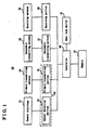
- the system 50 includes an primary transmitting antenna 54 (an electrical component) communicating with the outside of the vehicle and an secondary transmitting antenna 58 communicating with the inside of the vehicle.
- the primary transmitting antenna 54 is provided within the door handle device 10 (shown in Fig.3) mounted to a vehicle door 30 (shown in Fig.3), and the secondary transmitting antenna 56 is provided within an instrument panel in a vehicle compartment.
- the primary transmitting antenna 54 is connected to a primary transmitting portion 55, and the secondary transmitting antenna 56 is connected to a secondary transmitting portion 57.
- the primary transmitting portion 55 and the secondary transmitting portion 57 are connected to a controller 60.
- a sensor electrode 51 (an electrical component) is provided in the door handle device 10.
- the sensor electrode 51 detects the user approaching the vehicle door 30 based on variation of capacitance and connected to a sensor detection portion 53.
- the sensor detection portion 53 detects the user based on information from the sensor electrode 51 and connected to the controller 80.
- the sensor detection portion 53 and the primary transmitting portion 55 are integrally included in a single unit as a signaling circuit 52 (a circuit), and yet can be separatedly provided. Explanation concerning the signaling circuit 52 will be provided later.
- the controller 60 respectively transmits a primary request signal (hereinafter referred to as an outside request signal) and a secondary request signal (hereinafter referred to as an inside request signal) to the primary transmitting portion 55 and the secondary transmitting portion 57.
- a primary request signal hereinafter referred to as an outside request signal
- a secondary request signal hereinafter referred to as an inside request signal
- both antennae 54 and 56 transmit the request signals with frequency of 134kHz to a portable device 70 (shown in Fig.2).
- the vehicle is provided with a receiving antenna 58, and an identification signal outputted from the portable device 70 is received by the receiving antenna 58.
- the identification signal has frequency of 300MHz. This identification signal is demodulated at a receiving portion 59 and then inputted to the controller 60.
- the controller 60 is connected to a door lock device 62 provided on the vehicle door 30.
- a door lock device 62 switching between a locked state and an unlocked state Is performed by the controller 60.
- switches and sensors connected to the controller 60 for example, a courtesy switch which detects whether the vehicle door 30 is opened or closed to the vehicle
- detailed explanation is omitted.
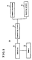
- Fig.2 shows a system configuration of the portable device 70 applied to the system 50.
- the portable device 70 includes a transmitting antenna 74 and a receiving antenna 75.
- the transmitting antenna 74 transmits the identification signal with frequency of 300MHz to the vehicle.
- the receiving antenna 75 receives the outsider inside request signals with frequency of 134kHz transmitted from the vehicle.
- the transmitting antenna 74 and the receiving antenna 75 are connected to a transceiving circuit 73.
- the transceiving circuit 73 is connected to a controller 71.
- the request signal from the vehicle received by the receiving antenna 75 is inputted to the controller 71 trough the transceiving circuit 73.
- the controller 71 transmits a response signal, which includes an identification code having been memorized in a memory 72, to the transceiving circuit 73 responding to the request signal.
- the response signal is modulated at the transceiving circuit 73 and then transmitted to the vehicle with frequency of 300MHz from the transmitting antenna 74.
- the door lock device 82 of the vehicle door 30 is In the locked state, If the user exists within a predetermined distance from the vehicle, the outside request signal transmitted from the primary transmitting antenna 54 can be transmitted to the receiving antenna 74 of the portable device 70 of the user. In the portable device 70, as described above, the controller 71 transmits the response signal responding to the outside request signal.
- the identification code demodulated by the receiving portion 59 is checked against an identification code having been memorized in a memory 61 by the controller 60. After the check between the identification codes is approved, the controller 60 is in an unlock standby state.
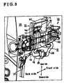
- Fig.3 shows a perspective view of the vehicle door 30 to which the door handle 10 is mounted.
- the vehicle door 30 is a swing-type vehicle door at a driver's seat.
- an outer panel of the vehicle door 30 Is omitted for the purpose of simplification.
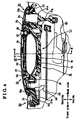
- the door handle 10 mainly includes a frame 11 and a grip 12. As shown in Fig.4, the frame 11 is fixed to the inside of an outer panel 31 of the vehicle door 30 by using two screws 32.
- the frame 11 is resinous and integrally includes a main frame 12 and a chassis 13, as shown in Figs.3-8 In detail.
- the main frame 12 extends In directions of the front and back side of the vehicle (a longitudinal direction of the vehicle), and the outside of the main frame 12 has a curved shape.
- This curved shape of the main frame 12 corresponds to a curved shape formed on the outer panel 31.
- the main frame 12 includes opening portions 12a and 12b at the front and back side of the vehicle respectively.
- an arm 21 a of a grip 20 (say later) is inserted
- a handle lever 21 b of the grip 20 (say later)
- a cylinder case portion 24 of a key cylinder 24 fixed to a cap 23 (say later) are Inserted.
- the chassis 13 mainly includes a case portion 14 and a cover portion 15.
- the case portion 14 further includes a base wall portion 14a, an upper wall portion 14b, and two lateral wall portions 14c.
- the base wall portion 14a is formed at an approximately middle part of the main frame 12 so as to have predetermined width along the longitudinal direction of the vehicle and to extend integrally upward from the main frame 12.
- the base wall portion 14a has a bended-shaped cross section, and an upper side of the base wall portion 14a is aslant outside (at an angle of ⁇ degrees to a perpendicular line).
- the upper wall portion 14b Is formed so as to extend outside from an upper end of the base wall portion 14a.
- each lateral wall portion 14c is formed so as to extend outside from both lateral ends of the base wall portion 14a.
- the case portion 14 includes an outer opening portion 14d opening outside.
- the cover portion 15 is fixed to the case portion 14 so that the outer opening 14d of the case portion 14 can be covered.
- An upper side of the cover portion 15 Is aslant outside so as to be parallel with the upper side of the base wall portion 14a, and an upper end 15a of the cover portion 15 is connected to the upper wall portion 14b.
- a connected portion 14e between the upper end 15a and the upper wall portion 14b has what we call a labyrinthine structure in which the upper end 15a is held between a pair of flanges formed so as to extend downward from the upper wall portion 14b. Further, the upper wall portion 14b extends outside beyond a position of the connected portion 14e.
- each lateral wall portion 14c is connected to both lateral ends of the cover portion 15 so that each lateral wall 14c can be held between a pair of flanges formed on the cover portion 15. That is, the lateral wall portions 14c are connected to the cover portion 15 by means of the labyrinthine structure in common with the connected portion 14e.
- a lower side of the cover portion 15 extends so as to face the main frame 12.
- the cover portion 15 is located outside at a predetermined distance from the main frame 12, and the chassis 13 includes a lower opening portion 13a opening downward.
- the grip 20 includes a base 21 and a cover 22 made from metal or resin.
- the cover 22 is fixed to the base 21 by using two screws 25, and a space is provided within the grip 20.
- the arm 21 a and the handle lover 21 b are formed at the front and back side of the grip 20 respectively.
- the grip 20 is assembled to the main frame 12 by inserting the handle lever 21 b in the opening portion 12b after the arm 21a is inserted in a receiving space 12c through the opening portion 12a of the main frame 12. Then, the grip 20 is fixed to the outer panel 31 of the vehicle door 30.
- the handle lever 21 b is connected to a cable 33 (shown in Fig.6) through a crank mechanism (not shown).
- the cable 33 is connected to an outside opening lever (not shown) operating the door lock device 62.
- the cap 23 Is fixed to the vehicle door 30 at the back side relative to the grip 20.
- the cap 23 is formed so that outer design of the cap 23 can be identical with that of the grip 20, and the key cylinder 24 and the cylinder case 24a are provided within the cap 23.
- the cylinder case 24a is directly connected to the door lock device 62 trough the opening portion 12b of the main frame 12, and then operation of the key cylinder 24 Is transmitted to the door lock device 62.
- the primary transmitting antenna 54, the sensor electrode 51, and a lock switch 26 are provided within the space of the grip 20.
- the primary transmitting antenna 54 is made of a ferrite core where wire is coiled so as to be biaxial and functions as a biaxial antenna.
- the sensor electrode 51 extends in the longitudinal direction of the vehicle and made of nonmagnetic and conductive materials such as copper and brass.
- the sensor electrode 51 is provided along the base 21 within the space of the grip 20, and then the hand of the user approaching a space between the grip 20 and the outer panel 31 can be easily detected.
- the lock switch 26 is membrane switch pushed by a lock switch button 27 provided on the cover 22 of the grip 20. When the user is close to the vehicle, the unlocked state is switched to the locked state In the door lock device 62 by the controller 60 if the lock switch 26 is pushed.
- the primary transmitting antenna 54, the sensor electrode 51, and the lock switch 26 are connected to harness 28 (a connecting member).
- the harness 28 extends within the vehicle door 30 through an opening provided on the base 21.
- a board of the signaling circuit 52 is provided within the chassis 13.
- the signaling circuit 52 is fixed to ribs formed on the case wall portion 14 by welding.
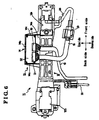
- the harness 28 extending from the grip 20 is, as shown in Fig.6, connected to the signaling circuit 52 trough a pair of connector 29, harness 18 (a connecting member), and a connector 17. That is, in the door handle 10, the signaling circuit 52, which is electrically connected to the primary transmitting antenna 54, the sensor electrode 51, and the lock switch 26 provided on the grip 20, and the main frame 12 are integrally provided.
- the signaling circuit 52 is connected to harness 19 through a connector 18, and the harness 19 is connected to a board (not shown) provided within the door lock device 62 through an opening (not shown) formed on a housing of the door lock device 62.
- the board of the door lock device 62 is connected to the controller 60 provided on the vehicle trough another harness (not shown).
- the signaling circuit 52 and the main frame 12 are integrally provided.
- the harness 28 and the harness 16 for connection between the signaling circuit 52 and the primary transmitting antenna 54 may have length being capable of connecting between the grip 20 and the main frame 12. That Is, the connection can be simplified, and generation of noise can be prevented.
- the primary transmitting antenna 54 of the door handle 10 is electrically connected to the controller 60 through the door lock device 62. That is, the harness between the door lock device 62 and the controller 60 and the harness between the primary transmitting antenna 54 of the door handle 10 and the controller 60 are unified, then wiring structure can be simplified. Especially, since various members such as a window glass 40 (shown in Fig. 4 and Fig.5) are provided in the vehicle door 30, the simplification of the wiring structure is very effective.
- the harness 16 and the harness 19 extend through the lower opening portion 13a opening downward. That is, if the chassis 13 is watered from above, water is difficult to enter in the chassis 13 through the lower opening portion 13a, and then the chassis 13 has the good water proofing property concerning the signaling circuit 52 provided within the chassis 13.
- the harness 16 and the harness 19 are provided along the base wall portion 14a integrally extending from the main frame 12. That is, the harness 16 and the harness 19 are separated from the members (the window glass 40) in the vehicle door 30 by the base wall portion 14a, and then the base wall portion 14a functions as a protector for preventing the harness 16 and the harness 19 from interfering with the window glass 40.
- the upper side of base wall portion 14a is aslant outside, as described above. That is, clearance between the upper side of the base wall portion 14a and the members (the window glass 40), which are located inside at a distance from the base wall portion 14a, can be sufficiently ensured.
- the chassis 13 for protecting the signaling circuit 52 Is integrally formed with the main frame 12.
- a protector for protecting the signaling circuit 52 does not need to be provided, the number of components can be reduced, and then the door handle 10 can be simplified.
- the chassis 13 since the connected portion 14e between the upper wall portion 14b and the cover portion 15 has the labyrinthine structure, if the chassis 13 is watered from above, water is difficult to enter In the chassis 13 through the connected portion 14e. That is, the chassis 13 has the good water proofing property concerning the signaling circuit 52 provided within the chassis 13.
- the upper wall portion 14b extending from the base wall portion 14a further extends outside beyond the position of the connected portion 14e, if the chassis 13 Is watered from above, water is difficult to enter in the chassis 13 through the connected portion 14e. That is, the good water proofing property concerning the signaling circuit 52 can be attained.
Landscapes
- Lock And Its Accessories (AREA)
Abstract
Description
- This invention generally relates to a door handle device. More particularly, this invention pertains to a door handle device applied to a vehicle door.
- For example, a known door handle device is disclosed in a Japanese Patent Laid-open Publication No. 2002-30844. This door handle device includes a handle frame and a handle grip. The handle frame is fixed to an outer panel of a vehicle door. The handle grip is provided on the handle frame from the outside of a vehicle through the outer panel, and electrical components are included in the handle grip.
- In the door handle device, the handle grip includes an antenna as one of the electrical components. The antenna transmits an identification signal with predetermined frequency to the outside of the vehicle. An oscillating circuit for keeping the antenna oscillating is provided between an inner panel of the vehicle door and a door trim through harness. In this case, since a window glass is located in the vehicle door, the harness connecting the antenna to the oscillating circuit has to be provided so as not to interfere with the window glass. Thus, wiring structure between the antenna and the oscillating circuit cannot be simplified, and noise may be generated due to the complicated wiring structure.
- The present invention therefore seeks to provide a door handle device in which wiring structure between electric components provided within a door handle and a circuit connected to the electric components is simplified.
- According to an aspect of the present invention, a door handle device includes a frame fixed to the inside of an outer panel of a vehicle door and a grip provided on the frame from the outside of a vehicle and including an electrical component. The frame is integrally provided with a circuit electrically connected to the electrical component.
- According to another aspect of the present invention, the door handle device further includes a chassis integrally formed with the frame, and the circuit is provided within the chassis.
- The foregoing and additional features and characteristics of the present invention will become more apparent from the following detailed description considered with reference to the accompanying drawing figures wherein:
- Fig.1 shows a configuration of a smart entry system including a door handle device according to the present invention;
- Fig.2 shows a configuration of a smart entry system including a door handle device according to the present invention;
- Fig.3 is a perspective view of a vehicle door to which a door handle device according to the present invention is mounted;
- Fig.4 is a cross sectional view taken along the line A-A of Fig.3;
- Fig.5 is a cross sectional view taken along the line B-B of Fig.4;
- Fig.6 is a plane view of a frame of the door handle device according to the present invention;
- Fig.7 is a plane view of the frame on which a cover portion is provided; and
- Fig.8 is a cross sectional view taken along the line C-C of Fig.5.
- Hereinafter, an embodiment of the present invention is described with reference to Figs.1-8. In this embodiment, a door handle device 10 according to the present Invention is applied to a smart entry system 50 (hereinafter referred to as a system 50). The
system 50 is a door locking / unlocking system in which a vehicle door being in a locked state is switched to an unlocked state when an owner of a vehicle (hereinafter referred to as a user) is close to the vehicle and a hand of the user approaching the door handle device 10 is detected. - First, the
system 50 is briefly explained with reference to Fig.1 and Fig.2. Thesystem 50 includes an primary transmitting antenna 54 (an electrical component) communicating with the outside of the vehicle and an secondary transmittingantenna 58 communicating with the inside of the vehicle. Theprimary transmitting antenna 54 is provided within the door handle device 10 (shown in Fig.3) mounted to a vehicle door 30 (shown in Fig.3), and thesecondary transmitting antenna 56 is provided within an instrument panel in a vehicle compartment. Theprimary transmitting antenna 54 is connected to a primary transmitting portion 55, and the secondary transmittingantenna 56 is connected to a secondary transmittingportion 57. The primary transmitting portion 55 and the secondary transmittingportion 57 are connected to acontroller 60. - In the door handle device 10, a sensor electrode 51 (an electrical component) is provided. The
sensor electrode 51 detects the user approaching thevehicle door 30 based on variation of capacitance and connected to asensor detection portion 53. Thesensor detection portion 53 detects the user based on information from thesensor electrode 51 and connected to the controller 80. In this embodiment, thesensor detection portion 53 and the primary transmitting portion 55 are integrally included in a single unit as a signaling circuit 52 (a circuit), and yet can be separatedly provided. Explanation concerning thesignaling circuit 52 will be provided later. - The
controller 60 respectively transmits a primary request signal (hereinafter referred to as an outside request signal) and a secondary request signal (hereinafter referred to as an inside request signal) to the primary transmitting portion 55 and thesecondary transmitting portion 57. In this embodiment, bothantennae - The vehicle is provided with a
receiving antenna 58, and an identification signal outputted from the portable device 70 is received by thereceiving antenna 58. In this embodiment, the identification signal has frequency of 300MHz. This identification signal is demodulated at a receivingportion 59 and then inputted to thecontroller 60. - The
controller 60 is connected to a door lock device 62 provided on thevehicle door 30. In the door lock device 62, switching between a locked state and an unlocked state Is performed by thecontroller 60. As regarding various switches and sensors connected to the controller 60 (for example, a courtesy switch which detects whether thevehicle door 30 is opened or closed to the vehicle), detailed explanation is omitted. - Fig.2 shows a system configuration of the portable device 70 applied to the
system 50. The portable device 70 includes a transmittingantenna 74 and a receivingantenna 75. The transmittingantenna 74 transmits the identification signal with frequency of 300MHz to the vehicle. Thereceiving antenna 75 receives the outsider inside request signals with frequency of 134kHz transmitted from the vehicle. The transmittingantenna 74 and thereceiving antenna 75 are connected to a transceivingcircuit 73. Thetransceiving circuit 73 is connected to a controller 71. - The request signal from the vehicle received by the
receiving antenna 75 is inputted to the controller 71 trough thetransceiving circuit 73. The controller 71 transmits a response signal, which includes an identification code having been memorized in amemory 72, to the transceivingcircuit 73 responding to the request signal. The response signal is modulated at thetransceiving circuit 73 and then transmitted to the vehicle with frequency of 300MHz from the transmittingantenna 74. - Next, operation of the
system 50 is explained below. When the door lock device 82 of thevehicle door 30 is In the locked state, If the user exists within a predetermined distance from the vehicle, the outside request signal transmitted from theprimary transmitting antenna 54 can be transmitted to the receivingantenna 74 of the portable device 70 of the user. In the portable device 70, as described above, the controller 71 transmits the response signal responding to the outside request signal. - When the response signal transmitted from the transmitting
antenna 74 of the portable device 70 is received by the receivingantenna 58 of the vehicle, the identification code demodulated by the receivingportion 59 is checked against an identification code having been memorized in a memory 61 by thecontroller 60. After the check between the identification codes is approved, thecontroller 60 is in an unlock standby state. - When the hand of the user approaches the door handle 10, variation of capacitance is generated between the
sensor electrode 51 and thesensor detection portion 53. After the hand of the user approaching thesensor electrode 51 Is detected based on the variation of capacitance, a detection signal Is transmitted to thecontroller 60 from thesensor detection portion 53. Responding to the detection signal, thecontroller 60 transmits a switching signal for switching to the unlocked state to the door lock device 62. Then, an actuator (not shown) in the door lock device 62 is operated, and the locked state is switched to the unlocked state in the door lock device 62. - Next, with reference to Figs.3-8, structure of the door handle 10 applied to the
system 50 is specifically explained. Fig.3 shows a perspective view of thevehicle door 30 to which the door handle 10 is mounted. Thevehicle door 30 is a swing-type vehicle door at a driver's seat. In Fig.3, an outer panel of thevehicle door 30 Is omitted for the purpose of simplification. - The door handle 10 mainly includes a
frame 11 and agrip 12. As shown in Fig.4, theframe 11 is fixed to the inside of anouter panel 31 of thevehicle door 30 by using twoscrews 32. Theframe 11 is resinous and integrally includes amain frame 12 and achassis 13, as shown in Figs.3-8 In detail. - As shown in Fig.4, the
main frame 12 extends In directions of the front and back side of the vehicle (a longitudinal direction of the vehicle), and the outside of themain frame 12 has a curved shape. This curved shape of themain frame 12 corresponds to a curved shape formed on theouter panel 31. As shown in Fig.6 and Fig.7, themain frame 12 includes openingportions opening portion 12a, anarm 21 a of a grip 20 (say later) is inserted, In theopening portion 12b, ahandle lever 21 b of the grip 20 (say later) and acylinder case portion 24 of akey cylinder 24 fixed to a cap 23 (say later) are Inserted. - Next, structure of the
chassis 13 is explained. As shown in Figs.5-8, thechassis 13 mainly includes acase portion 14 and acover portion 15. Thecase portion 14 further includes abase wall portion 14a, anupper wall portion 14b, and twolateral wall portions 14c. Thebase wall portion 14a is formed at an approximately middle part of themain frame 12 so as to have predetermined width along the longitudinal direction of the vehicle and to extend integrally upward from themain frame 12. As shown in Fig.5, thebase wall portion 14a has a bended-shaped cross section, and an upper side of thebase wall portion 14a is aslant outside (at an angle of α degrees to a perpendicular line). Theupper wall portion 14b Is formed so as to extend outside from an upper end of thebase wall portion 14a. As shown in Fig.8, eachlateral wall portion 14c is formed so as to extend outside from both lateral ends of thebase wall portion 14a. As explained above, thecase portion 14 includes anouter opening portion 14d opening outside. - As shown in Fig.5, the
cover portion 15 is fixed to thecase portion 14 so that theouter opening 14d of thecase portion 14 can be covered. An upper side of thecover portion 15 Is aslant outside so as to be parallel with the upper side of thebase wall portion 14a, and an upper end 15a of thecover portion 15 is connected to theupper wall portion 14b. A connected portion 14e between the upper end 15a and theupper wall portion 14b has what we call a labyrinthine structure in which the upper end 15a is held between a pair of flanges formed so as to extend downward from theupper wall portion 14b. Further, theupper wall portion 14b extends outside beyond a position of the connected portion 14e. According to the labyrinthine structure and theupper wall portion 14b extending beyond the connected portion 14e, if thechassis 13 is watered from above, water is difficult to enter in thechassis 13. Thus, thechassis 13 has a good water proofing property concerning thesignaling circuit 52 provided within thechassis 13. In addition, as shown in Fig.8, eachlateral wall portion 14c is connected to both lateral ends of thecover portion 15 so that eachlateral wall 14c can be held between a pair of flanges formed on thecover portion 15. That is, thelateral wall portions 14c are connected to thecover portion 15 by means of the labyrinthine structure in common with the connected portion 14e. - As shown in Fig.5 and Fig.7. a lower side of the
cover portion 15 extends so as to face themain frame 12. Thecover portion 15 is located outside at a predetermined distance from themain frame 12, and thechassis 13 includes a lower opening portion 13a opening downward. - Next, explanation concerning the
grip 20 is provided. As shown in Fig.4 and Fig.5, thegrip 20 includes abase 21 and acover 22 made from metal or resin. Thecover 22 is fixed to thebase 21 by using twoscrews 25, and a space is provided within thegrip 20. Thearm 21 a and thehandle lover 21 b are formed at the front and back side of thegrip 20 respectively. Thegrip 20 is assembled to themain frame 12 by inserting thehandle lever 21 b in theopening portion 12b after thearm 21a is inserted in a receivingspace 12c through theopening portion 12a of themain frame 12. Then, thegrip 20 is fixed to theouter panel 31 of thevehicle door 30. In thegrip 20 assembled to theouter panel 31, thehandle lever 21 b is connected to a cable 33 (shown in Fig.6) through a crank mechanism (not shown). Thecable 33 is connected to an outside opening lever (not shown) operating the door lock device 62. Thus, when thegrip 20 is operated so as to be pivoted about thearm 21a on thevehicle door 30, the outside opening lever of the door lock device 62 is operated. Then a latch mechanism (not shown) is operated, and thevehicle door 30 is opened. - As shown in Fig.4, the
cap 23 Is fixed to thevehicle door 30 at the back side relative to thegrip 20. Thecap 23 is formed so that outer design of thecap 23 can be identical with that of thegrip 20, and thekey cylinder 24 and thecylinder case 24a are provided within thecap 23. Thecylinder case 24a is directly connected to the door lock device 62 trough theopening portion 12b of themain frame 12, and then operation of thekey cylinder 24 Is transmitted to the door lock device 62. - As shown in Fig.4, the
primary transmitting antenna 54, thesensor electrode 51, and alock switch 26 are provided within the space of thegrip 20. Theprimary transmitting antenna 54 is made of a ferrite core where wire is coiled so as to be biaxial and functions as a biaxial antenna. Thesensor electrode 51 extends in the longitudinal direction of the vehicle and made of nonmagnetic and conductive materials such as copper and brass. Thesensor electrode 51 is provided along thebase 21 within the space of thegrip 20, and then the hand of the user approaching a space between thegrip 20 and theouter panel 31 can be easily detected. Thelock switch 26 is membrane switch pushed by a lock switch button 27 provided on thecover 22 of thegrip 20. When the user is close to the vehicle, the unlocked state is switched to the locked state In the door lock device 62 by thecontroller 60 if thelock switch 26 is pushed. - The
primary transmitting antenna 54, thesensor electrode 51, and thelock switch 26 are connected to harness 28 (a connecting member). Theharness 28 extends within thevehicle door 30 through an opening provided on thebase 21. - As shown In Fig.5, Fig.6, and Fig.8, a board of the
signaling circuit 52 is provided within thechassis 13. Thesignaling circuit 52 is fixed to ribs formed on thecase wall portion 14 by welding. Theharness 28 extending from thegrip 20 is, as shown in Fig.6, connected to thesignaling circuit 52 trough a pair ofconnector 29, harness 18 (a connecting member), and aconnector 17. That is, in the door handle 10, thesignaling circuit 52, which is electrically connected to theprimary transmitting antenna 54, thesensor electrode 51, and thelock switch 26 provided on thegrip 20, and themain frame 12 are integrally provided. Further, thesignaling circuit 52 is connected to harness 19 through aconnector 18, and theharness 19 is connected to a board (not shown) provided within the door lock device 62 through an opening (not shown) formed on a housing of the door lock device 62. The board of the door lock device 62 is connected to thecontroller 60 provided on the vehicle trough another harness (not shown). - As explained above, In the door handle 10, the
signaling circuit 52 and themain frame 12 are integrally provided. Thus, theharness 28 and theharness 16 for connection between the signalingcircuit 52 and theprimary transmitting antenna 54 may have length being capable of connecting between thegrip 20 and themain frame 12. That Is, the connection can be simplified, and generation of noise can be prevented. - In this embodiment, as described above, the
primary transmitting antenna 54 of the door handle 10 is electrically connected to thecontroller 60 through the door lock device 62. That is, the harness between the door lock device 62 and thecontroller 60 and the harness between theprimary transmitting antenna 54 of the door handle 10 and thecontroller 60 are unified, then wiring structure can be simplified. Especially, since various members such as a window glass 40 (shown in Fig. 4 and Fig.5) are provided in thevehicle door 30, the simplification of the wiring structure is very effective. - Further in the
chassis 13 of the door handle 10, theharness 16 and theharness 19 extend through the lower opening portion 13a opening downward. That is, if thechassis 13 is watered from above, water is difficult to enter in thechassis 13 through the lower opening portion 13a, and then thechassis 13 has the good water proofing property concerning thesignaling circuit 52 provided within thechassis 13. - Further, as shown in Fig.5, in the door handle 10 according to the embodiment, the
harness 16 and theharness 19 are provided along thebase wall portion 14a integrally extending from themain frame 12. That is, theharness 16 and theharness 19 are separated from the members (the window glass 40) in thevehicle door 30 by thebase wall portion 14a, and then thebase wall portion 14a functions as a protector for preventing theharness 16 and theharness 19 from interfering with thewindow glass 40. - Furthermore, in the door handle 10 according to the embodiment, the upper side of
base wall portion 14a is aslant outside, as described above. That is, clearance between the upper side of thebase wall portion 14a and the members (the window glass 40), which are located inside at a distance from thebase wall portion 14a, can be sufficiently ensured. - According to the present invention, the
chassis 13 for protecting thesignaling circuit 52 Is integrally formed with themain frame 12. Thus, a protector for protecting thesignaling circuit 52 does not need to be provided, the number of components can be reduced, and then the door handle 10 can be simplified. - According to the present invention, since the connected portion 14e between the
upper wall portion 14b and thecover portion 15 has the labyrinthine structure, if thechassis 13 is watered from above, water is difficult to enter In thechassis 13 through the connected portion 14e. That is, thechassis 13 has the good water proofing property concerning thesignaling circuit 52 provided within thechassis 13. - According to the present invention, since the
upper wall portion 14b extending from thebase wall portion 14a further extends outside beyond the position of the connected portion 14e, if thechassis 13 Is watered from above, water is difficult to enter in thechassis 13 through the connected portion 14e. That is, the good water proofing property concerning thesignaling circuit 52 can be attained. - The principles, preferred embodiments and mode of operation of the present invention have been described in the foregoing specification. However, the invention which is intended to be protected is not to be construed as limited to the particular embodiments disclosed. Further, the embodiments described herein is to be regarded as illustrative rather than restrictive. Variations and changes may be made by others, and equivalents employed, without departing from the spirit of the present invention. Accordingly, it is expressly intended that all such variations, changes and equivalents which fall within the spirit and scope of the present invention as defined in the claims, be embraced thereby.
Claims (7)
- A door handle device, comprising:a frame fixed to the inside of an outer panel of a vehicle door; anda grip provided on the frame from the outside of a vehicle and including an electrical component, wherein the frame is integrally provided with a circuit electrically connected to the electrical component.
- A door handle device, according to claim 1, further including a chassis integrally formed with the frame, wherein the circuit is prodded within the chassis.
- A door handle device, according to claim 2, wherein the chassis includes a lower opening portion opening downward, and a connecting member for connecting the electrical component to the circuit extends through the lower opening portion.
- A door handle device, according to claim 2 or 3, wherein the chassis includes a case portion and a cover portion, the case portion Includes a base wall portion having predetermined width along a longitudinal direction of the vehicle and extending upward from the frame and an outer opening portion opening at least outside, and the cover portion covers the outer opening portion from the outside of the vehicle.
- A door handle device, according to claim 4, wherein an upper side of the base wall portion is aslant outside.
- A door handle device, according to claim 3, 4 or 5, wherein the chassis includes an upper wall portion integrate extending outside from the upper side of the base wall portion, and an connected portion between the upper wall portion and the cover portion has labyrinthine structure.
- A door handle device, according to claim 6, wherein the upper wall portion extends outside beyond the connected portion.
Applications Claiming Priority (2)
| Application Number | Priority Date | Filing Date | Title |
|---|---|---|---|
| JP2002284172 | 2002-09-27 | ||
| JP2002284172A JP4161664B2 (en) | 2002-09-27 | 2002-09-27 | Vehicle door handle device |
Publications (1)
| Publication Number | Publication Date |
|---|---|
| EP1403456A1 true EP1403456A1 (en) | 2004-03-31 |
Family
ID=31973367
Family Applications (1)
| Application Number | Title | Priority Date | Filing Date |
|---|---|---|---|
| EP20030256069 Withdrawn EP1403456A1 (en) | 2002-09-27 | 2003-09-26 | Door handle device |
Country Status (4)
| Country | Link |
|---|---|
| US (1) | US7210715B2 (en) |
| EP (1) | EP1403456A1 (en) |
| JP (1) | JP4161664B2 (en) |
| CN (1) | CN1305710C (en) |
Cited By (2)
| Publication number | Priority date | Publication date | Assignee | Title |
|---|---|---|---|---|
| FR2919325A1 (en) * | 2007-07-23 | 2009-01-30 | Peugeot Citroen Automobiles Sa | Remote control device for bonnet of motor vehicle, has support plate ensuring fixation and/or maintenance functions of electrical wires and trim situated in environment of vertical front post, where wires are fixed on plate by collar |
| EP2076644B1 (en) * | 2006-10-09 | 2017-12-13 | Huf Hülsbeck & Fürst GmbH & Co. KG | Actuator |
Families Citing this family (43)
| Publication number | Priority date | Publication date | Assignee | Title |
|---|---|---|---|---|
| DE10336335B4 (en) * | 2003-08-08 | 2015-03-12 | Huf Hülsbeck & Fürst Gmbh & Co. Kg | Locking device for vehicles |
| US6908140B1 (en) * | 2004-02-24 | 2005-06-21 | Arvinmeritor Technology, Llc | Door module cable holder |
| DE102004019571B4 (en) * | 2004-04-22 | 2006-02-23 | Huf Hülsbeck & Fürst Gmbh & Co. Kg | Device for actuating an electrical or mechanical closing device on a door and / or a flap of a vehicle |
| EP1759929A4 (en) * | 2004-05-31 | 2010-04-21 | Furukawa Electric Co Ltd | Power supply system for vehicle |
| US7827836B2 (en) * | 2004-08-10 | 2010-11-09 | Magna Closures Inc. | Power release double-locking latch |
| JP2006242882A (en) * | 2005-03-07 | 2006-09-14 | Omron Corp | Capacitance sensor and flap handle with capacitance sensor |
| DE102005012419B4 (en) * | 2005-03-11 | 2020-09-10 | Volkswagen Ag | Bearing bracket of an outside handle of a vehicle door for motor vehicles |
| JP4645324B2 (en) * | 2005-06-29 | 2011-03-09 | 三菱自動車工業株式会社 | Vehicle door |
| DE102005031441A1 (en) * | 2005-07-04 | 2007-01-11 | Huf Hülsbeck & Fürst Gmbh & Co. Kg | handle device |
| US7504943B2 (en) | 2005-07-27 | 2009-03-17 | Aisin Seiki Kabushiki Kaisha | Object detecting apparatus |
| DE602007000993D1 (en) * | 2006-03-16 | 2009-06-10 | Aisin Seiki | Door handle device for vehicles |
| EP2118410A2 (en) * | 2007-03-05 | 2009-11-18 | Kaba AG | Access control system, and closing mechanism |
| WO2008137634A1 (en) | 2007-05-03 | 2008-11-13 | Donnelly Corporation | Illumination module for a vehicle |
| US7766401B2 (en) * | 2007-05-08 | 2010-08-03 | Gm Global Technology Operations, Inc. | Rod set clip for vehicle door |
| US7375299B1 (en) * | 2007-07-23 | 2008-05-20 | Key Plastics, Llc | Door handle |
| JP4751861B2 (en) * | 2007-07-27 | 2011-08-17 | アイシン精機株式会社 | Door handle device |
| JP4751860B2 (en) * | 2007-07-27 | 2011-08-17 | アイシン精機株式会社 | Door handle device |
| JP4938580B2 (en) * | 2007-07-27 | 2012-05-23 | アイシン精機株式会社 | Door handle device |
| US8122654B2 (en) * | 2008-03-14 | 2012-02-28 | C.R. Laurence Company, Inc. | Taper lock system |
| JP2009228293A (en) * | 2008-03-21 | 2009-10-08 | Alpha Corp | Structure of mounting part of lock control device |
| TWM350365U (en) * | 2008-05-30 | 2009-02-11 | Pi-Lin Jiang | Swimming goggle |
| US20100007463A1 (en) * | 2008-07-09 | 2010-01-14 | Magna Mirrors Of America, Inc. | Vehicle handle with control circuitry |
| JP4653825B2 (en) * | 2008-08-04 | 2011-03-16 | 本田技研工業株式会社 | Mounting structure of door inner handle device for vehicle |
| US20100088855A1 (en) * | 2008-10-14 | 2010-04-15 | Magna Mirrors Of America, Inc. | Vehicle door handle assembly |
| JP2010216176A (en) * | 2009-03-18 | 2010-09-30 | Aisin Seiki Co Ltd | Door handle device for vehicle |
| US8786401B2 (en) | 2009-12-23 | 2014-07-22 | Magna Mirrors Of America, Inc. | Extendable flush door handle for vehicle |
| US8764256B2 (en) | 2010-10-01 | 2014-07-01 | Magna Mirrors Of America, Inc. | Vehicle exterior mirror system with light module |
| US10576896B2 (en) | 2010-10-01 | 2020-03-03 | Magna Mirrors Of America, Inc. | Vehicle exterior mirror system with light module |
| JP5692532B2 (en) * | 2012-02-21 | 2015-04-01 | アイシン精機株式会社 | Opening and closing body control device for vehicle |
| JP5994151B2 (en) * | 2012-05-17 | 2016-09-21 | 株式会社ユーシン | Counterweight mounting structure for door lock device |
| JP5974767B2 (en) * | 2012-09-21 | 2016-08-23 | アイシン精機株式会社 | Door lock control system |
| DE102013207495B4 (en) * | 2013-04-25 | 2026-01-29 | Continental Automotive Technologies GmbH | Handle for a movable part of a motor vehicle and method for transferring data in a motor vehicle |
| DE102013222465A1 (en) | 2013-11-06 | 2015-05-07 | Volkswagen Aktiengesellschaft | Locking device for a door or flap |
| WO2016069310A1 (en) * | 2014-10-29 | 2016-05-06 | Adac Plastics, Inc. | Decoupled handle switch |
| DE102016103428A1 (en) * | 2016-02-26 | 2017-08-31 | Kiekert Ag | Motor vehicle lock |
| DE102017008340A1 (en) * | 2017-09-05 | 2019-03-07 | Huf Hülsbeck & Fürst Gmbh & Co. Kg | Motor vehicle door handle assembly with embedded electronics |
| FR3081179B1 (en) * | 2018-05-18 | 2020-07-10 | U-Shin Italia S.P.A. | AUTOMOTIVE DOOR HANDLE DEVICE WITH OPTIMIZED CONNECTIONS |
| FR3081487B1 (en) * | 2018-05-28 | 2020-05-01 | Continental Automotive France | DEVICE FOR DETECTION BY INDUCTION OF INTENT OF LOCKING OF A MOTOR VEHICLE OPENING ELEMENT WITH TARGET ON A LEVER ARM |
| DE102019135038A1 (en) | 2018-12-19 | 2020-06-25 | Magna Closures Inc. | EXTENDABLE HANDLE SYSTEM WITH REMOTE CONTROLLED ACTUATOR CROSS REFERENCE TO RELATED APPLICATION |
| JP7432401B2 (en) * | 2020-03-11 | 2024-02-16 | トヨタ紡織株式会社 | Vehicle interior materials |
| DE202020103981U1 (en) * | 2020-07-09 | 2020-08-11 | D. la Porte Söhne GmbH | Remotely actuated release device for a vehicle door lock |
| DE102020125097A1 (en) * | 2020-09-25 | 2022-03-31 | Huf Hülsbeck & Fürst Gmbh & Co. Kg | Door handle assembly for a motor vehicle |
| DE102023201129A1 (en) * | 2023-02-10 | 2024-08-14 | Witte Automotive Gmbh | Electronic sensor module and handle module |
Citations (5)
| Publication number | Priority date | Publication date | Assignee | Title |
|---|---|---|---|---|
| FR2772818A1 (en) * | 1997-12-23 | 1999-06-25 | Valeo Securite Habitacle | Car security opening system |
| EP0999324A2 (en) * | 1998-11-03 | 2000-05-10 | Valeo Sicurezza Abitacolo S.p.A. | Vehicle door handle |
| FR2802562A1 (en) * | 1999-12-21 | 2001-06-22 | Valeo Securite Habitacle | Door handle for car has a maneuver plate with a lug cooperating with an indexing notch of the support when the plate is in a non-operating position |
| DE10043289A1 (en) * | 2000-09-02 | 2002-03-28 | Valeo Gmbh & Co Schliessyst Kg | U-shaped mounting for vehicle door with outer handle and lock, provides for door handle support, window passage, lock and electrical connections in modular assembly |
| FR2820448A1 (en) * | 2001-02-08 | 2002-08-09 | Coutier Moulage Gen Ind | Automobile door handle has opening sensor, and dialogue unit which sends out badge search signal and receives an identification request signal |
Family Cites Families (16)
| Publication number | Priority date | Publication date | Assignee | Title |
|---|---|---|---|---|
| DE19516316C2 (en) * | 1995-05-04 | 1998-11-26 | Kiekert Ag | Safety device on a motor vehicle, which only allows a person authorized to open the motor vehicle to open the motor vehicle |
| DE19617038C2 (en) * | 1996-04-27 | 2000-11-30 | Huf Huelsbeck & Fuerst Gmbh | Locking system, in particular for motor vehicles |
| EP0808977B1 (en) * | 1996-05-21 | 2000-08-16 | Robert Bosch Gmbh | Method for controlling an electrically actuated vehicle door lock |
| FR2750155B1 (en) * | 1996-06-25 | 1998-09-04 | Valeo Securite Habitacle | DEVICE FOR CONTROLLING THE OPENING OF A LOCK OF A MOTOR VEHICLE OPENING ELEMENT |
| DE19750023A1 (en) * | 1997-11-12 | 1999-05-27 | Bosch Gmbh Robert | Device for locking and unlocking a door lock |
| FR2781247B1 (en) * | 1998-07-17 | 2000-08-18 | Valeo Securite Habitacle | SECURITY SYSTEM FOR A MOTOR VEHICLE OPENING ELEMENT HAVING A PROTECTIVE COVER |
| DE19832516A1 (en) * | 1998-07-20 | 2000-01-27 | Schulte Schlagbaum Ag | Lock, especially for a locking system |
| US6325429B1 (en) * | 1998-10-23 | 2001-12-04 | Randall C. Oxley | Electrically operated door lock |
| IT1305154B1 (en) * | 1998-11-03 | 2001-04-10 | Valeo Sicurezza Abitacolo Spa | HANDLE FOR A VEHICLE DOOR. |
| DE19856902C2 (en) * | 1998-12-10 | 2001-02-08 | Huf Huelsbeck & Fuerst Gmbh | External door handle, especially for vehicles, with a handle and with a pressure actuator integrated into it |
| FR2789433B1 (en) * | 1999-02-05 | 2001-04-13 | Valeo Securite Habitacle | SECURITY SYSTEM FOR A MOTOR VEHICLE OPENING ELEMENT |
| JP3714129B2 (en) | 2000-07-14 | 2005-11-09 | アイシン精機株式会社 | Door opener |
| JP2002057564A (en) * | 2000-08-11 | 2002-02-22 | Aisin Seiki Co Ltd | Human body detector |
| JP3614789B2 (en) * | 2001-03-28 | 2005-01-26 | 株式会社ホンダロック | Vehicle out-handle device |
| JP3515083B2 (en) * | 2001-04-23 | 2004-04-05 | タキゲン製造株式会社 | Lock handle device for drawer rotating door |
| JP3566943B2 (en) * | 2001-07-02 | 2004-09-15 | アイシン精機株式会社 | Vehicle door handle |
-
2002
- 2002-09-27 JP JP2002284172A patent/JP4161664B2/en not_active Expired - Fee Related
-
2003
- 2003-09-26 EP EP20030256069 patent/EP1403456A1/en not_active Withdrawn
- 2003-09-27 CN CNB031602045A patent/CN1305710C/en not_active Expired - Fee Related
- 2003-09-29 US US10/671,544 patent/US7210715B2/en not_active Expired - Fee Related
Patent Citations (5)
| Publication number | Priority date | Publication date | Assignee | Title |
|---|---|---|---|---|
| FR2772818A1 (en) * | 1997-12-23 | 1999-06-25 | Valeo Securite Habitacle | Car security opening system |
| EP0999324A2 (en) * | 1998-11-03 | 2000-05-10 | Valeo Sicurezza Abitacolo S.p.A. | Vehicle door handle |
| FR2802562A1 (en) * | 1999-12-21 | 2001-06-22 | Valeo Securite Habitacle | Door handle for car has a maneuver plate with a lug cooperating with an indexing notch of the support when the plate is in a non-operating position |
| DE10043289A1 (en) * | 2000-09-02 | 2002-03-28 | Valeo Gmbh & Co Schliessyst Kg | U-shaped mounting for vehicle door with outer handle and lock, provides for door handle support, window passage, lock and electrical connections in modular assembly |
| FR2820448A1 (en) * | 2001-02-08 | 2002-08-09 | Coutier Moulage Gen Ind | Automobile door handle has opening sensor, and dialogue unit which sends out badge search signal and receives an identification request signal |
Cited By (2)
| Publication number | Priority date | Publication date | Assignee | Title |
|---|---|---|---|---|
| EP2076644B1 (en) * | 2006-10-09 | 2017-12-13 | Huf Hülsbeck & Fürst GmbH & Co. KG | Actuator |
| FR2919325A1 (en) * | 2007-07-23 | 2009-01-30 | Peugeot Citroen Automobiles Sa | Remote control device for bonnet of motor vehicle, has support plate ensuring fixation and/or maintenance functions of electrical wires and trim situated in environment of vertical front post, where wires are fixed on plate by collar |
Also Published As
| Publication number | Publication date |
|---|---|
| US7210715B2 (en) | 2007-05-01 |
| JP2004116236A (en) | 2004-04-15 |
| CN1496898A (en) | 2004-05-19 |
| CN1305710C (en) | 2007-03-21 |
| JP4161664B2 (en) | 2008-10-08 |
| US20040125545A1 (en) | 2004-07-01 |
Similar Documents
| Publication | Publication Date | Title |
|---|---|---|
| US7210715B2 (en) | Door handle device | |
| EP2003621B1 (en) | Door handle for vehicle and smart entry system for vehicle using the same | |
| US7984937B2 (en) | Door handle apparatus for a vehicle | |
| JP3696866B2 (en) | Door opener | |
| JP3566943B2 (en) | Vehicle door handle | |
| US6002341A (en) | Door lock control apparatus for a vehicle | |
| JP4655230B2 (en) | Bobbin for bar antenna, bar antenna and vehicle door handle | |
| JP3714129B2 (en) | Door opener | |
| JP2010216176A (en) | Door handle device for vehicle | |
| EP1574385B1 (en) | Passive entry system | |
| EP1384844A2 (en) | Door handle for a vehicle | |
| US6400040B1 (en) | Vehicle ignition and remote keyless entry assembly | |
| JP4211471B2 (en) | Waterproof switch structure | |
| JP3826881B2 (en) | Vehicle door handle device | |
| JP3897728B2 (en) | Vehicle door handle device | |
| US20040154362A1 (en) | Vehicle door operating apparatus | |
| EP0950573B1 (en) | Lever combination switch unit | |
| JP3639292B1 (en) | Door opener | |
| EP1686652B1 (en) | Antenna device | |
| JP4321099B2 (en) | Door handle grip | |
| JP2008057199A (en) | Vehicle door handle device and manufacturing method thereof | |
| JP4067252B2 (en) | Smart entry system for vehicles | |
| JP2004162338A (en) | Vehicle door handle device | |
| JP2004060368A (en) | Door lock system | |
| KR20090120711A (en) | Vehicle door handle with touch sensor, and door unlock |
Legal Events
| Date | Code | Title | Description |
|---|---|---|---|
| PUAI | Public reference made under article 153(3) epc to a published international application that has entered the european phase |
Free format text: ORIGINAL CODE: 0009012 |
|
| AK | Designated contracting states |
Kind code of ref document: A1 Designated state(s): AT BE BG CH CY CZ DE DK EE ES FI FR GB GR HU IE IT LI LU MC NL PT RO SE SI SK TR |
|
| AX | Request for extension of the european patent |
Extension state: AL LT LV MK |
|
| 17P | Request for examination filed |
Effective date: 20040915 |
|
| AKX | Designation fees paid |
Designated state(s): DE FR GB TR |
|
| 17Q | First examination report despatched |
Effective date: 20041213 |
|
| 17Q | First examination report despatched |
Effective date: 20041213 |
|
| STAA | Information on the status of an ep patent application or granted ep patent |
Free format text: STATUS: THE APPLICATION IS DEEMED TO BE WITHDRAWN |
|
| 18D | Application deemed to be withdrawn |
Effective date: 20110401 |