EP1403197A1 - Pneumatic dispatch cartridge - Google Patents
Pneumatic dispatch cartridge Download PDFInfo
- Publication number
- EP1403197A1 EP1403197A1 EP20030103438 EP03103438A EP1403197A1 EP 1403197 A1 EP1403197 A1 EP 1403197A1 EP 20030103438 EP20030103438 EP 20030103438 EP 03103438 A EP03103438 A EP 03103438A EP 1403197 A1 EP1403197 A1 EP 1403197A1
- Authority
- EP
- European Patent Office
- Prior art keywords
- lid
- pneumatic dispatch
- cartridge according
- access opening
- cartridge
- Prior art date
- Legal status (The legal status is an assumption and is not a legal conclusion. Google has not performed a legal analysis and makes no representation as to the accuracy of the status listed.)
- Granted
Links
Images


Classifications
-
- B—PERFORMING OPERATIONS; TRANSPORTING
- B65—CONVEYING; PACKING; STORING; HANDLING THIN OR FILAMENTARY MATERIAL
- B65G—TRANSPORT OR STORAGE DEVICES, e.g. CONVEYORS FOR LOADING OR TIPPING, SHOP CONVEYOR SYSTEMS OR PNEUMATIC TUBE CONVEYORS
- B65G51/00—Conveying articles through pipes or tubes by fluid flow or pressure; Conveying articles over a flat surface, e.g. the base of a trough, by jets located in the surface
- B65G51/04—Conveying the articles in carriers having a cross-section approximating that of the pipe or tube; Tube mail systems
- B65G51/06—Despatch carriers for tube mail
Definitions
- the invention relates to a pneumatic dispatch cartridge comprising a cartridge housing with at least one access opening formed therein, which access opening can be closed by closure means.
- Pneumatic dispatch cartridges for use in a pneumatic dispatch system can be used for transporting various objects. Most common is the transportation of documents and/or small-sized goods. In other applications, however, a pneumatic dispatch cartridge can also be used for transporting flowable goods, such as liquids. Such an application is found in hospitals and laboratories, for example, where the pneumatic dispatch system can be used for despatching (blood) samples, amongst other things. It stands to reason that stringent requirements are made with regard to the closure of the access opening of the cartridge housing in the case of such an application. After all, the access opening must be prevented from opening unintentionally during transport of a pneumatic dispatch cartridge through the pneumatic dispatch system, which might lead to the contents of the pneumatic dispatch cartridge spreading over the pneumatic dispatch system.
- the present invention provides a pneumatic dispatch cartridge comprising a cartridge housing with at least one access opening formed therein, which opening can be closed by closure means, characterized in that said closure means consist of a lid which is hingedly connected to the cartridge housing at the location of a first hinge, which lid closes the access opening in a closing position thereof, as well as a clamping element, which is likewise hingedly connected to the cartridge housing at the location of a second hinge, which clamping element, in a clamping position thereof, engages the lid in the closing position thereof, wherein locking means are furthermore provided for retaining the clamping element in the clamping position thereof.
- the effectiveness of the cooperation between the lid and the clamping element can be optimised in that, in accordance with a special embodiment of the pneumatic dispatch cartridge according to the invention, the lid and the clamping element are hingedly connected to the cartridge housing at substantially diametrically opposed positions with respect to the access opening.
- the subclaims define the preferred embodiments of the pneumatic dispatch cartridge according to the invention.
- a pneumatic dispatch cartridge according to the invention is partially shown.
- the pneumatic dispatch cartridge comprises a cartridge housing 1, which is preferably made in one piece, in which housing at least one access opening 2 is formed.
- the access opening 2 is present on a frontal side of the cartridge housing 1.
- a corresponding access opening may be formed on the opposite frontal side (not shown) of the cartridge housing 1, which opening may or may not be provided with the closure means to be described in more detail hereinafter.
- a first hinge 3 is connected to the cartridge housing 1 in a manner yet to be described.
- a lid 4 is hingedly connected to the cartridge housing 1 at the location of said first hinge 3.
- the lid 4 consists of a supporting arm 5, which is connected to the cartridge housing 1 at the location of the hinge 3, and a lid member 6, which is supported by said supporting arm 5.
- the supporting arm 5 and the lid member 6 are movably interconnected, e.g. by means of an assembly consisting of a pin 17 and an elongated hole 8.
- a spring mechanism e.g. a compression spring 9 is present between the two parts.
- a flexible sealing element e.g. an O-ring 22, is present in a circumferential groove of the lid member 6, which ring can mate with the inner circumferential wall of the cartridge housing 1 for sealing the access opening 2.
- a second hinge 10 Diametrically opposite the first hinge 3 is a second hinge 10. Like the first hinge 3, the second hinge 10 is connected to the cartridge housing 1.
- a clamping element 11 is hingedly connected to the cartridge housing 1 at the location of said second hinge 10.
- said clamping element is embodied as a cover 12 in which a hold-down roller 13 is mounted, and in which a locking hook 15, which pivots about a pivot, pin 14 is present.
- the locking hook 15 is loaded by a compression spring 16, with a recess 17 formed in the cover 12 giving access to said locking hook.
- the hinges 3 and 10 may be connected to the cartridge housing 1 by means of a clamping ring 18.
- the cartridge housing 1 is to that end provided with a circular projection 19, whilst the clamping ring 18 is provided with a corresponding recess 20.
- the hinges 3 and 10 are preferably embodied as so-called multi-leaf hinges, i.e. hinges comprising a plurality of lamella-like hinge leaves arranged in side-by-side relationship.
- the pneumatic dispatch cartridge according to the present invention is used as follows.
- the lid 4 is first pivoted about the hinge 3 from the position that is shown in Fig. 1 in the direction indicated by the arrow 21.
- the lid 4 reaches a closing position, in which the O-ring position sealingly mates with the inner circumferential wall of the cartridge housing 1 for closing the access opening 2.
- the lid member 6 accommodating the O-ring 22 is adjusted in a self-locating manner by the cooperation between the pin 7 and the elongated hole 8, whilst the compression spring 9 ensures that the lid member 6 is positioned in the access opening 2.
- the clamping element 11 is pivoted about its hinge 10.
- the hold-down roller 13 will engage the upper side of the supporting arm 5 to an increasing extent, so that the lid 4 is urged into the access opening 2 with increasing force.
- a rising edge 23 of the locking hook 15 comes into contact with a sloping upper side of a locking nose 24 formed on the supporting arm 5.
- the locking hook 15 is slightly pivoted about the pivot pin 14 against the force of the compression 16, until the end of the locking hook 15 has passed the locking nose 24 and the locking hook 15 returns to its starting position under the influence of the pressure force exerted by the compression spring 16.
- the position of the hold-down roller 13 near the hinge 10 and the large distance between the hold-down roller 13 and the locking hook 15 make it possible to realise a large hold-down force of the hold-down roller 13 on the supporting arm 5 whilst using a relatively small locking force at the location of the locking hook 15 and the locking nose 24.
- the locking member 15 can be engaged via the access opening 17 in order to be pivoted in such a manner that the end of the locking hook releases the locking nose 24.
- the clamping element 11 can first be pivoted to the position that is shown in Fig. 2, after which the lid 4 can be pivoted to the position that is shown in Fig. 1.
- said pivoting of the clamping element 11 can already take place automatically under the influence of the upward movement of the supporting arm 5 engaging the hold-down roller 13, which is effected by the compression spring 9. In this way a visual indication of the fact that the pneumatic dispatch cartridge according to the invention is not correctly closed (i.e. locked) is furthermore provided.
- the pneumatic dispatch cartridge can only be closed by pivoting the lid 4 and the clamping element 11 in a specific order (first the lid, then the clamping element). The same obtains with regard to opening the cartridge.
- the cover 12 of the clamping element 11 envelopes the lid 4 practically completely and substantially adjoins the circumferential edge of the access opening 2.
- the various parts of the pneumatic dispatch cartridge consist of materials that can be sterilised.
- means for tracing or controlling the pneumatic dispatch cartridge e.g. a built-in chip
- means for indicating any leakage from the pneumatic dispatch cartridge e.g. chemically reacting indicators
Abstract
Description
- The invention relates to a pneumatic dispatch cartridge comprising a cartridge housing with at least one access opening formed therein, which access opening can be closed by closure means.
- Pneumatic dispatch cartridges for use in a pneumatic dispatch system can be used for transporting various objects. Most common is the transportation of documents and/or small-sized goods. In other applications, however, a pneumatic dispatch cartridge can also be used for transporting flowable goods, such as liquids. Such an application is found in hospitals and laboratories, for example, where the pneumatic dispatch system can be used for despatching (blood) samples, amongst other things. It stands to reason that stringent requirements are made with regard to the closure of the access opening of the cartridge housing in the case of such an application. After all, the access opening must be prevented from opening unintentionally during transport of a pneumatic dispatch cartridge through the pneumatic dispatch system, which might lead to the contents of the pneumatic dispatch cartridge spreading over the pneumatic dispatch system.
- Accordingly, it is an object of the present invention to provide an improved pneumatic dispatch cartridge of the present type, in which the closure means can guarantee a reliable closure of the access opening.
- In order to accomplish the above object, the present invention provides a pneumatic dispatch cartridge comprising a cartridge housing with at least one access opening formed therein, which opening can be closed by closure means, characterized in that said closure means consist of a lid which is hingedly connected to the cartridge housing at the location of a first hinge, which lid closes the access opening in a closing position thereof, as well as a clamping element, which is likewise hingedly connected to the cartridge housing at the location of a second hinge, which clamping element, in a clamping position thereof, engages the lid in the closing position thereof, wherein locking means are furthermore provided for retaining the clamping element in the clamping position thereof.
- The aforesaid combination of the lid and the clamping element enables a reliable closure of the access opening.
- The effectiveness of the cooperation between the lid and the clamping element can be optimised in that, in accordance with a special embodiment of the pneumatic dispatch cartridge according to the invention, the lid and the clamping element are hingedly connected to the cartridge housing at substantially diametrically opposed positions with respect to the access opening.
- The subclaims define the preferred embodiments of the pneumatic dispatch cartridge according to the invention.
- The invention will be explained in more detail hereinafter with reference to the drawing, which shows an embodiment of the pneumatic dispatch cartridge. In the drawing:
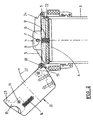
- Fig. 1 shows an embodiment of the pneumatic dispatch cartridge according to the invention in an open position thereof;
- Fig. 2 shows the pneumatic dispatch cartridge of Fig. 1 in a partially closed position thereof; and
- Fig. 3 shows the same pneumatic dispatch cartridge in a fully open position thereof.
- Before giving a detailed description of the Figures, it is noted that said Figures show the pneumatic dispatch cartridge partially in side elevation and partially in longitudinal section.
- In Fig. 1, a pneumatic dispatch cartridge according to the invention is partially shown. The pneumatic dispatch cartridge comprises a
cartridge housing 1, which is preferably made in one piece, in which housing at least oneaccess opening 2 is formed. As is usual with pneumatic dispatch cartridges of this type, theaccess opening 2 is present on a frontal side of thecartridge housing 1. A corresponding access opening may be formed on the opposite frontal side (not shown) of thecartridge housing 1, which opening may or may not be provided with the closure means to be described in more detail hereinafter. - A
first hinge 3 is connected to thecartridge housing 1 in a manner yet to be described. Alid 4 is hingedly connected to thecartridge housing 1 at the location of saidfirst hinge 3. - In the illustrated embodiment, the
lid 4 consists of a supportingarm 5, which is connected to thecartridge housing 1 at the location of thehinge 3, and alid member 6, which is supported by said supportingarm 5. The supportingarm 5 and thelid member 6 are movably interconnected, e.g. by means of an assembly consisting of apin 17 and anelongated hole 8. A spring mechanism, e.g. acompression spring 9, is present between the two parts. A flexible sealing element, e.g. an O-ring 22, is present in a circumferential groove of thelid member 6, which ring can mate with the inner circumferential wall of thecartridge housing 1 for sealing the access opening 2. - Diametrically opposite the
first hinge 3 is asecond hinge 10. Like thefirst hinge 3, thesecond hinge 10 is connected to thecartridge housing 1. Aclamping element 11 is hingedly connected to thecartridge housing 1 at the location of saidsecond hinge 10. In the illustrated embodiment, said clamping element is embodied as acover 12 in which a hold-down roller 13 is mounted, and in which alocking hook 15, which pivots about a pivot,pin 14 is present. Thelocking hook 15 is loaded by acompression spring 16, with arecess 17 formed in thecover 12 giving access to said locking hook. - The
hinges cartridge housing 1 by means of aclamping ring 18. In the illustrated embodiment thecartridge housing 1 is to that end provided with acircular projection 19, whilst theclamping ring 18 is provided with acorresponding recess 20. - In order to be able to absorb large forces, the
hinges - The pneumatic dispatch cartridge according to the present invention is used as follows. When the
access opening 2 is to be closed, thelid 4 is first pivoted about thehinge 3 from the position that is shown in Fig. 1 in the direction indicated by thearrow 21. Finally, thelid 4 reaches a closing position, in which the O-ring position sealingly mates with the inner circumferential wall of the cartridge housing 1 for closing the access opening 2. Thelid member 6 accommodating the O-ring 22 is adjusted in a self-locating manner by the cooperation between thepin 7 and theelongated hole 8, whilst thecompression spring 9 ensures that thelid member 6 is positioned in theaccess opening 2. - After the
lid 4 has thus been pivoted to the closing position as shown in Fig. 2, theclamping element 11 is pivoted about itshinge 10. The hold-down roller 13 will engage the upper side of the supportingarm 5 to an increasing extent, so that thelid 4 is urged into the access opening 2 with increasing force. Shortly before theclamping element 11 reaches the clamping position as shown in Fig. 3, a risingedge 23 of thelocking hook 15 comes into contact with a sloping upper side of a lockingnose 24 formed on the supportingarm 5. As a result, thelocking hook 15 is slightly pivoted about thepivot pin 14 against the force of thecompression 16, until the end of thelocking hook 15 has passed thelocking nose 24 and thelocking hook 15 returns to its starting position under the influence of the pressure force exerted by thecompression spring 16. - The position of the hold-down
roller 13 near thehinge 10 and the large distance between the hold-downroller 13 and thelocking hook 15 make it possible to realise a large hold-down force of the hold-downroller 13 on the supportingarm 5 whilst using a relatively small locking force at the location of thelocking hook 15 and thelocking nose 24. - The cooperation between the hold-down
roller 13 and the supportingarm 5 already starts at a point at which theclamping element 11 still includes a large angle with the access opening. This provides the following major advantage. If the locking engagement should become released within a channel of a pneumatic dispatch system, theclamping element 11 can only pivot through a small angle with respect to the access opening before coming into contact with the inner wall of the channel. In such a situation the hold-down roller 13 continues to firmly engage the supportingarm 5, however, as a result of which an effective closure of theaccess opening 2 remains ensured. Further pivoting of theclamping element 11, thereby releasing the access opening, is not possible until the cartridge has exited the channel. Conversely, the pneumatic dispatch cartridge according to the invention cannot be introduced into the channel until the access opening is effectively closed. - When the
access opening 2 is to be released, starting from the position that is shown in Fig. 3, thelocking member 15 can be engaged via the access opening 17 in order to be pivoted in such a manner that the end of the locking hook releases thelocking nose 24. Following this, theclamping element 11 can first be pivoted to the position that is shown in Fig. 2, after which thelid 4 can be pivoted to the position that is shown in Fig. 1. Once the locking element has been released, said pivoting of theclamping element 11 can already take place automatically under the influence of the upward movement of the supportingarm 5 engaging the hold-down roller 13, which is effected by thecompression spring 9. In this way a visual indication of the fact that the pneumatic dispatch cartridge according to the invention is not correctly closed (i.e. locked) is furthermore provided. - In the illustrated embodiment, the pneumatic dispatch cartridge can only be closed by pivoting the
lid 4 and theclamping element 11 in a specific order (first the lid, then the clamping element). The same obtains with regard to opening the cartridge. - In the position that is shown in Fig. 3, the
cover 12 of theclamping element 11 envelopes thelid 4 practically completely and substantially adjoins the circumferential edge of the access opening 2. - Preferably, the various parts of the pneumatic dispatch cartridge consist of materials that can be sterilised. In addition to means for tracing or controlling the pneumatic dispatch cartridge (e.g. a built-in chip), also means (e.g. a seal) that prevent unauthorized opening of the cartridge, as while as means for indicating any leakage from the pneumatic dispatch cartridge (e.g. chemically reacting indicators) may be used.
- The invention is not restricted to the embodiment as described above, which can be varied in many ways within the scope of the invention as defined in the claims.
Claims (16)
- A pneumatic dispatch cartridge comprising a cartridge housing with at least one access opening formed therein, which access opening can be closed by closure means, characterized in that said closure means consist of a lid which is hingedly connected to the cartridge housing at the location of a first hinge, which lid closes the access opening in a closing position thereof, as well as a clamping element, which is likewise hingedly connected to the cartridge housing at the location of a second hinge, which clamping element, in a clamping position thereof, engages the lid in the closing position thereof, wherein locking means are furthermore provided for retaining the clamping element in the clamping position thereof.
- A pneumatic dispatch cartridge according to claim 1, wherein said lid and said clamping element are hingedly connected to the cartridge housing at substantially diametrically opposed positions with respect to the access opening.
- A pneumatic dispatch cartridge according to claim 1 or 2, wherein the locking means consist of a locking hook formed on the clamping element, which locking hook can mate with a locking nose formed on the lid.
- A pneumatic dispatch cartridge according to claim 3, wherein said locking hook is movable against a spring load to a position in which the locking nose is released.
- A pneumatic dispatch cartridge according to claim 3 or 4, wherein said locking hook comprises a rising edge, which is to mate with the locking nose upon movement of the clamping element towards the clamping position.
- A pneumatic dispatch cartridge according to any one of the preceding claims, wherein said clamping element is provided with engaging means, such as a hold-down roller or the like, for engaging the lid.
- A pneumatic dispatch cartridge according to any one of the preceding claims, wherein said lid consists of a supporting arm, which is hingedly connected to the cartridge housing, and a lid member, which is supported by said supporting arm, for closing the access opening in the closing position thereof.
- A pneumatic dispatch cartridge according to claim 7, wherein said supporting arm and said lid member are movably interconnected.
- A pneumatic dispatch cartridge according to claim 8, wherein a spring mechanism, e.g. a compression spring or the like, is present between said supporting arm and said lid member.
- A pneumatic dispatch cartridge according to any one of the preceding claims, wherein the hinges of said lid and said clamping element are multi-leaf hinges.
- A pneumatic dispatch cartridge according to any one of the preceding claims, wherein the hinges of said lid and said clamping element are formed on a (possibly multipart) clamping ring, which can be clamped down round the cartridge housing.
- A pneumatic dispatch cartridge according to claim 11, wherein said clamping ring and said cartridge housing are provided with mating projections and recesses.
- A pneumatic dispatch cartridge according to any one of the preceding claims, wherein said lid is provided with a sealing element that mates with the circumferential edge of the access opening, e.g. an O-ring present in a circumferential groove of the lid member.
- A pneumatic dispatch cartridge according to any one of the preceding claims, wherein the clamping member is externally shaped as a cover, which envelopes the lid while adjoining the circumferential edge of the access opening in the clamping position.
- A pneumatic dispatch cartridge according to any one of the preceding claims, wherein the cartridge housing is in one piece.
- A pneumatic dispatch cartridge according to any one of the preceding claims, wherein the parts of said cartridge consist of materials that can be sterilised.
Applications Claiming Priority (2)
| Application Number | Priority Date | Filing Date | Title |
|---|---|---|---|
| NL1021538 | 2002-09-26 | ||
| NL1021538A NL1021538C2 (en) | 2002-09-26 | 2002-09-26 | Pipe post pattern. |
Publications (2)
| Publication Number | Publication Date |
|---|---|
| EP1403197A1 true EP1403197A1 (en) | 2004-03-31 |
| EP1403197B1 EP1403197B1 (en) | 2008-11-12 |
Family
ID=31973740
Family Applications (1)
| Application Number | Title | Priority Date | Filing Date |
|---|---|---|---|
| EP03103438A Expired - Lifetime EP1403197B1 (en) | 2002-09-26 | 2003-09-18 | Pneumatic dispatch cartridge |
Country Status (4)
| Country | Link |
|---|---|
| EP (1) | EP1403197B1 (en) |
| AT (1) | ATE414032T1 (en) |
| DE (1) | DE60324643D1 (en) |
| NL (1) | NL1021538C2 (en) |
Cited By (5)
| Publication number | Priority date | Publication date | Assignee | Title |
|---|---|---|---|---|
| EP1690815A2 (en) * | 2005-02-09 | 2006-08-16 | Aerocom GmbH & Co. Communicationssysteme | Pneumatic post cartridge |
| DE102007031426A1 (en) * | 2007-07-05 | 2009-01-22 | Swisslog Rohrpostsysteme Gmbh | Pneumatic tube bush, has cover held at tube socket and is formed with two-piece with inner sealing cover and outer locking element and sealing cover sealingly pressed at tube socket in closed position |
| CN101759032A (en) * | 2008-11-13 | 2010-06-30 | 北京银融科技有限责任公司 | Method for connecting cover and body of conveyer and device therefor |
| CN104261134A (en) * | 2007-05-31 | 2015-01-07 | 北京银融科技有限责任公司 | Transmitter method and device |
| JP2017107244A (en) * | 2017-03-09 | 2017-06-15 | キヤノン株式会社 | Packaging material and cartridge |
Citations (4)
| Publication number | Priority date | Publication date | Assignee | Title |
|---|---|---|---|---|
| DE890478C (en) * | 1951-05-31 | 1953-09-21 | Mix & Genest Ag | Pneumatic tube socket |
| US3073546A (en) * | 1960-12-27 | 1963-01-15 | Woodland Edward Francis | Closure for pneumatic tube carrier |
| FR1372206A (en) * | 1963-10-11 | 1964-09-11 | Int Standard Electric Corp | Improvements to pneumatic conveyors |
| DE20102433U1 (en) * | 2001-02-17 | 2001-07-26 | Aerocom Gmbh & Co Communicatio | Pneumatic tube rifle |
-
2002
- 2002-09-26 NL NL1021538A patent/NL1021538C2/en not_active IP Right Cessation
-
2003
- 2003-09-18 DE DE60324643T patent/DE60324643D1/en not_active Expired - Lifetime
- 2003-09-18 EP EP03103438A patent/EP1403197B1/en not_active Expired - Lifetime
- 2003-09-18 AT AT03103438T patent/ATE414032T1/en active
Patent Citations (4)
| Publication number | Priority date | Publication date | Assignee | Title |
|---|---|---|---|---|
| DE890478C (en) * | 1951-05-31 | 1953-09-21 | Mix & Genest Ag | Pneumatic tube socket |
| US3073546A (en) * | 1960-12-27 | 1963-01-15 | Woodland Edward Francis | Closure for pneumatic tube carrier |
| FR1372206A (en) * | 1963-10-11 | 1964-09-11 | Int Standard Electric Corp | Improvements to pneumatic conveyors |
| DE20102433U1 (en) * | 2001-02-17 | 2001-07-26 | Aerocom Gmbh & Co Communicatio | Pneumatic tube rifle |
Cited By (8)
| Publication number | Priority date | Publication date | Assignee | Title |
|---|---|---|---|---|
| EP1690815A2 (en) * | 2005-02-09 | 2006-08-16 | Aerocom GmbH & Co. Communicationssysteme | Pneumatic post cartridge |
| EP1690815A3 (en) * | 2005-02-09 | 2006-09-20 | Aerocom GmbH & Co. Communicationssysteme | Pneumatic post cartridge |
| CN104261134A (en) * | 2007-05-31 | 2015-01-07 | 北京银融科技有限责任公司 | Transmitter method and device |
| DE102007031426A1 (en) * | 2007-07-05 | 2009-01-22 | Swisslog Rohrpostsysteme Gmbh | Pneumatic tube bush, has cover held at tube socket and is formed with two-piece with inner sealing cover and outer locking element and sealing cover sealingly pressed at tube socket in closed position |
| CN101759032A (en) * | 2008-11-13 | 2010-06-30 | 北京银融科技有限责任公司 | Method for connecting cover and body of conveyer and device therefor |
| CN104787580A (en) * | 2008-11-13 | 2015-07-22 | 北京银融科技有限责任公司 | Method and device for connecting cover and body of conveyer |
| CN104787580B (en) * | 2008-11-13 | 2017-11-14 | 北京银融科技有限责任公司 | A kind of connection method and the device of transmitter lid and body |
| JP2017107244A (en) * | 2017-03-09 | 2017-06-15 | キヤノン株式会社 | Packaging material and cartridge |
Also Published As
| Publication number | Publication date |
|---|---|
| EP1403197B1 (en) | 2008-11-12 |
| ATE414032T1 (en) | 2008-11-15 |
| NL1021538C2 (en) | 2004-03-29 |
| DE60324643D1 (en) | 2008-12-24 |
Similar Documents
| Publication | Publication Date | Title |
|---|---|---|
| EP1316510B1 (en) | Hinge cap | |
| US6010029A (en) | Container lid assembly | |
| US6942117B2 (en) | Closure door system for vehicle filler neck | |
| KR101161972B1 (en) | Connector port | |
| EP1403197B1 (en) | Pneumatic dispatch cartridge | |
| KR102191470B1 (en) | Cap unit and beverage container | |
| US20170066575A1 (en) | Closure for a vessel and vessel comprising such a closure | |
| KR880010350A (en) | Photo film cartridge protective container | |
| US8695857B2 (en) | Cap and container with cap | |
| JP5332815B2 (en) | Bottle lid braking structure | |
| US6234723B1 (en) | Conveying capsule for a pneumatic tube conveyor system | |
| US6415786B1 (en) | Container for a respirator | |
| RU2344062C2 (en) | Shipping container binding ring locking device | |
| US11180297B2 (en) | Packaging for receiving a filling material | |
| US6018638A (en) | Developer container cover with rotary sealing means | |
| KR910010187B1 (en) | Lock apparatus for a door | |
| US5450844A (en) | Locking device for the container of a gas mask and breathing equipment | |
| KR200396092Y1 (en) | Safety plug and receptacle of structure | |
| US11866241B2 (en) | Container having a self-supporting cover for an outlet | |
| US20190337684A1 (en) | Packaging for receiving a filling material | |
| JP2557353Y2 (en) | Storage case for tape cassette | |
| MX2023006239A (en) | Assembly comprising a container and plugging device attached to the container. | |
| JPH09240711A (en) | Opening mechanism for lid | |
| EP1125853B1 (en) | Dispensing closure improvement | |
| JP3105890B1 (en) | Liquid container lid |
Legal Events
| Date | Code | Title | Description |
|---|---|---|---|
| PUAI | Public reference made under article 153(3) epc to a published international application that has entered the european phase |
Free format text: ORIGINAL CODE: 0009012 |
|
| AK | Designated contracting states |
Kind code of ref document: A1 Designated state(s): AT BE BG CH CY CZ DE DK EE ES FI FR GB GR HU IE IT LI LU MC NL PT RO SE SI SK TR |
|
| AX | Request for extension of the european patent |
Extension state: AL LT LV MK |
|
| 17P | Request for examination filed |
Effective date: 20040505 |
|
| AKX | Designation fees paid |
Designated state(s): AT BE BG CH CY CZ DE DK EE ES FI FR GB GR HU IE IT LI LU MC NL PT RO SE SI SK TR |
|
| 17Q | First examination report despatched |
Effective date: 20050614 |
|
| GRAP | Despatch of communication of intention to grant a patent |
Free format text: ORIGINAL CODE: EPIDOSNIGR1 |
|
| GRAS | Grant fee paid |
Free format text: ORIGINAL CODE: EPIDOSNIGR3 |
|
| GRAA | (expected) grant |
Free format text: ORIGINAL CODE: 0009210 |
|
| AK | Designated contracting states |
Kind code of ref document: B1 Designated state(s): AT BE BG CH CY CZ DE DK EE ES FI FR GB GR HU IE IT LI LU MC NL PT RO SE SI SK TR |
|
| REG | Reference to a national code |
Ref country code: GB Ref legal event code: FG4D |
|
| REG | Reference to a national code |
Ref country code: CH Ref legal event code: EP |
|
| REG | Reference to a national code |
Ref country code: IE Ref legal event code: FG4D |
|
| REF | Corresponds to: |
Ref document number: 60324643 Country of ref document: DE Date of ref document: 20081224 Kind code of ref document: P |
|
| PG25 | Lapsed in a contracting state [announced via postgrant information from national office to epo] |
Ref country code: ES Free format text: LAPSE BECAUSE OF FAILURE TO SUBMIT A TRANSLATION OF THE DESCRIPTION OR TO PAY THE FEE WITHIN THE PRESCRIBED TIME-LIMIT Effective date: 20090223 |
|
| PG25 | Lapsed in a contracting state [announced via postgrant information from national office to epo] |
Ref country code: SI Free format text: LAPSE BECAUSE OF FAILURE TO SUBMIT A TRANSLATION OF THE DESCRIPTION OR TO PAY THE FEE WITHIN THE PRESCRIBED TIME-LIMIT Effective date: 20081112 Ref country code: FI Free format text: LAPSE BECAUSE OF FAILURE TO SUBMIT A TRANSLATION OF THE DESCRIPTION OR TO PAY THE FEE WITHIN THE PRESCRIBED TIME-LIMIT Effective date: 20081112 |
|
| PG25 | Lapsed in a contracting state [announced via postgrant information from national office to epo] |
Ref country code: RO Free format text: LAPSE BECAUSE OF FAILURE TO SUBMIT A TRANSLATION OF THE DESCRIPTION OR TO PAY THE FEE WITHIN THE PRESCRIBED TIME-LIMIT Effective date: 20081112 Ref country code: BG Free format text: LAPSE BECAUSE OF FAILURE TO SUBMIT A TRANSLATION OF THE DESCRIPTION OR TO PAY THE FEE WITHIN THE PRESCRIBED TIME-LIMIT Effective date: 20090212 Ref country code: DK Free format text: LAPSE BECAUSE OF FAILURE TO SUBMIT A TRANSLATION OF THE DESCRIPTION OR TO PAY THE FEE WITHIN THE PRESCRIBED TIME-LIMIT Effective date: 20081112 Ref country code: EE Free format text: LAPSE BECAUSE OF FAILURE TO SUBMIT A TRANSLATION OF THE DESCRIPTION OR TO PAY THE FEE WITHIN THE PRESCRIBED TIME-LIMIT Effective date: 20081112 |
|
| PG25 | Lapsed in a contracting state [announced via postgrant information from national office to epo] |
Ref country code: PT Free format text: LAPSE BECAUSE OF FAILURE TO SUBMIT A TRANSLATION OF THE DESCRIPTION OR TO PAY THE FEE WITHIN THE PRESCRIBED TIME-LIMIT Effective date: 20090413 Ref country code: SE Free format text: LAPSE BECAUSE OF FAILURE TO SUBMIT A TRANSLATION OF THE DESCRIPTION OR TO PAY THE FEE WITHIN THE PRESCRIBED TIME-LIMIT Effective date: 20090212 Ref country code: CZ Free format text: LAPSE BECAUSE OF FAILURE TO SUBMIT A TRANSLATION OF THE DESCRIPTION OR TO PAY THE FEE WITHIN THE PRESCRIBED TIME-LIMIT Effective date: 20081112 |
|
| PLBE | No opposition filed within time limit |
Free format text: ORIGINAL CODE: 0009261 |
|
| STAA | Information on the status of an ep patent application or granted ep patent |
Free format text: STATUS: NO OPPOSITION FILED WITHIN TIME LIMIT |
|
| PG25 | Lapsed in a contracting state [announced via postgrant information from national office to epo] |
Ref country code: SK Free format text: LAPSE BECAUSE OF FAILURE TO SUBMIT A TRANSLATION OF THE DESCRIPTION OR TO PAY THE FEE WITHIN THE PRESCRIBED TIME-LIMIT Effective date: 20081112 |
|
| 26N | No opposition filed |
Effective date: 20090813 |
|
| PG25 | Lapsed in a contracting state [announced via postgrant information from national office to epo] |
Ref country code: MC Free format text: LAPSE BECAUSE OF NON-PAYMENT OF DUE FEES Effective date: 20090930 |
|
| REG | Reference to a national code |
Ref country code: CH Ref legal event code: PL |
|
| REG | Reference to a national code |
Ref country code: IE Ref legal event code: MM4A |
|
| PG25 | Lapsed in a contracting state [announced via postgrant information from national office to epo] |
Ref country code: IE Free format text: LAPSE BECAUSE OF NON-PAYMENT OF DUE FEES Effective date: 20090918 |
|
| PG25 | Lapsed in a contracting state [announced via postgrant information from national office to epo] |
Ref country code: LI Free format text: LAPSE BECAUSE OF NON-PAYMENT OF DUE FEES Effective date: 20090930 Ref country code: CH Free format text: LAPSE BECAUSE OF NON-PAYMENT OF DUE FEES Effective date: 20090930 Ref country code: GR Free format text: LAPSE BECAUSE OF FAILURE TO SUBMIT A TRANSLATION OF THE DESCRIPTION OR TO PAY THE FEE WITHIN THE PRESCRIBED TIME-LIMIT Effective date: 20090213 |
|
| PG25 | Lapsed in a contracting state [announced via postgrant information from national office to epo] |
Ref country code: LU Free format text: LAPSE BECAUSE OF NON-PAYMENT OF DUE FEES Effective date: 20090918 |
|
| PG25 | Lapsed in a contracting state [announced via postgrant information from national office to epo] |
Ref country code: HU Free format text: LAPSE BECAUSE OF FAILURE TO SUBMIT A TRANSLATION OF THE DESCRIPTION OR TO PAY THE FEE WITHIN THE PRESCRIBED TIME-LIMIT Effective date: 20090513 |
|
| PG25 | Lapsed in a contracting state [announced via postgrant information from national office to epo] |
Ref country code: TR Free format text: LAPSE BECAUSE OF FAILURE TO SUBMIT A TRANSLATION OF THE DESCRIPTION OR TO PAY THE FEE WITHIN THE PRESCRIBED TIME-LIMIT Effective date: 20081112 |
|
| PG25 | Lapsed in a contracting state [announced via postgrant information from national office to epo] |
Ref country code: CY Free format text: LAPSE BECAUSE OF FAILURE TO SUBMIT A TRANSLATION OF THE DESCRIPTION OR TO PAY THE FEE WITHIN THE PRESCRIBED TIME-LIMIT Effective date: 20081112 |
|
| PGFP | Annual fee paid to national office [announced via postgrant information from national office to epo] |
Ref country code: GB Payment date: 20120926 Year of fee payment: 10 |
|
| PGFP | Annual fee paid to national office [announced via postgrant information from national office to epo] |
Ref country code: IT Payment date: 20120914 Year of fee payment: 10 Ref country code: DE Payment date: 20120924 Year of fee payment: 10 |
|
| PGFP | Annual fee paid to national office [announced via postgrant information from national office to epo] |
Ref country code: BE Payment date: 20120926 Year of fee payment: 10 Ref country code: FR Payment date: 20121012 Year of fee payment: 10 |
|
| PGFP | Annual fee paid to national office [announced via postgrant information from national office to epo] |
Ref country code: AT Payment date: 20120928 Year of fee payment: 10 Ref country code: NL Payment date: 20120927 Year of fee payment: 10 |
|
| BERE | Be: lapsed |
Owner name: ERGOTRANS B.V. Effective date: 20130930 |
|
| REG | Reference to a national code |
Ref country code: NL Ref legal event code: V1 Effective date: 20140401 |
|
| REG | Reference to a national code |
Ref country code: AT Ref legal event code: MM01 Ref document number: 414032 Country of ref document: AT Kind code of ref document: T Effective date: 20130918 |
|
| GBPC | Gb: european patent ceased through non-payment of renewal fee |
Effective date: 20130918 |
|
| REG | Reference to a national code |
Ref country code: FR Ref legal event code: ST Effective date: 20140530 |
|
| REG | Reference to a national code |
Ref country code: DE Ref legal event code: R119 Ref document number: 60324643 Country of ref document: DE Effective date: 20140401 |
|
| PG25 | Lapsed in a contracting state [announced via postgrant information from national office to epo] |
Ref country code: GB Free format text: LAPSE BECAUSE OF NON-PAYMENT OF DUE FEES Effective date: 20130918 Ref country code: BE Free format text: LAPSE BECAUSE OF NON-PAYMENT OF DUE FEES Effective date: 20130930 |
|
| PG25 | Lapsed in a contracting state [announced via postgrant information from national office to epo] |
Ref country code: AT Free format text: LAPSE BECAUSE OF NON-PAYMENT OF DUE FEES Effective date: 20130918 Ref country code: FR Free format text: LAPSE BECAUSE OF NON-PAYMENT OF DUE FEES Effective date: 20130930 Ref country code: DE Free format text: LAPSE BECAUSE OF NON-PAYMENT OF DUE FEES Effective date: 20140401 Ref country code: IT Free format text: LAPSE BECAUSE OF NON-PAYMENT OF DUE FEES Effective date: 20130918 Ref country code: NL Free format text: LAPSE BECAUSE OF NON-PAYMENT OF DUE FEES Effective date: 20140401 |