EP1403155A2 - Symmetric motor for wiper elements - Google Patents
Symmetric motor for wiper elements Download PDFInfo
- Publication number
- EP1403155A2 EP1403155A2 EP03005912A EP03005912A EP1403155A2 EP 1403155 A2 EP1403155 A2 EP 1403155A2 EP 03005912 A EP03005912 A EP 03005912A EP 03005912 A EP03005912 A EP 03005912A EP 1403155 A2 EP1403155 A2 EP 1403155A2
- Authority
- EP
- European Patent Office
- Prior art keywords
- gear
- drive unit
- motor
- drive
- systems according
- Prior art date
- Legal status (The legal status is an assumption and is not a legal conclusion. Google has not performed a legal analysis and makes no representation as to the accuracy of the status listed.)
- Withdrawn
Links
Images


Classifications
-
- F—MECHANICAL ENGINEERING; LIGHTING; HEATING; WEAPONS; BLASTING
- F16—ENGINEERING ELEMENTS AND UNITS; GENERAL MEASURES FOR PRODUCING AND MAINTAINING EFFECTIVE FUNCTIONING OF MACHINES OR INSTALLATIONS; THERMAL INSULATION IN GENERAL
- F16H—GEARING
- F16H1/00—Toothed gearings for conveying rotary motion
- F16H1/28—Toothed gearings for conveying rotary motion with gears having orbital motion
- F16H1/32—Toothed gearings for conveying rotary motion with gears having orbital motion in which the central axis of the gearing lies inside the periphery of an orbital gear
-
- B—PERFORMING OPERATIONS; TRANSPORTING
- B60—VEHICLES IN GENERAL
- B60S—SERVICING, CLEANING, REPAIRING, SUPPORTING, LIFTING, OR MANOEUVRING OF VEHICLES, NOT OTHERWISE PROVIDED FOR
- B60S1/00—Cleaning of vehicles
- B60S1/02—Cleaning windscreens, windows or optical devices
- B60S1/04—Wipers or the like, e.g. scrapers
- B60S1/06—Wipers or the like, e.g. scrapers characterised by the drive
- B60S1/08—Wipers or the like, e.g. scrapers characterised by the drive electrically driven
-
- B—PERFORMING OPERATIONS; TRANSPORTING
- B60—VEHICLES IN GENERAL
- B60S—SERVICING, CLEANING, REPAIRING, SUPPORTING, LIFTING, OR MANOEUVRING OF VEHICLES, NOT OTHERWISE PROVIDED FOR
- B60S1/00—Cleaning of vehicles
- B60S1/02—Cleaning windscreens, windows or optical devices
- B60S1/04—Wipers or the like, e.g. scrapers
- B60S1/06—Wipers or the like, e.g. scrapers characterised by the drive
- B60S1/16—Means for transmitting drive
- B60S1/166—Means for transmitting drive characterised by the combination of a motor-reduction unit and a mechanism for converting rotary into oscillatory movement
-
- B—PERFORMING OPERATIONS; TRANSPORTING
- B60—VEHICLES IN GENERAL
- B60S—SERVICING, CLEANING, REPAIRING, SUPPORTING, LIFTING, OR MANOEUVRING OF VEHICLES, NOT OTHERWISE PROVIDED FOR
- B60S1/00—Cleaning of vehicles
- B60S1/02—Cleaning windscreens, windows or optical devices
- B60S1/04—Wipers or the like, e.g. scrapers
- B60S1/06—Wipers or the like, e.g. scrapers characterised by the drive
- B60S1/16—Means for transmitting drive
- B60S1/18—Means for transmitting drive mechanically
- B60S1/26—Means for transmitting drive mechanically by toothed gearing
-
- H—ELECTRICITY
- H02—GENERATION; CONVERSION OR DISTRIBUTION OF ELECTRIC POWER
- H02K—DYNAMO-ELECTRIC MACHINES
- H02K7/00—Arrangements for handling mechanical energy structurally associated with dynamo-electric machines, e.g. structural association with mechanical driving motors or auxiliary dynamo-electric machines
- H02K7/10—Structural association with clutches, brakes, gears, pulleys or mechanical starters
- H02K7/116—Structural association with clutches, brakes, gears, pulleys or mechanical starters with gears
-
- F—MECHANICAL ENGINEERING; LIGHTING; HEATING; WEAPONS; BLASTING
- F16—ENGINEERING ELEMENTS AND UNITS; GENERAL MEASURES FOR PRODUCING AND MAINTAINING EFFECTIVE FUNCTIONING OF MACHINES OR INSTALLATIONS; THERMAL INSULATION IN GENERAL
- F16H—GEARING
- F16H1/00—Toothed gearings for conveying rotary motion
- F16H1/28—Toothed gearings for conveying rotary motion with gears having orbital motion
- F16H2001/2881—Toothed gearings for conveying rotary motion with gears having orbital motion comprising two axially spaced central gears, i.e. ring or sun gear, engaged by at least one common orbital gear wherein one of the central gears is forming the output
Definitions
- Vehicle wipers are used to clean sight, headlight and mirror wipers.
- the wipers are usually driven by electric drives and various types of gear which interact with the electric drives, such as wiper linkages.
- wiper linkages In the case of rear window wipers on motor vehicles, a single wiper is usually used today, while two-armed window wipers are used for cleaning front windows on road or rail vehicles. If two motors are used to drive the windscreen wipers, different versions are usually required for the drives, both on the driver and the passenger side of the vehicle.
- a wiper system on a vehicle is driven by a wiper drive.
- the wiper system comprises a tube plate which receives the wiper drive with a drive shaft guided in a bearing socket.
- the wiper drive is inserted with the bearing socket into a tubular element arranged on the tube board.
- the tubular element is molded onto the tube board, the bearing socket of the wiper drive being inserted through the tube board.
- the wiper drive is fixed in the circumferential direction by frictional connection between the bearing socket and the tubular element on the tube board, but can also be fixed in the circumferential direction between the bearing socket and the tubular element by positive locking.
- the tubular element can have an inner contour that deviates from the circular shape, in particular a polygonal or non-circular one, with an appropriate outer contour of the Bearing neck corresponds.
- a fixation between the bearing socket of the wiper drive and the tubular element can also be done via a toothing.
- worm gears Due to the compulsory, principle-related offset of the drive and drive axles of a worm gear, it is necessary to create different receptacles for this type of gear for both the driver and the passenger side.
- worm gears require a relatively large amount of installation space due to the forced misalignment of the input and output shafts.
- a wiper drive which can be integrated in particular into hollow shafts. Due to the mirror-symmetrical structure of the proposed wiper drive, the output axis of this wiper drive lies in the mirror plane or the output axis lies in the center of the rotationally symmetrical component. If the output axis of the wiper drive is used directly to drive a wiper or wiper arm, an extremely compact direct wiper drive (WDA) is created.
- WDA direct wiper drive
- the mirror-symmetrical structure of the wiper drive proposed according to the invention offers considerable advantages with regard to the installation space required and enables cost savings.
- connection concept with regard to the use of mirror-symmetrically constructed wiper drives or direct wiper drives can be standardized and thus the application design - for example at the automobile manufacturer - and installation can be considerably simplified. Rationalization effects or rationalization potential in the solution proposed according to the invention can be seen above all in the fact that by using the same construction methods for different drives - be it front and rear wipers or headlight wipers - identical components can be used. If the wiper drive used is a rotationally symmetrical component and teachable electronics, which can optionally include position detection, all wiper drives can be further simplified during installation, since the drive and wiper arm or another wiper arm component can be in any position relative to one another during assembly is. With regard to the installation in the final assembly, this makes installation considerably easier, since on the one hand a shorter installation and a shorter cycle time can be achieved and on the other hand fewer installation errors can occur.
- Figure 1.1 to 1.3 shows a plan view, a side view and a rear view of a rotationally symmetrical wiper drive.
- a rotationally symmetrical drive unit 1 comprises a BPM (Brushless Permanent Magnet) motor, which is an electronically commutated, brushless electric motor with permanent magnets without switched reluctance.
- BPM Batteryless Permanent Magnet
- Electronically commutated (EC motors) are particularly interesting as rotationally symmetrical drive units 1, because alternative designs are possible, which are often interesting because of the available space. This allows these rotationally symmetrical drives 1 to be designed relatively flat with a large diameter.
- the electronics of such EC motors can be very easily connected to the data buses (CAN data buses) of the motor vehicle; there is no additional circuitry. Since the EC motors have no brushes due to their design principle, there is therefore no wear on these components, which is advantageous for frequently running motors.
- the rotationally symmetrical drive 1 comprises a first housing shell 2 and a second housing shell 3, which are connected to one another along a ring-shaped joint 4.
- the output shaft of the rotationally symmetrical drive 1 is identified by reference numeral 5 and passes through the first housing shell 2.
- the output shaft 5 of the rotationally symmetrical drive unit 1 is enclosed by a hollow output shaft 6.
- the connection points 7, 8 and 9 are each flush with one another at an angle of 120 ° to one another on the outer circumferences of both the first housing shell 2 and the second housing shell 3.
- the connection points 7, 8 and 9 each include a bore 10 and flush with the Joints 7, 8 and 9 on the first housing shell 1 recesses 11.
- a sensor element 12 is arranged on the rear side of the second housing shell 3.
- This sensor element 12 can be designed, for example, as an AMR sensor element, which at the same time represents a rotationally symmetrical connection point 27 for control and regulating electronics, which is indicated in the side view according to FIG. 1.2. If the control and regulating electronics that can be connected to the rotationally symmetrical drive unit 1 are configured as electronics capable of learning (optionally with position detection), additional simplifications can be achieved when installing the rotationally symmetrical drive unit 1 shown in FIG.
- the side view according to FIG. 1.2 of the rotationally symmetrical drive unit 1 also shows that in the region of an end face of the first housing shell 2, seen in the circumferential direction of the first housing shell 2, contact surfaces 7, 8 and 9 correspondingly designed are arranged.
- the rotationally symmetrical drive unit 1 can be mounted on a bulkhead or an end wall on the driver and passenger side of a motor vehicle body via this contact surface, optionally with the interposition of a sealing element not shown in FIG. 1.2.
- Figure 1.3 shows a sectional view of a rotationally symmetrical drive that can be used as a wiper drive.
- first housing shell 2 and the second housing shell 3 of the rotationally symmetrical drive unit 1 enclose an integrated planetary gear 13.
- a shaft 14 is rotatably received in a first bearing 15 and a second bearing 16.
- the first bearing 15 is in the second Housing shell 3, while the second bearing 16 is received inside a hollow output shaft 6.
- connection points 7, 8, 9 shown in FIGS. 1.1 and 1.2, of which only the first connection point 7 is shown here.
- the connection points of the first and second housing shells joined to each other at the joint 4 can also be designed as flange bores, as shown in the upper area of FIG. 1.3. According to the flange pattern of the rotationally symmetrical drive unit 1 as shown in FIG.
- connecting points 29 of the rotationally symmetrical drive unit 1 can be implemented in a standardized manner with the motor vehicle body and can be designed identically on the driver and front passenger sides of the motor vehicle body, which simplifies the assembly effort and furthermore a larger one Freedom in the handling of the rotationally symmetrical drive unit 1 when it is installed in the area in which the engine and passenger compartment of a vehicle adjoin one another is permitted. Furthermore, the handling of a rotationally symmetrical drive unit 1 during assembly on a vehicle window can be improved considerably.
- the hollow output shaft 6 in turn is mounted in the first housing shell 2 by means of a hollow shaft bearing 17. Via a peg 18, a first ring gear 19 is rotatably received on the hollow output shaft 6 and is designed with a ring-shaped internal toothing.
- the internal toothing of the first ring gear 19 meshes with first planet gears 22, which are received on a planet gear shaft 24.
- the planet gear shaft 24 in turn is mounted in a carrier disk 20 which is received on the shaft 14 and is provided on its outer circumference with a ring 28 which acts as a rotor and is equipped with magnets.
- the ring 28 forms the rotor.
- the stator of the rotationally symmetrical drive unit 1 as shown in FIG. 1.3 is formed by windings 21 arranged in a rotationally fixed manner inside the first housing shell 2.
- second planet gears 23 are accommodated, which are designed with a somewhat enlarged diameter.
- the second planet gears 23 can also have a diameter corresponding to the first planet gears 23 or another diameter.
- the second ring gear 25 is regarding of its pitch circle diameter matched to the respective diameter of the second planet gears 23.
- the second ring gear 25 is accommodated in a rotationally fixed manner within the second housing shell 3.
- a return ring for the hollow output shaft 6 is designated.
- connection 27 for the control electronics is located inside the sensor element 12 on the rear end face of the second housing shell 3. This is also coaxial with the axis of symmetry of the output shaft 5 and the shaft 14 of the integrated planetary gear 13, so that the control electronics for the rotationally symmetrical drive unit 1 can be designed identically on the driver and front passenger side without additional effort according to the sectional view in FIG. 1.3.
- Figure 2 shows a cross section through a space-saving rotationally symmetrical crown gear.
- the rotationally symmetrical drive unit 30 is designed according to the embodiment variant according to FIG. 2 as an electric drive with an integrated planetary gear.
- the planetary gear 30 comprises crown wheels of a rotationally symmetrical drive unit.
- the planetary gear 30 with crown wheels comprises an electric drive 31.
- the electric drive 31 comprises a stator 42 which is opposed by a rotor 39.
- a first planet gear 34 and a second planet gear 35 are received on a common planet gear shaft 36.
- the planet gear shaft 36 is rotatably received on the one hand in a jacket 38 and on the other hand in a hub 37.
- the first planet gears 34 mesh with the teeth of a first crown gear 32, while the second planet gears 35 mesh with the teeth of a second crown gear 33.
- the first crown wheel 32 is integrated within a housing cover 43, within which an output shaft 40, rotatably received by a roller bearing, is arranged.
- the first crown gear 32 serves as a drive crown gear
- the second crown gear 33 is rotatably received on the output shaft 40 and is driven via the second planet gears 35, which act as output pinions and are received on the common planet gear shaft 36.
- the second crown wheel 33 rotates at the output speed.
- the axis of rotation, about which the first and second planet gears 34 and 35 rotate, is identified by reference numeral 46
- a second axis of rotation of the output shaft 40 which coincides with the axis of rotation of the second crown gear 33
- the first axis of rotation 46 coincides with the axis of symmetry of the planet gear shaft 36
- the second axis of rotation 47 coincides with the line of symmetry of the output shaft 40.
- Control units 44 are mounted in a further cover element opposite the housing cover 43.
- a cooling fin 45 is also provided on this cover element, which serves to dissipate the heat generated.
- a bearing sleeve 41 is accommodated in the further cover element, which surrounds the second axis of rotation 47.
- FIG. 3 shows a schematic illustration of a rotationally symmetrical shaft gear.
- the rotationally symmetrical drive unit 1 can comprise a wave gear 50.
- Shaft gears 50 are particularly suitable for rotationally symmetrical drives, because they themselves are constructed symmetrically, the drive and driven axes running coaxially with one another.
- Shaft gearboxes 50 are very compact, whereby a very wide reduction band is made available (from approx. 1:30 to approx. 1: 300).
- wave gears 50 are designed to be self-locking.
- This embodiment variant of a rotationally symmetrical drive unit 1 also permits identical connection points on the front bulkhead of a motor vehicle body and considerably increases the degrees of freedom when mounting as a wiper drive.
- the wave gear 50 according to the schematic representation in Figure 3 comprises an output shaft 5 which is coaxial with the motor shaft of an electric drive, not shown in Figure 3.
- the wave gear 50 comprises a first housing shell 2 and a second housing shell 3, the first housing shell 2 being removed from the second housing shell 3 in the illustration according to FIG.
- the end face of the wave gear 50 resting on a body wall below the windshield of the motor vehicle is identified by reference number 51.
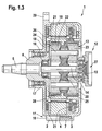
- FIG. 4 shows a schematic illustration of a circular thrust gear with a ring gear toothing which cooperates with an output spur gear.
- a circular thrust gear 60 comprises a thrust plate 61.
- a ring gear toothing 62 In the thrust plate 61 there is a ring gear toothing 62, the pitch circle of which is identified by reference numeral 63.
- the center of the ring gear toothing 62 in the interior of the thrust plate 61 is identified by reference numeral 64.
- the ring gear toothing 62 of the thrust plate 61 meshes with an output shaft 65, the axis of rotation 67 of which at a distance 70 eccentrically to the center 64 of the ring gear teeth 62 is arranged.
- the direction of rotation of the output shaft 65 with respect to its axis of rotation 67 is indicated by arrow 69.
- an external toothing 66 On the outside of the output shaft 65, an external toothing 66 is formed, the pitch circle of which is identified by reference numeral 68.
- the thrust plate 61 of the circular thrust gear 60 is movably received on a first crank 71, a second crank 72 and a third crank 73.
- the crank pins of the cranks 71, 72, 73 each lie on the inner sides 77 of openings 74, 75, 76 - which are designed as bores - of the thrust plate 61.
- the direction of rotation in which the cranks 71, 72, 73 are moved is indicated by the arrows above the crank pin of the cranks 71, 72, 73 in FIG. 4.
- Reference number 78 denotes a mirror plane which runs through the center 64 of the ring gear toothing 62 in the thrust plate 61 and runs through an eccentric axis center of one of the three cranks 71, 72, 73, in this case through the eccentric axis center of the second crank 72, which in this Trap serves as a drive crank.
- a high reduction ratio can be achieved with the circular thrust gear 60 shown schematically in FIG. 4, so that the use of a direct current motor (DC drive) is made possible and long drive trains with a large number of transmission components can be saved. This is favorable with regard to the space requirements of a wiper system drive below the windshield for applications in motor vehicles.
- DC drive direct current motor
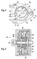
- Figure 5 shows an axial swash plate gear
- An axial swash plate gear designated by reference numeral 80 in FIG. 5 comprises a housing 81 which accommodates the gear components.
- the housing 81 of the axial wobble mechanism 80 surrounds a swash plate 82.
- the swash plate 82 is guided on the one hand in a swash plate guide 85 which is fixed to the housing and which forces the swash plate 82 to move.
- the swash plate 82 is also received by means of a swash plate bearing 83 on a drive 86 with an angled eccentric.
- the swash plate which is provided with a toothing on an end face facing an output gear 87, is in meshing engagement 88 with it, as a result of which the output axis 84 is moved.
- the axial swash plate or swash gear 80 has characteristics similar to a radially acting swash plate or swash gear.
- Swash plate or swash wheel gears are understood here to mean both axial and radial swash plate gears. Both versions of a swash plate or swash gear are common that they have high power density combined with a large variety of gear reduction.
- swash plate or swash gear 80 have an extremely simple structure, which makes them very robust, and good efficiency. Thereafter, wobble wheel or swash plate gears 80 are rotationally symmetrical, so that they can be integrated very well into the interior of a hollow output shaft 6 (see FIG. 1.3).
- FIGS. 6.1 and 6.2 A straight-toothed crown gear is shown in FIGS. 6.1 and 6.2.
- a rotationally symmetrical design of a wiper system drive cannot be achieved in principle, since the pinion shaft 95 of the electric drive 91 runs at an angle of 90 ° - here perpendicular to the plane of the drawing - to the axis of rotation 97 of a crown wheel segment 98.
- the crown wheel gear arrangement 90 shown in FIGS. 6.1 and 6.2 has considerable advantages due to its compact design compared to the use of a worm gear on which the drive and driven axes are also, for reasons of principle, also staggered by an angle of 90 ° to one another.
- a very compact design is achieved by the articulation of the crown wheel segment 96 directly on the housing 92 of the electric drive 91.
- the motor / gear unit 90, 91 can be mirror-symmetrical to the mirror plane 78 shown in FIG. 6.2.
- the arrangement of a motor gearbox unit for wiper systems shown in FIGS. 6.1 and 6.2 offers the advantage that in relation to a driver or a passenger side on a bulkhead below the assembly area of the windshield of a motor vehicle body, it is only necessary to twist the motor / gear arrangement 90 or 91 about its axis of symmetry 93, which considerably simplifies their installation.
- the crown gear 90 includes an electric drive 91 which can be designed as a DC motor, as an asynchronous or as a transverse flux motor. This is enclosed by a housing 92, which is rotationally symmetrical to the axis of symmetry 93. Due to the 90 ° orientation of the axis of rotation 97, which represents the output axis of the crown gear 90, and the pinion shaft 94 of the electric drive 91, a mirror-symmetrical construction of this motor / gear arrangement can be achieved.
- the crown gear segment 96 which pivots about the articulation point 97, which coincides with the output shaft of the crown gear 90, sweeps over a pivot angle of approximately 100 ° to 120 °. If the crown gear segment 96 is provided with a toothing 98, this is preferably formed as a degree toothing which meshes with the pinion 95 embodied on the motor shaft 94.
- the drives shown in Figures 1.1, 1.2, 1.3 and 3 and 5 are essentially rotationally symmetrical. These design variants of the wiper system drives proposed according to the invention facilitate the connection to the vehicle body, since the connection points (cf. positions 7, 8 and 9 in FIGS. 1.1, 1.2 and 1.3) can simply be copied. Accordingly, these can be designed identically on the driver and passenger side below a windshield in the body area of a vehicle body. A standardized connection requires little application effort.
- rotationally symmetrical drive units the output shaft 5 of which can be used directly to drive a wiper arm
- rotationally symmetrical drives 1 in two-motor systems or in direct wiper drives, the same drives can be used for the driver and front passenger. This means that the same components, the same flange patterns and the same standardized connection points can be formed on the driver and passenger side.
- the electrics or electronics of the drives with regard to connector design, control and regulation electronics and the connection to the vehicle electrical system or to a vehicle bus system (CAN bus) can be considerably simplified, since these interfaces and the components used can be designed identically.
- a mirror-symmetrical arrangement of a wiper drive unit is possible if the output axis - as shown - lies in the mirror plane 78.
- This can considerably simplify the assembly of such mirror-symmetrically constructed wiper drive units, since for mounting on the driver or passenger side below a windshield in the front region of a motor vehicle body, only a rotation of the drive units 60 and 90 about their axes of symmetry (cf. 93 according to FIGS. 6.1 and 6.2) is required and the other connection components, such as connection point for on-board electrical system voltage, connection point of the bus system (CAN data bus), control and regulating electronics, can otherwise be designed identically.
Landscapes
- Engineering & Computer Science (AREA)
- Mechanical Engineering (AREA)
- General Engineering & Computer Science (AREA)
- Power Engineering (AREA)
- Connection Of Motors, Electrical Generators, Mechanical Devices, And The Like (AREA)
Abstract
Description
An Fahrzeugen kommen zur Reinigung von Sicht-, Scheinwerfer- und Spiegel Scheibenwischer zum Einsatz. Der Antrieb der Wischer erfolgt üblicherweise durch Elektroantriebe und verschiedenartige, mit den Elektroantrieben zusammenwirkende Getriebe, wie zum Beispiel Wischergestänge. Bei Heckscheibenwischern an Kraftfahrzeugen kommt heute meist ein Einzelwischer zum Einsatz, während zur Reinigung von Frontscheiben an Straßen- oder Schienenfahrzeugen zweiarmige Fensterscheibenwischer zum Einsatz kommen. Werden zum Antrieb der Frontscheibenwischer zwei Motoren eingesetzt, sind für die Antriebe in der Regel unterschiedlich ausgeführte Varianten sowohl auf der Fahrer- als auch auf der Beifahrerseite des Fahrzeugs erforderlich.Vehicle wipers are used to clean sight, headlight and mirror wipers. The wipers are usually driven by electric drives and various types of gear which interact with the electric drives, such as wiper linkages. In the case of rear window wipers on motor vehicles, a single wiper is usually used today, while two-armed window wipers are used for cleaning front windows on road or rail vehicles. If two motors are used to drive the windscreen wipers, different versions are usually required for the drives, both on the driver and the passenger side of the vehicle.
DE 196 42 667 A1 bezieht sich auf eine Lagerung für einen Wischerantrieb. Eine Wischeranlage an einem Fahrzeug wird mittels eines Wischerantriebes angetrieben. Die Wischeranlage umfaßt eine Rohrplatine, welche den Wischerantrieb mit einer in einem Lagerstutzen geführten Antriebswelle aufnimmt. Der Wischerantrieb ist gemäß dieser Lösung mit dem Lagerstutzen in ein an der Rohrplatine angeordnetes rohrförmiges Element eingesteckt. Das rohrförmige Element wird an der Rohrplatine angeformt, wobei der Lagerstutzen des Wischerantriebes durch die Rohrplatine gesteckt wird. Der Wischerantrieb ist in Umfangsrichtung durch Kraftschluß zwischen dem Lagerstutzen und dem rohrförmigen Element auf der Rohrplatine fixiert, kann jedoch auch durch Formschluß in Umfangsrichtung zwischen dem Lagerstutzen und dem rohrförmigen Element fixiert sein.DE 196 42 667 A1 relates to a bearing for a wiper drive. A wiper system on a vehicle is driven by a wiper drive. The wiper system comprises a tube plate which receives the wiper drive with a drive shaft guided in a bearing socket. According to this solution, the wiper drive is inserted with the bearing socket into a tubular element arranged on the tube board. The tubular element is molded onto the tube board, the bearing socket of the wiper drive being inserted through the tube board. The wiper drive is fixed in the circumferential direction by frictional connection between the bearing socket and the tubular element on the tube board, but can also be fixed in the circumferential direction between the bearing socket and the tubular element by positive locking.
Das rohrförmige Element kann eine von der Kreisform abweichende, insbesondere polygonförmige oder unrunde Innenkontur aufweisen, die mit einer passenden Außenkontur des Lagerstutzens korrespondiert. Eine Fixierung zwischen dem Lagerstutzen des Wischerantriebes und dem rohrförmigen Element kann auch über eine Verzahnung erfolgen.The tubular element can have an inner contour that deviates from the circular shape, in particular a polygonal or non-circular one, with an appropriate outer contour of the Bearing neck corresponds. A fixation between the bearing socket of the wiper drive and the tubular element can also be done via a toothing.
Die in DE 196 42 667 A1 dargestellte Lösung erfordert zwei konstruktiv unterschiedlich ausgeführte Varianten für die Fahrer- bzw. Beifahrerseite eines Fahrzeuges bzw. eines Schienenfahrzeuges sowie an die konstruktiv unterschiedlich ausgeführte Variante angepaßte Gestänge, die ebenfalls nicht spiegelsymmetrisch sind. Dies erfordert die Bereitstellung mindestens zweier Varianten von Wischgestängen bzw. Frontwischerantrieben oder Scheinwerferwischerantrieben für die Fahrer- bzw. für die Beifahrerseite.The solution shown in DE 196 42 667 A1 requires two structurally different designs for the driver or front passenger side of a vehicle or a rail vehicle, and linkages adapted to the structurally different design, which are also not mirror-symmetrical. This requires the provision of at least two variants of wiper linkages or front wiper drives or headlight wiper drives for the driver or for the passenger side.
Aufgrund des zwangsweisen, prinzipienbedingten Versatzes von Antriebs- und Antriebsachse eines Schneckengetriebes ist es erforderlich, sowohl für die Fahrer- als auch für die Beifahrerseite unterschiedliche Aufnahmen für diese Getriebebauart zu schaffen. Darüber hinaus benötigen Schneckengetriebe aufgrund des zwangsweisen Versatzes von Antriebsund Abtriebswelle relativ viel Bauraum.Due to the compulsory, principle-related offset of the drive and drive axles of a worm gear, it is necessary to create different receptacles for this type of gear for both the driver and the passenger side. In addition, worm gears require a relatively large amount of installation space due to the forced misalignment of the input and output shafts.
Mit der erfindungsgemäß vorgeschlagenen Lösung wird ein Wischerantrieb bereitgestellt, der sich insbesondere in Hohlwellen integrieren läßt. Aufgrund des spiegelsymmetrischen Aufbaus des vorgeschlagenen Wischerantriebes liegt die Abtriebsachse dieses Wischerantriebes in der Spiegelebene bzw. die Abtriebsachse im Zentrum des rotationssymmetrischen Bauteils. Wird die Abtriebsachse des Wischerantriebes insbesondere direkt zum Antrieb eines Wischers oder eines Wischerarmes eingesetzt, entsteht ein extrem kompakt bauender Wischerdirektantrieb (WDA). Der spiegelsymmetrische Aufbau des erfindungsgemäß vorgeschlagenen Wischerantriebes bietet erhebliche Vorteile hinsichtlich des beanspruchten Einbauraumes und ermöglicht Kosteneinsparungen.With the solution proposed according to the invention, a wiper drive is provided which can be integrated in particular into hollow shafts. Due to the mirror-symmetrical structure of the proposed wiper drive, the output axis of this wiper drive lies in the mirror plane or the output axis lies in the center of the rotationally symmetrical component. If the output axis of the wiper drive is used directly to drive a wiper or wiper arm, an extremely compact direct wiper drive (WDA) is created. The mirror-symmetrical structure of the wiper drive proposed according to the invention offers considerable advantages with regard to the installation space required and enables cost savings.
Werden Zweimotorenwischeranlagen bzw. die oben erwähnten Wischerdirektantriebe eingesetzt, lassen sich für die Fahrer- und die Beifahrerseite identische Antriebe einsetzen. Dies bedeutet, daß lediglich ein Bauteil gefertigt, gekennzeichnet, gelagert, verpackt und transportiert werden muß, was neben den Fertigungskosten die Logistikkosten erheblich reduziert. Insbesondere lassen sich die karosserieseitigen Anschlußstellen für rotations- bzw. spiegelsymmetrische Wischerantriebe (oder auch Wischerdirektantriebe) standardisieren, so daß identische Flanschbilderbohrungen bzw. Aufnahmeflächen vorgesehen werden können, die auf fahrer- bzw. beifahrerseitiger Montagestelle des Wischerantriebes identisch sind. Daneben können auch die elektrischen Verbindungen bzw. die Elektronik der Antriebe, Stecker, Steuer und Regelungselektronik sowie die Anbindung an das fahrzeugeigene Bordnetz bzw. das fahrzeugeigene Bussystem (CAN-Bus) identisch ausgelegt werden.If two-motor wiper systems or the above-mentioned direct wiper drives are used, identical drives can be used for the driver and the passenger side. This means that only one component has to be manufactured, labeled, stored, packaged and transported, which in addition to the manufacturing costs significantly reduces the logistics costs. In particular, the body-side connection points for rotationally or mirror-symmetrically wiper drives (or also wiper direct drives) can be standardized so that identical flange pattern bores or mounting surfaces can be provided which are identical on the driver's or passenger's mounting point of the wiper drive. In addition, the electrical connections and electronics of the drives, Connectors, control and regulating electronics as well as the connection to the vehicle's on-board electrical system or the vehicle's own bus system (CAN bus) are designed identically.
Das Anbindungskonzept hinsichtlich der Verwendung spiegelsymmetrisch aufgebauter Wischerantriebe bzw. Wischerdirektantriebe kann standardisiert und damit die Applikationskonstruktion - etwa beim Automobilhersteller - und der Einbau wesentlich vereinfacht werden. Rationalisierungseffekte bzw. Rationalisierungspotential bei der erfindungsgemäß vorgeschlagenen Lösung sind vor allem darin zu erblicken, daß durch die Verwendung gleicher Bauweisen für verschiedene Antriebe - seien es Front- und Heckwischer, seien es Scheinwerferwischer - auf identische Bauteile zurückgegriffen werden kann. Handelt es sich beim eingesetzten Wischerantrieb um ein rotationssymmetrisches Bauteil und eine lernfähige Elektronik, die optional eine Positionserfassung umfassen kann, lassen sich bei allen Wischerantrieben zusätzliche Vereinfachungen beim Einbau realisieren, da dann die Lage von Antrieb und Wischhebel bzw. einer anderen Wischarmkomponente zueinander beim Zusammenbau beliebig ist. Dies bedeutet hinsichtlich des Einbaus in der Endmontage eine erhebliche Montageerleichterung, da einerseits eine geringere Einbau- und ein geringere Taktzeit erreichbar ist und andererseits weniger Einbaufehler auftreten können.The connection concept with regard to the use of mirror-symmetrically constructed wiper drives or direct wiper drives can be standardized and thus the application design - for example at the automobile manufacturer - and installation can be considerably simplified. Rationalization effects or rationalization potential in the solution proposed according to the invention can be seen above all in the fact that by using the same construction methods for different drives - be it front and rear wipers or headlight wipers - identical components can be used. If the wiper drive used is a rotationally symmetrical component and teachable electronics, which can optionally include position detection, all wiper drives can be further simplified during installation, since the drive and wiper arm or another wiper arm component can be in any position relative to one another during assembly is. With regard to the installation in the final assembly, this makes installation considerably easier, since on the one hand a shorter installation and a shorter cycle time can be achieved and on the other hand fewer installation errors can occur.
Anhand der Zeichnung wird die Erfindung nachstehend eingehender beschrieben.The invention is described in more detail below with reference to the drawing.
Es zeigt:
- Figuren 1.1 bis 1.3
- eine Draufsicht, eine Seitenansicht und eine Schnittdarstellung eines rotationssymmetrischen Wischerantriebes,
Figur 2- einen Schnitt durch ein platzsparend aufgebautes rotationssymmetrisches Planetengetriebe,
Figur 3- ein rotationssymmetrisch aufgebautes Wellgetriebe,
Figur 4- eine schematische Darstellung eines Kreisschubgetriebes mit einer Hohlverzahnung, die mit einem Abtriebsstirnrad zusammenarbeitet,
Figur 5- ein axiales Taumelscheibengetriebe und die
- Figuren 6.1 u. 6.2
- ein Kronradgetriebe mit Geradverzahnung
- Figures 1.1 to 1.3
- a plan view, a side view and a sectional view of a rotationally symmetrical wiper drive,
- Figure 2
- a section through a space-saving rotationally symmetrical planetary gear,
- Figure 3
- a rotationally symmetrical wave gear,
- Figure 4
- 1 shows a schematic illustration of a circular thrust gear with a hollow toothing which cooperates with an output spur gear,
- Figure 5
- an axial swash plate gear and the
- Figures 6.1 u. 6.2
- a crown gear with straight teeth
Figur 1.1 bis 1.3 zeigt eine Draufsicht, eine Seitenansicht und eine Rückansicht eines rotationssymmetrischen Wischerantriebes.Figure 1.1 to 1.3 shows a plan view, a side view and a rear view of a rotationally symmetrical wiper drive.
Gemäß dieser Ausführung der erfindungsgemäß vorgeschlagenen Lösung umfaßt eine rotationssymmetrisch ausgebildete Antriebseinheit 1 einen BPM-Motor (Brushless Permanent Magnet), bei dem es sich um einen elektronisch kommutierten, ohne Bürsten arbeitenden Elektromotor mit Permanentmagneten ohne geschaltete Reluktanz handelt. Elektronisch kommutierte (EC-Motoren) sind als rotationssymmetrische Antriebseinheiten 1 besonders interessant, weil alternative Bauformen möglich sind, die oft interessant sind wegen des zur Verfügung stehenden Bauraumes. So lassen sich diese rotationssymmetrischen Antriebe 1 relativ flach bei großem Durchmesser ausbilden. Die Elektronik solcher EC-Motoren ist sehr einfach mit den Datenbussen (CAN-Datenbussen) des Kraftfahrzeuges verbindbar; es entsteht kein zusätzlicher Schaltungsaufwand. Da die EC-Motoren aufgrund ihres Konstruktionsprinzipes keine Bürsten aufweisen, stellt sich demzufolge kein Verschleiß an diesen Bauteilen ein, was vorteilhaft bei häufig laufenden Motoren ist. Ferner entsteht aufgrund der fehlenden Bürsten an solcherart ausgebildeten, elektrisch kommutierenden Motoren keine Funkenbildung, was zu Abrasion, Verschleiß und damit zu vorzeitigem Ausfall bisher eingesetzter Antriebe führt. Aufgrund des Einsatzes von EC-Motoren wird eine Funkenbildung vermieden. Da aufgrund fehlender Funkenbildung an EC-Motoren keine Funkwellen auftreten, stellen EC-Motoren auch keine Störstrahlungsquellen dar. Ferner ist aufgrund der fehlenden Funkenbildung an EC-Motoren deren elektromagnetische Verträglichkeit (EMV) erheblich günstiger, verglichen mit Bürsten aufweisenden elektrischen AntriebenAccording to this embodiment of the solution proposed according to the invention, a rotationally
Der rotationssymmetrische Antrieb 1 umfaßt eine erste Gehäuseschale 2 und eine zweite Gehäuseschale 3, die entlang einer ringförmig ausgebildeten Fuge 4 miteinander verbunden sind. Die Abtriebswelle des rotationssymmetrischen Antriebes 1 ist mit Bezugszeichen 5 gekennzeichnet und durchsetzt die erste Gehäuseschale 2. Die Abtriebswelle 5 des rotationssymmetrischen Antriebseinheit 1 ist von einer Abtriebshohlwelle 6 umschlossen. An der Außenumfangsfläche der Gehäuseschalen 2 und 3 sind in der Ausführungsvariante der rotationssymmetrischen Antriebseinheit 1 gemäß der Darstellung in Figur 1.1 drei um einen Winkel von etwa 120° zueinander versetzt ausgebildete Verbindungsstellen 7, 8 und 9 angeordnet. Die Verbindungsstellen 7, 8 und 9 liegen jeweils miteinander fluchtend in einem Winkel von 120° zueinander versetzt an den Außenumfängen sowohl der ersten Gehäuseschale 2 als auch der zweiten Gehäuseschale 3. Die Verbindungsstellen 7, 8 und 9 umfassen jeweils eine Bohrung 10 sowie fluchtend zu den Verbindungsstellen 7, 8 und 9 an der ersten Gehäuseschale 1 ausgebildete Aussparungen 11.The rotationally
Aus der Seitenansicht der rotationssymmetrischen Antriebseinheit 1 gemäß der Darstellung in Figur 1.2 geht hervor, daß an der Rückseite der zweiten Gehäuseschale 3 ein Sensorelement 12 angeordnet ist. Dieses Sensorelement 12 kann beispielsweise als ein AMR-Sensorelement ausgebildet sein, welches gleichzeitig eine rotationssymmetrisch liegende Anschlußstelle 27 für eine Steuer- und Regelungselektronik darstellt, die in der Seitenansicht gemäß Figur 1.2 angedeutet ist. Ist die mit der rotationssymmetrischen Antriebseinheit 1 verbindbare Steuer- und Regelungselektronik als eine lemfähige Elektronik (optional mit Positionserfassung) ausgebildet, können bei Einbau der in Figur 1.2 dargestellten rotationssymmetrischen Antriebseinheit 1 zusätzliche Vereinfachungen beim Einbau realisiert werden, da die Lage der rotationssymmetrischen Antriebseinheit 1 und die Lage der Wischerkomponente, beispielsweise eines Wischerhebels, zueinander beim Zusammenbau beliebig sein können. Dies stellt eine erhebliche Montageerleichterung beim Einbau dar, da sich dadurch geringere Einbau- bzw. Taktzeiten und weniger Einbaufehler durch Abstimmung der Lage von Antriebseinheit und Wischhebel zueinander erzielen lassen.It can be seen from the side view of the rotationally
Aus der Seitenansicht gemäß Figur 1.2 der rotationssymmetrischen Antriebseinheit 1 geht darüber hinaus hervor, daß im Bereich einer Stirnseite der ersten Gehäuseschale 2 in Umfangsrichtung der ersten Gehäuseschale 2 gesehen, zu den Verbindungsstellen 7, 8 und 9 korrespondierend ausgebildete Anlageflächen angeordnet sind. Über diese Anlagefläche kann eine Montage der rotationssymmetrischen Antriebseinheit 1 an einer Spritzwand bzw. einer Stirnwand auf Fahrer- und Beifahrerseite einer Kfz-Karosserie erfolgen, gegebenenfalls unter Zwischenschaltung eines in Figur 1.2 nicht dargestellten Dichtelementes.The side view according to FIG. 1.2 of the rotationally
Figur 1.3 zeigt eine Schnittdarstellung eines rotationssymmetrischen Antriebes, der als Wischerantrieb eingesetzt werden kann.Figure 1.3 shows a sectional view of a rotationally symmetrical drive that can be used as a wiper drive.
Aus der Schnittdarstellung gemäß Figur 1.3 geht hervor, daß die erste Gehäuseschale 2 und die zweite Gehäuseschale 3 der rotationssymmetrischen Antriebseinheit 1 ein integriertes Planetengetriebe 13 umschließen. Eine Welle 14 ist in einem ersten Lager 15 und einem zweiten Lager 16 drehbar aufgenommen. Das erste Lager 15 befindet sich in der zweiten Gehäuseschale 3, während das zweite Lager 16 im Inneren einer Abtriebshohlwelle 6 aufgenommen ist.1.3 shows that the
An der Außenfläche der ersten Gehäuseschale 2 und der zweiten Gehäuseschale 3 befinden sich die in den Figuren 1.1 bzw. 1.2 dargestellten Verbindungsstellen 7, 8, 9, von denen hier lediglich die erste Verbindungsstelle 7 dargestellt ist. Diese umfaßt eine Bohrung 10, die sich durch die erste Verbindungsstelle 7 in der ersten und in der zweiten Gehäuseschale 2 bzw. 3 erstreckt und an der Stirnseite der ersten Gehäuseschale 2 in eine Aussparung 11 übergeht. Die Verbindungsstellen der miteinander an der Fuge 4 gefügten ersten und zweiten Gehäuseschale können auch, wie im oberen Bereich von Figur 1.3 dargestellt, als Flanschbohrungen ausgebildet sein. Entsprechend des Flanschbildes der rotationssymmetrischen Antriebseinheit 1 gemäß der Darstellung in Figur 1.3 können Verbindungsstellen 29 der rotationssymmetrischen Antriebseinheit 1 mit der Kfz-Karosserie standardisiert ausgeführt werden und auf Fahrer- und Beifahrerseite der Kfz-Karosserie identisch ausgebildet werden, was den Montageaufwand erleichtert und ferner eine größere Freiheit bei der Handhabung der rotationssymmetrischen Antriebseinheit 1 bei deren Montage in dem Bereich, in welchem Motor und Fahrgastraum eines Fahrzeugs aneinandergrenzen, gestattet. Ferner läßt sich die Handhabung einer rotationssymmetrischen Antriebseinheit 1 bei der Montage an einer Fahrzeugscheibe erheblich verbessern.On the outer surface of the
Die Abtriebshohlwelle 6 ihrerseits ist mittels eines Hohlwellenlagers 17 in der ersten Gehäuseschale 2 gelagert. Über eine Verstiftung 18 ist an der Abtriebshohlwelle 6 ein erster Zahnkranz 19 drehfest aufgenommen, der mit einer kranzförmig verlaufenden Innenverzahnung ausgeführt ist.The
Die Innenverzahnung des ersten Zahnkranzes 19 kämmt mit ersten Planetenrädern 22, die an einer Planetenradwelle 24 aufgenommen sind. Die Planetenradwelle 24 ihrerseits ist in einer an der Welle 14 aufgenommenen Trägerscheibe 20 gelagert, die an ihrem Außenumfang mit einem als Rotor fungierenden, mit Magneten ausgestatteten Kranz 28 versehen ist. Der Kranz 28 bildet den Rotor. Der Stator der rotationssymmetrischen Antriebseinheit 1 gemäß der Darstellung in Figur 1.3 wird durch im Inneren der ersten Gehäuseschale 2 drehfest angeordnete Wicklungen 21 gebildet. Auf dem den ersten Planetenrädern 22 gegenüberliegenden Ende der Planetenradwelle 24 sind zweite Planetenräder 23 aufgenommen, die in einem etwas vergrößerten Durchmesser ausgeführt sind. Die zweiten Planetenräder 23 können jedoch auch im zu den ersten Planetenrädern 23 korrespondierenden Durchmesser oder einem anderen Durchmesser ausgeführt sein. Die zweiten Planetenräder 23 der rotationssymmetrischen Antriebseinheit 1 gemäß der Darstellung in Figur 1.3 kämmen mit einem innenverzahnten zweiten Zahnkranz 25. Der zweite Zahnkranz 25 ist hinsichtlich seines Teilkreisdurchmessers auf den jeweiligen Durchmesser der zweiten Planetenräder 23 abgestimmt. Der zweite Zahnkranz 25 ist drehfest innerhalb der zweiten Gehäuseschale 3 aufgenommen. Mit Bezugszeichen 26 ist ein Rückschlußring für die Abtriebshohlwelle 6 bezeichnet.The internal toothing of the
Gemäß der Ausführungsvariante der rotationssymmetrischen Antriebseinheit 1 nach Figur 1.3 befindet sich innerhalb des Sensorelementes 12 an der rückwärtigen Stirnseite der zweiten Gehäuseschale 3 der Anschluß 27 für die Ansteuerelektronik. Dieser liegt damit ebenfalls koaxial zur Symmetrieachse der Abtriebswelle 5 und der Welle 14 des integrierten Planetengetriebes 13, so daß die Ansteuerelektronik für die rotationssymmetrische Antriebseinheit 1 gemäß der Schnittdarstellung in Figur 1.3 ohne zusätzlichen Aufwand auf Fahrer- und Beifahrerseite identisch ausgebildet werden kann.According to the embodiment variant of the rotationally
Figur 2 zeigt einen Querschnitt durch ein platzsparend aufgebautes rotationssymmetrisches Kronradgetriebe.Figure 2 shows a cross section through a space-saving rotationally symmetrical crown gear.
Die rotationssymmetrisch ausgebildete Antriebseinheit 30 ist gemäß der Ausführungsvariante nach Figur 2 als Elektroantrieb mit integriertem Planetengetriebe ausgebildet. Das Planetengetriebe 30 umfaßt gemäß dieser Ausführungsvariante einer rotationssymmetrischen Antriebseinheit Kronräder.The rotationally
Das Planetengetriebe 30 mit Kronrädern umfaßt einen Elektroantrieb 31. Der Elektroantrieb 31 umfaßt einen Stator 42, dem ein Rotor 39 gegenüberliegt. Ein erstes Planetenrad 34 und ein zweites Planetenrad 35 sind auf einer gemeinsamen Planetenradwelle 36 aufgenommen. Die Planetenradwelle 36 ist einerseits in einem Mantel 38 und andererseits in einer Nabe 37 drehbar aufgenommen. Die ersten Planetenräder 34 kämmen mit der Verzahnung eines ersten Kronrades 32, während die zweiten Planetenräder 35 mit der Verzahnung eines zweiten Kronrades 33 kämmen. Das erste Kronrad 32 ist innerhalb eines Gehäusedeckels 43 integriert, innerhalb dessen eine Abtriebswelle 40, aufgenommen durch ein Wälzlager, drehbar angeordnet ist. Das erste Kronrad 32 dient als Antriebskronrad, während das zweite Kronrad 33 drehfest an der Abtriebswelle 40 aufgenommen ist und über die als Abtriebsritzel fungierenden, an der gemeinsamen Planetenradwelle 36 aufgenommenen zweiten Planetenräder 35 angetrieben wird. Das zweite Kronrad 33 rotiert mit der Abtriebsdrehzahl. Die Drehachse, um welche die ersten und zweiten Planetenräder 34 bzw. 35 rotieren, ist mit Bezugszeichen 46 gekennzeichnet, während dazu senkrecht verlaufend eine zweite Drehachse der Abtriebswelle 40, die mit der Drehachse des zweiten Kronrades 33 zusammenfällt, durch Bezugszeichen 47 gekennzeichnet ist. Die erste Drehachse 46 fällt mit der Symmetrieachse der Planetenradwelle 36 zusammen, während die zweite Drehachse 47 mit der Symmetrielinie der Abtriebswelle 40 zusammenfällt.The
In einem dem Gehäusedeckel 43 gegenüberliegenden weiteren Deckelelement sind Steuereinheiten 44 gelagert. An diesem Deckelelement ist ebenfalls eine Kühlrippe 45 vorgesehen, welche zur Abfuhr der entstehenden Wärme dient. Ferner ist im weiteren Deckelelement eine Lagerhülse 41 aufgenommen, die die zweite Drehachse 47 umschließt.
Figur 3 ist eine schematische Darstellung eines rotationssymmetrisch bauenden Wellgetriebes zu entnehmen.FIG. 3 shows a schematic illustration of a rotationally symmetrical shaft gear.
Neben der in Figur 1 dargestellten Ausbildung einer rotationssymmetrischen Antriebseinheit mit einem integrierten Planetengetriebe 13 kann die rotationssymmetrisch ausgebildete Antriebseinheit 1 ein Wellgetriebe 50 umfassen. Wellgetriebe 50 eignen sich insbesondere für rotationssymmetrisch bauende Antriebe, weil sie selbst symmetrisch aufgebaut sind, wobei An- und Abtriebsachse koaxial zueinander verlaufen. Wellgetriebe 50 bauen sehr kompakt, wobei ein sehr breites Untersetzungsband zur Verfügung gestellt wird (ab ca. 1:30 bis ca. 1:300). In der Regel sind Wellgetriebe 50 selbsthemmend ausgebildet. Auch diese Ausführungsvariante einer rotationssymmetrischen Antriebseinheit 1 gestattet identische Anschlußstellen an der vorderen Spritzwand einer Kfz-Karosserie und erhöht die Freiheitsgrade bei der Montage als Wischerantrieb erheblich.In addition to the design of a rotationally symmetrical drive unit with an integrated
Das Wellgetriebe 50 gemäß der schematischen Wiedergabe in Figur 3 umfaßt eine Abtriebswelle 5, die koaxial zur Motorwelle eines in Figur 3 nicht dargestellten elektrischen Antriebes liegt. Das Wellgetriebe 50 umfaßt eine erste Gehäuseschale 2 sowie eine zweite Gehäuseschale 3, wobei in der Darstellung gemäß Figur 3 die erste Gehäuseschale 2 von der zweiten Gehäuseschale 3 abgenommen ist. Die an einer Karosseriewandung unterhalb der Windschutzscheibe des Kraftfahrzeuges anliegende Stirnseite des Wellgetriebes 50 ist mit Bezugszeichen 51 gekennzeichnet.The
Figur 4 ist eine schematische Darstellung eines Kreisschubgetriebes mit einer Hohlradverzahnung zu entnehmen, die mit einem Abtriebsstirnrad zusammenarbeitet.FIG. 4 shows a schematic illustration of a circular thrust gear with a ring gear toothing which cooperates with an output spur gear.
Ein Kreisschubgetriebe 60 umfaßt eine Schubplatte 61. In der Schubplatte 61 ist eine Hohlradverzahnung 62 ausgeführt, deren Teilkreis mit Bezugszeichen 63 gekennzeichnet ist. Das Zentrum der Hohlradverzahnung 62 im Inneren der Schubplatte 61 ist mit Bezugszeichen 64 gekennzeichnet. Die Hohlradverzahnung 62 der Schubplatte 61 kämmt mit einer Abtriebswelle 65, deren Rotationsachse 67 in einem Abstand 70 exzentrisch zum Zentrum 64 der Hohlradverzahnung 62 angeordnet ist. Der Drehsinn der Abtriebswelle 65 in Bezug auf ihre Rotationsachse 67 ist mit Pfeil 69 bezeichnet. An der Außenseite der Abtriebswelle 65 ist eine Außenverzahnung 66 ausgebildet, deren Teilkreis mit Bezugszeichen 68 gekennzeichnet ist.A
Die Schubplatte 61 des Kreisschubgetriebes 60 ist an einer ersten Kurbel 71, einer zweiten Kurbel 72 sowie an einer dritten Kurbel 73 bewegbar aufgenommen. Die Kurbelzapfen der Kurbeln 71, 72, 73 liegen jeweils an Innenseiten 77 von Öffnungen 74, 75, 76 - die als Bohrungen beschaffen sind - der Schubplatte 61 an. Der Drehsinn, in welchem die Kurbeln 71, 72, 73 bewegt werden, ist durch die Pfeile oberhalb der Kurbelzapfen der Kurbeln 71, 72, 73 in Figur 4 angedeutet. Mit Bezugszeichen 78 ist eine Spiegelebene gekennzeichnet, die durch das Zentrum 64 der Hohlradverzahnung 62 in der Schubplatte 61 verläuft und durch einen Exzenterachsenmittelpunkt einer der drei Kurbeln 71, 72, 73 verläuft, in diesem Falle durch den Exzenterachsenmittelpunkt der zweiten Kurbel 72, die in diesem Falle als Antriebskurbel dient.The
Mit dem in Figur 4 schematisch dargestellten Kreisschubgetriebe 60 läßt sich eine hohe Untersetzung erreichen, so daß die Verwendung eines Gleichstrom-Motors (DC-Antrieb) ermöglicht wird und lang ausgebildete Antriebsstränge mit einer Vielzahl von Übertragungskomponenten eingespart werden können. Dies ist günstig hinsichtlich der Bauraumbeanspruchung eines Wischanlagenantriebes unterhalb der Windschutzscheibe bei Applikationen in Kraftfahrzeugen.A high reduction ratio can be achieved with the
Figur 5 zeigt ein axiales Taumelscheibengetriebe.Figure 5 shows an axial swash plate gear.
Ein in Figur 5 mit Bezugszeichen 80 bezeichnetes axiales Taumelscheibengetriebe umfaßt ein Gehäuse 81, welches die Getriebekomponenten aufnimmt. Das Gehäuse 81 des axialen Taumelgetriebes 80 umschließt eine Taumelscheibe 82. Die Taumelscheibe 82 ist einerseits in einer eine Nut enthaltenden gehäusefesten Taumelscheibenführung 85 geführt, welche der Taumelscheibe 82 ihre Bewegung aufzwingt. Die Taumelscheibe 82 ist darüber hinaus mittels Taumelscheibenlager 83 auf einem Antrieb 86 mit integriertem abgewinkelt ausgebildeten Exzenter aufgenommen. Die Taumelscheibe, welche an einer einem Abtriebsrad 87 zuweisenden Stirnseite mit einer Verzahnung ausgebildet ist, steht mit diesem in Verzahnungseingriff 88, wodurch die Abtriebsachse 84 bewegt wird. Das axiale Taumelscheiben- oder Taumelradgetriebe 80 besitzt ähnliche Charakteristika wie ein radial wirkendes Taumelscheiben- oder Taumelradgetriebe. Unter Taumelscheiben- bzw. Taumelradgetrieben werden hier sowohl axiale wie auch radiale Taumelscheibengetriebe verstanden. Beiden Ausführungsvarianten eines Taumelscheiben- bzw. Taumelradgetriebes ist gemeinsam, daß sie hohe Leistungsdichte, verbunden mit einer großen Untersetzungsvielfalt aufweisen. Ferner weisen Taumelscheiben- bzw. Taumelradgetriebe 80 einen extrem einfachen Aufbau, der sie sehr robust macht, sowie einen guten Wirkungsgrad auf. Danach sind Taumelrad- bzw. Taumelscheibengetriebe 80 rotationssymmetrisch aufgebaut, so daß sie sich sehr gut in das Innere einer Abtriebshohlwelle 6 (vgl. Figur 1.3) integrieren lassen.An axial swash plate gear designated by
Den Figuren 6.1 bzw. 6.2 ist ein gradverzahntes Kronradgetriebe zu entnehmen.A straight-toothed crown gear is shown in FIGS. 6.1 and 6.2.
In dieser Ausführungsvariante einer Antriebseinheit für Wischanlagen läßt sich eine rotationssymmetrische Ausbildung eines Wischanlagenantriebes prinzipbedingt nicht erreichen, da die Ritzelwelle 95 des Elektroantriebes 91 in einem Winkel von 90° - hier senkrecht zur Zeichenebene verlaufend - zur Drehachse 97 eines Kronradsegmentes 98 verläuft. Die in den Figuren 6.1 bzw. 6.2 dargestellte Kronradgetriebeanordnung 90 hat jedoch aufgrund ihrer kompakten Bauweise erhebliche Vorteile gegenüber dem Einsatz eines Schneckengetriebes, an dem Antriebs- und Abtriebsachse prinzipbedingt ebenfalls zwangsweise um einen Winkel von 90° zueinander versetzt angeordnet sind. Durch die Anlenkung des Kronradsegmentes 96 unmittelbar am Gehäuse 92 des Elektroantriebes 91 wird eine sehr kompakte Bauform erreicht. Ist eine Verzahnung 98 am Kronradsegment 96 darüber hinaus als Gradverzahnung ausgebildet, kann die Motor/Getriebeeinheit 90, 91 spiegelsymmetrisch zur in Figur 6.2 dargestellten Spiegelebene 78 ausgebildet werden. Wenngleich nicht rotationssymmetrisch aufgebaut, vgl. die Motor/Getriebeeinheiten gemäß der Figuren 1.1, 1.2, 1.3, 2, 3 und 5, so bietet die in Figur 6.1 bzw. 6.2 dargestellte Anordnung einer Motor-Getriebeeinheit für Wischanlagen den Vorteil, daß auf einer Fahrer- bzw. einer Beifahrerseite in Bezug auf eine Spritzwand unterhalb des Montagebereiches der Windschutzscheibe einer Kfz-Karosserie lediglich eine Verdrehung der Motor/Getriebeanordnung 90 bzw. 91 um deren Symmetrieachse 93 erforderlich ist, was deren Einbau erheblich vereinfacht. Das Kronradgetriebe 90 umfaßt einen Elektroantrieb 91, der als DC-Motor, als Asynchronoder als Transversalflußmotor ausgebildet werden kann. Dieser ist von einem Gehäuse 92 umschlossen, welches rotationssymmetrisch zur Symmetrieachse 93 ausgebildet ist. Aufgrund der 90°-Orientierung der Drehachse 97, welche die Abtriebsachse des Kronradgetriebes 90 darstellt, und der Ritzelwelle 94 des Elektroantriebes 91, läßt sich jedoch ein spiegelsymmetrischer Aufbau dieser Motor/Getriebeanordnung erreichen. Das Kronradsegment 96, welches um den Anlenkpunkt 97 schwenkt, der mit der Abtriebswelle des Kronradgetriebes 90 zusammenfällt, überstreicht einen Schwenkwinkel von etwa 100° bis 120°. Ist das Kronradsegment 96 mit einer Verzahnung 98 versehen, wird diese vorzugsweise als Gradverzahnung ausgebildet, welche mit dem an der Motorwelle 94 ausgeführten Ritzel 95 kämmt.In this embodiment variant of a drive unit for wiper systems, a rotationally symmetrical design of a wiper system drive cannot be achieved in principle, since the
Die in den Figuren 1.1, 1.2, 1.3 sowie 3 und 5 dargestellten Antriebe sind im wesentlichen rotationssymmetrisch ausgebildet. Diese Ausführungsvarianten der erfindungsgemäß vorgeschlagenen Wischanlagenantriebe erleichtern die Anbindung an die Fahrzeugkarosserie, da die Anbindungspunkte (vgl. Position 7, 8 und 9 in Figuren 1.1, 1.2 und 1.3) einfach kopiert werden können. Diese können demnach auf Fahrer- und Beifahrerseite unterhalb einer Windschutzscheibe im Karosseriebereich einer Fahrzeugkarosserie identisch ausgebildet werden. Eine standardisierte Anbindung benötigt wenig Applikationsaufwand. Darüber hinaus können bei Zuordnung lemfähiger Elektronikkomponenten zu den rotationssymmetrisch ausgebildeten Antriebseinheiten die Freiheitsgrade hinsichtlich einer Montage der Antriebe in Bezug auf Wischkomponenten, wie zum Beispiel Wischhebel, erheblich vereinfacht werden, was eine erhebliche Reduzierung von Ein- und Zusammenbauzeiten bei der Montage der Wischerkomponenten einer Wischanlage nach sich zieht. Im Falle des Einsatzes lernfähiger Elektroniken, die mit den Gehäusen 2 bzw. 3 der in den Figuren 1.1, 1.2, 1.3, 2, 3 und 5 eingesetzten Wischantrieben eingesetzt werden können, ist die Lage der Antriebseinheit und der über diesen angetriebenen Wischhebel einer Wischanlage zueinander beim Zusammenbau von untergeordneter Bedeutung, was eine erhebliche Montageerleichterung mit sich bringt. Darüber hinaus können die rotationssymmetrisch ausgebildeten Antriebseinheiten, deren Abtriebswelle 5 direkt zu einem Antrieb eines Wischarms eingesetzt werden kann, als Wischerdirektantriebe eingesetzt werden. Bei der Verwendung rotationssymmetrisch ausgebildeter Antriebe 1 bei Zweimotorenanlagen bzw. bei Wischerdirektantrieben können für Fahrer- und Beifahrerseite gleiche Antriebe eingesetzt werden. Dies bedeutet, daß auf Fahrer- und Beifahrerseite gleiche Komponenten, gleiche Flanschbilder und gleiche standardisierte Anschlußstellen ausgebildet werden können. Auch die Elektrik bzw. die Elektronik der Antriebe hinsichtlich Steckerauslegung, Steuer- und Regelungselektronik sowie der Anbindung an das Fahrzeugbordnetz bzw. an ein Fahrzeugbussystem (CAN-Bus) läßt sich erheblich vereinfachen, da diese Schnittstellen sowie die verwendeten Komponenten identisch ausgelegt werden können.The drives shown in Figures 1.1, 1.2, 1.3 and 3 and 5 are essentially rotationally symmetrical. These design variants of the wiper system drives proposed according to the invention facilitate the connection to the vehicle body, since the connection points (cf.
Bei den in Figur 4 und 6.1 bzw. 6.2 dargestellten Ausführungsvarianten ist eine spiegelsymmetrische Anordnung einer Wischantriebseinheit möglich, wenn die Abtriebsachse - wie dargestellt - in der Spiegelebene 78 liegt. Damit läßt sich eine erhebliche Vereinfachung der Montage solcher spiegelsymmetrisch aufgebauter Wischerantriebseinheiten erreichen, da zur Montage auf der Fahrer- bzw. der Beifahrerseite unterhalb einer Windschutzscheibe im vorderen Bereich einer Kfz-Karosserie lediglich eine Verdrehung der Antriebseinheiten 60 bzw. 90 um ihre Symmetrieachsen (vgl. 93 gemäß der Figuren 6.1 bzw. 6.2) erforderlich ist und die sonstigen Anschlußkomponenten, wie zum Beispiel Anschlußstelle für Bordnetzspannung, Anschlußstelle des Bussystems (CAN-Datenbus), Steuer- und Regelelektronik, im übrigen identisch ausgelegt werden können.In the embodiment variants shown in FIGS. 4 and 6.1 or 6.2, a mirror-symmetrical arrangement of a wiper drive unit is possible if the output axis - as shown - lies in the
- 11
- rotationssymmetrische Antriebseinheitrotationally symmetrical drive unit
- 22
- erste Gehäuseschalefirst housing shell
- 33
- zweite Gehäuseschalesecond housing shell
- 44
- FugeGap
- 55
- Abtriebswelleoutput shaft
- 66
- AbtriebshohlwelleHollow output shaft
- 77
- erste Verbindungsstellefirst connection point
- 88th
- zweite Verbindungsstellesecond connection point
- 99
- dritte Verbindungsstellethird junction
- 1010
- Bohrungdrilling
- 1111
-
Aussparung in erster Gehäuseschale 2Cutout in the
first housing shell 2 - 1212
- Sensorelementsensor element
- 1313
- integriertes Planetengetriebeintegrated planetary gear
- 1414
- Wellewave
- 1515
- erstes Lagerfirst camp
- 1616
- zweites Lagersecond camp
- 1717
- HohlwellenlagerHollow shaft bearings
- 1818
- Verstiftungpinning
- 1919
- erster Zahnkranzfirst ring gear
- 2020
- Trägerscheibecarrier disc
- 2121
- Stator mit WicklungenStator with windings
- 2222
- erstes Planetenradfirst planet gear
- 2323
- zweites Planetenradsecond planet gear
- 2424
- Planetenachseplanetary axle
- 2525
- zweiter Zahnkranzsecond ring gear
- 2626
- Rückschließring HohlwelleLocking ring hollow shaft
- 2727
- Anschluß AnsteuerelektronikControl electronics connection
- 2828
- Rotorkranzrotor rim
- 2929
- Verbindungsstellenjoints
- 3030
- Planetengetriebe mit KronrädernPlanetary gear with crown wheels
- 3131
- Elektromotorelectric motor
- 3232
- erstes Kronradfirst crown wheel
- 3333
- zweites Kronradsecond crown wheel
- 3434
- erstes Planetenradfirst planet gear
- 3535
- zweites Planetenradsecond planet gear
- 3636
- Planetenradwellepinion shaft
- 3737
- Nabehub
- 3838
- Mantelcoat
- 3939
- Rotorrotor
- 4040
- Abtriebswelleoutput shaft
- 4141
- Lagerhülsebearing sleeve
- 4242
- Statorstator
- 4343
- Gehäusedeckelhousing cover
- 4444
- Steuerelementcontrol
- 4545
- Kühlrippecooling fin
- 4646
- erste Drehachsefirst axis of rotation
- 4747
- zweite Drehachsesecond axis of rotation
- 5050
- WellgetriebeThe wave gear
- 5151
- Stirnseite WellgetriebeFront side wave gear
- 6060
- KreisschubgetriebeCircular sliding gear
- 6161
- Schubplattepusher plate
- 6262
- Hohlradverzahnunginternal gear
- 6363
- Teilkreis HohlradverzahnungPitch circle ring gear toothing
- 6464
- Zentrum HohlradverzahnungCenter ring gear toothing
- 6565
- Abtriebswelleoutput shaft
- 6666
- Außenverzahnungexternal teeth
- 6767
- Rotationsachse der AußenverzahnungRotation axis of the external toothing
- 6868
- Teilkreispitch circle
- 6969
- Drehsinn AbtriebswelleDirection of rotation output shaft
- 7070
- Exzentrizitäteccentricity
- 7171
- erste Kurbelfirst crank
- 7272
- zweite Kurbelsecond crank
- 7373
- dritte Kurbelthird crank
- 7474
- erste Öffnungfirst opening
- 7575
- zweite Öffnungsecond opening
- 7676
- dritte Öffnungthird opening
- 7777
- ÖffnungsinnenseitePort inner side
- 7878
- Spiegelebenemirror plane
- 8080
- axiales Taumelgetriebeaxial wobble gear
- 8181
- Gehäusecasing
- 8282
- Taumelscheibeswash plate
- 8383
- TaumelscheibenlagerSwash plate support
- 8484
- Abtriebswelleoutput shaft
- 8585
- gehäusefeste Taumelscheibenführungswash plate guide fixed to the housing
- 8686
- Antrieb mit integriertem abgewinkelten ExzenterDrive with integrated angled eccentric
- 8787
- Abtriebsradoutput gear
- 8888
- Verzahnungseingrifftoothed engagement
- 9090
- Kronradgetriebecrown wheel gear
- 9191
- Elektroantriebelectric drive
- 9292
- Gehäusecasing
- 9393
- Symmetrieachseaxis of symmetry
- 9494
- Ritzelwelle ElektroantriebPinion shaft electric drive
- 9595
- Ritzelabschnittpinion portion
- 9696
- KronradsegmentKronradsegment
- 9797
- Drehachse Kronradsegment (Abtriebswelle)Crown wheel segment rotation axis (output shaft)
- 9898
- Innenverzahnung KronradsegmentInternal gear crown gear segment
Claims (16)
Applications Claiming Priority (2)
| Application Number | Priority Date | Filing Date | Title |
|---|---|---|---|
| DE2002145663 DE10245663A1 (en) | 2002-09-30 | 2002-09-30 | Symmetrical drive for wiper components |
| DE10245663 | 2002-09-30 |
Publications (2)
| Publication Number | Publication Date |
|---|---|
| EP1403155A2 true EP1403155A2 (en) | 2004-03-31 |
| EP1403155A3 EP1403155A3 (en) | 2005-04-20 |
Family
ID=31969719
Family Applications (1)
| Application Number | Title | Priority Date | Filing Date |
|---|---|---|---|
| EP03005912A Withdrawn EP1403155A3 (en) | 2002-09-30 | 2003-03-17 | Symmetric motor for wiper elements |
Country Status (3)
| Country | Link |
|---|---|
| US (1) | US6727614B2 (en) |
| EP (1) | EP1403155A3 (en) |
| DE (1) | DE10245663A1 (en) |
Cited By (8)
| Publication number | Priority date | Publication date | Assignee | Title |
|---|---|---|---|---|
| EP1772948A1 (en) * | 2005-10-10 | 2007-04-11 | Peter Ortloff | Motor gear with torque motor and harmonic drive |
| EP1693597A3 (en) * | 2005-02-22 | 2008-06-04 | Aisin Seiki Kabushiki Kaisha | Motor-incorporated hypocycloid-type speed reducer |
| EP2072357A2 (en) * | 2007-12-19 | 2009-06-24 | Robert Bosch Gmbh | Wipe drive and wiping system with wiper drives |
| WO2009141277A1 (en) * | 2008-05-21 | 2009-11-26 | Valeo Systemes D'essuyage | External control unit for an electromotive auxiliary drive for vehicles in addition to an electromotive auxiliary drive with such a control unit |
| DE202009015389U1 (en) | 2008-12-01 | 2010-06-02 | Ortloff, Helene | Flex pot gear |
| ITRM20090518A1 (en) * | 2009-10-09 | 2011-04-10 | Michele Baldin | SELF-LOCKING DROP-OFF STEP-BY-STEP POSITIONING OR MOTOR EQUIPPED WITH HALL-EFFECT SENSORS FOR READING THE POSITION REACHED AND ABLE TO CARRY OUT MOVEMENTS ALSO WITH ONE STEP |
| EP2626982A1 (en) * | 2012-02-07 | 2013-08-14 | Siemens Aktiengesellschaft | Gear motor |
| WO2016184566A1 (en) * | 2015-05-19 | 2016-11-24 | Knorr-Bremse Gesellschaft Mit Beschränkter Haftung | Windscreen wiper drive of a windscreen wiper device of a rail vehicle |
Families Citing this family (21)
| Publication number | Priority date | Publication date | Assignee | Title |
|---|---|---|---|---|
| US7052428B2 (en) * | 2002-03-13 | 2006-05-30 | Robert Bosch Gmbh | Actuator |
| US7676880B2 (en) * | 2002-05-15 | 2010-03-16 | Trico Products Corporation | Direct drive windshield wiper assembly |
| US7389561B2 (en) * | 2002-05-15 | 2008-06-24 | Trico Products Corporation | Tandem windshield wiper system with direct drive motor |
| US6944906B2 (en) * | 2002-05-15 | 2005-09-20 | Trico Products Corporation | Direct drive windshield wiper assembly |
| JP2004052928A (en) * | 2002-07-22 | 2004-02-19 | Nippon Soken Inc | Rotary actuator |
| US7316627B2 (en) * | 2004-08-27 | 2008-01-08 | Arvinmeritor Technology, Llc | Integrated two-speed motor |
| CZ301606B6 (en) * | 2004-10-25 | 2010-04-28 | Iqi S.R.O. | Method of controlling an electric motor with oscillating output shaft, particularly for automobile wiper systems, and the arrangement of that electric motor |
| JP2009508460A (en) * | 2005-09-09 | 2009-02-26 | ザ ティムケン カンパニー | Small axis bundle motor drive |
| US8358330B2 (en) * | 2005-10-21 | 2013-01-22 | True Vision Systems, Inc. | Stereoscopic electronic microscope workstation |
| FR2893575B1 (en) * | 2005-11-23 | 2009-06-12 | Falgayras Sa Sa | TRAINING DEVICE, IN PARTICULAR FOR TRAINING A WINDSCREEN WIPER |
| JP2007185021A (en) * | 2006-01-05 | 2007-07-19 | Japan Servo Co Ltd | Dynamo-electric machine with speed change mechanism, and drive unit using it |
| US20100016114A1 (en) * | 2008-07-18 | 2010-01-21 | Din-Shan Chang | Modular robot control system |
| DE102011102749B4 (en) * | 2011-05-28 | 2020-11-12 | Volkswagen Aktiengesellschaft | Gear arrangement for a motor vehicle |
| EP2730804B1 (en) * | 2011-07-08 | 2022-01-12 | Sumitomo Heavy Industries, Ltd. | Epicyclic reduction gear |
| DE102012212143B4 (en) * | 2012-04-20 | 2014-08-28 | Johnson Controls Gmbh | Method and device for controlling and / or regulating the electromechanical actuation of a planetary gear arrangement |
| DE102012105748A1 (en) | 2012-06-29 | 2014-01-02 | Valeo Systèmes d'Essuyage | Windshield wiper motor has rotor shaft that is provided with worm gearing combined with counter teeth formed at driving wheel, and is connected with gear box device |
| US8834311B1 (en) * | 2013-03-07 | 2014-09-16 | The United States Of America As Represented By The Secretary Of The Army | Concentric electric servomotor/gearbox drive |
| US9322635B2 (en) | 2013-07-08 | 2016-04-26 | Emerson Process Management, Valve Automation, Inc. | Absolute positions detectors |
| IT201600072537A1 (en) * | 2016-07-12 | 2018-01-12 | Phase Motion Control S P A | MOTOR |
| EP3480924B1 (en) * | 2017-11-03 | 2020-07-22 | Delta Electronics, Inc. | Speed reducing device having power source |
| US10883548B2 (en) * | 2019-04-05 | 2021-01-05 | Schaeffler Technologies AG & Co. KG | Electric axle with differential sun gear disconnect clutch |
Citations (10)
| Publication number | Priority date | Publication date | Assignee | Title |
|---|---|---|---|---|
| GB623901A (en) * | 1947-05-24 | 1949-05-25 | Frederick Augustus Pinhay | Improvements in or relating to bevel gear drives |
| US2919588A (en) * | 1957-04-16 | 1960-01-05 | Edward V Sundt | Driving mechanism for windshield wipers and the like |
| DE8513219U1 (en) * | 1985-05-04 | 1986-05-22 | Heidelberger Druckmaschinen Ag, 6900 Heidelberg | Electric motor with a mechanical gearbox coupled to it |
| DE3808771A1 (en) * | 1988-03-16 | 1989-03-16 | Thomas Ruehlemann | Rolling contact mechanism |
| DE4312869A1 (en) * | 1993-04-20 | 1994-12-08 | Lothar Strach | Gearing with positive prevention of torque reversal from both directions of rotation in combination with minimum gearing inertia |
| DE19532808C1 (en) * | 1995-08-25 | 1997-01-02 | Brose Fahrzeugteile | Drive device for movable part e.g. window or sun-roof of motor vehicle |
| DE29707039U1 (en) * | 1997-04-18 | 1998-08-13 | Hirn, Marliese, 72147 Nehren | Reduction gear |
| DE19748201C1 (en) * | 1997-10-31 | 1999-03-04 | Alber Ulrich Gmbh | Hub drive arrangement |
| EP1111759A2 (en) * | 1999-12-20 | 2001-06-27 | Voith Turbo GmbH & Co. KG | Electric driving device, in particular geared motor |
| EP1221755A1 (en) * | 1999-10-05 | 2002-07-10 | Kabushiki Kaisha Yaskawa Denki | Reduction gears-integrated actuator |
Family Cites Families (4)
| Publication number | Priority date | Publication date | Assignee | Title |
|---|---|---|---|---|
| FR2730204B1 (en) * | 1995-02-08 | 1997-04-04 | Valeo Systemes Dessuyage | GEAR MOTOR, IN PARTICULAR FOR DRIVING A VEHICLE WIPER DEVICE |
| DE19508306A1 (en) * | 1995-03-09 | 1996-09-12 | Bosch Gmbh Robert | Drive unit with an electric drive motor and a worm gear arranged downstream of it |
| DE19642667A1 (en) | 1996-03-26 | 1997-10-02 | Bosch Gmbh Robert | Storage of a wiper drive |
| JP2001286097A (en) * | 2000-03-31 | 2001-10-12 | Asmo Co Ltd | Motor |
-
2002
- 2002-09-30 DE DE2002145663 patent/DE10245663A1/en not_active Ceased
-
2003
- 2003-03-17 EP EP03005912A patent/EP1403155A3/en not_active Withdrawn
- 2003-05-22 US US10/443,726 patent/US6727614B2/en not_active Expired - Fee Related
Patent Citations (10)
| Publication number | Priority date | Publication date | Assignee | Title |
|---|---|---|---|---|
| GB623901A (en) * | 1947-05-24 | 1949-05-25 | Frederick Augustus Pinhay | Improvements in or relating to bevel gear drives |
| US2919588A (en) * | 1957-04-16 | 1960-01-05 | Edward V Sundt | Driving mechanism for windshield wipers and the like |
| DE8513219U1 (en) * | 1985-05-04 | 1986-05-22 | Heidelberger Druckmaschinen Ag, 6900 Heidelberg | Electric motor with a mechanical gearbox coupled to it |
| DE3808771A1 (en) * | 1988-03-16 | 1989-03-16 | Thomas Ruehlemann | Rolling contact mechanism |
| DE4312869A1 (en) * | 1993-04-20 | 1994-12-08 | Lothar Strach | Gearing with positive prevention of torque reversal from both directions of rotation in combination with minimum gearing inertia |
| DE19532808C1 (en) * | 1995-08-25 | 1997-01-02 | Brose Fahrzeugteile | Drive device for movable part e.g. window or sun-roof of motor vehicle |
| DE29707039U1 (en) * | 1997-04-18 | 1998-08-13 | Hirn, Marliese, 72147 Nehren | Reduction gear |
| DE19748201C1 (en) * | 1997-10-31 | 1999-03-04 | Alber Ulrich Gmbh | Hub drive arrangement |
| EP1221755A1 (en) * | 1999-10-05 | 2002-07-10 | Kabushiki Kaisha Yaskawa Denki | Reduction gears-integrated actuator |
| EP1111759A2 (en) * | 1999-12-20 | 2001-06-27 | Voith Turbo GmbH & Co. KG | Electric driving device, in particular geared motor |
Cited By (12)
| Publication number | Priority date | Publication date | Assignee | Title |
|---|---|---|---|---|
| EP1693597A3 (en) * | 2005-02-22 | 2008-06-04 | Aisin Seiki Kabushiki Kaisha | Motor-incorporated hypocycloid-type speed reducer |
| EP1772948A1 (en) * | 2005-10-10 | 2007-04-11 | Peter Ortloff | Motor gear with torque motor and harmonic drive |
| EP2072357A2 (en) * | 2007-12-19 | 2009-06-24 | Robert Bosch Gmbh | Wipe drive and wiping system with wiper drives |
| EP2072357A3 (en) * | 2007-12-19 | 2010-10-27 | Robert Bosch Gmbh | Wipe drive and wiping system with wiper drives |
| WO2009141277A1 (en) * | 2008-05-21 | 2009-11-26 | Valeo Systemes D'essuyage | External control unit for an electromotive auxiliary drive for vehicles in addition to an electromotive auxiliary drive with such a control unit |
| DE202009015389U1 (en) | 2008-12-01 | 2010-06-02 | Ortloff, Helene | Flex pot gear |
| EP2192672A2 (en) | 2008-12-01 | 2010-06-02 | Ortloff, Helene | Plastic-gearbox-electric motor |
| ITRM20090518A1 (en) * | 2009-10-09 | 2011-04-10 | Michele Baldin | SELF-LOCKING DROP-OFF STEP-BY-STEP POSITIONING OR MOTOR EQUIPPED WITH HALL-EFFECT SENSORS FOR READING THE POSITION REACHED AND ABLE TO CARRY OUT MOVEMENTS ALSO WITH ONE STEP |
| EP2626982A1 (en) * | 2012-02-07 | 2013-08-14 | Siemens Aktiengesellschaft | Gear motor |
| WO2013117578A3 (en) * | 2012-02-07 | 2013-10-24 | Siemens Aktiengesellschaft | Geared motor |
| WO2016184566A1 (en) * | 2015-05-19 | 2016-11-24 | Knorr-Bremse Gesellschaft Mit Beschränkter Haftung | Windscreen wiper drive of a windscreen wiper device of a rail vehicle |
| US10843665B2 (en) | 2015-05-19 | 2020-11-24 | Knorr-Bremse Gesellschaft Mit Beschränkter Haftung | Windscreen wiper drive of a windscreen wiper device of a rail vehicle |
Also Published As
| Publication number | Publication date |
|---|---|
| EP1403155A3 (en) | 2005-04-20 |
| US20040061393A1 (en) | 2004-04-01 |
| DE10245663A1 (en) | 2004-04-08 |
| US6727614B2 (en) | 2004-04-27 |
Similar Documents
| Publication | Publication Date | Title |
|---|---|---|
| EP1403155A2 (en) | Symmetric motor for wiper elements | |
| DE102010035088A1 (en) | Wheel suspension for a motor vehicle | |
| EP2411251B1 (en) | Electric-motor auxiliary drive, particularly a wiper drive | |
| EP1013534B1 (en) | Electrical power steering especially for motor vehicles | |
| DE102021124761B4 (en) | WHEEL HUB DRIVE APPARATUS AND METHOD FOR ASSEMBLING SAME | |
| DE102007019324A1 (en) | Electric servo steering device for vehicles, has eccentric device, which approaches rotating shaft by rotating crankcase relative to gearbox in kind of parallel displacement at rotating axis of worm wheel or moves away from rotating shaft | |
| DE10003452A1 (en) | Electric motor with epicyclic gear | |
| DE19748201C1 (en) | Hub drive arrangement | |
| EP3322608A1 (en) | Longitudinal control arm device of a drivable semi-independent suspension | |
| EP0249808B1 (en) | Drive unit for an electrically powered vehicle | |
| DE19942818B4 (en) | Steering column module for a motor vehicle | |
| DE102017005462A1 (en) | Drive device for a motor vehicle, in particular for a passenger car | |
| DE102010049999A1 (en) | Electric steering assist device for arranging steering column and steering pinion of motor car, has components of electric motor separated from each other, and electric motor and steering control unit arranged axially to each other | |
| DE69109551T2 (en) | Geared motor device for driving vehicle accessories, especially for motor vehicle sunroof. | |
| DE68903095T2 (en) | STEERING DEVICE FOR THE REAR WHEELS OF A VEHICLE DRIVEN BY FOUR WHEELS. | |
| DE2926598C2 (en) | ||
| WO2008080652A1 (en) | Windshield wiper drive | |
| EP1747969B1 (en) | Drive Unit | |
| DE102021214426A1 (en) | STEER-BY-WIRE STEERING DEVICE | |
| DE102019134880A1 (en) | Actuator with a multi-stage gear | |
| DE102009050470A1 (en) | Kit set for manufacturing motor vehicle, has front end modules retaining transversely and longitudinally integrated internal-combustion engine and main body structure, and connected with main body structure | |
| DE4136955A1 (en) | Differential gearbox for vehicles and machines - has lateral stagger between gearwheel drive teeth and plane of compensating cone wheels | |
| DE10142599A1 (en) | Automobile steering system, has central section of steering rack offset from end sections of steering rack adjacent track rods | |
| DE102018219115A1 (en) | Axle module with steering for a motor vehicle | |
| EP3940391B1 (en) | Drive assembly with speed detector and vehicle with such a drive assembly |
Legal Events
| Date | Code | Title | Description |
|---|---|---|---|
| PUAI | Public reference made under article 153(3) epc to a published international application that has entered the european phase |
Free format text: ORIGINAL CODE: 0009012 |
|
| AK | Designated contracting states |
Kind code of ref document: A2 Designated state(s): AT BE BG CH CY CZ DE DK EE ES FI FR GB GR HU IE IT LI LU MC NL PT RO SE SI SK TR |
|
| AX | Request for extension of the european patent |
Extension state: AL LT LV MK |
|
| PUAL | Search report despatched |
Free format text: ORIGINAL CODE: 0009013 |
|
| AK | Designated contracting states |
Kind code of ref document: A3 Designated state(s): AT BE BG CH CY CZ DE DK EE ES FI FR GB GR HU IE IT LI LU MC NL PT RO SE SI SK TR |
|
| AX | Request for extension of the european patent |
Extension state: AL LT LV MK |
|
| RIC1 | Information provided on ipc code assigned before grant |
Ipc: 7H 02K 7/116 B Ipc: 7F 16H 1/28 B Ipc: 7B 60S 1/28 B Ipc: 7B 60S 1/16 B Ipc: 7B 60S 1/08 A |
|
| 17P | Request for examination filed |
Effective date: 20051020 |
|
| AKX | Designation fees paid |
Designated state(s): CZ DE ES FR GB IT |
|
| STAA | Information on the status of an ep patent application or granted ep patent |
Free format text: STATUS: THE APPLICATION IS DEEMED TO BE WITHDRAWN |
|
| 18D | Application deemed to be withdrawn |
Effective date: 20060523 |