JP2007185021A - Dynamo-electric machine with speed change mechanism, and drive unit using it - Google Patents
Dynamo-electric machine with speed change mechanism, and drive unit using it Download PDFInfo
- Publication number
- JP2007185021A JP2007185021A JP2006000589A JP2006000589A JP2007185021A JP 2007185021 A JP2007185021 A JP 2007185021A JP 2006000589 A JP2006000589 A JP 2006000589A JP 2006000589 A JP2006000589 A JP 2006000589A JP 2007185021 A JP2007185021 A JP 2007185021A
- Authority
- JP
- Japan
- Prior art keywords
- speed change
- change mechanism
- field coil
- rotor
- stator
- Prior art date
- Legal status (The legal status is an assumption and is not a legal conclusion. Google has not performed a legal analysis and makes no representation as to the accuracy of the status listed.)
- Pending
Links
- 230000007246 mechanism Effects 0.000 title claims abstract description 59
- 230000008859 change Effects 0.000 title claims abstract description 35
- 210000000078 claw Anatomy 0.000 claims abstract description 48
- 239000011368 organic material Substances 0.000 claims abstract description 9
- 230000002093 peripheral effect Effects 0.000 claims description 18
- 230000005540 biological transmission Effects 0.000 claims description 10
- 238000007789 sealing Methods 0.000 claims description 9
- 239000010687 lubricating oil Substances 0.000 claims description 8
- 239000000428 dust Substances 0.000 claims description 6
- 239000000314 lubricant Substances 0.000 abstract description 3
- XEEYBQQBJWHFJM-UHFFFAOYSA-N Iron Chemical compound [Fe] XEEYBQQBJWHFJM-UHFFFAOYSA-N 0.000 description 13
- 230000009467 reduction Effects 0.000 description 13
- 238000004804 winding Methods 0.000 description 12
- 239000003921 oil Substances 0.000 description 9
- 230000004907 flux Effects 0.000 description 8
- 241001122767 Theaceae Species 0.000 description 7
- 229910052742 iron Inorganic materials 0.000 description 7
- 239000011347 resin Substances 0.000 description 7
- 229920005989 resin Polymers 0.000 description 7
- 238000010586 diagram Methods 0.000 description 6
- 238000000034 method Methods 0.000 description 6
- 239000000463 material Substances 0.000 description 4
- 229910000831 Steel Inorganic materials 0.000 description 3
- 238000009413 insulation Methods 0.000 description 3
- 239000000843 powder Substances 0.000 description 3
- 230000001681 protective effect Effects 0.000 description 3
- 239000010959 steel Substances 0.000 description 3
- 238000005516 engineering process Methods 0.000 description 2
- 238000005461 lubrication Methods 0.000 description 2
- 230000004048 modification Effects 0.000 description 2
- 238000012986 modification Methods 0.000 description 2
- 230000010349 pulsation Effects 0.000 description 2
- 230000003321 amplification Effects 0.000 description 1
- 230000008901 benefit Effects 0.000 description 1
- 230000000052 comparative effect Effects 0.000 description 1
- 239000004020 conductor Substances 0.000 description 1
- 230000007423 decrease Effects 0.000 description 1
- 230000000694 effects Effects 0.000 description 1
- 230000020169 heat generation Effects 0.000 description 1
- 230000001050 lubricating effect Effects 0.000 description 1
- 239000000696 magnetic material Substances 0.000 description 1
- 230000005415 magnetization Effects 0.000 description 1
- 230000005405 multipole Effects 0.000 description 1
- 238000003199 nucleic acid amplification method Methods 0.000 description 1
Images


Classifications
-
- H—ELECTRICITY
- H02—GENERATION; CONVERSION OR DISTRIBUTION OF ELECTRIC POWER
- H02K—DYNAMO-ELECTRIC MACHINES
- H02K21/00—Synchronous motors having permanent magnets; Synchronous generators having permanent magnets
- H02K21/12—Synchronous motors having permanent magnets; Synchronous generators having permanent magnets with stationary armatures and rotating magnets
- H02K21/14—Synchronous motors having permanent magnets; Synchronous generators having permanent magnets with stationary armatures and rotating magnets with magnets rotating within the armatures
- H02K21/145—Synchronous motors having permanent magnets; Synchronous generators having permanent magnets with stationary armatures and rotating magnets with magnets rotating within the armatures having an annular armature coil
-
- H—ELECTRICITY
- H02—GENERATION; CONVERSION OR DISTRIBUTION OF ELECTRIC POWER
- H02K—DYNAMO-ELECTRIC MACHINES
- H02K1/00—Details of the magnetic circuit
- H02K1/06—Details of the magnetic circuit characterised by the shape, form or construction
- H02K1/12—Stationary parts of the magnetic circuit
- H02K1/14—Stator cores with salient poles
- H02K1/145—Stator cores with salient poles having an annular coil, e.g. of the claw-pole type
-
- H—ELECTRICITY
- H02—GENERATION; CONVERSION OR DISTRIBUTION OF ELECTRIC POWER
- H02K—DYNAMO-ELECTRIC MACHINES
- H02K3/00—Details of windings
- H02K3/44—Protection against moisture or chemical attack; Windings specially adapted for operation in liquid or gas
-
- H—ELECTRICITY
- H02—GENERATION; CONVERSION OR DISTRIBUTION OF ELECTRIC POWER
- H02K—DYNAMO-ELECTRIC MACHINES
- H02K7/00—Arrangements for handling mechanical energy structurally associated with dynamo-electric machines, e.g. structural association with mechanical driving motors or auxiliary dynamo-electric machines
- H02K7/10—Structural association with clutches, brakes, gears, pulleys or mechanical starters
- H02K7/116—Structural association with clutches, brakes, gears, pulleys or mechanical starters with gears
-
- H—ELECTRICITY
- H02—GENERATION; CONVERSION OR DISTRIBUTION OF ELECTRIC POWER
- H02K—DYNAMO-ELECTRIC MACHINES
- H02K5/00—Casings; Enclosures; Supports
- H02K5/04—Casings or enclosures characterised by the shape, form or construction thereof
- H02K5/10—Casings or enclosures characterised by the shape, form or construction thereof with arrangements for protection from ingress, e.g. water or fingers
-
- H—ELECTRICITY
- H02—GENERATION; CONVERSION OR DISTRIBUTION OF ELECTRIC POWER
- H02K—DYNAMO-ELECTRIC MACHINES
- H02K5/00—Casings; Enclosures; Supports
- H02K5/04—Casings or enclosures characterised by the shape, form or construction thereof
- H02K5/12—Casings or enclosures characterised by the shape, form or construction thereof specially adapted for operating in liquid or gas
- H02K5/128—Casings or enclosures characterised by the shape, form or construction thereof specially adapted for operating in liquid or gas using air-gap sleeves or air-gap discs
-
- H—ELECTRICITY
- H02—GENERATION; CONVERSION OR DISTRIBUTION OF ELECTRIC POWER
- H02K—DYNAMO-ELECTRIC MACHINES
- H02K7/00—Arrangements for handling mechanical energy structurally associated with dynamo-electric machines, e.g. structural association with mechanical driving motors or auxiliary dynamo-electric machines
- H02K7/06—Means for converting reciprocating motion into rotary motion or vice versa
Abstract
Description
本発明は、複数のティースが設けられたコアを備える変速機構付回転電機及びこれを用いた駆動装置に関する。 The present invention relates to a rotating electrical machine with a speed change mechanism including a core provided with a plurality of teeth, and a drive device using the same.
モータは、産業用、家電、自動車分野等の電気エネルギーを機械出力に変換する駆動用機器として使用される。これらの分野の動力機器としてのモータは、一般的に小形で高トルクが要求される。
出力トルクを大きくする方法として、減速機構(変速機構)によるトルクの増幅が考えられる。これによれば、同一のギャップ磁束密度、対向面積を有するモータのままで、モータの回転速度を速くして出力を増大することができる。この方法は一般的には大トルクを有する用途では、ギヤモートルなど、モータの出力軸に減速機(変速機構)を配置する方法で使用されている例がある。しかし、この構造は、機械的トルク変換装置が大きくなるため、モータ自体を小型化してもシステム全体としての小形化に寄与しない。
そこで、小形化したモータ設計をそのまま生かして大トルクを得ようとする構造として、モータの回転子内部に遊星ローラ機構を内蔵し、減速して大トルクを得る技術が開示されている(特許文献1参照)。また、特許文献1の技術では、変速機構からの発熱や、焼き付きが問題となることから、中空軸構造のモータとその内側部分に遊星歯車機構を内蔵し、潤滑のためのオイルを封入する構造のモータが提案されている(特許文献2参照)。この例には、回転子と固定子とケーシングとを有する回転電機で、回転子の内側に設けられ、回転子の駆動力を外部に伝達する遊星ローラ機構を備え、回転子の内側若しくはケーシング内部にオイルを封入したことを特徴とする構造の例が示されている。また、外転型モータの固定子コア内部に歯車機構を設け、回転子軸にも設けた歯車との間に遊星歯車を配置し、モータの回転を減速して大トルクを得る方法が開示されている(特許文献3参照)。
As a method for increasing the output torque, torque amplification by a speed reduction mechanism (transmission mechanism) can be considered. According to this, it is possible to increase the output by increasing the rotation speed of the motor while maintaining the motor having the same gap magnetic flux density and the opposed area. In general, this method is used in a method in which a reduction gear (transmission mechanism) is arranged on the output shaft of a motor, such as a gear motor, in an application having a large torque. However, this structure has a large mechanical torque converter, so even if the motor itself is downsized, it does not contribute to downsizing of the entire system.
Therefore, as a structure for obtaining a large torque by utilizing a miniaturized motor design as it is, a technology has been disclosed in which a planetary roller mechanism is built in a rotor of a motor and a large torque is obtained by decelerating (Patent Document). 1). Further, in the technology of
しかし、一般的にはこれらのモータの回転子、又は固定子の内部に変速機構を配置しようとすると、減速するギヤ比に応じた歯数の歯車が必要なため、一定の空間が必要となる。このため、モータの外径は、必要トルクを出力するための最小のモータ外径よりも大きな径となり、ギヤ減速により大トルクを実現できてもシステム全体では直接、低速大トルクのモータとする場合に比べて小形化効果を大きくすることができないといった問題がある。
また、特許文献2の技術は、スロット構造のティースに巻線を巻回する構造を採用するために、モータのケーシング内部にギヤ潤滑のためのオイルを封入することでモータの界磁コイルもオイルにさらされる構造である。これは、ギヤ機構、ローラ機構で発生した磨耗粉などで、界磁コイルの絶縁を損傷する恐れがあるため、界磁コイルの絶縁剤は、耐油性のよい材料を選択する必要があり、オイルの流路にフィルタを設けるなどの対策が必要である。この場合は、フィルタのスペースのために、少々余裕を持った大きさのモータ設計とならざるを得ない。
なお、界磁コイル部分に保護カバーを設けること、樹脂材を用いて界磁コイルを封止してオイル(潤滑油)から保護することが考えられる。しかし、保護カバーを設ける場合には、保護カバーのためにモータの外形が大きくなり、樹脂材を用いて封止する場合には、界磁コイルの表面積が大きいため、樹脂材による封止が困難である。
However, in general, when a speed change mechanism is arranged inside the rotor or stator of these motors, a gear with the number of teeth corresponding to the gear ratio to be decelerated is required, so a certain space is required. . For this reason, the outer diameter of the motor is larger than the minimum motor outer diameter for outputting the required torque, and even if a large torque can be achieved by gear reduction, the motor as a whole has a low speed and a large torque. There is a problem that the miniaturization effect cannot be increased.
Further, the technique of
It is conceivable to provide a protective cover on the field coil portion and to seal the field coil with a resin material to protect it from oil (lubricating oil). However, when a protective cover is provided, the outer shape of the motor becomes large because of the protective cover, and when sealing with a resin material, the surface area of the field coil is large, so sealing with the resin material is difficult. It is.
そこで、本発明は、外径が小さな変速機構付回転電機及びこれを用いた駆動装置を提供することを課題とする。 Accordingly, it is an object of the present invention to provide a rotating electrical machine with a speed change mechanism having a small outer diameter and a drive device using the same.
前記課題を解決するため、本発明の変速機構付回転電機は、界磁コイルを円環状に備える固定子と、前記固定子内部で回転する円筒状の回転子と、前記円筒状の回転子の内部に設けられた変速機構と、少なくとも前記回転子、前記変速機構及び潤滑油を封入する筐体とを備える変速機構付回転電機であって、前記固定子は、円環状の前記界磁コイルと、前記円環状の界磁コイル及び有機材料が封入され、内周面に突起する複数の爪部が交互に設けられた円環状のコアとを備えることを特徴とする。 In order to solve the above problems, a rotating electrical machine with a speed change mechanism according to the present invention includes a stator having a field coil in an annular shape, a cylindrical rotor rotating inside the stator, and a cylindrical rotor. A rotating electrical machine with a speed change mechanism comprising a speed change mechanism provided therein and at least the rotor, the speed change mechanism, and a casing enclosing lubricating oil, wherein the stator is formed of an annular field coil The annular field coil and the organic material are enclosed, and an annular core having a plurality of claw portions protruding on the inner peripheral surface is provided.
円環状の界磁コイル及び有機材料が封入された円環状のコアを用いているので、変速機構を潤滑する潤滑油が界磁コイルに接触しない。また、コアの内部に界磁コイルを装入することができるので、有機材料による封入が容易である。 Since the annular field coil and the annular core in which the organic material is enclosed are used, the lubricating oil for lubricating the speed change mechanism does not contact the field coil. In addition, since the field coil can be inserted into the core, it is easy to enclose with an organic material.
本発明によれば、外径が小さな変速機構付回転電機及びこれを用いた駆動装置を提供することができる。 ADVANTAGE OF THE INVENTION According to this invention, the rotary electric machine with a transmission mechanism with a small outer diameter and a drive device using the same can be provided.
(発明の概要)
円環状のコアの内部に界磁コイルを内蔵した固定子と、この固定子の内周部に設けられた円筒状の回転子とを備える爪ティースモータを用い、回転子内側にギヤなどの変速機構を配置した。その爪ティースモータの固定子コアは、樹脂などの有機材料で円環状の界磁コイルと円環状の固定子コアとを封止した。これにより、界磁コイルは空気と接触することがない。この構造の場合、固定子コアの断面を凹部あるいは中空部に形成し、この凹部あるいは中空部に界磁コイルを配設すればよく、界磁コイルの表面積の大部分が固定子コアに囲まれるので、有機材料による封止が容易となる。また、固定子コアの内周部分には、中空構造の回転子を配置し、その中空部に遊星ギヤなどの変速機構が配置され、その機構部は潤滑油などの潤滑材(潤滑剤)で満たされる構造とする。なお、固定子コアは、渦電流による鉄損減少のため圧粉磁心で形成することが好ましい。
(Summary of Invention)
A claw teeth motor having a stator with a built-in field coil inside an annular core and a cylindrical rotor provided on the inner periphery of the stator is used. The mechanism was placed. The claw teeth motor stator core was formed by sealing the annular field coil and the annular stator core with an organic material such as resin. Thereby, the field coil does not come into contact with air. In this structure, the cross section of the stator core may be formed in a recess or a hollow portion, and a field coil may be disposed in the recess or the hollow portion, and most of the surface area of the field coil is surrounded by the stator core. Therefore, sealing with an organic material becomes easy. In addition, a rotor having a hollow structure is arranged on the inner peripheral portion of the stator core, and a speed change mechanism such as a planetary gear is arranged in the hollow portion. The mechanism portion is made of a lubricant (lubricant) such as lubricating oil. The structure should be satisfied. Note that the stator core is preferably formed of a dust core in order to reduce iron loss due to eddy current.
(第1実施形態)
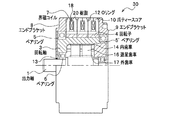
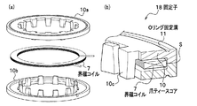
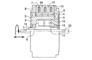
本発明の一実施形態である変速機構付回転電機について図1及び図2を参照して説明する。図1は、変速機構付回転電機である減速モータ30の断面図であり、図2は減速モータ30の固定子に使用される爪ティースコア10を示した斜視図である。
図1において、本実施形態の減速モータ30は、円環状の爪ティースコア10の内部に設けられた界磁コイル7からなる3個の固定子と、多極に磁化された円筒状の回転子4を表面に設けた回転軸3と、回転軸3の内部に設けられ、出力軸1の回転速度を減速する変速機構(後記)とを主要構成としている。
(First embodiment)
A rotating electrical machine with a speed change mechanism according to an embodiment of the present invention will be described with reference to FIGS. 1 and 2. FIG. 1 is a cross-sectional view of a
In FIG. 1, a
図2において、固定子18は、圧粉磁心などの軟磁性体で構成された円環状の2つの爪ティースコア10a,10bと、被覆導線が円環状に巻回された界磁コイル7を備え、2つの爪ティースコア10a,10bが界磁コイル7を装入できるように構成され、樹脂などの有機材料によって封止されている(図2(a)参照)。爪ティースコア10a,10bの断面はL字状に形成され、このL字の短辺側Sを重ね合わせることによりU字状に形成され、そのU字状の凹部に界磁コイル7が装入される。これにより、固定子18の断面は略長方形に形成される。また、爪ティースコア10a,10bの内周面には、台形状の複数の爪部(爪ティース)10cが離間して形成され、円形状のOリング固定溝11が側面に凹設されている(図2(b)参照)。なお、爪部10cの長さは固定子18の厚さに略等しく、固定子18の外径と内径との比率は5:3よりも内径が大きい。
In FIG. 2, the
再び、図1に戻り、3個の固定子18が軸方向に併設され、各界磁コイル7の端末は、固定子18の外周面から引き出され、その端末はY結線あるいはΔ結線されることにより、界磁コイル7に三相交流が印加されるようになっている。固定子18は樹脂20により封止され、固定子18を軸方向前後に挟み込むエンドブラケット8,9と固定子18との間は封止部材であるOリング12によって封止されている。また、各固定子18の間もOリング12によって封止されている。さらに、爪ティースコア10a,10bの内周面に設けられた複数の爪部に対向するように円筒状の回転子4を表面に備える回転軸3が設けられている。また、回転子4は、固定子18の爪磁極数と同数の極を有する磁石が回転軸3に円筒状に貼り付けられて構成されている。固定子18及び回転子4により爪ティースモータが構成される。
Returning to FIG. 1 again, three
また、回転軸3の内周面には内歯車14が形成されており、遊星歯車16を介して、回転子4に発生したトルクが外歯車17が形成された出力軸1に伝達される。なお、遊星歯車16は、90度毎の等角度方向に4個設けられており、遊星歯車16の軸は回転軸3に保持されている。また、回転軸3は、ベアリング5を用いてエンドブラケット8に回転可能に保持され、ベアリング5’を用いてエンドブラケット9に固定されている。また、出力軸1は、ベアリング6で回転軸3に回転可能に保持され、封止部材であるオイルシール13によりエンドブラケット8と封止されている。これにより、回転軸3の回転速度が減速されて、出力軸1に伝達される。また、内歯車14が形成された回転軸3、遊星歯車16、及び外歯車17が形成された出力軸1を備える変速機構は潤滑油で満たされている。
Further, an internal gear 14 is formed on the inner peripheral surface of the
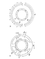
次に、図3を参照して、爪ティースモータの動作原理を説明する。
図3(a)に示されるように、爪ティースコア10aに設けられた爪部10cと爪ティースコア10bに設けられた爪部10dとは、内周面側に交互に配列され、空気あるいは潤滑油によるギャップが形成されている。
固定子18の界磁コイル7に正弦波交流電圧を印加すると、図3(b)に示されるような正弦波交流電流が流れる。この正弦波交流電流は、時刻T1のときに正の最大電流が流れ、時刻T2のときに負の最大電流が流れる。この電流により、右ねじの法則に従った方向の磁束が、爪ティースコア10aと爪ティースコア10bと爪部10c,10dの間に形成された磁気ギャップとからなる閉路に生成する。なお、太実線のように爪部10dから爪ティースコア10a,10bのコア部を介して爪部10cまで時計回りに流れる磁束の場合は、爪部10dがN極に磁化し、爪部10cがS極に磁化する(図3(a)にゴシック体で記載)。逆に、太破線のように爪部10cから爪ティースコア10a,10bのコア部を介して爪部10dまで反時計回りに流れる磁束の場合は、爪部10cがN極に磁化し、爪部10dがS極に磁化する(図3(a)に明朝体で記載)。
Next, the operation principle of the claw tooth motor will be described with reference to FIG.
As shown in FIG. 3 (a), the
When a sine wave AC voltage is applied to the
図3(c)は、界磁コイル7に流れる電流が反時計回りに流れたときの磁化の様子を示した図であり、爪ティースコア10a,10bに設けられた複数の爪部10c,10dに発生したS極と回転子4のN極とが引きつけ合い、爪部に発生したN極と回転子4のS極とが引きつけ合い、これにより回転子4が反時計回りに回転する。一方、図3(d)は、界磁コイル7に流れる電流が時計回りに流れたときの磁極の様子を示した図であり、爪ティースコア10a,10bに設けられた複数の爪部に発生したN極と回転子4のS極とが引きつけ合い、爪部に発生したS極と回転子4のN極とが引きつけ合い回転子4が時計回りに回転する。
FIG. 3C is a diagram showing a state of magnetization when the current flowing through the
変速機構付回転電機は、通常のモータ(回転電機)が得ることができる回転速度、トルク出力を向上することを目的としている。例えば、図1に示す減速モータ30から変速機構を除いた爪ティースモータの回転速度をN(rad/sec)とし、出力トルクをT(N・m)とすると、爪ティースモータ自体の機械的出力はN・T(W)である。これを本実施形態の減速モータ30の構造とし、モータ部分の回転速度を2倍として、減速比を2:1とすると出力軸端では、トルクは2倍の2Tとなるため、出力を2N・T(W)と2倍にすることができる。このとき、モータ部分に入力される電流は、モータ部分で発生するトルクが同一なので同じである。よって、同じ電流値、同じ外形のまま2倍の軸端出力をとることができる。これを達成するためには、モータ自体の回転速度を上昇する必要がある。
The rotating electrical machine with a speed change mechanism is intended to improve the rotational speed and torque output that can be obtained by a normal motor (rotating electrical machine). For example, assuming that the rotation speed of the claw teeth motor excluding the speed change mechanism from the
次に図4の12スロット8極のスロット型モータの断面構造図を用いて、比較例であるスロット型モータについて説明する。なお、図では上半分のみ記載されている。
外形がd1の固定子コアに上半分で6本、計12本のティース15aが設けられ、ティース間に巻線を巻回するスペースであるスロットが形成されている。すなわち、巻線がティースに巻回された複数の界磁コイルが円環状に形成されている。また、ティース15aの内周側に多極に磁化された回転子4が回転可能なように設けられている。このモータを5000r/minで回転させようとしたときの電機子電流(界磁電流)の基本周波数は、333Hzである。単純に前記の例のように回転速度を10000r/minと2倍にするとこの周波数は666Hzと2倍になる。通常、うず電流による鉄損は周波数の2乗に比例するため、周波数を上げることはスロット型モータの効率を著しく低下させてしまうので得策では無い。しかし、この周波数を下げるためには、極数を減らす方法がある。
Next, a slot type motor which is a comparative example will be described with reference to a cross-sectional structure diagram of a 12 slot 8-pole slot type motor shown in FIG. In the figure, only the upper half is shown.
A total of twelve
次に、図5を参照して、極数が相違する場合についてスロット型モータと爪ティースモータとを比較する。図5(a)はスロット型モータの原理を示す図であり、T字状の複数のティース15cが固定子外周部の内側に等角度に設けられ、ティース間にスロットが形成される。
複数のティース15cの内周側に回転子4が回転可能なように設けられている。ここでは特に、同図の上半分に記載されているようにティースを3本にした場合と、下半分に記載されているようにティースを1本にした場合とを各部の磁束密度を一定にしてコアの断面積に対応するコアの厚さを比較する。コイル巻線部を通過する磁束は固定子外周部で2分割されるので、3本のティースの各コイル巻線部の径をDとすれば、固定子外周部の厚さはD/2となる。一方、1本のティースのコイル巻線部の径は3D必要になり、固定子外周部の厚さは3D/2必要になる。従って、1本のティースの方が3本のティースの場合よりも固定子外周部の厚さが3倍必要になるので、モータの外径が同一であるときコイル巻線部のラジアル方向長が短縮し、コイルの量が減少する。また、ティースの重量も3倍になることから、ティースの先端部を太くし、付け根部分に向かって徐々に細くすることが好ましい。言い換えれば、コアバック部分のラジアル方向幅もそのティースの太さに応じて断面積を広げる必要がある。この場合には、ティースと固定子外周部との間に形成されたコイル巻線部分の空間が減少し、巻線の量が減少する。
Next, referring to FIG. 5, the slot type motor and the claw tooth motor are compared in the case where the number of poles is different. FIG. 5 (a) is a diagram showing the principle of the slot type motor. A plurality of T-shaped
The rotor 4 is rotatably provided on the inner peripheral side of the plurality of
言い換えれば、スロット部分には、元の3本のティースの場合と同量の巻線を施さなければならないため、モータの外径は大きくなる。すなわち、スロットに同量の巻線を巻くためには固定子の外径を大きくする必要がある。また、極数を少なくすることで、動作時のトルク脈動(トルクリップル)が大きくなるために、変速機構などにバックラッシュを有する本実施形態のモータには適していないということも言える。 In other words, since the same amount of winding as in the case of the original three teeth must be applied to the slot portion, the outer diameter of the motor becomes large. That is, in order to wind the same amount of winding in the slot, it is necessary to increase the outer diameter of the stator. It can also be said that reducing the number of poles increases torque pulsation (torque ripple) during operation, which is not suitable for the motor of this embodiment having a backlash in the transmission mechanism or the like.
次に図5(b)は爪ティースモータの原理を示す図であり、上半分に記載の4枚の爪ティースを設けた場合と、下半分に記載の1枚の爪ティースを設けた場合とを比較する。起磁力NIは一定であるので、磁束密度は回転子4に対向する部分の面積に依存し、4枚の爪ティースの各々の長さをLとしたとき、1枚の爪ティースを設けた場合は、長さが4Lになるのみであり、コイルの量、外径には影響しない。 Next, FIG. 5 (b) is a diagram showing the principle of the claw tooth motor, in which four claw teeth described in the upper half are provided, and in which one claw tooth described in the lower half is provided. Compare Since the magnetomotive force NI is constant, the magnetic flux density depends on the area of the portion facing the rotor 4, and when the length of each of the four claw teeth is L, one claw tooth is provided. Only has a length of 4L, and does not affect the amount and outer diameter of the coil.
すなわち、8極8爪タイプと、4極4爪タイプとでモータ径は変わらない。これは、一極ごとの磁束が増加する分、それに対する爪部分の断面積が、周方向で増加するためである。これによって、周波数を低くしながらも小形のモータを構成できるため、モータの外径が大きくならない。 That is, the motor diameter does not change between the 8-pole 8-claw type and the 4-pole 4-claw type. This is because the cross-sectional area of the claw portion corresponding to the increase in the magnetic flux for each pole increases in the circumferential direction. As a result, a small motor can be configured while reducing the frequency, so that the outer diameter of the motor does not increase.
また、モータが発生する回転力を変速機構で減速することで大きい出力軸でのトルクを得ることが可能となる。従来のスロット型モータ(特許文献2)で構成する場合に比べ、コイルエンド部分が無いために、軸方向に短く、扁平で大トルクが実現可能である。また、潤滑油が満たされる領域に界磁コイルが露出しないために、磨耗粉等による界磁コイルの絶縁損傷などの対策が不要であり、システム全体の外形を小さくすることができる。また、コアと界磁コイル、ブラケットとコアなどとの接触面積が大きく熱伝導性も向上できる。 Further, it is possible to obtain a large torque at the output shaft by decelerating the rotational force generated by the motor with the speed change mechanism. Compared to a conventional slot type motor (Patent Document 2), since there is no coil end portion, the axial direction is short, flat and large torque can be realized. In addition, since the field coil is not exposed in the region filled with the lubricating oil, it is not necessary to take measures such as insulation damage of the field coil due to wear powder or the like, and the overall outer shape of the system can be reduced. Further, the contact area between the core and the field coil, the bracket and the core is large, and the thermal conductivity can be improved.
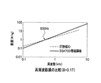
また、前記したトルク脈動の問題で周波数を上げたモータで対応する場合においても、爪ティースモータは、圧粉磁心で構成するために、有利となる。図6の周波数−鉄損特性に示すように、圧粉磁心(破線参照)は周波数0.1kHzにおいて0.2W/kgの鉄損であり、5kHzにおいて5W/kg程度まで対数グラフ上で直線的に増加し、50A700電磁鋼板(実線参照)は、0.1kHzにおいて0.1W/kgの鉄損であり、10kHzにおいて100W/kg程度まで対数グラフ上で直線的に増加し、500Hz程度で交差する。このため、
圧粉磁心は高周波になるほど、50A700電磁鋼板よりも鉄損(W/kg)を低くできる特性を有している。このため、高速化した場合においても効率をそれほど損なわずに構成する設計が可能となり、2倍程度の高速化においては、トルクリップルの問題をそれほど気にならない極数で構成することが可能である。
In addition, even when a motor with an increased frequency due to the problem of torque pulsation described above is used, the claw tooth motor is advantageous because it is composed of a dust core. As shown in the frequency-iron loss characteristics of FIG. 6, the dust core (see broken line) has an iron loss of 0.2 W / kg at a frequency of 0.1 kHz and is linear on a logarithmic graph up to about 5 W / kg at a frequency of 5 kHz. The 50A700 magnetic steel sheet (see solid line) has an iron loss of 0.1 W / kg at 0.1 kHz, increases linearly on the logarithmic graph to about 100 W / kg at 10 kHz, and crosses at about 500 Hz. . For this reason,
The dust core has a characteristic that the iron loss (W / kg) can be lowered as the frequency becomes higher than that of the 50A700 electromagnetic steel sheet. For this reason, even when the speed is increased, it is possible to design with less loss of efficiency, and at about twice the speed, it is possible to configure with the number of poles that does not matter much about the problem of torque ripple. .
以上説明したように、本実施形態によれば、モータとして必要な外径内で変速機構を回転子4の内周側部分に配置できるので外径同一で出力トルクの大きいモータを得ることが可能となる。また、潤滑油が界磁コイル7に触れる構造でないため、製品寿命が長く、信頼性のよい製品が実現できる。
As described above, according to the present embodiment, since the speed change mechanism can be arranged in the inner peripheral portion of the rotor 4 within the outer diameter necessary for the motor, it is possible to obtain a motor having the same outer diameter and a large output torque. It becomes. In addition, since the structure does not have a structure in which the lubricating oil touches the
(第2実施形態)
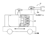
前記実施形態は、回転電機であるモータについて説明したが、このモータを使用した駆動装置として構成することができる。自動車機器あるいは図7のような移動ロボットとが駆動装置の例として考えられる。
図7に示す移動ロボット(自走ロボット)などの移動体の旋回する大トルクが必要なアームの関節部分などに利用することで、移動体の重量を軽くでき、移動体のバッテリ寿命の確保が可能となる。移動ロボット31には、車輪33を用いて前後方向に移動可能な本体部に減速モータ30が搭載されており、この減速モータ30が旋回アーム32aを水平方向に回転させ、旋回アーム32aに内蔵されている他の減速モータが旋回アーム33bを水平方向に回転させている。
(Second Embodiment)
Although the said embodiment demonstrated the motor which is a rotary electric machine, it can be comprised as a drive device using this motor. An automobile device or a mobile robot as shown in FIG.
The weight of the moving body can be reduced and the battery life of the moving body can be ensured by using it for the joint part of the arm that requires a large torque for turning of the moving body such as the mobile robot (self-running robot) shown in FIG. It becomes possible. The
また、自動車機器では、一台あたりに多数のモータが使用されているため、自動車の燃費向上が叫ばれるなかで、自動車全体の重量を減らすためには個々のモータの重量を低減することが課題となっており、このような個所への出力密度の大きいモータとして適用可能である。図8にはその応用例の一例を示す。中空構造を利用しやすいことは前に示したとおりであるが、この機構を内側部分に配置する例の1つとして、送りネジ機構を配置することも可能である。中空を有する回転軸3、又は出力軸の内側部分に送りネジ22を有することで大推力を発生可能な駆動装置を得ることができる。
In automobile equipment, a large number of motors are used per unit. Therefore, in order to reduce the overall weight of automobiles, it is necessary to reduce the weight of each motor in order to reduce the weight of the whole automobile. Therefore, it can be applied as a motor having a large output density to such a place. FIG. 8 shows an example of the application. As described above, it is easy to use the hollow structure, but as an example of disposing this mechanism in the inner portion, it is also possible to dispose a feed screw mechanism. A drive device capable of generating a large thrust can be obtained by having the
(変形例)
本発明は前記した実施形態に限定されるものではなく、例えば以下のような種々の変形が可能である。
(1)第1実施形態は、減速モータを構成したが、発電機とすることも可能である。この場合には、変速機構が出力軸1の回転速度を加速して、加速された回転速度が回転軸3及び回転子4に伝達されることになる。
(2)第1実施形態は、正弦波交流電圧を界磁コイル7に印加したが、矩形波交流電圧を印加することもできる。出力軸1が無負荷の場合には、直線的に増加し、あるいは減少する無負荷電流が界磁コイル7に流れる。また、出力軸1に機械的負荷ωT(ω:回転角速度、T:トルク)がかかると、負荷に対応した定常電流が無負荷電流に重畳する。
(3)第1実施形態は、三相交流電圧を印加するために固定子18を軸方向に3個併設したが、1個の固定子18を用いて単相交流電圧を印加することもできる。この場合には、三相交流電圧を印加するよりもトルクリップルが大きくなる。
(Modification)
The present invention is not limited to the embodiments described above, and various modifications such as the following are possible.
(1) Although 1st Embodiment comprised the reduction motor, it is also possible to set it as a generator. In this case, the speed change mechanism accelerates the rotation speed of the
(2) In the first embodiment, a sine wave AC voltage is applied to the
(3) In the first embodiment, three
1 出力軸
3 回転軸
4 回転子
5 ベアリング
6 ベアリング
7 界磁コイル
8,9 エンドブラケット(筐体)
10,10a,10b 爪ティースコア(コア)
10c,10d 爪部(爪ティース)
11 Oリング固定溝
12 Oリング(封止部材)
13 オイルシール(封止部材)
14 内歯車(変速機構)
15,15a,15b,15c ティース
16 遊星歯車(変速機構)
17 外歯車(変速機構)
18 固定子
20 樹脂
22 送りねじ
30 減速モータ
31 移動ロボット
32a,32b 旋回アーム
33 車輪
1
10, 10a, 10b Nail tea score (core)
10c, 10d Nail part (nail teeth)
11 O-ring fixing groove 12 O-ring (sealing member)
13 Oil seal (sealing member)
14 Internal gear (transmission mechanism)
15, 15a, 15b,
17 External gear (transmission mechanism)
18
Claims (8)
前記固定子は、円環状の前記界磁コイルと、前記円環状の界磁コイル及び有機材料が封入され、内周面に突起する複数の爪部が設けられた円環状のコアとを備えることを特徴とする変速機構付回転電機。 A stator having a field coil in an annular shape, a cylindrical rotor that rotates inside the stator, a speed change mechanism provided inside the cylindrical rotor, at least the rotor, and the speed change mechanism And a rotary electric machine with a speed change mechanism comprising a housing enclosing lubricating oil,
The stator includes an annular field coil, and an annular core in which the annular field coil and an organic material are enclosed and provided with a plurality of claw portions protruding on an inner peripheral surface. A rotary electric machine with a speed change mechanism.
前記外周面から前記界磁コイルの端末が引き出され、
前記回転子の中心軸及び前記側面と前記筐体とを各々封止する封止部材を設けたことを特徴とする請求項1に記載の変速機構付回転電機。 The stator includes the inner peripheral surface, the outer peripheral surface, and two side surfaces, and has a substantially rectangular cross section;
The terminal of the field coil is pulled out from the outer peripheral surface,
2. The rotating electrical machine with a speed change mechanism according to claim 1, further comprising: a sealing member that seals the central axis and the side surface of the rotor and the casing.
Priority Applications (4)
| Application Number | Priority Date | Filing Date | Title |
|---|---|---|---|
| JP2006000589A JP2007185021A (en) | 2006-01-05 | 2006-01-05 | Dynamo-electric machine with speed change mechanism, and drive unit using it |
| CNA2006101721402A CN1996718A (en) | 2006-01-05 | 2006-12-29 | A rotating electrical machine with a transmission and a driving apparatus using the same |
| EP07000115A EP1806825A3 (en) | 2006-01-05 | 2007-01-04 | A rotating electrical machine with a transmission and a driving apparatus using the same |
| US11/620,112 US20070152522A1 (en) | 2006-01-05 | 2007-01-05 | Rotating Electrical Machine with a Transmission and a Driving Apparatus Using the Same |
Applications Claiming Priority (1)
| Application Number | Priority Date | Filing Date | Title |
|---|---|---|---|
| JP2006000589A JP2007185021A (en) | 2006-01-05 | 2006-01-05 | Dynamo-electric machine with speed change mechanism, and drive unit using it |
Publications (1)
| Publication Number | Publication Date |
|---|---|
| JP2007185021A true JP2007185021A (en) | 2007-07-19 |
Family
ID=37888106
Family Applications (1)
| Application Number | Title | Priority Date | Filing Date |
|---|---|---|---|
| JP2006000589A Pending JP2007185021A (en) | 2006-01-05 | 2006-01-05 | Dynamo-electric machine with speed change mechanism, and drive unit using it |
Country Status (4)
| Country | Link |
|---|---|
| US (1) | US20070152522A1 (en) |
| EP (1) | EP1806825A3 (en) |
| JP (1) | JP2007185021A (en) |
| CN (1) | CN1996718A (en) |
Cited By (3)
| Publication number | Priority date | Publication date | Assignee | Title |
|---|---|---|---|---|
| JP2014060876A (en) * | 2012-09-18 | 2014-04-03 | Toshiba Corp | Traverse magnetic-flux type motor |
| JP2015133910A (en) * | 2015-04-27 | 2015-07-23 | 株式会社東芝 | transverse flux motor |
| JP2015527046A (en) * | 2012-08-31 | 2015-09-10 | リーンテック モーター ゲゼルシャフト ミット ベシュレンクテル ハフツング ウント コンパニー コマンディートゲゼルシャフトLEANTEC Motor GmbH & Co. KG | Electromechanical transducer |
Families Citing this family (8)
| Publication number | Priority date | Publication date | Assignee | Title |
|---|---|---|---|---|
| DE102008007565A1 (en) * | 2008-02-05 | 2009-08-06 | BSH Bosch und Siemens Hausgeräte GmbH | Permanent magnet excited electric machine for driving a component of a household appliance and domestic appliance with such a machine |
| IT1394934B1 (en) * | 2009-04-23 | 2012-07-27 | Castellano | NEW TYPE OF STEP-BY-STEP OR STEPPER POSITIONER |
| FR2961037B1 (en) | 2010-04-28 | 2018-05-25 | Sintertech | REALIZATION OF A PHASE OF ROTATING HOMOPOLAR MACHINE APPLIED TO THE DESIGN OF ITS MAGNETIC CIRCUIT |
| TWI443258B (en) | 2011-10-12 | 2014-07-01 | Ind Tech Res Inst | Rotation device |
| EP2626982A1 (en) * | 2012-02-07 | 2013-08-14 | Siemens Aktiengesellschaft | Gear motor |
| JP6148085B2 (en) * | 2012-07-31 | 2017-06-14 | アスモ株式会社 | Motor, and stay core of motor and method of manufacturing rotor core |
| US10411528B2 (en) * | 2015-10-22 | 2019-09-10 | Samsung Electronics Co., Ltd. | Motor and motor control circuit |
| EP4208933A1 (en) * | 2020-09-02 | 2023-07-12 | Tolomatic, Inc. | Linear actuator system with integrated transverse flux motor |
Citations (4)
| Publication number | Priority date | Publication date | Assignee | Title |
|---|---|---|---|---|
| JPH02240901A (en) * | 1989-03-15 | 1990-09-25 | Toshiba Corp | Coil insulation of electric apparatus |
| JP2003143805A (en) * | 2001-11-06 | 2003-05-16 | Hitachi Ltd | Dynamoelectric machine |
| JP2005051970A (en) * | 2003-07-31 | 2005-02-24 | Japan Servo Co Ltd | Permanent magnet type stepping motor with speed reducer |
| JP2005168123A (en) * | 2003-12-01 | 2005-06-23 | Honda Motor Co Ltd | Structure for leading out winding of claw-pole motor |
Family Cites Families (17)
| Publication number | Priority date | Publication date | Assignee | Title |
|---|---|---|---|---|
| US3383534A (en) * | 1965-04-05 | 1968-05-14 | Rotron Mfg Co | Stator for electric motors |
| US3668585A (en) * | 1971-03-01 | 1972-06-06 | Kelsey Hayes Co | Electromagnetic device with cast magnetic path |
| FR2468798A1 (en) * | 1979-09-11 | 1981-05-08 | Tech Integrale | DEBRAYABLE MECHANISM, SCREW AND BEARING NUT |
| JP2607889B2 (en) * | 1987-08-04 | 1997-05-07 | 光洋精工株式会社 | Reduction motor |
| JP2581261B2 (en) * | 1990-04-27 | 1997-02-12 | ブラザー工業株式会社 | Step motor |
| JPH05308768A (en) * | 1992-04-28 | 1993-11-19 | Minebea Co Ltd | Stator yoke for stepping motor |
| US6098479A (en) * | 1997-08-23 | 2000-08-08 | Hoermansdoerfer; Gerd | Linear actuator and preferred application |
| US5986379A (en) * | 1996-12-05 | 1999-11-16 | General Electric Company | Motor with external rotor |
| DE10014226A1 (en) * | 2000-03-22 | 2001-09-27 | Bosch Gmbh Robert | Electromechanical wheel brake has transversal flux motor with annular stimulation winding enclosing axis, yokes distributed peripherally on stimulation winding, matching movable poles |
| EP1156576A1 (en) * | 2000-05-19 | 2001-11-21 | Société industrielle de Sonceboz S.A. | Rotary or linear actuator |
| DE60134928D1 (en) * | 2000-07-28 | 2008-09-04 | Japan Servo | Motor-driven system with toothed stator poles |
| AU2001289191A1 (en) * | 2000-09-06 | 2002-03-22 | Robert W. Ward | Stator core design |
| DE10305547A1 (en) * | 2002-02-08 | 2003-11-20 | Continental Teves Ag & Co Ohg | Stator module for brushless D.C. electric motor drive, e.g. for electromechanical wheel brake, has sprung contact between coil leads, and coils provided by attaching control unit or terminal to stator housing |
| US20040095037A1 (en) * | 2002-03-22 | 2004-05-20 | Albert Palmero | Low profile motor with internal gear train |
| DE10245663A1 (en) * | 2002-09-30 | 2004-04-08 | Robert Bosch Gmbh | Symmetrical drive for wiper components |
| JP4482918B2 (en) * | 2003-10-26 | 2010-06-16 | 義光 大川 | Permanent magnet type electric motor having ring-shaped stator coil |
| JP4303162B2 (en) * | 2004-05-25 | 2009-07-29 | ミネベア株式会社 | Actuator |
-
2006
- 2006-01-05 JP JP2006000589A patent/JP2007185021A/en active Pending
- 2006-12-29 CN CNA2006101721402A patent/CN1996718A/en active Pending
-
2007
- 2007-01-04 EP EP07000115A patent/EP1806825A3/en not_active Withdrawn
- 2007-01-05 US US11/620,112 patent/US20070152522A1/en not_active Abandoned
Patent Citations (4)
| Publication number | Priority date | Publication date | Assignee | Title |
|---|---|---|---|---|
| JPH02240901A (en) * | 1989-03-15 | 1990-09-25 | Toshiba Corp | Coil insulation of electric apparatus |
| JP2003143805A (en) * | 2001-11-06 | 2003-05-16 | Hitachi Ltd | Dynamoelectric machine |
| JP2005051970A (en) * | 2003-07-31 | 2005-02-24 | Japan Servo Co Ltd | Permanent magnet type stepping motor with speed reducer |
| JP2005168123A (en) * | 2003-12-01 | 2005-06-23 | Honda Motor Co Ltd | Structure for leading out winding of claw-pole motor |
Cited By (3)
| Publication number | Priority date | Publication date | Assignee | Title |
|---|---|---|---|---|
| JP2015527046A (en) * | 2012-08-31 | 2015-09-10 | リーンテック モーター ゲゼルシャフト ミット ベシュレンクテル ハフツング ウント コンパニー コマンディートゲゼルシャフトLEANTEC Motor GmbH & Co. KG | Electromechanical transducer |
| JP2014060876A (en) * | 2012-09-18 | 2014-04-03 | Toshiba Corp | Traverse magnetic-flux type motor |
| JP2015133910A (en) * | 2015-04-27 | 2015-07-23 | 株式会社東芝 | transverse flux motor |
Also Published As
| Publication number | Publication date |
|---|---|
| EP1806825A3 (en) | 2011-05-18 |
| CN1996718A (en) | 2007-07-11 |
| EP1806825A2 (en) | 2007-07-11 |
| US20070152522A1 (en) | 2007-07-05 |
Similar Documents
| Publication | Publication Date | Title |
|---|---|---|
| JP2007185021A (en) | Dynamo-electric machine with speed change mechanism, and drive unit using it | |
| JP5204094B2 (en) | Electric machine | |
| JP5539191B2 (en) | Magnetic inductor type rotating machine and fluid transfer device using the same | |
| US9071118B2 (en) | Axial motor | |
| JP5621794B2 (en) | Magnetic modulation type multi-axis motor | |
| JP2008043138A (en) | Auxiliary driving gear | |
| JP2007252174A (en) | Geared motor and planetary geared dynamo | |
| JP5688684B2 (en) | Rotating electric machine | |
| JP4212982B2 (en) | Rotating electric machine | |
| JP2008289244A (en) | Cooling structure of rotary electric machine | |
| JP4751134B2 (en) | Inductor type motor and vehicle equipped with the same | |
| JP2010516224A (en) | Multi-phase drive or generator machine | |
| JP4525026B2 (en) | Rotating electric machine | |
| JP2005348512A (en) | Dynamo-electric machine | |
| JP4525025B2 (en) | Rotating electric machine | |
| JP4446095B2 (en) | Rotation transmission device, power generation device and moving device | |
| FI130272B (en) | An electromechanical device | |
| JP2002315259A (en) | Engine generator | |
| CN211089426U (en) | Permanent magnet linear stepping motor | |
| JP2008118839A (en) | Motor | |
| JP2007089365A (en) | Wind turbine generator | |
| JP2013021875A (en) | Rotary electric machine | |
| JP2019039472A (en) | Driving device | |
| JP2021013204A (en) | Motor with reduction gear | |
| KR20200014040A (en) | Motor of motch structure for torque ripple |
Legal Events
| Date | Code | Title | Description |
|---|---|---|---|
| A621 | Written request for application examination |
Free format text: JAPANESE INTERMEDIATE CODE: A621 Effective date: 20081105 |
|
| A977 | Report on retrieval |
Free format text: JAPANESE INTERMEDIATE CODE: A971007 Effective date: 20110221 |
|
| A131 | Notification of reasons for refusal |
Free format text: JAPANESE INTERMEDIATE CODE: A131 Effective date: 20110301 |
|
| A02 | Decision of refusal |
Free format text: JAPANESE INTERMEDIATE CODE: A02 Effective date: 20111018 |