EP1402145B2 - Automatisches bohrsystem mit elektronik ausserhalb einer nicht-rotierenden hülse - Google Patents
Automatisches bohrsystem mit elektronik ausserhalb einer nicht-rotierenden hülse Download PDFInfo
- Publication number
- EP1402145B2 EP1402145B2 EP03726883A EP03726883A EP1402145B2 EP 1402145 B2 EP1402145 B2 EP 1402145B2 EP 03726883 A EP03726883 A EP 03726883A EP 03726883 A EP03726883 A EP 03726883A EP 1402145 B2 EP1402145 B2 EP 1402145B2
- Authority
- EP
- European Patent Office
- Prior art keywords
- drilling
- force application
- drilling assembly
- application members
- assembly
- Prior art date
- Legal status (The legal status is an assumption and is not a legal conclusion. Google has not performed a legal analysis and makes no representation as to the accuracy of the status listed.)
- Expired - Lifetime
Links
Images


Classifications
-
- E—FIXED CONSTRUCTIONS
- E21—EARTH OR ROCK DRILLING; MINING
- E21B—EARTH OR ROCK DRILLING; OBTAINING OIL, GAS, WATER, SOLUBLE OR MELTABLE MATERIALS OR A SLURRY OF MINERALS FROM WELLS
- E21B44/00—Automatic control systems specially adapted for drilling operations, i.e. self-operating systems which function to carry out or modify a drilling operation without intervention of a human operator, e.g. computer-controlled drilling systems; Systems specially adapted for monitoring a plurality of drilling variables or conditions
- E21B44/005—Below-ground automatic control systems
-
- E—FIXED CONSTRUCTIONS
- E21—EARTH OR ROCK DRILLING; MINING
- E21B—EARTH OR ROCK DRILLING; OBTAINING OIL, GAS, WATER, SOLUBLE OR MELTABLE MATERIALS OR A SLURRY OF MINERALS FROM WELLS
- E21B7/00—Special methods or apparatus for drilling
- E21B7/04—Directional drilling
- E21B7/06—Deflecting the direction of boreholes
- E21B7/062—Deflecting the direction of boreholes the tool shaft rotating inside a non-rotating guide travelling with the shaft
-
- E—FIXED CONSTRUCTIONS
- E21—EARTH OR ROCK DRILLING; MINING
- E21B—EARTH OR ROCK DRILLING; OBTAINING OIL, GAS, WATER, SOLUBLE OR MELTABLE MATERIALS OR A SLURRY OF MINERALS FROM WELLS
- E21B7/00—Special methods or apparatus for drilling
- E21B7/04—Directional drilling
- E21B7/06—Deflecting the direction of boreholes
- E21B7/068—Deflecting the direction of boreholes drilled by a down-hole drilling motor
Definitions
- the drill bit is steered along a desired trajectory by the force application members that, either in unison or independently, apply a force on the wall of the wellbore.
- the non-rotating sleeve is usually disposed in a wheel-like fashion around a bearing assembly housing associated with the drilling motor.
- These force application members that expand radially when energized by a power source such as an electrical device (e.g. , electric motor) or a hydraulic device (e.g. , hydraulic pump).
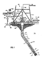
- the surface control unit 40 displays desired drilling parameters and other information on a display/monitor 44 that is utilized by an operator to control the drilling operations.
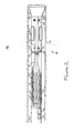
- the BHA processor 42 may be positioned close to the steering assembly 200 (as shown in Figure 3 ) or positioned in a different section of the BHA 100 (as shown in Figure 2 ).
- Each processor 40,42 contains a computer, memory for storing data, recorder for recording data and other known peripherals.
- the drilling assembly 100 includes the drill string 20, a drilling motor 120, a steering assembly 200, the BHA processor 42, and the drill bit 50.
- the bearing assembly 124 may alternatively be a device that is operationally and/or structurally independent of the drilling motor 120.
- the present invention is not limited to any particular bearing configuration. For example, there is no particular minimum or maximum number of radial or thrust bearings that must be present in order to advantageously apply the teachings of the present invention.
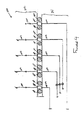
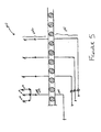
- BHA sensors S 1 can be dispersed throughout the length of the BHA 100.
- the above-described sensors generates signals representative of its corresponding parameter of interest, which signals are transmitted to a processor by hard wire, magnetic or acoustic coupling.
- the sensors generally described above are known in the art and therefore are not described in detail herein.
Landscapes
- Life Sciences & Earth Sciences (AREA)
- Engineering & Computer Science (AREA)
- Geology (AREA)
- Mining & Mineral Resources (AREA)
- Physics & Mathematics (AREA)
- Environmental & Geological Engineering (AREA)
- Fluid Mechanics (AREA)
- General Life Sciences & Earth Sciences (AREA)
- Geochemistry & Mineralogy (AREA)
- Earth Drilling (AREA)
- Ultra Sonic Daignosis Equipment (AREA)
Claims (31)
- Bohrvorrichtung mit einer Bohrkrone (50) zum Bohren eines Bohrloches
mit einem rotierenden, mit der Bohrkrone gekuppelten Glied (130, 20, 22, 102),
mit einer nicht rotierenden Hülse (220), die einen Teil des rotierenden Gliedes an ausgewählter Stelle umgibt, wobei die Hülse mit einer Mehrzahl von Kraftstützelementen (250) versehen ist, von denen jedes sich bei Zuführung von Antriebsleistung radial nach außen bewegt, um an einer Wand des Bohrloches anzugreifen, und
mit einer in dem rotierenden Glied angeordneten hydraulischen Antriebsquelle (230) zum Antreiben der Kraftstützelemente, gekennzeichnet durch Zuführen von Fluid unter Druck an die Kraftstützelemente. - Bohrvorrichtung nach Anspruch 1, weiter gekennzeichnet durch einen Prozessor (42) zum Regeln(i) der Kraft, die durch die Kraftstützelemente (250) gegen die Wand des Bohrloches ausgeübt wird oder(ii) der Position der Kraftstützelemente oder(iii) der Bewegung der Kraftstützelemente.
- Bohrvorrichtung nach Anspruch 2, dadurch gekennzeichnet, dass der Prozessor (42) die Kraftstützelemente (250) abhängig von Messwerten mindestens eines Sensors regelt, welcher Sensor dazu ausgebildet ist,(a) die Ausrichtung der Bohrvorrichtung oder(b) einen Parameter, der bezüglich der Formation von Interesse ist, oder(c) einen interessierenden Parameter bezüglich der Bohrvorrichtung festzustellen.
- Bohrvorrichtung nach Anspruch 2 oder 3, dadurch gekennzeichnet, dass der Prozessor (42) zum Steuern der Bohrvorrichtung in einer geschlossenen Regelschleife programmiert ist.
- Bohrvorrichtung nach Anspruch 1, weiter gekennzeichnet durch eine Oberflächenregeleinheit (40) und einen unten im Bohrloch angeordneten Prozessor (42), die beide zusammenarbeiten, um die Bohrvorrichtung entlang einer ausgewählten Bahn des Bohrlochs zu steuern.
- Bohrvorrichtung nach einem oder mehreren der vorstehenden Ansprüche, weiter gekennzeichnet durch eine Elektronik zum Steuern der den Kraftstützelementen (250) durch die Antriebsquelle (230) zugeführten Antriebsleistung, wobei die Elektronik außerhalb der nicht rotierenden Hülse (220) angeordnet ist.
- Bohrvorrichtung nach Anspruch 6, dadurch gekennzeichnet, dass die Elektronik in einem entfernbaren Modul außerhalb der nicht rotierenden Hülse (220) isoliert angeordnet ist.
- Bohrvorrichtung nach Anspruch 2, dadurch gekennzeichnet, dass der Prozessor (42) mit der Antriebsquelle (230) gekoppelt und so konfiguriert ist, dass er einen Zustand der Kraftstützelemente (250) durch Überwachung der Antriebsquelle bestimmt.
- Bohrvorrichtung nach einem oder mehreren der vorstehenden Ansprüche, dadurch gekennzeichnet, dass die Kraftstützelemente (250) durch Hydraulikfluid betätigt werden und dass die Antriebsquelle eine Pumpe enthält, die zum wahlweisen Zuführen von Hydraulikfluid an die Kraftstützelemente ausgebildet ist.
- Bohrvorrichtung nach Anspruch 9, weiter gekennzeichnet durch einen Hydraulikkreis (240), der zum Befördern von Hydraulikfluid zwischen der Pumpe und den Kraftstützelementen (250) ausgebildet ist.
- Bohrvorrichtung nach Anspruch 10, dadurch gekennzeichnet, dass der Hydraulikkreis (240) mindestens ein Ventil (246) und mindestens ein zugeordnetes Ventilbetätigungsglied (246) enthält, die dazu ausgebildet sind,(i) den Fluß oder(ii) den Druckdes Hydraulikfluid zu steuern.
- Bohrvorrichtung nach Anspruch 11, dadurch gekennzeichnet, dass das Ventil (246) und das Ventilbetätigungsglied (246)(i) durch das Tastverhältnis oder(ii) durch Proportionalhydraulikgesteuert werden.
- Bohrvorrichtung nach Anspruch 11, dadurch gekennzeichnet, dass der Hydraulikkreis (240) außerdem mindestens eine hydraulische Drehkupplung zum Weiterleiten von Hydraulikfluid zwischen dem Gehäuse und der Hülse enthält.
- Bohrvorrichtung nach einem oder mehreren der Ansprüche 9 bis 13, dadurch gekennzeichnet, dass die Antriebsquelle (230) für jedes der Kraftstützelemente (250) eine Pumpe aufweist.
- Bohrvorrichtung nach einem oder mehreren der vorstehenden Ansprüche, weiter gekennzeichnet durch einen Bohrmotor (120) zum Antreiben der Bohrkrone (50), wobei das rotierende Glied (130, 20, 22, 102) ein dem Bohrmotor zugeordnetes Lagergehäuse (130) aufweist.
- Verfahren zum Bohren eines Bohrloches mit den Verfahrensschritten:Kuppeln eines rotierenden Gliedes (130, 20, 22, 102) mit einer Bohrkrone (50), um eine Bohrvorrichtung zum Bohren eines Bohrloches zu bilden,Umgeben eines Teils des rotierenden Gliedes mit einer nicht rotierenden Hülse (220), die eine Mehrzahl von Kraftstützelementen (250) aufweist, von denen jedes sich bei Zuführung einer Antriebsleistung radial nach außen erstreckt, um an einer Wand des Bohrloches anzugreifen,Einsetzen der Bohrvorrichtung in ein Bohrloch, undAntreiben der Kraftstützelemente mit einer hydraulischen Antriebsquelle (230), die in dem rotierenden Glied angeordnet ist, wobei die Antriebsquelle Fluid unter Druck an die Kraftstützelemente zuführt.
- Verfahren nach Anspruch 16, weiter gekennzeichnet durch Anordnen einer Elektronik zum Steuern des Antriebs der Kraftstützelemente außerhalb der nicht rotierenden Hülse.
- Verfahren nach Anspruch 17, gekennzeichnet durch isoliertes Anordnen der der Bohrvorrichtung zugeordneten Elektronik in einem entfernbaren Modul.
- Verfahren nach Anspruch 16, 17 oder 18, weiter gekennzeichnet durch das Regeln der Kraftstützelemente mit einem Prozessor (42), um die Bohrkrone in einer ausgewählten Richtung zu lenken.
- Verfahren nach einem oder mehreren der Ansprüche 16 bis 19, weiter gekennzeichnet durch folgende Verfahrensschritte:(a) Bestimmen der Richtung der Bohrvorrichtung,(b) Vergleichen der Position der Bohrvorrichtung mit einem gewünschten Bohrlochprofil oder einem Zielort einer Information, und(c) Ausgabe von Korrekturbefehlen, mit denen mindestens ein Kraftzuführglied repositioniert wird, um den Bohrkopf in die gewünschte Richtung zu lenken.
- Verfahren nach einem oder mehreren der Ansprüche 16 bis 20, dadurch gekennzeichnet, dass ein interessierender Parameter festgestellt wird und dass die Bohrvorrichtung abhängig von dem interessierenden Parameter in eine ausgewählte Richtung gelenkt wird.
- Verfahren nach Anspruch 21, dadurch gekennzeichnet, dass die Antriebsquelle (230) eine Pumpe ist und dass die Pumpe mit einem Tastverhältnis betrieben wird.
- Bohrsystem zur Bildung eines Bohrloches in einer unterirdischen Formation mit einer Bohrvorrichtung nach Anspruch 1, weiter mit(a) einem an einem Ort an der Oberfläche aufgestellten Bohrturm (11),(b) einem durch den Bohrturm innerhalb des Bohrloches aufgehängten Bohrgestänge (20),(c) einer Schlammquelle zum Liefern von Bohrfluid über das Bohrgestänge,wobei die Bohrvorrichtung mit einem Ende des Bohrgestänges gekuppelt ist.
- Bohrsystem nach Anspruch 23, dadurch gekennzeichnet, dass die Kraftstützelemente (250) durch unter Druck gesetztes Hydraulikfluid einer Antriebsquelle (230) betätigt werden.
- Bohrsystem nach Anspruch 23, weiter gekennzeichnet durch mindestens ein erstes Element auf der nicht rotierenden Hülse (220) und mindestens ein zweites Element auf dem Gehäuse, wobei das erste und das zweite Element kooperieren und damit eine Anzeige der Richtung der Kraftstützelemente (250) ermöglichen.
- Bohrsystem nach Anspruch 25, dadurch gekennzeichnet, dass das erste Element einen Magneten und das zweite Element einen Magnetsensor enthält.
- Bohrsystem nach einem oder mehreren der Ansprüche 23 bis 26, dadurch gekennzeichnet, dass ein Telemetriesystem (39) vorgesehen ist, um eine Zweiweg-Telemetrieverbindung zwischen der Bohrvorrichtung und einem Ort an der Oberfläche zu bilden.
- Bohrsystem nach einem oder mehreren der Ansprüche 23 bis 27, dadurch gekennzeichnet, dass mindestens ein unten im Bohrloch angeordneter Sensor vorgesehen ist, der dazu ausgebildet ist, einen der folgenden Parameter festzustellen:(a) auf die Formation bezogene Parameter,(b) Eigenschaften des Bohrfluids,(c) Bohrparameter,(d) Zustände der Bohrvorrichtung,(e) Richtung der nicht rotierenden Hülse oder(f) Richtung der Lenkanordnung.
- Bohrsystem nach einem oder mehreren der Ansprüche 23 bis 28, dadurch gekennzeichnet, dass ein Prozessor (42) vorgesehen und dazu ausgebildet ist, die Bohrvorrichtung in eine ausgewählte Richtung zu lenken.
- Bohrsystem nach einem oder mehreren der Ansprüche 23 bis 28, weiter gekennzeichnet durch eine Oberflächenregeleinheit (40) und einen in der Nähe des Gehäuses angeordneten Prozessor (42), wobei die Oberflächenregeleinheit und der Prozessor kooperieren, um die Bohrvorrichtung entlang einer ausgewählten Bahn des Bohrloches zu lenken.
- Bohrsystem nach einem oder mehreren der Ansprüche 23 bis 30, weiter gekennzeichnet durch einen Bohrmotor (120) zum Antreiben der Bohrkrone (50), welcher Bohrmotor durch das Bohrfluid angetrieben wird.
Applications Claiming Priority (3)
| Application Number | Priority Date | Filing Date | Title |
|---|---|---|---|
| US38064602P | 2002-05-15 | 2002-05-15 | |
| US380646P | 2002-05-15 | ||
| PCT/US2003/015332 WO2003097989A1 (en) | 2002-05-15 | 2003-05-15 | Closed loop drilling assembly with electronics outside a non-rotating sleeve |
Publications (3)
| Publication Number | Publication Date |
|---|---|
| EP1402145A1 EP1402145A1 (de) | 2004-03-31 |
| EP1402145B1 EP1402145B1 (de) | 2006-07-26 |
| EP1402145B2 true EP1402145B2 (de) | 2010-03-17 |
Family
ID=29549995
Family Applications (1)
| Application Number | Title | Priority Date | Filing Date |
|---|---|---|---|
| EP03726883A Expired - Lifetime EP1402145B2 (de) | 2002-05-15 | 2003-05-15 | Automatisches bohrsystem mit elektronik ausserhalb einer nicht-rotierenden hülse |
Country Status (7)
| Country | Link |
|---|---|
| US (1) | US6913095B2 (de) |
| EP (1) | EP1402145B2 (de) |
| AU (1) | AU2003229296A1 (de) |
| CA (1) | CA2453774C (de) |
| DE (1) | DE60307007T3 (de) |
| NO (1) | NO324447B1 (de) |
| WO (1) | WO2003097989A1 (de) |
Cited By (2)
| Publication number | Priority date | Publication date | Assignee | Title |
|---|---|---|---|---|
| CN104989370A (zh) * | 2015-07-13 | 2015-10-21 | 中国海洋石油总公司 | 一种滑动导向钻井闭环控制系统及其控制方法 |
| CN105041210A (zh) * | 2015-07-13 | 2015-11-11 | 中国海洋石油总公司 | 基于滑动导向钻井闭环控制的钻机系统及钻井方法 |
Families Citing this family (88)
| Publication number | Priority date | Publication date | Assignee | Title |
|---|---|---|---|---|
| US9051781B2 (en) | 2009-08-13 | 2015-06-09 | Smart Drilling And Completion, Inc. | Mud motor assembly |
| US9745799B2 (en) | 2001-08-19 | 2017-08-29 | Smart Drilling And Completion, Inc. | Mud motor assembly |
| US7556105B2 (en) * | 2002-05-15 | 2009-07-07 | Baker Hughes Incorporated | Closed loop drilling assembly with electronics outside a non-rotating sleeve |
| US6761232B2 (en) | 2002-11-11 | 2004-07-13 | Pathfinder Energy Services, Inc. | Sprung member and actuator for downhole tools |
| GB2415972A (en) * | 2004-07-09 | 2006-01-11 | Halliburton Energy Serv Inc | Closed loop steerable drilling tool |
| US7168510B2 (en) * | 2004-10-27 | 2007-01-30 | Schlumberger Technology Corporation | Electrical transmission apparatus through rotating tubular members |
| US7708086B2 (en) * | 2004-11-19 | 2010-05-04 | Baker Hughes Incorporated | Modular drilling apparatus with power and/or data transmission |
| GB2422388B (en) * | 2005-01-20 | 2010-05-12 | Schlumberger Holdings | Bi-directional rotary steerable system actuator assembly and method |
| US7204325B2 (en) | 2005-02-18 | 2007-04-17 | Pathfinder Energy Services, Inc. | Spring mechanism for downhole steering tool blades |
| US7389830B2 (en) * | 2005-04-29 | 2008-06-24 | Aps Technology, Inc. | Rotary steerable motor system for underground drilling |
| US7383897B2 (en) | 2005-06-17 | 2008-06-10 | Pathfinder Energy Services, Inc. | Downhole steering tool having a non-rotating bendable section |
| US8522897B2 (en) | 2005-11-21 | 2013-09-03 | Schlumberger Technology Corporation | Lead the bit rotary steerable tool |
| US8528664B2 (en) | 2005-11-21 | 2013-09-10 | Schlumberger Technology Corporation | Downhole mechanism |
| US8297378B2 (en) | 2005-11-21 | 2012-10-30 | Schlumberger Technology Corporation | Turbine driven hammer that oscillates at a constant frequency |
| US8297375B2 (en) | 2005-11-21 | 2012-10-30 | Schlumberger Technology Corporation | Downhole turbine |
| US8225883B2 (en) | 2005-11-21 | 2012-07-24 | Schlumberger Technology Corporation | Downhole percussive tool with alternating pressure differentials |
| US7571780B2 (en) | 2006-03-24 | 2009-08-11 | Hall David R | Jack element for a drill bit |
| US8360174B2 (en) | 2006-03-23 | 2013-01-29 | Schlumberger Technology Corporation | Lead the bit rotary steerable tool |
| US8316964B2 (en) | 2006-03-23 | 2012-11-27 | Schlumberger Technology Corporation | Drill bit transducer device |
| US8408336B2 (en) | 2005-11-21 | 2013-04-02 | Schlumberger Technology Corporation | Flow guide actuation |
| WO2007104636A1 (en) * | 2006-03-10 | 2007-09-20 | Novo Nordisk A/S | An injection device and a method of changing a cartridge in the device |
| US8011457B2 (en) * | 2006-03-23 | 2011-09-06 | Schlumberger Technology Corporation | Downhole hammer assembly |
| BRPI0709363A2 (pt) | 2006-03-24 | 2011-07-12 | David R Hall | conjunto de broca de perfuração, método de recuperação de dados furo - abaixo e cabo de ferramentaria |
| US7413034B2 (en) * | 2006-04-07 | 2008-08-19 | Halliburton Energy Services, Inc. | Steering tool |
| WO2008004999A1 (en) * | 2006-06-30 | 2008-01-10 | Baker Hughes Incorporated | Closed loop drilling assembly with electronics outside a non-rotating sleeve |
| US8528636B2 (en) | 2006-09-13 | 2013-09-10 | Baker Hughes Incorporated | Instantaneous measurement of drillstring orientation |
| US8118114B2 (en) | 2006-11-09 | 2012-02-21 | Smith International Inc. | Closed-loop control of rotary steerable blades |
| US7967081B2 (en) | 2006-11-09 | 2011-06-28 | Smith International, Inc. | Closed-loop physical caliper measurements and directional drilling method |
| US7464770B2 (en) * | 2006-11-09 | 2008-12-16 | Pathfinder Energy Services, Inc. | Closed-loop control of hydraulic pressure in a downhole steering tool |
| US7814988B2 (en) * | 2007-01-10 | 2010-10-19 | Baker Hughes Incorporated | System and method for determining the rotational alignment of drillstring elements |
| US8395388B2 (en) * | 2007-02-19 | 2013-03-12 | Schlumberger Technology Corporation | Circumferentially spaced magnetic field generating devices |
| US8436618B2 (en) * | 2007-02-19 | 2013-05-07 | Schlumberger Technology Corporation | Magnetic field deflector in an induction resistivity tool |
| US7598742B2 (en) * | 2007-04-27 | 2009-10-06 | Snyder Jr Harold L | Externally guided and directed field induction resistivity tool |
| US7265649B1 (en) | 2007-02-19 | 2007-09-04 | Hall David R | Flexible inductive resistivity device |
| US7994791B2 (en) * | 2007-02-19 | 2011-08-09 | Schlumberger Technology Corporation | Resistivity receiver spacing |
| US8198898B2 (en) * | 2007-02-19 | 2012-06-12 | Schlumberger Technology Corporation | Downhole removable cage with circumferentially disposed instruments |
| US7377333B1 (en) | 2007-03-07 | 2008-05-27 | Pathfinder Energy Services, Inc. | Linear position sensor for downhole tools and method of use |
| US8497685B2 (en) | 2007-05-22 | 2013-07-30 | Schlumberger Technology Corporation | Angular position sensor for a downhole tool |
| US7725263B2 (en) | 2007-05-22 | 2010-05-25 | Smith International, Inc. | Gravity azimuth measurement at a non-rotating housing |
| US7866416B2 (en) | 2007-06-04 | 2011-01-11 | Schlumberger Technology Corporation | Clutch for a jack element |
| US8066085B2 (en) | 2007-08-15 | 2011-11-29 | Schlumberger Technology Corporation | Stochastic bit noise control |
| US8899352B2 (en) | 2007-08-15 | 2014-12-02 | Schlumberger Technology Corporation | System and method for drilling |
| US7971661B2 (en) | 2007-08-15 | 2011-07-05 | Schlumberger Technology Corporation | Motor bit system |
| US8534380B2 (en) | 2007-08-15 | 2013-09-17 | Schlumberger Technology Corporation | System and method for directional drilling a borehole with a rotary drilling system |
| US7866415B2 (en) * | 2007-08-24 | 2011-01-11 | Baker Hughes Incorporated | Steering device for downhole tools |
| US7721826B2 (en) | 2007-09-06 | 2010-05-25 | Schlumberger Technology Corporation | Downhole jack assembly sensor |
| US7967083B2 (en) * | 2007-09-06 | 2011-06-28 | Schlumberger Technology Corporation | Sensor for determining a position of a jack element |
| BRPI0820128A2 (pt) * | 2007-12-17 | 2015-05-12 | Prad Res & Dev Ltd | Método para melhorar a performance da perfuração, sistema, e artigo |
| US7730943B2 (en) * | 2008-04-28 | 2010-06-08 | Precision Energy Services, Inc. | Determination of azimuthal offset and radius of curvature in a deviated borehole using periodic drill string torque measurements |
| US7950473B2 (en) | 2008-11-24 | 2011-05-31 | Smith International, Inc. | Non-azimuthal and azimuthal formation evaluation measurement in a slowly rotating housing |
| WO2010091348A2 (en) * | 2009-02-09 | 2010-08-12 | Baker Hughes Incorporated | Downhole apparatus with a wireless data communication device between rotating and non-rotating members |
| WO2010092314A1 (en) * | 2009-02-13 | 2010-08-19 | Schlumberger Technology B.V. | Control systems and methods for temporary inhibition of side cutting |
| CA2749692A1 (en) * | 2009-02-13 | 2010-08-19 | Schlumberger Canada Limited | Offset stochastic control |
| US8158097B2 (en) * | 2009-06-25 | 2012-04-17 | Fracpure Holdings Llc | Method of making pure salt from FRAC-water/wastewater |
| US8087479B2 (en) * | 2009-08-04 | 2012-01-03 | Baker Hughes Incorporated | Drill bit with an adjustable steering device |
| US8905159B2 (en) * | 2009-12-15 | 2014-12-09 | Schlumberger Technology Corporation | Eccentric steering device and methods of directional drilling |
| US8550186B2 (en) | 2010-01-08 | 2013-10-08 | Smith International, Inc. | Rotary steerable tool employing a timed connection |
| US9273517B2 (en) * | 2010-08-19 | 2016-03-01 | Schlumberger Technology Corporation | Downhole closed-loop geosteering methodology |
| US8686587B2 (en) * | 2011-03-10 | 2014-04-01 | Halliburton Energy Services, Inc. | Power generator for booster amplifier systems |
| CA2876375C (en) | 2012-06-12 | 2016-08-16 | Halliburton Energy Services, Inc. | Modular rotary steerable actuators, steering tools, and rotary steerable drilling systems with modular actuators |
| US9500031B2 (en) | 2012-11-12 | 2016-11-22 | Aps Technology, Inc. | Rotary steerable drilling apparatus |
| BR112015007701A2 (pt) * | 2012-12-21 | 2017-07-04 | Halliburton Energy Services Inc | controle de perfuração direcional usando um eixo de acionamento dobrável |
| US9366087B2 (en) | 2013-01-29 | 2016-06-14 | Schlumberger Technology Corporation | High dogleg steerable tool |
| US10161187B2 (en) | 2013-09-30 | 2018-12-25 | Halliburton Energy Services, Inc. | Rotor bearing for progressing cavity downhole drilling motor |
| GB2537565A (en) | 2014-02-03 | 2016-10-19 | Aps Tech Inc | System, apparatus and method for guiding a drill bit based on forces applied to a drill bit |
| US10113363B2 (en) | 2014-11-07 | 2018-10-30 | Aps Technology, Inc. | System and related methods for control of a directional drilling operation |
| US10233700B2 (en) | 2015-03-31 | 2019-03-19 | Aps Technology, Inc. | Downhole drilling motor with an adjustment assembly |
| US9890593B2 (en) | 2015-07-02 | 2018-02-13 | Bitswave Inc. | Steerable earth boring assembly having flow tube with static seal |
| US9970237B2 (en) | 2015-07-02 | 2018-05-15 | Bitswave Inc. | Steerable earth boring assembly |
| US9890592B2 (en) | 2015-07-02 | 2018-02-13 | Bitswave Inc. | Drive shaft for steerable earth boring assembly |
| CN105156091B (zh) * | 2015-07-13 | 2018-03-27 | 中国海洋石油总公司 | 基于自适应井下钻具工具面动态控制的钻机系统及钻井方法 |
| CN105134163B (zh) * | 2015-07-13 | 2018-02-13 | 中国海洋石油总公司 | 一种自适应井下钻具工具面的动态控制系统及方法 |
| CN105156021B (zh) * | 2015-07-13 | 2017-07-14 | 中国海洋石油总公司 | 基于自适应井下钻具工具面动态控制的钻机系统及钻井方法 |
| GB2587117B (en) * | 2015-10-12 | 2021-10-13 | Halliburton Energy Services Inc | Rotary steerable drilling tool and method |
| WO2017111901A1 (en) * | 2015-12-21 | 2017-06-29 | Halliburton Energy Services, Inc. | Non-rotating drill-in packer |
| US10119343B2 (en) | 2016-06-06 | 2018-11-06 | Sanvean Technologies Llc | Inductive coupling |
| US10415363B2 (en) | 2016-09-30 | 2019-09-17 | Weatherford Technology Holdings, Llc | Control for rotary steerable system |
| US10364608B2 (en) | 2016-09-30 | 2019-07-30 | Weatherford Technology Holdings, Llc | Rotary steerable system having multiple independent actuators |
| WO2018136080A1 (en) * | 2017-01-20 | 2018-07-26 | Halliburton Energy Services, Inc. | Downhole power generation and directional drilling tool |
| US10287821B2 (en) | 2017-03-07 | 2019-05-14 | Weatherford Technology Holdings, Llc | Roll-stabilized rotary steerable system |
| US11111725B2 (en) | 2017-05-15 | 2021-09-07 | Halliburton Energy Services, Inc. | Rotary steerable system with rolling housing |
| US11230887B2 (en) * | 2018-03-05 | 2022-01-25 | Baker Hughes, A Ge Company, Llc | Enclosed module for a downhole system |
| US10858934B2 (en) | 2018-03-05 | 2020-12-08 | Baker Hughes, A Ge Company, Llc | Enclosed module for a downhole system |
| US11162303B2 (en) | 2019-06-14 | 2021-11-02 | Aps Technology, Inc. | Rotary steerable tool with proportional control valve |
| CN113494242B (zh) * | 2020-04-02 | 2024-08-06 | 中国石油化工股份有限公司 | 一种旋转导向工具及其使用方法 |
| US11939826B2 (en) * | 2020-06-03 | 2024-03-26 | Robert Fanguy | Wellbore adapter assembly |
| US11913335B2 (en) * | 2020-06-04 | 2024-02-27 | Baker Hughes Oilfield Operations Llc | Apparatus and method for drilling a wellbore with a rotary steerable system |
| US20250059879A1 (en) * | 2023-08-14 | 2025-02-20 | Halliburton Energy Services, Inc. | Duty Cycle Estimation From Bending Moment Magnitude |
Citations (2)
| Publication number | Priority date | Publication date | Assignee | Title |
|---|---|---|---|---|
| EP0744526B1 (de) † | 1995-05-24 | 2001-08-08 | Baker Hughes Incorporated | Verfahren zum Steuern eines Bohrwerkzeugs |
| US20010052428A1 (en) † | 2000-06-15 | 2001-12-20 | Larronde Michael L. | Steerable drilling tool |
Family Cites Families (6)
| Publication number | Priority date | Publication date | Assignee | Title |
|---|---|---|---|---|
| US5220963A (en) * | 1989-12-22 | 1993-06-22 | Patton Consulting, Inc. | System for controlled drilling of boreholes along planned profile |
| EP0857249B1 (de) * | 1995-10-23 | 2006-04-19 | Baker Hughes Incorporated | Drehbohrsystem in geschlossener schleife |
| CA2279338C (en) * | 1997-01-30 | 2007-08-07 | Baker Hughes Incorporated | Drilling assembly with a steering device for coiled-tubing operations |
| US6173793B1 (en) * | 1998-12-18 | 2001-01-16 | Baker Hughes Incorporated | Measurement-while-drilling devices with pad mounted sensors |
| GB2362173B (en) | 1998-11-10 | 2003-05-28 | Baker Hughes Inc | Self-controlled directional drilling systems and methods |
| US6427783B2 (en) * | 2000-01-12 | 2002-08-06 | Baker Hughes Incorporated | Steerable modular drilling assembly |
-
2003
- 2003-05-15 WO PCT/US2003/015332 patent/WO2003097989A1/en not_active Ceased
- 2003-05-15 EP EP03726883A patent/EP1402145B2/de not_active Expired - Lifetime
- 2003-05-15 AU AU2003229296A patent/AU2003229296A1/en not_active Abandoned
- 2003-05-15 DE DE60307007T patent/DE60307007T3/de not_active Expired - Lifetime
- 2003-05-15 CA CA002453774A patent/CA2453774C/en not_active Expired - Lifetime
- 2003-05-15 US US10/439,155 patent/US6913095B2/en not_active Expired - Lifetime
-
2004
- 2004-01-14 NO NO20040164A patent/NO324447B1/no not_active IP Right Cessation
Patent Citations (2)
| Publication number | Priority date | Publication date | Assignee | Title |
|---|---|---|---|---|
| EP0744526B1 (de) † | 1995-05-24 | 2001-08-08 | Baker Hughes Incorporated | Verfahren zum Steuern eines Bohrwerkzeugs |
| US20010052428A1 (en) † | 2000-06-15 | 2001-12-20 | Larronde Michael L. | Steerable drilling tool |
Non-Patent Citations (1)
| Title |
|---|
| Handbook "Drilling and drilling fluids" BY GV CHILLINGARIAN AND P. VORABUTR ELSEVIER SCIENTIFIC PUBLISHING COMPANY, 1981 ISBN 0-444 418 67 - 9 (vol. 11) † |
Cited By (4)
| Publication number | Priority date | Publication date | Assignee | Title |
|---|---|---|---|---|
| CN104989370A (zh) * | 2015-07-13 | 2015-10-21 | 中国海洋石油总公司 | 一种滑动导向钻井闭环控制系统及其控制方法 |
| CN105041210A (zh) * | 2015-07-13 | 2015-11-11 | 中国海洋石油总公司 | 基于滑动导向钻井闭环控制的钻机系统及钻井方法 |
| CN105041210B (zh) * | 2015-07-13 | 2017-03-22 | 中国海洋石油总公司 | 基于滑动导向钻井闭环控制的钻机系统及钻井方法 |
| CN104989370B (zh) * | 2015-07-13 | 2017-10-03 | 中国海洋石油总公司 | 一种滑动导向钻井闭环控制系统及其控制方法 |
Also Published As
| Publication number | Publication date |
|---|---|
| NO20040164L (no) | 2004-03-11 |
| EP1402145A1 (de) | 2004-03-31 |
| DE60307007T3 (de) | 2010-07-01 |
| CA2453774C (en) | 2007-11-27 |
| DE60307007T2 (de) | 2007-01-18 |
| NO324447B1 (no) | 2007-10-22 |
| DE60307007D1 (de) | 2006-09-07 |
| US20040016571A1 (en) | 2004-01-29 |
| EP1402145B1 (de) | 2006-07-26 |
| AU2003229296A1 (en) | 2003-12-02 |
| WO2003097989A1 (en) | 2003-11-27 |
| CA2453774A1 (en) | 2003-11-27 |
| US6913095B2 (en) | 2005-07-05 |
Similar Documents
| Publication | Publication Date | Title |
|---|---|---|
| EP1402145B1 (de) | Automatisches bohrsystem mit elektronik ausserhalb einer nicht-rotierenden hülse | |
| US7556105B2 (en) | Closed loop drilling assembly with electronics outside a non-rotating sleeve | |
| US9187959B2 (en) | Automated steerable hole enlargement drilling device and methods | |
| US8360172B2 (en) | Steering device for downhole tools | |
| EP0954674B1 (de) | Bohreinrichtung mit lenkvorrichtung zur benutzung mit einem gewickelten rohrstrang | |
| US6439325B1 (en) | Drilling apparatus with motor-driven pump steering control | |
| US6609579B2 (en) | Drilling assembly with a steering device for coiled-tubing operations | |
| US8689905B2 (en) | Drilling assembly with steering unit integrated in drilling motor | |
| US9482054B2 (en) | Hole enlargement drilling device and methods for using same | |
| US6513606B1 (en) | Self-controlled directional drilling systems and methods | |
| US7866415B2 (en) | Steering device for downhole tools | |
| WO1998034003A9 (en) | Drilling assembly with a steering device for coiled-tubing operations | |
| US20140182941A1 (en) | Apparatus and method for drilling deviated wellbores that utilizes an internally tilted drive shaft in a drilling assembly | |
| US20060243487A1 (en) | Rotary steerable motor system for underground drilling | |
| WO2008004999A1 (en) | Closed loop drilling assembly with electronics outside a non-rotating sleeve |
Legal Events
| Date | Code | Title | Description |
|---|---|---|---|
| PUAI | Public reference made under article 153(3) epc to a published international application that has entered the european phase |
Free format text: ORIGINAL CODE: 0009012 |
|
| 17P | Request for examination filed |
Effective date: 20040116 |
|
| AK | Designated contracting states |
Kind code of ref document: A1 Designated state(s): AT BE BG CH CY CZ DE DK EE ES FI FR GB GR HU IE IT LI LU MC NL PT RO SE SI SK TR |
|
| AX | Request for extension of the european patent |
Extension state: AL LT LV MK |
|
| 17Q | First examination report despatched |
Effective date: 20040707 |
|
| DAX | Request for extension of the european patent (deleted) | ||
| RBV | Designated contracting states (corrected) |
Designated state(s): DE FR GB |
|
| GRAP | Despatch of communication of intention to grant a patent |
Free format text: ORIGINAL CODE: EPIDOSNIGR1 |
|
| GRAS | Grant fee paid |
Free format text: ORIGINAL CODE: EPIDOSNIGR3 |
|
| GRAA | (expected) grant |
Free format text: ORIGINAL CODE: 0009210 |
|
| AK | Designated contracting states |
Kind code of ref document: B1 Designated state(s): DE FR GB |
|
| REG | Reference to a national code |
Ref country code: GB Ref legal event code: FG4D |
|
| REF | Corresponds to: |
Ref document number: 60307007 Country of ref document: DE Date of ref document: 20060907 Kind code of ref document: P |
|
| ET | Fr: translation filed | ||
| PLBI | Opposition filed |
Free format text: ORIGINAL CODE: 0009260 |
|
| PLAX | Notice of opposition and request to file observation + time limit sent |
Free format text: ORIGINAL CODE: EPIDOSNOBS2 |
|
| 26 | Opposition filed |
Opponent name: SHELL INTERNATIONALE RESEARCH MAATSCHAPPIJ B.V. Effective date: 20070425 |
|
| PLAF | Information modified related to communication of a notice of opposition and request to file observations + time limit |
Free format text: ORIGINAL CODE: EPIDOSCOBS2 |
|
| RAP2 | Party data changed (patent owner data changed or rights of a patent transferred) |
Owner name: BAKER HUGHES INCORPORATED |
|
| PLAF | Information modified related to communication of a notice of opposition and request to file observations + time limit |
Free format text: ORIGINAL CODE: EPIDOSCOBS2 |
|
| PLBB | Reply of patent proprietor to notice(s) of opposition received |
Free format text: ORIGINAL CODE: EPIDOSNOBS3 |
|
| RAP2 | Party data changed (patent owner data changed or rights of a patent transferred) |
Owner name: BAKER HUGHES INCORPORATED |
|
| PUAH | Patent maintained in amended form |
Free format text: ORIGINAL CODE: 0009272 |
|
| STAA | Information on the status of an ep patent application or granted ep patent |
Free format text: STATUS: PATENT MAINTAINED AS AMENDED |
|
| 27A | Patent maintained in amended form |
Effective date: 20100317 |
|
| AK | Designated contracting states |
Kind code of ref document: B2 Designated state(s): DE FR GB |
|
| REG | Reference to a national code |
Ref country code: FR Ref legal event code: PLFP Year of fee payment: 14 |
|
| REG | Reference to a national code |
Ref country code: FR Ref legal event code: PLFP Year of fee payment: 15 |
|
| REG | Reference to a national code |
Ref country code: FR Ref legal event code: PLFP Year of fee payment: 16 |
|
| PGFP | Annual fee paid to national office [announced via postgrant information from national office to epo] |
Ref country code: FR Payment date: 20210421 Year of fee payment: 19 Ref country code: DE Payment date: 20210421 Year of fee payment: 19 |
|
| PGFP | Annual fee paid to national office [announced via postgrant information from national office to epo] |
Ref country code: GB Payment date: 20220426 Year of fee payment: 20 |
|
| REG | Reference to a national code |
Ref country code: DE Ref legal event code: R119 Ref document number: 60307007 Country of ref document: DE |
|
| PG25 | Lapsed in a contracting state [announced via postgrant information from national office to epo] |
Ref country code: FR Free format text: LAPSE BECAUSE OF NON-PAYMENT OF DUE FEES Effective date: 20220531 |
|
| PG25 | Lapsed in a contracting state [announced via postgrant information from national office to epo] |
Ref country code: DE Free format text: LAPSE BECAUSE OF NON-PAYMENT OF DUE FEES Effective date: 20221201 |
|
| REG | Reference to a national code |
Ref country code: GB Ref legal event code: PE20 Expiry date: 20230514 |
|
| PG25 | Lapsed in a contracting state [announced via postgrant information from national office to epo] |
Ref country code: GB Free format text: LAPSE BECAUSE OF EXPIRATION OF PROTECTION Effective date: 20230514 |