EP1400881A2 - Method and apparatus for supporting measurement of object to be measured - Google Patents
Method and apparatus for supporting measurement of object to be measured Download PDFInfo
- Publication number
- EP1400881A2 EP1400881A2 EP03020965A EP03020965A EP1400881A2 EP 1400881 A2 EP1400881 A2 EP 1400881A2 EP 03020965 A EP03020965 A EP 03020965A EP 03020965 A EP03020965 A EP 03020965A EP 1400881 A2 EP1400881 A2 EP 1400881A2
- Authority
- EP
- European Patent Office
- Prior art keywords
- part program
- measurement
- measured
- measurement part
- shape
- Prior art date
- Legal status (The legal status is an assumption and is not a legal conclusion. Google has not performed a legal analysis and makes no representation as to the accuracy of the status listed.)
- Ceased
Links
Images



Classifications
-
- G—PHYSICS
- G05—CONTROLLING; REGULATING
- G05B—CONTROL OR REGULATING SYSTEMS IN GENERAL; FUNCTIONAL ELEMENTS OF SUCH SYSTEMS; MONITORING OR TESTING ARRANGEMENTS FOR SUCH SYSTEMS OR ELEMENTS
- G05B19/00—Program-control systems
- G05B19/02—Program-control systems electric
- G05B19/18—Numerical control [NC], i.e. automatically operating machines, in particular machine tools, e.g. in a manufacturing environment, so as to execute positioning, movement or co-ordinated operations by means of program data in numerical form
- G05B19/406—Numerical control [NC], i.e. automatically operating machines, in particular machine tools, e.g. in a manufacturing environment, so as to execute positioning, movement or co-ordinated operations by means of program data in numerical form characterised by monitoring or safety
- G05B19/4069—Simulating machining process on screen
-
- G—PHYSICS
- G05—CONTROLLING; REGULATING
- G05B—CONTROL OR REGULATING SYSTEMS IN GENERAL; FUNCTIONAL ELEMENTS OF SUCH SYSTEMS; MONITORING OR TESTING ARRANGEMENTS FOR SUCH SYSTEMS OR ELEMENTS
- G05B2219/00—Program-control systems
- G05B2219/30—Nc systems
- G05B2219/35—Nc in input of data, input till input file format
- G05B2219/35303—Dry run, compare simulated output with desired finished profile, alarm, inhibit
-
- G—PHYSICS
- G05—CONTROLLING; REGULATING
- G05B—CONTROL OR REGULATING SYSTEMS IN GENERAL; FUNCTIONAL ELEMENTS OF SUCH SYSTEMS; MONITORING OR TESTING ARRANGEMENTS FOR SUCH SYSTEMS OR ELEMENTS
- G05B2219/00—Program-control systems
- G05B2219/30—Nc systems
- G05B2219/35—Nc in input of data, input till input file format
- G05B2219/35313—Display, validate tool path for boundary, surface interference
-
- G—PHYSICS
- G05—CONTROLLING; REGULATING
- G05B—CONTROL OR REGULATING SYSTEMS IN GENERAL; FUNCTIONAL ELEMENTS OF SUCH SYSTEMS; MONITORING OR TESTING ARRANGEMENTS FOR SUCH SYSTEMS OR ELEMENTS
- G05B2219/00—Program-control systems
- G05B2219/30—Nc systems
- G05B2219/35—Nc in input of data, input till input file format
- G05B2219/35318—3-D display of workpiece, workspace, tool track
-
- G—PHYSICS
- G05—CONTROLLING; REGULATING
- G05B—CONTROL OR REGULATING SYSTEMS IN GENERAL; FUNCTIONAL ELEMENTS OF SUCH SYSTEMS; MONITORING OR TESTING ARRANGEMENTS FOR SUCH SYSTEMS OR ELEMENTS
- G05B2219/00—Program-control systems
- G05B2219/30—Nc systems
- G05B2219/37—Measurements
- G05B2219/37441—Use nc machining program, cad data for measuring, inspection
Definitions
- the present invention relates to a method and an apparatus for supporting the measurement of an object to be measured using a measurement part program.
- the present invention relates in particular to a measurement support method and apparatus wherein based on simplified shape definition data of a workpiece, an inspection of a measurement part program can be easily performed.
- a machine is controlled by using a numerical value controller and a part program to process or measure a workpiece.
- a controller automatically controls a processing device and a measurement device in accordance with a part program. If the part program is imperfect, not only will normal processing and measurement not be performed, but also, depending on the imperfection,a machinemay operate without following the program, or a collision between machines or between a machine and a workpiece may occur, thereby resulting in workpiece or machine damage. Therefore, before the processing and the measurement are actually performed, an inspection of the part program is inevitably required.
- a virtual inspection is performed by using a CAD system which created the part program.
- a CAD system which created the part program.
- an expensive CAD system is required.
- mastering the operation of the CAD system is not an easy task for a user unfamiliar with computer manipulation operations.
- a part program that has been inspected and satisfactorily executed may be partially altered and employed for a similar workpiece.
- correction errors since correction errors may occur, the inspection of the entire part program is also inevitable, regardless of how many program corrections have been made.
- JP-A-8-339215 a related-art example for easily creating and changing a processing program is disclosed in JP-A-8-339215 , wherein the trajectory of a tool and the shape to be processed are displayed based on processing program data, and a processing simulation is performed to create and change a part program.
- shape drawing screen data are generated using the part program employed for the processing.
- JP-A-9-91019 Another example is disclosed in JP-A-9-91019, wherein a commonly used file is prepared based on a contour data file, and a drawing and a processing program are generated.
- the final workpiece shape can be obtained by analyzing the trajectory of a tool (see JP-A-8-339215). Whereas, if the final workpiece shape can be defined, the acquisition of the processing trajectory or the creation of the drawing is possible (see JP-A-9-91019).
- design data are converted to generate shape data that correspond to the shape of an object to be measured, and the shape data are employed to prepare a measurement procedure program while taking the measurement conditions into account (see JP-A-63-206607).
- a probe route program is created based on a CAD drawing, and the measurement results are written to the CAD drawing (see JP-A-8-29152).
- the above-mentioned related-art method generates a measurement part program based on CAD data. For example, only a measurement part program and data for a simple workpiece shape are provided. Therefore, when a CAD system or CAD data are not available, a problem still exists in that an inspection of a measurement part program is not easy as described above.
- a travel trajectory obtained using a measurement part program does not always match the shape of a workpiece. Further, it is very difficult to inspect which point of a workpiece is measured by a measurement part program, or to inspect whether or not a travel trajectory interferes with the workpiece.
- a measurement part program created by a common CAD system generates a travel path on the plane at a predetermined distance from the projection point of an object to be measured in order to prevent interference between a probe and the object to be measured. Therefore, a longer distance than necessary is required, and an enormous amount of time is wasted during the measurement period. To resolve this problem, the travel path of the probe is reduced and optimized to improve the measurement efficiency. However, in this case, it is difficult to inspect a measurement part program that has been corrected.
- an object of the present invention is to provide a measurement support method and apparatus for easily inspecting a measurement part program based on simplified shape definition data of a workpiece.
- a method for supporting a measurement of an obj ect to be measured comprises:
- the contour shape of the object to be measured is generated based on the simplified shape definition data of the object to be measured, the measurement part program is analyzed to obtain a portion to be measured, and the contour shape and this portion are superimposed and displayed.
- the portion of the object to be measured can be easily identified.
- the origin of the coordinates and the coordinate axis of the object to be measured (the workpiece) can be freely changed; however, this makes it difficult to perform an analysis that uses visual confirmation of a measurement part program.
- the portion to be measured can be clearly displayed relative to the contour shape of the object to be measured, even a less than skillful operator can easily determine whether a measurement part program is appropriate.
- the measurement support method of the invention further comprise:
- the travel path is calculated by analyzing the measurement part program, and is displayed while superimposed on the contour shape. Therefore, the positional relationship between the object to be measured and the travel path can be easily understood, and whether the travel path is wasted and whether interference with the object to be measured occurs can be easily identified. Therefore, the tentative calculation of the measurement efficiency can be performed and collisions can be prevented.
- the measurement support method of the invention further comprise:
- the interference portion between the portion of the object to be measured or the travel path, and the contour shape can be accurately obtained by calculations based on the coordinate value, whether an interference will occur at a portion that can not easily be visually identified can be clearly determined.
- the interference portion and the contour shape are superimposed and displayed, a plan for correcting a measurement part program can be easily established.
- the measurement support method further comprise:
- the portion to be measured that is displayed while superimposed on the contour shape of the object to be measured can be moved to an appropriate position using a mouse or a cursor key, and can be corrected. Also, since the measurement part program is corrected in accordance with the results obtained by correcting the portion to be measured and the corrected measurement part program is output, the process for correcting the measurement part program can be performed extremely easily and accurately.
- the measurement support method of the invention further comprise:
- the travel path that is displayed while superimposed on the contour shape of the object to be measured can be moved and corrected by using a mouse or a cursor key. Therefore, correction of a long travel path and the prevention of interference between the object to be measured and the probe can be performed extremely easily.
- the measurement part program can be corrected in accordance with results obtained by correcting the portion to be measured and the corrected measurement part program is output, the process for correcting the measurement part program can be performed extremely easily and accurately.
- the measurement support method further comprise:
- the portion to be measured or the travel path are automatically corrected based on the coordinate value of the interference portion, the occurrence of interference can be exactly avoided. Furthermore, since the measurement part program is corrected based on the results obtained by avoiding the occurrence of interference, erroneous manual elimination of the interference can be avoided, and the measurement part program can be precisely corrected.
- the measurement support method of the invention further comprise:
- the shape definition data can be automatically generated by extracting the contour shape from the design data. Therefore, the efficiency of the process for inspecting the measurement part program can be improved.
- the measurement support method of the invention further comprise:
- the directions of the coordinate axes such as the X axis, the Y axis and the R axis, and the position of the coordinate origin of the object to be measured are displayed while superimposed on the contour shape of the obj ect tobemeasured. Therefore, a clear positional relationship can be obtained between the contour shape of the object to be measured, and the coordinate axes and the origin position of the object to be measured when the shape is defined, or the coordinate axes and the origin position that are defined by the measurement part program.
- the measurement support method of the invention further comprise:
- the coordinate scale is generated based on the measurement part program or the shape definition data and, on the display, is superimposed on the contour shape of the object to be measured. Therefore, the size of the object to be measured, the coordinate value of the portion to be measured and the individual coordinate values along the travel path can be easily identified.
- the measurement support method of the invention further comprise:
- the correlation existing between the measurement part program and the object to be measured can be clearly identified.
- the measurement instruction in the measurement part program is selected and a corresponding portion to be measured along the contour shape of the object to be measured is highlighted and displayed, the correlation existing between each measurement instruction and each portion to be measured is more clearly identified, and visual confirmation errors do not occur. Therefore, the inspection of the measurement part program or the correction of the portion to be measured can be extremely easily performed.
- the measurement support method of the invention further comprise:
- each movement instruction in the measurement part program is selected, and a corresponding travel path along the contour shape of the object to be measured is highlighted and displayed, the correlation existing between each movement instruction and each travel path location can be more clearly identified, and visual confirmation errors will not occur.
- the inspection of the measurement part program or the correction of the travel path can be extremely easily performed.
- the shape definition data for the object to be measured include at least one unit element of a zero-dimensional element, which is a point, a one-dimensional element, which is a line segment, or a two-dimensional element, which includes an arc.
- the simple unit elements such as a zero-dimensional element, which is a point, a one-dimensional element, which is a line segment, and a two-dimensional element, which includes an arc, are employed to describe parameters such as the coordinate value, the direction and the length of the shape definition data of the object to be measured. Therefore, the shape definition data can be easily created or corrected.
- the shape definition data of the object to be measured further include an expansion element for the rotation of the unit element or for the parallel movement of the unit element.
- the shape definition data includes the expansion element for the rotation or the parallel movement of a unit element, such as a point, a line segment or an arc
- a point or a line segment need only be defined and rotated 360° to obtain the definition for a circle or a cylinder.
- the definition of a plane can be obtained. Therefore, by using the unit element and the expansion element together, the contour shape of a complicated object to be measured can be defined, while the shape definition data are not complicated.
- the shape definition data can be easily created or corrected.
- an apparatus for supporting a measurement of an object to be measured comprises:
- the measurement support apparatus of the invention comprises the shape definition data input section, the contour shape generator, the measurement part program input section, the analyzer, the synthesizer and the display unit, this apparatus can be provided as an individual apparatus for measurement support.
- the measurement support apparatus can also be integrally formed with a surface property measuring instrument, such as a surface roughness measuring instrument, a true circle measuring instrument or a contour shape measuring instrument, and in this case, the configuration is not complicated.
- a computer comprising a central processing unit, a storage unit and an input/output unit that includes a display device executes a program to implement the functions of the shape definition data input section, the contour shape generator, the measurement part program input section, the analyzer, the synthesizer and the display unit, an additional, special apparatus is not required, so that the measurement support apparatus can be provided at a low cost.
- the measurement support apparatus of the invention further comprise:
- a predetermined portion of a synthesized image displayed on the display unit can be moved merely by using a mouse or a cursor key, to optimize the portion to be measured or the travel path. Then, the results are immediately displayed on the screen and the measurement part program is corrected, and as needed, the corrected measurement part program is output. Therefore, the inspection and the correction of the measurement part program can be accurately performed.
- a computer comprising a central processing unit, a storage unit and an input/output unit including a display device executes a program to implement the functions of the corrector and the corrected measurement part program output section, an additional, special apparatus is not required, so that the measurement support apparatus can be provided at a low cost.
- the portion to be measured or the travel path can be corrected, in real time, on the screen of the display unit by using a mouse, a keyboard or a light pen that is provided as a common input means for the computer, and based on the correction results, the measurement part program can be corrected by the corrector. Further, as needed, the corrected measurement part program can be output by the corrected measurement part program output section.
- Fig. 1 is a block diagram showing a measurement support apparatus 10 according to the invention.
- the measurement support apparatus 10 comprises a shape definition data input section 12, a contour shape generator 14, a measurement part program input section 16, an analyzer 18, a synthesizer 20, a display unit 22, a corrector 24, and a corrected measurement part program output section 26.
- the shape definition data input section 12 is used for entering shape definition data 30 for an object to be measured and storing the data 30 in a storage device (not shown).
- the contour shape generator 14 is used for generating a contour shape based on the stored shape definition data 30.
- the measurement part program input section 16 is used for entering a measurement part program 40 and storing the program 40 in a storage device (not shown).
- the analyzer 18 is used for analyzing the measurement part program 40 to output analysis results, such as a portion to be measured, a travel path, coordinate axes and the coordinate origin.
- the synthesizer 20 is used for synthesizing the analysis results with a contour shape.
- the display unit 22 is used for generating and displaying a synthesized image based on the synthesis results.
- the corrector 24 is used for correcting the measurement part program 40 based on the results obtained by correcting the synthesized image that is displayed.
- the corrected measurement part program output section 26 is used for outputting a corrected measurement part program 50 obtained by the correction.
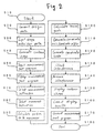
- Fig. 2 is a flowchart showing a measurement support method employed by the measurement support apparatus 10 to inspect or correct the measurement part program 30.
- the contour shape data for the workpiece are extracted from the design data, and are converted into the shape definition data 30 (S20).
- the shape definition data 30 are created based on the shape data (S20).
- the first row and the last row indicate the definition start and the definition end for a workpiece name OBJECT30.
- OUTBEGIN and OUTEND indicate the definition start and the definition end of a workpiece outer contour line
- INBEGIN and INEND indicate the definition start and the definition end of a workpiece internal contour line.
- P1 to P10 represent the unit elements for defining the coordinates for points, and ROTATE : Z, 360 indicates an expansion element for rotating the points 360° around the Z axis and generating a plane.
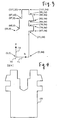
- a group of points that are defined by the shape definition data is shown in Fig. 3.
- an origin 70, a Z axis 72 and an R axis 74 are also indicated, while the coordinate values for the individual points are represented by the form (Z, R).
- the shape definition data 30 are entered and stored in a storage device (not shown) (S30).
- the conversion of the design data (S20) and the input of the shape definition data 30 (S30) are performed by the shape definition data input section 12.
- the contour shape of the workpiece is generated by the contour shape generator 14 (S40).
- the contour shape generator 14 When the group of points in Fig. 3 is rotated around the Z axis, the contour shape of the cylindrical workpiece is generated. Across section 68 of this contour shape is shown in Fig. 4.
- the measurement part program 40 is entered and stored in a storage device (not shown) by the measurement part program input section 16 (S50).
- An example measurement part program 40 is shown in Fig. 5.
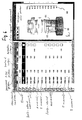
- FIG. 6 An example screen on which the measurement part program 40 is displayed is shown in Fig. 6.
- this instruction is selected by the measurement part program input section 16 (S70 or S80), and is highlighted by the display unit 22.
- the measurement part program 40 and the selected instruction to be highlighted are analyzed by the analyzer 18, and the portion to be measured and the travel path are calculated (S90 and S100). At this time, a highlight mark is provided for the portion to be measured or for the travel path that corresponds to the selected instruction, and in the succeeding process (S150), the pertinent portion or the travel path is highlighted and displayed by the display unit 22.
- FIG. 7 An example display is shown in Fig. 7, i.e., a contour shape image Wi of a workpiece, portions Pm1 and Pm2 that are to be measured and travel paths T1, T2 and T3 are displayed.
- a probe starts at a point Ps, through a point P1, to measure the portion Pm1, and returns thereafter to the point P1 and then moves to a point P2. After the portion Pm2 has been measured, the probe returns to the point P2. Then, the probe is positioned at apoint Pe to terminate themeasurement .
- the portion Pm2 and the travel path T2 (the path traveled from the point P1 to the point P2) are highlighted by a solid line.
- the analyzer 18 employs the analysis results obtained for the measurement part program 40 to generate coordinate axes (a Z axis 62 and an R axis 64) and a coordinate origin 60 (see Fig. 6) (S110).
- the analyzer 80 can also employ the contour shape generation results to generate coordinate axes (the Z axis 72 and the R axis 74) and the coordinate origin 70 (see Fig. 3).
- the analyzer 18 generates a coordinate scale 66 (see Fig. 6) (S120).
- the analyzer 18 checks an interference portion between the contour shape and the portion to be measured or the travel path (S130). During this check, the analyzer 18 checks whether the portions Pm1 and Pm2, which are to be measured, or the travel paths T1, T2 and T3 interfere with the substance portion Wi of the contour shape image of the workpiece. In the example in Fig. 7, the state wherein the travel path T2 interferes with the substance portion Wi in an area A1 is indicated by a thick broken line.
- the corrector 24 removes the interference based on information for the interference area A1 (S140). In the example in Fig. 7, a travel path T4 is generated instead of the travel path T2.
- the synthesizer 20 synthesizes the contour shape, the portions Pm1 and Pm2, which are to be measured, the travel paths T1 to T4, the coordinate axes 62 and 64 or 72 and 74, the coordinate origin 60 or 70, and the coordinate scale 66 and generates a display image. This image is displayed on the display unit 22 (S150).
- the display image for the portion to be measured or the travel path can be manually corrected on the display unit 22 by manipulating an input device, such as a keyboard, a mouse, a cursor key or a light pen.
- an input device such as a keyboard, a mouse, a cursor key or a light pen.
- the thus corrected measurement part program 50 is output by the corrected measurement part program output section 26.
- the measurement part program may be executed by a surface property measuring instrument other than a true circle measuring instrument, such as a surface roughness measuring instrument, a contour shape measuring instrument or a three-dimensional measuring instrument.
- a cross-sectional view (Fig. 4) or a semi-see-through perspective view (Fig. 6) is displayed; however, a solid diagram may be employed that does not have a transparent portion.
- the image, including the contour shape may be provided from an arbitrary viewpoint, as a perspective view, for which an arbitrary viewing direction, is designated using a mouse or a keyboard, or the contour shape may be displayed inverted (e.g., as an upside-down display).
- arbitrary colors, or a blinking display may be employed to make it easy to identify the contour shape, the portions to be measured, the travel paths, the coordinate axes, the coordinate origin, the coordinate scale, the interference portion, and the highlighted portion to be measured and the highlighted travel paths. Items that are not required for the display may be omitted.
- coordinate values may additionally be displayed for a selected measured portion or a travel path, or for designated points along the contour shape.
- selected portions of the display image may be arbitrarily enlarged or reduced.
- arbitrary data entered using a keyboard e.g., the name of an inspecting person, an inspection date, a correction date, the name of a workpiece, the model of the workpiece and the model of the measurement apparatus used
- a keyboard e.g., the name of an inspecting person, an inspection date, a correction date, the name of a workpiece, the model of the workpiece and the model of the measurement apparatus used
Landscapes
- Engineering & Computer Science (AREA)
- Human Computer Interaction (AREA)
- Manufacturing & Machinery (AREA)
- Physics & Mathematics (AREA)
- General Physics & Mathematics (AREA)
- Automation & Control Theory (AREA)
- Length Measuring Devices With Unspecified Measuring Means (AREA)
- A Measuring Device Byusing Mechanical Method (AREA)
- Image Analysis (AREA)
- Length Measuring Devices By Optical Means (AREA)
Abstract
Description
START:OBJECT30
OUTBEGIN:
P1:0,24
P2:57,24
P3:57,34
P4:70,34
P5:70,24
P6:82,24
P7:82,34
P8:95,32
P9: 95, 24
P10:107,24
ROTATE:Z,360
OUTEND:
INBEGIN:
P1:107,13
P2:87,13
P3:87,8
P4:66,8
P5: 62, 0
ROTATE:Z,360
INEND:
END:OBJECT30
Claims (15)
- A method for supporting a measurement of an object to be measured, the method comprises:wherein at the display step, the portion to be measured is displayed while superimposed on the contour shape.entering shape definition data for an obj ect to be measured;generating a contour shape based on the shape definition data;displaying the contour shape;entering a measurement part program; andanalyzing the measurement part program to obtain a portion to be measured,
- A measurement support method according to claim 1, further comprising:wherein at the display step, the travel path is displayed while superimposed on the contour shape.analyzing the measurement part program to obtain a travel path,
- A measurement support method according to claim 2, further comprising:wherein at the display step, the interference portion is displayed while superimposed on the contour shape.checking an interference portion between the portion to be measured or the travel path, and the contour shape,
- A measurement support method according to one of claims 1 to 3, further comprising:correcting the measurement part program based on results obtained by correcting the portion to be measured which is displayed.
- A measurement support method according to claim 2 or 3, further comprising:correcting the measurement part program based on results obtained by correcting the travel path that is displayed.
- A measurement support method according to claim 3, further comprising:correcting the portion to be measured or the travel path based on the interference portion_to eliminate the interference portion; andcorrecting the measurement part program based on the elimination of the interference portion.
- A measurement support method according to one of claims 1 to 6, further comprising:converting design data into shape definition data for the object to be measured.
- A measurement support method according to one of claims 1 to 7, further comprising:wherein at the display step, at the least one of the coordinate axes and the coordinate origin that is generated is displayed while superimposed on the contour shape.generating at least one of coordinate axes and a coordinate origin by employing the measurement part program or the shape definition data,
- A measurement support method according to one of claims 1 to 8, further comprising:wherein at the display step, the coordinate scale that is generated is displayed while superimposed on the contour shape.generating coordinate scale based on the measurement part program or the shape definition data,
- A measurement support method according to one of claims 1 to 9, further comprising:wherein at the step of calculating the portion to be measured, a portion corresponding to the selected measurement instruction is highlighted and output.displaying the measurement part program with the contour shape; andselecting a measurement instruction included in the measurement part program that is displayed,
- A measurement support method according to claim 2, 3, 5 or 6, further comprising:wherein at the step of calculating the travel path, a travel path corresponding to the selected movement instruction is highlighted and output.displaying the measurement part program and the contour shape at the same time; andselecting a movement instruction included in the measurement part program that is displayed,
- A measurement support method according to one of claims 1 to 11, wherein the shape definition data for the object to be measured includes at least one unit element of a zero-dimensional element, which is a point, a one-dimensional element, which is a line segment, or a two-dimensional element, which includes an arc.
- A measurement support method according to claim 12, wherein the shape definition data of the object to be measured further includes an expansion element for the rotation of the unit element or for the parallel movement of the unit element.
- An apparatus for supporting a measurement of an obj ect to be measured, the apparatus comprising:a shape definition data input section for entering shape definition data for an object to be measured;a contour shape generator for generating a contour shape based on the shape definition data;a measurement part program input section for entering a measurement part program;an analyzer for analyzing the measurement part program and outputting analysis results;a synthesizer for synthesizing the analysis results with the contour shape; anda display unit for displaying a synthesized image obtained based on the synthesis results.
- A measurement support apparatus according to claim 14, further comprising:a corrector for correcting the synthesized image that is displayed; anda corrected measurement part program output section for correcting the measurement part program based on the corrected synthesized image and outputting the corrected measurement part program.
Applications Claiming Priority (2)
| Application Number | Priority Date | Filing Date | Title |
|---|---|---|---|
| JP2002269447A JP4024117B2 (en) | 2002-09-17 | 2002-09-17 | Measurement support device |
| JP2002269447 | 2002-09-17 |
Publications (2)
| Publication Number | Publication Date |
|---|---|
| EP1400881A2 true EP1400881A2 (en) | 2004-03-24 |
| EP1400881A3 EP1400881A3 (en) | 2009-04-08 |
Family
ID=31944511
Family Applications (1)
| Application Number | Title | Priority Date | Filing Date |
|---|---|---|---|
| EP03020965A Ceased EP1400881A3 (en) | 2002-09-17 | 2003-09-16 | Method and apparatus for supporting measurement of object to be measured |
Country Status (3)
| Country | Link |
|---|---|
| US (1) | US7069175B2 (en) |
| EP (1) | EP1400881A3 (en) |
| JP (1) | JP4024117B2 (en) |
Families Citing this family (15)
| Publication number | Priority date | Publication date | Assignee | Title |
|---|---|---|---|---|
| JP2006308476A (en) * | 2005-04-28 | 2006-11-09 | Tokyo Seimitsu Co Ltd | Apparatus for measuring surface roughness/shape |
| DE102009004285A1 (en) | 2008-06-27 | 2009-12-31 | Robert Bosch Gmbh | Method and device for optimizing, monitoring or analyzing a process |
| JP5483894B2 (en) * | 2009-01-30 | 2014-05-07 | 株式会社牧野フライス製作所 | Measuring program checking method and measuring function machine |
| JP5417222B2 (en) * | 2010-03-05 | 2014-02-12 | 株式会社ミツトヨ | Tolerance detection method and apparatus for roundness measuring machine |
| CN102955695A (en) * | 2011-08-31 | 2013-03-06 | 鸿富锦精密工业(深圳)有限公司 | Three-dimensional measurement program color management system and method |
| US9235337B2 (en) * | 2013-05-09 | 2016-01-12 | Mitutoyo Corporation | System, GUI and method for editing step and repeat operation instructions in a machine vision inspection system |
| US9639083B2 (en) * | 2013-12-18 | 2017-05-02 | Mitutoyo Corporation | System and method for programming workpiece feature inspection operations for a coordinate measuring machine |
| CN105793787B (en) * | 2013-12-27 | 2019-10-18 | 株式会社牧野铣床制作所 | The control device of work mechanism |
| JP6579682B2 (en) * | 2014-07-18 | 2019-09-25 | 株式会社ミツトヨ | Image measuring device |
| JP6647094B2 (en) * | 2016-03-16 | 2020-02-14 | 株式会社ミツトヨ | Part program generator for surface texture measuring machine |
| WO2019043861A1 (en) * | 2017-08-31 | 2019-03-07 | 三菱重工機械システム株式会社 | Monitoring device, monitoring method, and program |
| JP7240831B2 (en) * | 2018-07-20 | 2023-03-16 | 株式会社ミツトヨ | AUTOMATIC PART PROGRAM GENERATION DEVICE FOR ROUNDITY MEASURING MACHINE, ROUNDITY MEASURING DEVICE, AND METHOD OF AUTOMATIC PART PROGRAM GENERATION FOR ROUNDITY MEASURING MACHINE |
| JP7324085B2 (en) * | 2019-08-09 | 2023-08-09 | ファナック株式会社 | Machining program generation support device |
| JP7267875B2 (en) * | 2019-08-29 | 2023-05-02 | 株式会社ミツトヨ | 1D measuring machine |
| JP2023003731A (en) * | 2021-06-24 | 2023-01-17 | キヤノン株式会社 | Information processing device, information processing method, display device, display method, robot system, method for manufacturing article, program and recording medium |
Family Cites Families (9)
| Publication number | Priority date | Publication date | Assignee | Title |
|---|---|---|---|---|
| JPS63206607A (en) | 1987-02-23 | 1988-08-25 | Mitsutoyo Corp | Three-dimensional measuring machine |
| JP2578241B2 (en) | 1990-04-05 | 1997-02-05 | 松下電器産業株式会社 | Automatic program creation device |
| JPH04134561A (en) * | 1990-09-26 | 1992-05-08 | Mutoh Ind Ltd | Input device for cad |
| JPH0829152A (en) | 1994-07-15 | 1996-02-02 | Tokyo Seimitsu Co Ltd | Measurement treatment method and device of coordinate measuring instrument |
| JPH08339215A (en) | 1995-06-13 | 1996-12-24 | Fanuc Ltd | Numerical controller |
| JPH0991019A (en) | 1995-09-25 | 1997-04-04 | Tokai Univ | Computer-aided design system and computer-aided design and production system for producing based on data obtained by this system |
| JP3455391B2 (en) * | 1997-04-22 | 2003-10-14 | 株式会社ミツトヨ | Measurement support system |
| JP3989108B2 (en) | 1998-11-27 | 2007-10-10 | 株式会社ミツトヨ | Measuring machine and moving path determination method thereof |
| JP3853620B2 (en) * | 2001-08-21 | 2006-12-06 | 株式会社ミツトヨ | Part program generation device and program for image measurement device |
-
2002
- 2002-09-17 JP JP2002269447A patent/JP4024117B2/en not_active Expired - Fee Related
-
2003
- 2003-09-03 US US10/653,224 patent/US7069175B2/en not_active Expired - Lifetime
- 2003-09-16 EP EP03020965A patent/EP1400881A3/en not_active Ceased
Also Published As
| Publication number | Publication date |
|---|---|
| EP1400881A3 (en) | 2009-04-08 |
| US20040054502A1 (en) | 2004-03-18 |
| US7069175B2 (en) | 2006-06-27 |
| JP4024117B2 (en) | 2007-12-19 |
| JP2004108852A (en) | 2004-04-08 |
Similar Documents
| Publication | Publication Date | Title |
|---|---|---|
| US7069175B2 (en) | Method and apparatus for supporting measurement of object to be measured | |
| JP3732494B2 (en) | Simulation device | |
| US20030090483A1 (en) | Simulation apparatus for working machine | |
| Chen et al. | A comprehensive error analysis method for the geometric error of multi-axis machine tool | |
| US7333879B2 (en) | Offline programming device | |
| US20130282328A1 (en) | Error measurment device and error measurement method | |
| US7062352B2 (en) | Method for displaying tool locus in NC data and method for analyzing NC data | |
| US8212993B2 (en) | Method and apparatus for surveying actual measurement data of a component | |
| EP0697639B1 (en) | Inspection device and method for checking interference | |
| JP2009175954A (en) | Generating device of processing robot program | |
| GB2194367A (en) | Computer-aided inspection system | |
| CN103106076A (en) | Machine vision inspection system and method for editing part program on the machine vision inspection system | |
| JP2020086759A (en) | 3D model creation device, machining simulation device, automatic tool path generation device | |
| JP2012125871A (en) | Robot control setting support device | |
| JP6316513B1 (en) | Machining program analyzer | |
| US20050038624A1 (en) | Apparatus for integrated tool manufacture and method therefor | |
| KR20100135513A (en) | Numerical control system with graphical user interface | |
| JP3066646B2 (en) | Motion simulation system | |
| US20190235473A1 (en) | Machining simulation display apparatus and machining simulation display method | |
| US20140172144A1 (en) | System and Method for Determining Surface Defects | |
| GB2230363A (en) | Tolerance analysis in cad system | |
| JP2004021953A (en) | NC data tool path display method and NC data analysis method | |
| US20240337483A1 (en) | Mapping of sensor error data from a coordinate positioning machine | |
| EP4212822A1 (en) | Mapping of sensor error data from a coordinate positioning machine | |
| JP2024061276A (en) | Measurement program generation method and three-dimensional coordinate measuring machine |
Legal Events
| Date | Code | Title | Description |
|---|---|---|---|
| PUAI | Public reference made under article 153(3) epc to a published international application that has entered the european phase |
Free format text: ORIGINAL CODE: 0009012 |
|
| AK | Designated contracting states |
Kind code of ref document: A2 Designated state(s): AT BE BG CH CY CZ DE DK EE ES FI FR GB GR HU IE IT LI LU MC NL PT RO SE SI SK TR |
|
| AX | Request for extension of the european patent |
Extension state: AL LT LV MK |
|
| PUAL | Search report despatched |
Free format text: ORIGINAL CODE: 0009013 |
|
| AK | Designated contracting states |
Kind code of ref document: A3 Designated state(s): AT BE BG CH CY CZ DE DK EE ES FI FR GB GR HU IE IT LI LU MC NL PT RO SE SI SK TR |
|
| AX | Request for extension of the european patent |
Extension state: AL LT LV MK |
|
| 17P | Request for examination filed |
Effective date: 20090806 |
|
| AKX | Designation fees paid |
Designated state(s): DE FR GB |
|
| 17Q | First examination report despatched |
Effective date: 20091203 |
|
| STAA | Information on the status of an ep patent application or granted ep patent |
Free format text: STATUS: THE APPLICATION HAS BEEN REFUSED |
|
| 18R | Application refused |
Effective date: 20101213 |