EP1400681A2 - Methods and apparatus for supporting high temperature ducting - Google Patents
Methods and apparatus for supporting high temperature ducting Download PDFInfo
- Publication number
- EP1400681A2 EP1400681A2 EP03255787A EP03255787A EP1400681A2 EP 1400681 A2 EP1400681 A2 EP 1400681A2 EP 03255787 A EP03255787 A EP 03255787A EP 03255787 A EP03255787 A EP 03255787A EP 1400681 A2 EP1400681 A2 EP 1400681A2
- Authority
- EP
- European Patent Office
- Prior art keywords
- tube support
- inner tube
- support member
- duct
- extending
- Prior art date
- Legal status (The legal status is an assumption and is not a legal conclusion. Google has not performed a legal analysis and makes no representation as to the accuracy of the status listed.)
- Withdrawn
Links
Images



Classifications
-
- F—MECHANICAL ENGINEERING; LIGHTING; HEATING; WEAPONS; BLASTING
- F02—COMBUSTION ENGINES; HOT-GAS OR COMBUSTION-PRODUCT ENGINE PLANTS
- F02K—JET-PROPULSION PLANTS
- F02K1/00—Plants characterised by the form or arrangement of the jet pipe or nozzle; Jet pipes or nozzles peculiar thereto
- F02K1/78—Other construction of jet pipes
- F02K1/80—Couplings or connections
-
- F—MECHANICAL ENGINEERING; LIGHTING; HEATING; WEAPONS; BLASTING
- F01—MACHINES OR ENGINES IN GENERAL; ENGINE PLANTS IN GENERAL; STEAM ENGINES
- F01D—NON-POSITIVE DISPLACEMENT MACHINES OR ENGINES, e.g. STEAM TURBINES
- F01D25/00—Component parts, details, or accessories, not provided for in, or of interest apart from, other groups
- F01D25/24—Casings; Casing parts, e.g. diaphragms, casing fastenings
- F01D25/243—Flange connections; Bolting arrangements
-
- F—MECHANICAL ENGINEERING; LIGHTING; HEATING; WEAPONS; BLASTING
- F05—INDEXING SCHEMES RELATING TO ENGINES OR PUMPS IN VARIOUS SUBCLASSES OF CLASSES F01-F04
- F05D—INDEXING SCHEME FOR ASPECTS RELATING TO NON-POSITIVE-DISPLACEMENT MACHINES OR ENGINES, GAS-TURBINES OR JET-PROPULSION PLANTS
- F05D2260/00—Function
- F05D2260/20—Heat transfer, e.g. cooling
- F05D2260/231—Preventing heat transfer
-
- F—MECHANICAL ENGINEERING; LIGHTING; HEATING; WEAPONS; BLASTING
- F05—INDEXING SCHEMES RELATING TO ENGINES OR PUMPS IN VARIOUS SUBCLASSES OF CLASSES F01-F04
- F05D—INDEXING SCHEME FOR ASPECTS RELATING TO NON-POSITIVE-DISPLACEMENT MACHINES OR ENGINES, GAS-TURBINES OR JET-PROPULSION PLANTS
- F05D2260/00—Function
- F05D2260/30—Retaining components in desired mutual position
Definitions
- This invention relates generally to gas turbine engines, and more specifically to ducts which carry high temperature fluids within gas turbine engines.
- At least some known gas turbine engines include a core engine having, in serial flow arrangement, a fan assembly and a high pressure compressor which compress airflow entering the engine, a combustor ignites a fuel-air mixture which is then channeled through a turbine nozzle assembly towards low and high pressure turbines which each include a plurality of rotor blades that extract rotational energy from airflow exiting the combustor.
- at least some known gas turbine engines include ducting that routes high temperature fluids from one area of the engine for use in another area of the engine. For example, ducting may carry high temperature bleed air having a temperature of at least 1000° F for use in an engine anti-icing system.
- an external surface of the ducting may rise in temperature through heat transfer.
- such ducting may be routed through areas of the engine which are not as thermally resistant as the ducting.
- an external surface temperature limit of less than 400° F is imposed on the external surfaces of the anti-icing ducting.
- At least some known ducting is wrapped with insulation. Furthermore, to maintain the structural rigidity and integrity of the ducting, the ducting is coupled to the engine with metallic bracket assemblies. To facilitate providing structural support to the ducting, without facilitating heat transfer through the support, at least some known bracket assemblies include inner tube supports that extend circumferentially around the duct.
- Each inner tube supports has a substantially frusto-conical or wish-boned cross-sectional profile defined by a radially outer portion and a radially inner portion which are connected together at an apex that is substantially parallel the duct external surface. Insulation is then wrapped around the duct in the area between the inner tube supports, and a separate outer tube support is then welded or otherwise joined to the inner tube supports and the duct. Alternatively, the outer tube support is coupled to the supports and insulation material is injected into the cavity.
- insulation is wrapped around the duct adjacent to each inner tube support, prior to a polyimide outer wrap, or a wrap fabricated from a similar composite based material, being extended around the insulation and a portion of the outer tube support.
- a mounting bracket is then coupled to the outer tube support.
- the outer tube support incorporates the mounting bracket, in the form of a casting.
- a method for coupling a duct to a gas turbine engine casing comprises extending a first inner tube support member circumferentially around the duct, such that a radially inner side of the first inner tube support is against the duct, and wherein the first inner tube support member has a substantially curved cross sectional profile extending between the radially inner side of the first inner tube support, and a radially outer side of the first inner tube support.
- the method also comprises extending an outer tube support member circumferentially around the first inner tube support member such that the outer tube support member is against the first inner tube support member outer surface, and coupling the outer tube support member to the gas turbine engine casing.
- a bracket assembly for a duct in another aspect of the invention, includes a first inner tube support member that extends circumferentially around the duct, and an outer tube support member that extends circumferentially around the first inner tube support member.
- the first inner tube support includes a radially outer side, a radially inner side against the duct, and a body extending therebetween, wherein the body has a substantially smooth arcuate cross-sectional profile extending between the radially inner and outer sides.
- a duct for a gas turbine engine including a casing includes a tube for transporting a fluid therein, and a bracket assembly for securing the tube to the engine casing.
- the bracket assembly is configured to reduce heat transfer from the tube to the engine casing.
- the bracket assembly includes a first inner tube support member and an outer tube support member.
- the first inner tube support member extends circumferentially around the tube such that a radially inner side of the first inner tube support member is against the tube.
- the outer tube support member extends circumferentially around the inner tube support member, such that a radially outer side of the first support member is against the outer tube support member.
- the first inner tube support member has a substantially semi-elliptical cross-sectional profile extending between the first inner tube support radially inner and outer sides.
- Figure 1 is a schematic illustration of a gas turbine engine 10 including a low pressure compressor 12, a high pressure compressor 14, and a combustor 16.
- Engine 10 also includes a high pressure turbine 18 and a low pressure turbine 20.
- Compressor 12 and turbine 20 are coupled by a first shaft 24, and compressor 14 and turbine 18 are coupled by a second shaft 26.
- the gas turbine engine is a GE90 available from General Electric Company, Cincinnati, Ohio.
- the highly compressed air is delivered to combustor 16.
- Airflow from combustor 16 drives turbines 18 and 20 before exiting gas turbine engine 10.
- Figure 2 is an enlarged partial cross-sectional view of a known bracket assembly 40 that may be used to couple a duct 42 within a gas turbine engine, such as engine 10 (shown in Figure 1). More specifically duct 42 is used to channel high temperature fluids from a first engine location for use at a second engine location. For example, in one embodiment, duct 42 is used to transport temperature bleed air for use with an engine anti-icing system and channels air which has a temperature of at least 1000° F.
- Bracket assembly 40 includes an inner tube support assembly 44, an outer tube support structure 46, and an external wrap 48.
- Inner tube support assembly 44 includes a pair of substantially identical inner tube supports 50 and 52, respectively, that each include a formed radially outer member 54 and a radially inner member 58.
- Each set of members 54 and 58 are coupled together midway between a radially outer side 66 of support assembly 44 and a radially inner side 68 of support assembly 44. More specifically, members 54 and 58 define a frusto-conical or wish-boned shaped cross-sectional profile for each tube support 50 and 52 when coupled. Accordingly, members 54 and 58 are joined at an apex 70 of the cross-sectional profile defined for each inner tube support 50 and 52.
- Members 50 and 52 each extend circumferentially around duct 42 and are each positioned against an external surface 80 of duct 42. More specifically, members 50 and 52 are spaced apart a distance 81, such that a gap 82 is defined therebetween. Gap 82 is thus also bordered by a portion 84 of duct external surface 80 and by a portion 86 of outer tube support structure 46.
- Outer tube support structure 46 extends circumferentially around duct 42 and around inner tube support assembly 44. More specifically, outer tube support structure 46 is coupled against inner tube support members 54.
- duct 42, members 50 and 52, and outer tube support structure 46 are each fabricated from a metallic material such as, but not limited to, Inco® 625.
- a mounting bracket (not shown) is then coupled to outer tube support structure 46 for coupling duct 42 to gas turbine engine 10.
- Insulation 90 is extended around duct 42 between inner tube support members 50 and 52 within gap 82. More specifically, insulation 90 is extended through gap 82 within a radially inner portion 92 of gap 82 and within a radially outer portion 94 of gap 82. Gap radially inner portion 92 extends from duct external surface 80 towards each inner tube support apex 70, and gap radially outer portion 94 extends from outer tube support structure 46 towards each inner tube support apex 70. Accordingly, a portion 96 of gap 82 between each inner tube support apex 70 remains uninsulated.
- Additional insulation 98 is extended around duct 42 adjacent members 50 and 52, but external to gap 82. Insulation 98 is covered by external wrap 48 which is extended circumferentially around duct 42 over insulation 98. Furthermore, wrap 48 is extended at least partially over outer tube support structure 46, such that an edge 100 of outer tube support structure 46 and an outer edge 102 of each inner tube support member 54 is covered by wrap 48.
- wrap 48 is fabricated from a polymide material, and insulation 90 and 98 are each fabricated from the same material, such as, but not limited to Min-K® insulation.
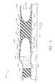
- FIG 3 is an enlarged partial cross-sectional view of a bracket assembly 200 that may be used to couple duct 42 to a gas turbine engine, such as gas turbine engine 10 (shown in Figure 1).
- Figure 4 is an enlarged perspective view of bracket assembly 200.
- Bracket assembly 200 includes an inner tube support assembly 202, an outer tube support structure 204, an outer wrap 206, and a mounting bracket 208.
- Inner tube support assembly 202 includes a pair of substantially identical inner tube support members 220 and 222, respectively.
- each tube support members 220 and 222 is a one piece assembly extending between a radially outer side 224 of inner tube support assembly 202 to a radially inner side 226 of inner tube support assembly 202.
- each tube support members 220 and 222 is fabricated from a plurality of formed pieces coupled together to form each support member 220 and 222.
- Support members 220 and 222 each have a substantially arcuate cross-sectional profile that extends smoothly between inner tube support assembly sides 224 and 226. More specifically, members 220 and 222 each have a substantially semi-elliptical cross-sectional profile.
- members 220 and 222 each have a non-substantially semi-elliptical cross-sectional profile.
- members 220 and 220 include substantially planar portions and include only a partial elliptical cross-sectional profile that is positioned midway between duct 42 and outer tube support structure 204.
- members 220 and 222 do not include any corners between inner tube support assembly sides 224 and 226.
- Members 220 and 222 each extend circumferentially around duct 42 and are each positioned against duct external surface 80. More specifically, members 220 and 222 are spaced a distance 230, such that a gap 232 is defined between members 220 and 222. Gap 232 is thus also bordered by a portion 234 of duct external surface 80 and by a portion 236 of outer tube support structure 204.
- Outer tube support structure 204 extends circumferentially around duct 42 and around inner tube support assembly 202 such that support structure 204 is substantially parallel duct external surface 80. More specifically, outer tube support structure 204 is coupled against inner tube support members 220 and 222 such that outer tube support structure 204 extends from a radially outer edge 240 of member 220 to a radially outer edge 242 of member 222.
- duct 42, members 220 and 222, and outer tube support structure 204 are each fabricated from a metallic material such as, but not limited to, Inco® 625.
- Insulation 250 is extended circumferentially around duct 42 between inner tube support members 220 and 222 within gap 232. More specifically, insulation 250 substantially fills gap 232 laterally between members 220 and 222, and radially between duct 42 and outer tube support structure 204.
- a ceramic spacer 260 is extended circumferentially around duct 42 adjacent member 220 such that a gap 262 is defined between an upstream side 264 of member 220 and ceramic spacer 260.
- ceramic spacer 260 is also extended circumferentially around duct 42 adjacent member 222 such that a gap (not shown) is defined between a downstream side 268 of member 222 and ceramic spacer 260.
- Additional insulation 270 is extended around duct 42 against each each side 272 and 274 of ceramic spacer 260, such that gap 262 is substantially filled by insulation 270.
- insulation 270 also substantially fills the gap defined between ceramic spacer 260 and member downstream side 268.
- insulation 250 is not used within gap 232, but rather an additional ceramic spacer substantially fills gap 232.
- Insulation 270 and ceramic spacer 260 are each covered by external wrap 206 which is extended circumferentially around duct 42 over insulation 270 and ceramic spacer 260. Furthermore, wrap 206 is extended at least partially over outer tube support structure 204, such that an edge 280 of outer tube support structure 204 and inner tube support member radially outer edge 240 is covered by wrap 206.
- wrap 206 is fabricated from a polymide material, and insulation 250 and 270 are each fabricated from the same material, such as, but not limited to Min-K® insulation.
- Mounting bracket 208 is coupled to outer tube support structure 204 for coupling duct 42 to gas turbine engine 10. More specifically, mounting bracket 208 includes a base 290 that is contoured to substantially match a contour of outer tube support structure 204. Bracket 208 includes a pair of flanges 292 that extend substantially perpendicularly from base 290. Flanges 292 include a plurality of openings 294 sized to receive a fastener (not shown) therethrough for coupling mounting bracket 208 and duct 42 to gas turbine engine 10.
- bracket assembly 200 facilitates reducing stress concentrations that may be induced in bracket assemblies 40 that include inner tube supports 50 and 52 which include corners 70. Furthermore, the smooth transition of each tube member 220 and 222 facilitates reducing stress concentrations, such that the structural rigidity and structural integrity of bracket assembly 200 are not compromised. Furthermore, because bracket assembly 200 includes additional insulation 250 and 270 in comparison to other known bracket assemblies 40, bracket assembly 200 facilitates reducing temperature transmission to engine 10 through mounting bracket 208. In addition, bracket assembly 200 also uses fewer components than bracket assembly 40, and as such, manufacturing and assembly costs are facilitated to be reduced.
- Each bracket assembly includes an inner tube support that includes a smooth transition between the outer tube support and the duct. Accordingly, the inner tube support facilitates reducing stress concentrations that may be induced to the bracket assembly. Furthermore, the bracket assembly includes additional insulation that facilitates reducing heat transfer through the mounting bracket. Accordingly, the above-described bracket assembly facilitates extending a useful life of the high temperature duct in a cost-effective and reliable manner.
- bracket assemblies are described above in detail.
- the assemblies are not limited to the specific embodiments described herein, but rather, components of each assembly may be utilized independently and separately from other components described herein.
- Each bracket assembly component can also be used in combination with other bracket assembly components.
Landscapes
- Engineering & Computer Science (AREA)
- Mechanical Engineering (AREA)
- General Engineering & Computer Science (AREA)
- Chemical & Material Sciences (AREA)
- Combustion & Propulsion (AREA)
- Thermal Insulation (AREA)
- Turbine Rotor Nozzle Sealing (AREA)
- Structures Of Non-Positive Displacement Pumps (AREA)
Abstract
Description
Claims (10)
- A method for coupling a duct (42) to a gas turbine engine casing, said method comprising:extending a first inner tube support member (220) circumferentially around the duct, such that a radially inner side (226) of the first inner tube support is against the duct, and wherein the first inner tube support member has a substantially curved cross sectional profile extending between the radially inner side of the first inner tube support, and a radially outer side (224) of the first inner tube support;extending an outer tube support member (204) circumferentially around the first inner tube support member such that the outer tube support member is against the first inner tube support member outer surface; andcoupling the outer tube support member to the gas turbine engine casing.
- A method in accordance with Claim 1 further comprising extending a second inner tube support member (222) circumferentially around the duct (42), wherein the first inner tube support member (220) is a mirror image of the second inner tube support, and such that a gap (232) is defined between the first and second inner tube support members.
- A method in accordance with Claim 2 further comprising extending at least one of insulation (250) and a ceramic spacer (260) around the tube (42) such that at least one of the insulation and the ceramic spacer substantially fill the gap (232) between the fist (220) and second (222) inner tube support members.
- A method in accordance with Claim 2 further comprising:extending insulation (250) around the tube against the first inner tube support member inner (226) and outer sides (224);extending a ceramic spacer (260) around the tube such that the ceramic spacer is against insulation that is between the first inner tube support member (280)and the ceramic spacer;extending a wrap (206) around the ceramic spacer and at least a portion (280) of the outer tube support member (204).
- A bracket assembly (200) for a duct (42), said bracket assembly comprising:a first inner tube support member (220) extending circumferentially around the duct, said first inner tube support comprising a radially outer side (224), a radially inner side (226) against the duct, and a body extending therebetween, said body having a substantially smooth arcuate cross-sectional profile extending between said radially inner and outer sides; andan outer tube support member (204) extending circumferentially around said first inner tube support member.
- A bracket assembly (200) in accordance with Claim 5 wherein said body has a substantially semi-elliptical cross-sectional profile extending between said radially inner (226) and outer (224) sides.
- A bracket assembly (200) in accordance with Claim 5 further comprising a second inner tube support (222) extending circumferentially around the duct (42), said first inner tube support (220) substantially a mirror image of said second inner tube support, said first and said second inner tube supports spaced apart to define a gap (232) therebetween.
- A duct (42) for a gas turbine engine (10) including a casing, said duct comprising:a tube for transporting a fluid therein; anda bracket assembly (200) for securing said tube to the engine casing, said bracket assembly configured to reduce heat transfer from said tube to the engine casing, said bracket assembly comprising a first inner tube support member (220) and an outer tube support member (204), said first inner tube support member extending circumferentially around said tube such that a radially inner side (226) of said first inner tube support member is against said tube, an outer tube support member extending circumferentially around said inner tube support member, such that a radially outer side (224) of said first support member is against said outer tube support member, said first inner tube support member having a substantially semi-elliptical cross-sectional profile extending between said first inner tube support radially inner and outer sides.
- A duct (42) in accordance with Claim 8 wherein said bracket assembly (200) further comprises a second inner tube support (222) extending circumferentially around said tube, said first inner tube support (220) substantially a mirror image of said second inner tube support, said first and said second inner tube supports spaced apart to define a gap (232) therebetween.
- A duct (42) in accordance with Claim 9 wherein said bracket assembly (200) further comprises at least one of a ceramic spacer (260) and insulation (250) extending circumferentially around said tube and substantially filling said gap (232) defined between said first (220) and second (222) inner tube support members.
Applications Claiming Priority (2)
| Application Number | Priority Date | Filing Date | Title |
|---|---|---|---|
| US251557 | 1994-05-31 | ||
| US10/251,557 US6715297B1 (en) | 2002-09-20 | 2002-09-20 | Methods and apparatus for supporting high temperature ducting |
Publications (2)
| Publication Number | Publication Date |
|---|---|
| EP1400681A2 true EP1400681A2 (en) | 2004-03-24 |
| EP1400681A3 EP1400681A3 (en) | 2006-06-07 |
Family
ID=31946477
Family Applications (1)
| Application Number | Title | Priority Date | Filing Date |
|---|---|---|---|
| EP03255787A Withdrawn EP1400681A3 (en) | 2002-09-20 | 2003-09-16 | Methods and apparatus for supporting high temperature ducting |
Country Status (4)
| Country | Link |
|---|---|
| US (1) | US6715297B1 (en) |
| EP (1) | EP1400681A3 (en) |
| JP (1) | JP4471612B2 (en) |
| CN (1) | CN100379945C (en) |
Families Citing this family (9)
| Publication number | Priority date | Publication date | Assignee | Title |
|---|---|---|---|---|
| JP2005163812A (en) * | 2003-11-28 | 2005-06-23 | Nissan Motor Co Ltd | Support structure |
| US7197877B2 (en) * | 2004-08-04 | 2007-04-03 | Siemens Power Generation, Inc. | Support system for a pilot nozzle of a turbine engine |
| US7451541B2 (en) * | 2005-02-04 | 2008-11-18 | Pratt & Whitney Canada Corp. | Method of heat shielding an inner tube |
| EP2189630A1 (en) * | 2008-11-19 | 2010-05-26 | Siemens Aktiengesellschaft | Gas turbine, guide vane support for such a gas turbine and gas or steam turbine plant with such a gas turbine |
| WO2014172000A2 (en) * | 2013-02-07 | 2014-10-23 | United Technologies Corporation | System and method for aft mount of gas turbine engine |
| CN103437834B (en) * | 2013-08-30 | 2015-04-08 | 中国化学工程第三建设有限公司 | Stress-free mounting method of flange at inlet steam pipe section of turbine |
| US10677261B2 (en) * | 2017-04-13 | 2020-06-09 | General Electric Company | Turbine engine and containment assembly for use in a turbine engine |
| US10662813B2 (en) | 2017-04-13 | 2020-05-26 | General Electric Company | Turbine engine and containment assembly for use in a turbine engine |
| US10436061B2 (en) | 2017-04-13 | 2019-10-08 | General Electric Company | Tapered composite backsheet for use in a turbine engine containment assembly |
Family Cites Families (31)
| Publication number | Priority date | Publication date | Assignee | Title |
|---|---|---|---|---|
| US398620A (en) | 1889-02-26 | Leslie i | ||
| US600988A (en) | 1898-03-22 | Coupling | ||
| US96545A (en) | 1869-11-09 | Improvement in faucet-connection | ||
| US520514A (en) | 1894-05-29 | Alexander bryant | ||
| US821564A (en) | 1905-09-13 | 1906-05-22 | Modern Improvements Mfg Co | Coupling for pipes and tubes. |
| US1504363A (en) | 1921-01-20 | 1924-08-12 | Madigan Union Corp | Locked coupling |
| US1455971A (en) | 1921-07-21 | 1923-05-22 | Rickenbacker Adolph | Coupling |
| US1589781A (en) | 1925-11-09 | 1926-06-22 | Joseph M Anderson | Rotary tool joint |
| US2109344A (en) | 1937-05-28 | 1938-02-22 | Henry L Selger | Ground joint pipe coupling |
| DE1122469B (en) | 1959-04-24 | 1962-01-25 | Sandvikens Jernverks Ab | Catch sleeve for boring bars u. like |
| US3130747A (en) | 1961-05-15 | 1964-04-28 | Sterer Engineering And Mfg Com | Flow regulator |
| GB1103643A (en) * | 1966-07-22 | 1968-02-21 | Rolls Royce | Gas turbine engine |
| US3449937A (en) | 1967-06-23 | 1969-06-17 | Columbia Summerill Corp | High pressure fuel line heads and the like |
| GB1283953A (en) * | 1969-06-19 | 1972-08-02 | Rolls Royce | Wall for hot fluid streams |
| SE336642B (en) | 1969-10-28 | 1971-07-12 | Astra Meditec Ab | |
| US3838083A (en) | 1972-09-08 | 1974-09-24 | Asahi Glass Co Ltd | Oil-and water-repellent composition of perfluoroalkyl acrylates or methacrylates |
| US4415184A (en) * | 1981-04-27 | 1983-11-15 | General Electric Company | High temperature insulated casing |
| GB2114694B (en) | 1982-02-11 | 1985-04-11 | Conex Sanbra Limited | Bibcock assemblies |
| JP2789197B2 (en) | 1988-08-19 | 1998-08-20 | 臼井国際産業株式会社 | High-pressure metal pipe having a connection head and a method of forming the head |
| FR2657939B1 (en) | 1990-02-05 | 1992-05-15 | Simmonds Sa | IMPROVED WATERPROOF CONNECTION FOR CONDUITS OF TRANSPORT OF ANY FLUID. |
| US5363312A (en) * | 1990-03-30 | 1994-11-08 | Kabushiki Kaisha Toshiba | Method and apparatus for battery control |
| US5362110A (en) | 1991-02-25 | 1994-11-08 | Moeller Manufacturing Co., Inc. | Fluid coupling and fastener capture device |
| US5188398A (en) | 1992-01-02 | 1993-02-23 | General Electric Company | Redundantly locked fluid coupling |
| US5263312A (en) | 1992-07-21 | 1993-11-23 | General Electric Company | Tube fitting for a gas turbine engine |
| FR2699644B1 (en) | 1992-12-23 | 1995-01-20 | Snecma | Elastic ring with stress indicator for fitting. |
| US5321205B1 (en) | 1993-01-15 | 1997-02-04 | Thomas & Betts Corp | Electrical connector fitting |
| US5431507A (en) | 1993-07-12 | 1995-07-11 | Smilanick; Steve | Bicycle torque coupling |
| US5369952A (en) * | 1993-07-20 | 1994-12-06 | General Electric Company | Variable friction force damper |
| US5396918A (en) | 1993-11-18 | 1995-03-14 | Agricultural Products, Inc. | Water pressure regulator and method for regulating pressure through a valve |
| US5584511A (en) * | 1995-10-23 | 1996-12-17 | General Electric Company | Multi-degree-of-freedom expansion joint |
| JP2001041005A (en) * | 1999-08-02 | 2001-02-13 | Tohoku Electric Power Co Inc | Piping support of gas turbine steam cooled combustor |
-
2002
- 2002-09-20 US US10/251,557 patent/US6715297B1/en not_active Expired - Fee Related
-
2003
- 2003-09-16 EP EP03255787A patent/EP1400681A3/en not_active Withdrawn
- 2003-09-19 CN CNB031586570A patent/CN100379945C/en not_active Expired - Fee Related
- 2003-09-19 JP JP2003327077A patent/JP4471612B2/en not_active Expired - Fee Related
Also Published As
| Publication number | Publication date |
|---|---|
| CN100379945C (en) | 2008-04-09 |
| JP4471612B2 (en) | 2010-06-02 |
| US20040055311A1 (en) | 2004-03-25 |
| EP1400681A3 (en) | 2006-06-07 |
| US6715297B1 (en) | 2004-04-06 |
| JP2004116518A (en) | 2004-04-15 |
| CN1492128A (en) | 2004-04-28 |
Similar Documents
| Publication | Publication Date | Title |
|---|---|---|
| US10024193B2 (en) | Pin supported CMC shroud | |
| US6991427B2 (en) | Casing section | |
| US9810097B2 (en) | Corrugated mid-turbine frame thermal radiation shield | |
| EP2126289B1 (en) | Transition support system for combustion transition ducts for turbine engines | |
| EP3133248A1 (en) | Cmc nozzles with split endwalls for gas turbine engines | |
| EP1706594B1 (en) | Sliding joint between combustor wall and nozzle platform | |
| EP3118417A1 (en) | Shroud assembly for gas turbine engine | |
| EP3101233B1 (en) | Methods for positioning neighboring nozzles of a gas turbine engine | |
| US10281153B2 (en) | Combustor assembly | |
| US11629602B2 (en) | Cooling schemes for airfoils for gas turbine engines | |
| US10221712B2 (en) | Seal for hardware segments | |
| EP3211321B1 (en) | Combustor assembly | |
| US8747066B2 (en) | Gas turbine housing component | |
| JP2008133829A (en) | Equipment that facilitates loss reduction in turbine engines | |
| US6715297B1 (en) | Methods and apparatus for supporting high temperature ducting | |
| GB2458770A (en) | Supporting gas turbine stator components | |
| US20120134782A1 (en) | Purge systems for rotary machines and methods of assembling same | |
| US20250283416A1 (en) | Turbine vane with leading edge cooling | |
| CA2478202C (en) | Methods and apparatus to reduce turbine engine nozzle basesheet stresses |
Legal Events
| Date | Code | Title | Description |
|---|---|---|---|
| PUAI | Public reference made under article 153(3) epc to a published international application that has entered the european phase |
Free format text: ORIGINAL CODE: 0009012 |
|
| AK | Designated contracting states |
Kind code of ref document: A2 Designated state(s): AT BE BG CH CY CZ DE DK EE ES FI FR GB GR HU IE IT LI LU MC NL PT RO SE SI SK TR |
|
| AX | Request for extension of the european patent |
Extension state: AL LT LV MK |
|
| PUAL | Search report despatched |
Free format text: ORIGINAL CODE: 0009013 |
|
| AK | Designated contracting states |
Kind code of ref document: A3 Designated state(s): AT BE BG CH CY CZ DE DK EE ES FI FR GB GR HU IE IT LI LU MC NL PT RO SE SI SK TR |
|
| AX | Request for extension of the european patent |
Extension state: AL LT LV MK |
|
| RIC1 | Information provided on ipc code assigned before grant |
Ipc: F02K 1/80 20060101ALI20060425BHEP Ipc: F16L 59/12 20060101AFI20060425BHEP |
|
| 17P | Request for examination filed |
Effective date: 20061207 |
|
| AKX | Designation fees paid |
Designated state(s): DE FR GB |
|
| 17Q | First examination report despatched |
Effective date: 20071010 |
|
| STAA | Information on the status of an ep patent application or granted ep patent |
Free format text: STATUS: THE APPLICATION IS DEEMED TO BE WITHDRAWN |
|
| 18D | Application deemed to be withdrawn |
Effective date: 20150401 |