CN100379945C - Method and device for support high temperature pipeline - Google Patents
Method and device for support high temperature pipeline Download PDFInfo
- Publication number
- CN100379945C CN100379945C CNB031586570A CN03158657A CN100379945C CN 100379945 C CN100379945 C CN 100379945C CN B031586570 A CNB031586570 A CN B031586570A CN 03158657 A CN03158657 A CN 03158657A CN 100379945 C CN100379945 C CN 100379945C
- Authority
- CN
- China
- Prior art keywords
- pipeline
- pipe
- support member
- bracket component
- around
- Prior art date
- Legal status (The legal status is an assumption and is not a legal conclusion. Google has not performed a legal analysis and makes no representation as to the accuracy of the status listed.)
- Expired - Fee Related
Links
Images


Classifications
-
- F—MECHANICAL ENGINEERING; LIGHTING; HEATING; WEAPONS; BLASTING
- F02—COMBUSTION ENGINES; HOT-GAS OR COMBUSTION-PRODUCT ENGINE PLANTS
- F02K—JET-PROPULSION PLANTS
- F02K1/00—Plants characterised by the form or arrangement of the jet pipe or nozzle; Jet pipes or nozzles peculiar thereto
- F02K1/78—Other construction of jet pipes
- F02K1/80—Couplings or connections
-
- F—MECHANICAL ENGINEERING; LIGHTING; HEATING; WEAPONS; BLASTING
- F01—MACHINES OR ENGINES IN GENERAL; ENGINE PLANTS IN GENERAL; STEAM ENGINES
- F01D—NON-POSITIVE DISPLACEMENT MACHINES OR ENGINES, e.g. STEAM TURBINES
- F01D25/00—Component parts, details, or accessories, not provided for in, or of interest apart from, other groups
- F01D25/24—Casings; Casing parts, e.g. diaphragms, casing fastenings
- F01D25/243—Flange connections; Bolting arrangements
-
- F—MECHANICAL ENGINEERING; LIGHTING; HEATING; WEAPONS; BLASTING
- F05—INDEXING SCHEMES RELATING TO ENGINES OR PUMPS IN VARIOUS SUBCLASSES OF CLASSES F01-F04
- F05D—INDEXING SCHEME FOR ASPECTS RELATING TO NON-POSITIVE-DISPLACEMENT MACHINES OR ENGINES, GAS-TURBINES OR JET-PROPULSION PLANTS
- F05D2260/00—Function
- F05D2260/20—Heat transfer, e.g. cooling
- F05D2260/231—Preventing heat transfer
-
- F—MECHANICAL ENGINEERING; LIGHTING; HEATING; WEAPONS; BLASTING
- F05—INDEXING SCHEMES RELATING TO ENGINES OR PUMPS IN VARIOUS SUBCLASSES OF CLASSES F01-F04
- F05D—INDEXING SCHEME FOR ASPECTS RELATING TO NON-POSITIVE-DISPLACEMENT MACHINES OR ENGINES, GAS-TURBINES OR JET-PROPULSION PLANTS
- F05D2260/00—Function
- F05D2260/30—Retaining components in desired mutual position
Abstract
A method enables a duct to be coupled to a gas turbine engine casing. The method comprises extending a first inner tube support member (220) circumferentially around the duct, such that a radially inner side (226) of the first inner tube support is against the duct, and wherein the first inner tube support member has a substantially curved cross sectional profile extending between the radially inner side of the first inner tube support, and a radially outer side (224) of the first inner tube support. The method also comprises extending an outer tube support member (204) circumferentially around the first inner tube support member such that the outer tube support member is against the first inner tube support member outer surface, and coupling the outer tube support member to the gas turbine engine casing.
Description
Technical field
The present invention relates in general to gas-turbine engine, and the invention particularly relates to the pipeline of the high temperature fluid in the carrying gas-turbine engine.
Background technique
At least some known gas-turbine engine comprises core-engine, this motor has fan component and the high pressure compressor that compresses the air-flow that enters this motor with the form of crossfire configuration, the firing chamber of fire fuel air mixture, this mixture is then carried to low and high-pressure turbine by turbine nozzle assembly, and each low pressure and high-pressure turbine comprise a plurality of rotor blades that draw rotational energy from the air-flow of discharging this firing chamber.In addition, the turbogenerator of some known container comprises high temperature fluid is transported to another regional pipeline from a zone of motor at least.For example, pipeline can carry the high temperature that is used for engine anti-icing system and has at least 1000 high temperature air of releasing.
When high temperature fluid flow through this pipeline, the temperature of the outer surface of pipeline raise by heat transmission.But this pipeline can be arranged and not resemble heat-resisting zone this pipeline by motor.For example, in some gas-turbine engine at least, in order to help to reduce the possibility of the combustible fluid for example light (but being not limited to) hydraulic fluid, the surface temperature that acts on the outer surface of anti-icing pipeline is limited in less than in 400 the scope.
In order to help to reduce the outside contact temperature of this pipeline, some known pipeline is twined by insulating material at least.In addition, for the structural rigidity and the integrity that keep this pipeline, this pipeline is connected on the motor by the Steel Support assembly.In order to help to provide structure support for this pipeline, and do not increase the heat transmission by this supporting member, some bracket component comprises the interior pipe support around this pipeline extending circumferentially at least.
Pipe support has radially outer divides and the inner radial branch limits roughly truncated cones or the furcula cross-sectional configuration that links together by at the place, summit that is roughly parallel to pipeline external surface in each.Insulating material is followed and is centered on the winding of the pipeline in the zone between pipe support in this, and the outer tube supports part that separates then welds or is connected on interior pipe support and the pipeline.As selection, this outer tube supports part is connected on this supporting member, and insulating material is expelled in the cavity.Contact temperature in order to help to reduce along this pipeline and with this supporting member locational outer surface spaced apart, before twister or the twister made by similar composite extend around the part of this insulating material and outer tube supports part outside polyimide, twine insulating material around pipeline near pipe support in each.Mounting bracket then is connected on the outer tube supports part.Can select among the embodiment at another, this outer tube supports part combines with this mounting bracket with cast form.
But when operation, the place, summit that the joint between the radially outer of pipe support branch and inner radial are divided in this forms can produce stress and concentrate.This stress mainly is to be caused by the axial and radial growth that the temperature between this outer tube supports part and this pressure piping causes.After long-time, the cycling that has the concentrated motor of this stress can reduce the working life of bracket component and/or pipeline.In addition, because a plurality of parts of must assembling and align when this pipeline of assembling, making this bracket component and assembling this pipeline is time-consuming and the high process of cost.
Summary of the invention
In one aspect, provide a kind of pipeline is connected to method on the gas-turbine engine housing.This method comprises around this pipeline extending circumferentially first interior piping support member, make win in the radially inner side of pipe support this pipeline that reclines, and wherein this in first piping support member have the cross-sectional configuration of the general curved of extending between the radial outside of pipe support in the radially inner side of pipe support in first and this first.This method also comprises around the outer tube supports member of this piping support member extending circumferentially in first, makes the recline outer surface of this piping support member in first of this outer tube supports member, and this outer tube supports member is connected on the housing of this gas-turbine engine.
In another aspect of this invention, provide a kind of bracket component that is used for pipeline.This bracket component comprises first interior piping support member that centers on this pipeline extending circumferentially and the outer tube supports member that centers on this first interior piping support member extending circumferentially.This in first pipe support comprise radial outside, the radially inner side of this pipeline that reclines and the main body of between this inboard and the outside, extending, wherein this main body has the roughly level and smooth arc section configuration of extending between this radially inner side and the outside.
In still another aspect of the invention, provide a kind of pipeline that is used to comprise the gas-turbine engine of housing.This pipeline is included in the pipe of conveyance fluid wherein and this pipe is fixed on bracket component on the motor body.This bracket component is configured to reduce the heat transmission from this pipe to this motor body.This bracket component comprises piping support member and outer tube supports member in first.This in first piping support member make the radially inner side of this first interior piping support member this pipe that reclines around this pipe extending circumferentially.This outer tube supports member around should in piping support member extending circumferentially, make the radial outside of this first support member this outer tube supports member that reclines.This in first piping support member have the roughly half elliptic cross-sectional configuration of between the radially inner side of this pipe support in first and the outside, extending.
Description of drawings
Fig. 1 is the schematic representation of gas-turbine engine;
Fig. 2 is used for pipeline is connected the amplification partial section of the known bracket component on the gas-turbine engine of gas-turbine engine for example shown in Figure 1;
Fig. 3 is used for pipeline is connected the amplification partial section according to bracket component of the present invention on the gas-turbine engine of gas-turbine engine for example shown in Figure 1;
Fig. 4 is the enlarged perspective of bracket component shown in Figure 3.
List of parts
Gas-turbine engine 10, low pressure compressor 12, high pressure compressor 14, firing chamber 16, high-pressure turbine 18, low-pressure turbine 20, first 24, second 26, bracket component 40, pipeline 42, interior piping support assembly 44, outer tube supports assembly 46, outer twister 48, interior pipe support 50, interior pipe support 52, radially external member 54, radially inner member 58, the radial outside 66 of bearing assembly, the radially inner side 68 of bearing assembly, summit 70, pipeline external surface 80, distance 81, gap 82, pipe section outer surface 84, pipe section outer tube supports part 86, insulating material 90, the inner radial branch, radially outer divides 94, gap portion 96, insulating material 98, outer tube supports structural edge 100, piping support member 102 in the outward edge, bracket component 200, interior piping support assembly 202, outer tube supports assembly 204, outer twister 206, mounting bracket 208, interior piping support member 220, interior piping support member 222, radial outside 224, radially inner side 226, distance 230, gap 232, pipeline external surface part 234, outer tube supports structure division 236, radially outward edge 240, insulating material 250, ceramic space spare 260, upstream side 264, downstream side 268, insulating material 270, ceramic space spare side 272, ceramic space spare side 274, edge 280, mounting bracket bottom 290, flange 292, opening 294.
Embodiment
Fig. 1 is the schematic representation that comprises the gas-turbine engine 10 of low pressure compressor 12, high pressure compressor 14 and firing chamber 16.Motor 10 also comprises high-pressure turbine 18 and low-pressure turbine 20.Compressor 12 is connected by first 24 with turbine 20, and compressor 14 is connected by second 26 with turbine 18.In one embodiment, gas-turbine engine is from General ElectricCompany, the GE90 that Cincinnati, Ohio obtain.
In operation, air flows through low pressure compressor 12, and pressurized air is fed to high pressure compressor 14 from low pressure extension 12.The air of high compression is transported to firing chamber 16.Air stream from firing chamber 16 drove turbine 18 and 20 before discharging from gas-turbine engine 10.
Fig. 2 is the amplification partial section that can be used to pipeline 42 is connected the known bracket component 40 in the gas-turbine engine of motor 10 (shown in Figure 1) for example.More particularly, pipeline 42 is used for high temperature fluid is carried so that use on second engine location from first engine location.For example, in one embodiment, pipeline 42 is used for carrying high temperature to release air for use in engine anti-icing system, and carries the air with at least 1000 temperature.
Each member 50 and 52 outer surface 80 location around pipeline 42 extending circumferentiallies and the pipeline 42 that reclines.More particularly, member 50 and 52 spaced apart 81 makes to limit gap 82 therebetween.Gap 82 is therefore by a part 86 gauges of pipeline external surface 80 and outer tube supports structure 46.
Outer tube supports structure 46 is around pipeline 42 and around interior piping support assembly 44 extending circumferentiallies.More particularly, piping support member 54 connected in outer tube supports structure 46 reclined.In the exemplary embodiment, pipeline 42, member 50 and 52 and outer tube supports structure 46 make by for example metallic material of (but being not limited to) Inco 625.The mounting bracket (not shown) then is connected on the outer tube supports structure 46 so that pipeline 42 is connected on the gas-turbine engine 10.
Other insulating material 98 extends around near the pipelines member 50 and 52 42, but in the gap 82 outside.Insulating material 98 is covered by the outer twister 48 around pipeline 42 extending circumferentially on insulating material 98.In addition, twister 48 extends at least partially on the outer tube supports structure 46, make the edge 100 of outer tube supports structure 46 and the outward edge 102 of each interior piping support member 54 cover by twister 48, in the exemplary embodiment, twister 48 is made by polyimide material, and insulating material 90 and 98 is made by for example same material of (but being not limited to) Min-K insulating material.
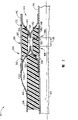
Fig. 3 is the amplification partial section that can be used for pipeline 42 is connected the bracket component 200 on the gas-turbine engine of gas-turbine engine 10 (shown in Figure 1) for example.Fig. 4 is the enlarged perspective of bracket component 200.Bracket component 200 comprises interior piping support assembly 202, outer tube supports part supporting structure 204, outer twister 206 and mounting bracket 208.
Interior piping support assembly 202 comprises a pair of roughly the same interior piping support member 220 and 222 respectively.In the exemplary embodiment, each piping support member 220 and 222 is unimodules of the radially inner side 226 of piping support assembly 202 in extending between the radial outside 224 of interior piping support assembly 202.Can select among the embodiment, each piping support member 220 and 222 is made so that form each support member 220 and 222 by a plurality of drip moldings that link together. Support member 220 and 222 has level and smooth roughly arc section configuration of extending between interior piping support components side 224 and 226.More particularly, each member 220 and 222 has roughly half elliptic cross-sectional configuration.Can select among the embodiment, member 220 and 222 has non-roughly half elliptic section structural member.Can select among the embodiment at another, member 220 and 222 comprises generally flat part and includes only the part elliptic cross-section configuration that is positioned between pipeline 42 and the outer tube supports structure 204.
Therefore, member 220 and 222 does not comprise any turning between interior piping support components side 224 and 226.
Each member 220 and 222 is around pipeline 42 extending circumferentiallies and tube outer surface 80 location that recline.More particularly, member 220 and 222 spaced apart 230 makes to limit gap 232 between member 220 and 222.Gap 232 is therefore also by a part 236 gauges of tube outer surface 80 and outer tube supports structure 204.
Outer tube supports structure 204 makes that around pipeline 42 and interior piping support assembly 202 extending circumferentiallies supporting structure 204 is tube outer surfaces 80 of almost parallel.More particularly, piping support member 220 was connected with 222 in outer tube supports structure 204 reclined, and made outer tube supports structure 204 extend to the radially outward edge 242 of member 222 from the radially outward edge 240 of member 220.In the exemplary embodiment, pipeline 42, member 220 and 222 and outer tube supports structure 204 make by for example metallic material of (but being not limited to) Inco 625.
Ceramic space spare 260 makes gap 262 be limited between the upstream side 264 and ceramic space spare 260 of member 220 around near pipeline 42 extending circumferentiallies the member 220.In another embodiment, ceramic space spare 260 also around near pipeline 42 extending circumferentiallies the member 222, makes the gap (not shown) be limited between the downstream side 268 and ceramic space spare 260 of member 222.Other insulating material 270 extends around recline each side 272 and 274 of ceramic space spare 260 of pipeline 42, makes gap 262 roughly be filled by insulating material 270.Can select among the embodiment, insulating material 270 is also roughly filled the gap of the qualification between ceramic space spare 260 and the member downstream side 268.Can select among the embodiment, insulating material 250 does not use in gap 232, but other ceramic space spare is roughly filled out gram gap 232.
Insulating material 270 and ceramic space spare 260 are covered by twister 206 outside extending on insulating material 270 and ceramic space spare 270 around pipeline 42.In addition, twister 206 extends at least partially on the outer tube supports structure 204, makes the edge 280 of outer tube supports structure 204 and the radially outward edge 240 of interior piping support member be covered by twister 206.In the exemplary embodiment, twister 206 is made by polyimide material, and insulating material 250 and 270 is made by for example same material of (but being not limited to) Min-K insulating material.
In operation, when high temperature fluid passes through pipeline 42, because the interior pipe component 220 and 222 smooth curved of bracket component do not comprise any turning, bracket component 220 helps to reduce the stress that produces in the bracket component 200 that comprises the interior pipe support 50 that has turning 70 and 52 and concentrates.In addition, each pipe component 220 and 222 seamlessly transit and help to reduce stress and concentrate make the structural rigidity of bracket component 200 and structural integrity not incur loss.In addition, owing to compare with other known bracket components 40, bracket component 200 comprises other insulating material 250 and 270, and bracket component 200 helps to reduce by the temperature transfer of mounting bracket to motor 10.In addition, bracket component 200 also uses less components than bracket component 40, and therefore helps to reduce to make and assembly cost.
Described bracket component is saved cost and highly reliable.Each bracket component comprises interior pipe support, and this supporting member comprises between pipe support and the pipeline outside and seamlessly transitting.Therefore, it is concentrated that interior pipe support helps to reduce the stress that produces in the bracket component.In addition, this bracket component comprises other insulating material, and this helps to reduce the heat transmission by this mounting bracket.Therefore, described bracket component helps to prolong with saving cost and reliable mode the working life of high-temperature pipe.
More than describe the exemplary embodiment of bracket component in detail.This assembly is not limited to described specific embodiment, but the parts of each assembly can separate use separately with miscellaneous part.Each bracket component parts also can be used in combination with other bracket component parts.
When the present invention was described in conjunction with different embodiments, those of ordinary skill in the art will appreciate that and can carry out modification in the spirit and scope of claim.
Claims (19)
1. one kind is connected method on the gas-turbine engine housing with pipeline, and described method comprises:
Around this pipeline extending circumferentially first interior piping support member, make this radially inner side of pipe support this pipeline that reclines in first, and wherein have the cross-sectional configuration of general curved between the radial outside of this piping support member pipe support in the radially inner side of this pipe support in first and this first in first;
Around this piping support member extending circumferentially outer tube supports member in first, make the recline outer surface of this piping support member in first of this outer tube supports member; And
This outer tube supports member is connected on this gas-turbine engine housing.
2. the method for claim 1, it is characterized in that, it also comprises piping support member in the pipeline extending circumferentially second, make this in first piping support member be the mirror image of this piping support member in second, and make this limit the gap between piping support member in first and second.
3. method as claimed in claim 2 is characterized in that, it also comprises around at least one insulating material of pipe extension and ceramic space spare, makes at least one insulating material and ceramic space spare roughly fill the gap between the piping support member in first and second.
4. method as claimed in claim 2 is characterized in that it also comprises:
Extend insulating material around the recline inboard and the outside of this piping support member in first of this pipeline;
Make this ceramic space spare insulating material between the piping support member and this ceramic space spare in first that reclines around this pipe extension ceramic space spare;
At least a portion around this ceramic space spare and this outer tube supports member is extended twister.
5. method as claimed in claim 2 is characterized in that, it also comprises mounting bracket is connected on the outer tube supports member.
6. bracket component that is used for pipeline, described bracket component comprises:
The first interior piping support member around this pipeline extending circumferentially, in described first pipe support comprise radial outside, the radially inner side of this pipeline that reclines and extend in main body between this outside and the inboard, described main body has the roughly smooth arc tee section configuration of extending between the described radially inner side and the outside; And
Outer tube supports member around the described first interior piping support member extending circumferentially.
7. bracket component as claimed in claim 6 is characterized in that, described main body has the roughly half elliptic configuration of extending between the described radially inner side and the outside.
8. bracket component as claimed in claim 6, it is characterized in that, it also comprises the second interior pipe support around pipe extension, the mirror image that the described first interior pipe support roughly is a pipe support in described second, and pipe supports separate so that limit the gap betwixt in described first and second.
9. bracket component as claimed in claim 8 is characterized in that at least one insulating material and ceramic space spare are roughly filled described gap.
10. bracket component as claimed in claim 6, it is characterized in that, insulating material extends radially outwardly from pipeline, pipe support comprises internal surface and outer surface in described first, each described internal surface and outer surface radially extend between the described member radially inner side and the outside, the recline interior and outer surface of described first pipe support of described insulating material.
11. bracket component as claimed in claim 10 is characterized in that, it also comprises the ceramic space spare around the pipeline extending circumferentially, and described ceramic space spare is near the insulating material of the inner radial surface of pipe support in the contact described first.
12. bracket component as claimed in claim 11 is characterized in that, it also comprises around the outer twister of at least a portion extending circumferentially of described ceramic space spare and described outer tube supports member.
13. bracket component as claimed in claim 6 is characterized in that, it also comprises and is connected described outer tube supports member so that pipeline is connected structural mounting bracket.
14. a pipeline that is used to comprise the gas-turbine engine of housing, described pipeline comprises:
Be used for the pipe of conveyance fluid therein; And
Be used for described pipe is fixed on bracket component on this motor body, described bracket component is configured to reduce the heat transmission from described pipe to this motor body, described bracket component comprises piping support member and outer tube supports member in first, the piping support member is around described pipe extending circumferentially in described first, make in described first the radially inner side of the piping support member described pipe that reclines, the outer tube supports member is around described interior piping support member extending circumferentially, make the radial outside of the described first support member described outer tube supports member that reclines, the piping support member has the roughly half elliptic cross-sectional configuration of extending between the radially inner side of pipe support in described first and the outside in described first.
15. pipeline as claimed in claim 14, it is characterized in that, described bracket component also comprises the second interior pipe support around described pipe extending circumferentially, pipe support roughly is the mirror image of pipe support in described second in described first, and the described first and described second interior pipe support separates so that limit the gap betwixt.
16. pipeline as claimed in claim 15 is characterized in that, described bracket component also comprises at least one ceramic space spare and insulating material that also roughly is filled in the gap that limits between the piping support members in described first and second around described pipe extending circumferentially.
17. pipeline as claimed in claim 15, it is characterized in that, bracket component also comprises the insulating material around described pipe extending circumferentially, described bracket component first in pipe support between described insulating material, make in described first interior the and outer surface of the pipe support described insulating material that reclines.
18. pipeline as claimed in claim 15 is characterized in that, described bracket component also comprises ceramic space spare and the insulating material around described pipe extending circumferentially, and described insulating material extends between the described ceramic space spare and the described first interior piping support member.
19. pipeline as claimed in claim 15 is characterized in that, the first interior piping support member of described bracket component is configured to help to reduce described bracket component and concentrates for the caused stress of described pipe.
Applications Claiming Priority (2)
| Application Number | Priority Date | Filing Date | Title |
|---|---|---|---|
| US10/251,557 US6715297B1 (en) | 2002-09-20 | 2002-09-20 | Methods and apparatus for supporting high temperature ducting |
| US10/251557 | 2002-09-20 |
Publications (2)
| Publication Number | Publication Date |
|---|---|
| CN1492128A CN1492128A (en) | 2004-04-28 |
| CN100379945C true CN100379945C (en) | 2008-04-09 |
Family
ID=31946477
Family Applications (1)
| Application Number | Title | Priority Date | Filing Date |
|---|---|---|---|
| CNB031586570A Expired - Fee Related CN100379945C (en) | 2002-09-20 | 2003-09-19 | Method and device for support high temperature pipeline |
Country Status (4)
| Country | Link |
|---|---|
| US (1) | US6715297B1 (en) |
| EP (1) | EP1400681A3 (en) |
| JP (1) | JP4471612B2 (en) |
| CN (1) | CN100379945C (en) |
Families Citing this family (9)
| Publication number | Priority date | Publication date | Assignee | Title |
|---|---|---|---|---|
| JP2005163812A (en) * | 2003-11-28 | 2005-06-23 | Nissan Motor Co Ltd | Supporting structure |
| US7197877B2 (en) * | 2004-08-04 | 2007-04-03 | Siemens Power Generation, Inc. | Support system for a pilot nozzle of a turbine engine |
| US7451541B2 (en) * | 2005-02-04 | 2008-11-18 | Pratt & Whitney Canada Corp. | Method of heat shielding an inner tube |
| EP2189630A1 (en) * | 2008-11-19 | 2010-05-26 | Siemens Aktiengesellschaft | Gas turbine, guide vane support for such a gas turbine and gas or steam turbine plant with such a gas turbine |
| US9988155B2 (en) | 2013-02-07 | 2018-06-05 | United Technologies Corporation | System and method for aft mount of gas turbine engine |
| CN103437834B (en) * | 2013-08-30 | 2015-04-08 | 中国化学工程第三建设有限公司 | Stress-free mounting method of flange at inlet steam pipe section of turbine |
| US10436061B2 (en) | 2017-04-13 | 2019-10-08 | General Electric Company | Tapered composite backsheet for use in a turbine engine containment assembly |
| US10677261B2 (en) * | 2017-04-13 | 2020-06-09 | General Electric Company | Turbine engine and containment assembly for use in a turbine engine |
| US10662813B2 (en) | 2017-04-13 | 2020-05-26 | General Electric Company | Turbine engine and containment assembly for use in a turbine engine |
Citations (3)
| Publication number | Priority date | Publication date | Assignee | Title |
|---|---|---|---|---|
| US4415184A (en) * | 1981-04-27 | 1983-11-15 | General Electric Company | High temperature insulated casing |
| US5363312A (en) * | 1990-03-30 | 1994-11-08 | Kabushiki Kaisha Toshiba | Method and apparatus for battery control |
| US6523352B1 (en) * | 1999-08-02 | 2003-02-25 | Tohoku Electric Power Company, Inc. | Piping support of gas turbine steam cooled combustor |
Family Cites Families (28)
| Publication number | Priority date | Publication date | Assignee | Title |
|---|---|---|---|---|
| US96545A (en) | 1869-11-09 | Improvement in faucet-connection | ||
| US398620A (en) | 1889-02-26 | Leslie i | ||
| US520514A (en) | 1894-05-29 | Alexander bryant | ||
| US600988A (en) | 1898-03-22 | Coupling | ||
| US821564A (en) | 1905-09-13 | 1906-05-22 | Modern Improvements Mfg Co | Coupling for pipes and tubes. |
| US1504363A (en) | 1921-01-20 | 1924-08-12 | Madigan Union Corp | Locked coupling |
| US1455971A (en) | 1921-07-21 | 1923-05-22 | Rickenbacker Adolph | Coupling |
| US1589781A (en) | 1925-11-09 | 1926-06-22 | Joseph M Anderson | Rotary tool joint |
| US2109344A (en) | 1937-05-28 | 1938-02-22 | Henry L Selger | Ground joint pipe coupling |
| DE1122469B (en) | 1959-04-24 | 1962-01-25 | Sandvikens Jernverks Ab | Catch sleeve for boring bars u. like |
| US3130747A (en) | 1961-05-15 | 1964-04-28 | Sterer Engineering And Mfg Com | Flow regulator |
| GB1103643A (en) * | 1966-07-22 | 1968-02-21 | Rolls Royce | Gas turbine engine |
| US3449937A (en) | 1967-06-23 | 1969-06-17 | Columbia Summerill Corp | High pressure fuel line heads and the like |
| GB1283953A (en) * | 1969-06-19 | 1972-08-02 | Rolls Royce | Wall for hot fluid streams |
| SE336642B (en) | 1969-10-28 | 1971-07-12 | Astra Meditec Ab | |
| US3838083A (en) | 1972-09-08 | 1974-09-24 | Asahi Glass Co Ltd | Oil-and water-repellent composition of perfluoroalkyl acrylates or methacrylates |
| GB2114694B (en) | 1982-02-11 | 1985-04-11 | Conex Sanbra Limited | Bibcock assemblies |
| JP2789197B2 (en) | 1988-08-19 | 1998-08-20 | 臼井国際産業株式会社 | High-pressure metal pipe having a connection head and a method of forming the head |
| FR2657939B1 (en) | 1990-02-05 | 1992-05-15 | Simmonds Sa | IMPROVED WATERPROOF CONNECTION FOR CONDUITS OF TRANSPORT OF ANY FLUID. |
| US5362110A (en) | 1991-02-25 | 1994-11-08 | Moeller Manufacturing Co., Inc. | Fluid coupling and fastener capture device |
| US5188398A (en) | 1992-01-02 | 1993-02-23 | General Electric Company | Redundantly locked fluid coupling |
| US5263312A (en) | 1992-07-21 | 1993-11-23 | General Electric Company | Tube fitting for a gas turbine engine |
| FR2699644B1 (en) | 1992-12-23 | 1995-01-20 | Snecma | Elastic ring with stress indicator for fitting. |
| US5321205B1 (en) | 1993-01-15 | 1997-02-04 | Thomas & Betts Corp | Electrical connector fitting |
| US5431507A (en) | 1993-07-12 | 1995-07-11 | Smilanick; Steve | Bicycle torque coupling |
| US5369952A (en) * | 1993-07-20 | 1994-12-06 | General Electric Company | Variable friction force damper |
| US5396918A (en) | 1993-11-18 | 1995-03-14 | Agricultural Products, Inc. | Water pressure regulator and method for regulating pressure through a valve |
| US5584511A (en) * | 1995-10-23 | 1996-12-17 | General Electric Company | Multi-degree-of-freedom expansion joint |
-
2002
- 2002-09-20 US US10/251,557 patent/US6715297B1/en not_active Expired - Fee Related
-
2003
- 2003-09-16 EP EP03255787A patent/EP1400681A3/en not_active Withdrawn
- 2003-09-19 CN CNB031586570A patent/CN100379945C/en not_active Expired - Fee Related
- 2003-09-19 JP JP2003327077A patent/JP4471612B2/en not_active Expired - Fee Related
Patent Citations (3)
| Publication number | Priority date | Publication date | Assignee | Title |
|---|---|---|---|---|
| US4415184A (en) * | 1981-04-27 | 1983-11-15 | General Electric Company | High temperature insulated casing |
| US5363312A (en) * | 1990-03-30 | 1994-11-08 | Kabushiki Kaisha Toshiba | Method and apparatus for battery control |
| US6523352B1 (en) * | 1999-08-02 | 2003-02-25 | Tohoku Electric Power Company, Inc. | Piping support of gas turbine steam cooled combustor |
Also Published As
| Publication number | Publication date |
|---|---|
| JP4471612B2 (en) | 2010-06-02 |
| EP1400681A2 (en) | 2004-03-24 |
| US6715297B1 (en) | 2004-04-06 |
| EP1400681A3 (en) | 2006-06-07 |
| US20040055311A1 (en) | 2004-03-25 |
| JP2004116518A (en) | 2004-04-15 |
| CN1492128A (en) | 2004-04-28 |
Similar Documents
| Publication | Publication Date | Title |
|---|---|---|
| US10301960B2 (en) | Shroud assembly for gas turbine engine | |
| US10370986B2 (en) | Nozzle and nozzle assembly for gas turbine engine | |
| JP3947429B2 (en) | Installation of CMC combustion chamber in turbomachine using dilution holes | |
| EP2815980B1 (en) | An accessory mounting for a gas turbine engine | |
| JP4033715B2 (en) | Exhaust frame, gas turbine engine, and manufacturing method thereof | |
| US8141817B2 (en) | Turbojet suspended from an aircraft mast | |
| US7344354B2 (en) | Methods and apparatus for operating gas turbine engines | |
| CA2364768C (en) | Bolted joint for rotor disks and method of reducing thermal gradients therein | |
| US10036276B2 (en) | High durability turbine exhaust case | |
| US20080075590A1 (en) | Gas turbine engine assembly and method of assembling same | |
| EP2809919B1 (en) | Internally cooled spoke | |
| CN100379945C (en) | Method and device for support high temperature pipeline | |
| CA2602322A1 (en) | Gas turbine engine assembly and method of assembling same | |
| US11136995B2 (en) | Pre-diffuser for a gas turbine engine | |
| US11852345B2 (en) | Pre-diffuser for a gas turbine engine | |
| EP3719261A1 (en) | Pre-diffuser for a gas turbine engine | |
| CN108431373B (en) | Turbojet engine with thrust resistance device on the intermediate compressor casing | |
| EP2788585B1 (en) | Gas turbine engine component | |
| JP2017150799A (en) | Combustor assembly |
Legal Events
| Date | Code | Title | Description |
|---|---|---|---|
| C06 | Publication | ||
| PB01 | Publication | ||
| C10 | Entry into substantive examination | ||
| SE01 | Entry into force of request for substantive examination | ||
| C14 | Grant of patent or utility model | ||
| GR01 | Patent grant | ||
| CF01 | Termination of patent right due to non-payment of annual fee | ||
| CF01 | Termination of patent right due to non-payment of annual fee |
Granted publication date: 20080409 Termination date: 20170919 |