EP3211321B1 - Combustor assembly - Google Patents
Combustor assembly Download PDFInfo
- Publication number
- EP3211321B1 EP3211321B1 EP16206147.7A EP16206147A EP3211321B1 EP 3211321 B1 EP3211321 B1 EP 3211321B1 EP 16206147 A EP16206147 A EP 16206147A EP 3211321 B1 EP3211321 B1 EP 3211321B1
- Authority
- EP
- European Patent Office
- Prior art keywords
- liner
- combustor
- assembly
- support member
- combustion chamber
- Prior art date
- Legal status (The legal status is an assumption and is not a legal conclusion. Google has not performed a legal analysis and makes no representation as to the accuracy of the status listed.)
- Active
Links
- 238000002485 combustion reaction Methods 0.000 claims description 98
- 230000008878 coupling Effects 0.000 claims description 37
- 238000010168 coupling process Methods 0.000 claims description 37
- 238000005859 coupling reaction Methods 0.000 claims description 37
- 239000011153 ceramic matrix composite Substances 0.000 claims description 21
- 239000000463 material Substances 0.000 claims description 15
- 239000007769 metal material Substances 0.000 claims description 13
- 239000007789 gas Substances 0.000 description 20
- 230000007704 transition Effects 0.000 description 14
- 239000000567 combustion gas Substances 0.000 description 11
- 230000000712 assembly Effects 0.000 description 10
- 238000000429 assembly Methods 0.000 description 10
- 239000000446 fuel Substances 0.000 description 7
- 238000001816 cooling Methods 0.000 description 5
- 239000012530 fluid Substances 0.000 description 4
- HBMJWWWQQXIZIP-UHFFFAOYSA-N silicon carbide Chemical compound [Si+]#[C-] HBMJWWWQQXIZIP-UHFFFAOYSA-N 0.000 description 4
- 230000008901 benefit Effects 0.000 description 3
- 239000002184 metal Substances 0.000 description 3
- 229910052751 metal Inorganic materials 0.000 description 3
- 229910010271 silicon carbide Inorganic materials 0.000 description 3
- 238000011144 upstream manufacturing Methods 0.000 description 3
- VYPSYNLAJGMNEJ-UHFFFAOYSA-N Silicium dioxide Chemical compound O=[Si]=O VYPSYNLAJGMNEJ-UHFFFAOYSA-N 0.000 description 2
- PNEYBMLMFCGWSK-UHFFFAOYSA-N aluminium oxide Inorganic materials [O-2].[O-2].[O-2].[Al+3].[Al+3] PNEYBMLMFCGWSK-UHFFFAOYSA-N 0.000 description 2
- 229910052799 carbon Inorganic materials 0.000 description 2
- 239000000919 ceramic Substances 0.000 description 2
- 230000008859 change Effects 0.000 description 2
- 239000000835 fiber Substances 0.000 description 2
- 239000011159 matrix material Substances 0.000 description 2
- 230000007246 mechanism Effects 0.000 description 2
- 239000000203 mixture Substances 0.000 description 2
- 230000001141 propulsive effect Effects 0.000 description 2
- OKTJSMMVPCPJKN-UHFFFAOYSA-N Carbon Chemical compound [C] OKTJSMMVPCPJKN-UHFFFAOYSA-N 0.000 description 1
- XUIMIQQOPSSXEZ-UHFFFAOYSA-N Silicon Chemical compound [Si] XUIMIQQOPSSXEZ-UHFFFAOYSA-N 0.000 description 1
- -1 Textron's SCS-6) Chemical compound 0.000 description 1
- INJRKJPEYSAMPD-UHFFFAOYSA-N aluminum;silicic acid;hydrate Chemical compound O.[Al].[Al].O[Si](O)(O)O INJRKJPEYSAMPD-UHFFFAOYSA-N 0.000 description 1
- 230000003466 anti-cipated effect Effects 0.000 description 1
- 230000004888 barrier function Effects 0.000 description 1
- 230000009286 beneficial effect Effects 0.000 description 1
- GUJOJGAPFQRJSV-UHFFFAOYSA-N dialuminum;dioxosilane;oxygen(2-);hydrate Chemical compound O.[O-2].[O-2].[O-2].[Al+3].[Al+3].O=[Si]=O.O=[Si]=O.O=[Si]=O.O=[Si]=O GUJOJGAPFQRJSV-UHFFFAOYSA-N 0.000 description 1
- 238000002347 injection Methods 0.000 description 1
- 239000007924 injection Substances 0.000 description 1
- 239000011256 inorganic filler Substances 0.000 description 1
- 229910003475 inorganic filler Inorganic materials 0.000 description 1
- 239000010443 kyanite Substances 0.000 description 1
- 229910052850 kyanite Inorganic materials 0.000 description 1
- 238000000034 method Methods 0.000 description 1
- 239000010445 mica Substances 0.000 description 1
- 229910052618 mica group Inorganic materials 0.000 description 1
- 229910052901 montmorillonite Inorganic materials 0.000 description 1
- 230000003647 oxidation Effects 0.000 description 1
- 238000007254 oxidation reaction Methods 0.000 description 1
- 239000002245 particle Substances 0.000 description 1
- 230000037361 pathway Effects 0.000 description 1
- 230000002028 premature Effects 0.000 description 1
- 229910052903 pyrophyllite Inorganic materials 0.000 description 1
- 239000012783 reinforcing fiber Substances 0.000 description 1
- 229910052594 sapphire Inorganic materials 0.000 description 1
- 239000010980 sapphire Substances 0.000 description 1
- 150000004760 silicates Chemical class 0.000 description 1
- 229910052710 silicon Inorganic materials 0.000 description 1
- 239000010703 silicon Substances 0.000 description 1
- 239000000377 silicon dioxide Substances 0.000 description 1
- 229910052814 silicon oxide Inorganic materials 0.000 description 1
- 230000003068 static effect Effects 0.000 description 1
- 230000000153 supplemental effect Effects 0.000 description 1
- 239000000454 talc Substances 0.000 description 1
- 229910052623 talc Inorganic materials 0.000 description 1
- 239000010456 wollastonite Substances 0.000 description 1
- 229910052882 wollastonite Inorganic materials 0.000 description 1
Images


Classifications
-
- F—MECHANICAL ENGINEERING; LIGHTING; HEATING; WEAPONS; BLASTING
- F23—COMBUSTION APPARATUS; COMBUSTION PROCESSES
- F23R—GENERATING COMBUSTION PRODUCTS OF HIGH PRESSURE OR HIGH VELOCITY, e.g. GAS-TURBINE COMBUSTION CHAMBERS
- F23R3/00—Continuous combustion chambers using liquid or gaseous fuel
- F23R3/007—Continuous combustion chambers using liquid or gaseous fuel constructed mainly of ceramic components
-
- F—MECHANICAL ENGINEERING; LIGHTING; HEATING; WEAPONS; BLASTING
- F23—COMBUSTION APPARATUS; COMBUSTION PROCESSES
- F23R—GENERATING COMBUSTION PRODUCTS OF HIGH PRESSURE OR HIGH VELOCITY, e.g. GAS-TURBINE COMBUSTION CHAMBERS
- F23R3/00—Continuous combustion chambers using liquid or gaseous fuel
- F23R3/28—Continuous combustion chambers using liquid or gaseous fuel characterised by the fuel supply
- F23R3/286—Continuous combustion chambers using liquid or gaseous fuel characterised by the fuel supply having fuel-air premixing devices
-
- F—MECHANICAL ENGINEERING; LIGHTING; HEATING; WEAPONS; BLASTING
- F02—COMBUSTION ENGINES; HOT-GAS OR COMBUSTION-PRODUCT ENGINE PLANTS
- F02C—GAS-TURBINE PLANTS; AIR INTAKES FOR JET-PROPULSION PLANTS; CONTROLLING FUEL SUPPLY IN AIR-BREATHING JET-PROPULSION PLANTS
- F02C7/00—Features, components parts, details or accessories, not provided for in, or of interest apart form groups F02C1/00 - F02C6/00; Air intakes for jet-propulsion plants
- F02C7/20—Mounting or supporting of plant; Accommodating heat expansion or creep
-
- F—MECHANICAL ENGINEERING; LIGHTING; HEATING; WEAPONS; BLASTING
- F23—COMBUSTION APPARATUS; COMBUSTION PROCESSES
- F23R—GENERATING COMBUSTION PRODUCTS OF HIGH PRESSURE OR HIGH VELOCITY, e.g. GAS-TURBINE COMBUSTION CHAMBERS
- F23R3/00—Continuous combustion chambers using liquid or gaseous fuel
- F23R3/42—Continuous combustion chambers using liquid or gaseous fuel characterised by the arrangement or form of the flame tubes or combustion chambers
- F23R3/50—Combustion chambers comprising an annular flame tube within an annular casing
-
- F—MECHANICAL ENGINEERING; LIGHTING; HEATING; WEAPONS; BLASTING
- F23—COMBUSTION APPARATUS; COMBUSTION PROCESSES
- F23R—GENERATING COMBUSTION PRODUCTS OF HIGH PRESSURE OR HIGH VELOCITY, e.g. GAS-TURBINE COMBUSTION CHAMBERS
- F23R3/00—Continuous combustion chambers using liquid or gaseous fuel
- F23R3/42—Continuous combustion chambers using liquid or gaseous fuel characterised by the arrangement or form of the flame tubes or combustion chambers
- F23R3/60—Support structures; Attaching or mounting means
-
- Y—GENERAL TAGGING OF NEW TECHNOLOGICAL DEVELOPMENTS; GENERAL TAGGING OF CROSS-SECTIONAL TECHNOLOGIES SPANNING OVER SEVERAL SECTIONS OF THE IPC; TECHNICAL SUBJECTS COVERED BY FORMER USPC CROSS-REFERENCE ART COLLECTIONS [XRACs] AND DIGESTS
- Y02—TECHNOLOGIES OR APPLICATIONS FOR MITIGATION OR ADAPTATION AGAINST CLIMATE CHANGE
- Y02T—CLIMATE CHANGE MITIGATION TECHNOLOGIES RELATED TO TRANSPORTATION
- Y02T50/00—Aeronautics or air transport
- Y02T50/60—Efficient propulsion technologies, e.g. for aircraft
Definitions
- the present subject matter relates generally to a gas turbine engine, or more particularly to a combustor assembly for a gas turbine engine.
- a gas turbine engine generally includes a fan and a core arranged in flow communication with one another. Additionally, the core of the gas turbine engine general includes, in serial flow order, a compressor section, a combustion section, a turbine section, and an exhaust section.
- air is provided from the fan to an inlet of the compressor section where one or more axial compressors progressively compress the air until it reaches the combustion section.
- Fuel is mixed with the compressed air and burned within the combustion section to provide combustion gases.
- the combustion gases are routed from the combustion section to the turbine section.
- the flow of combustion gasses through the turbine section drives the turbine section and is then routed through the exhaust section, e.g., to atmosphere.
- non-traditional high temperature materials such as ceramic matrix composite (CMC) materials
- CMC ceramic matrix composite
- typical combustion sections include an inner liner, an outer liner, and a dome.
- the inner and outer liners are being formed of CMC materials, while the dome is formed of a metal material.
- a combustor assembly capable of being mounted within a gas turbine engine in a manner to allow an anticipated amount of thermal expansion of the CMC components would be particularly beneficial.
- a combustor assembly for a gas turbine engine according to claim 1 is provided.
- a gas turbine engine according to claim 9 is provided.
- FIG. 1 is a schematic cross-sectional view of a gas turbine engine in accordance with an exemplary embodiment of the present disclosure. More particularly, for the embodiment of FIG. 1 , the gas turbine engine is a high-bypass turbofan jet engine 10, referred to herein as "turbofan engine 10." As shown in FIG. 1 , the turbofan engine 10 defines an axial direction A (extending parallel to a longitudinal centerline 12 provided for reference), a radial direction R, and a circumferential direction (not shown) extending about the axial direction A. In general, the turbofan 10 includes a fan section 14 and a core turbine engine 16 disposed downstream from the fan section 14.
- the exemplary core turbine engine 16 depicted generally includes a substantially tubular outer casing 18 that defines an annular inlet 20.
- the outer casing 18 encases and the core turbine engine 16 includes, in serial flow relationship, a compressor section including a booster or low pressure (LP) compressor 22 and a high pressure (HP) compressor 24; a combustion section 26; a turbine section including a high pressure (HP) turbine 28 and a low pressure (LP) turbine 30; and a jet exhaust nozzle section 32.
- a high pressure (HP) shaft or spool 34 drivingly connects the HP turbine 28 to the HP compressor 24.
- a low pressure (LP) shaft or spool 36 drivingly connects the LP turbine 30 to the LP compressor 22.
- the compressor section, combustion section 26, turbine section, and nozzle section 32 together define a core air flowpath 37.
- the fan section 14 includes a variable pitch fan 38 having a plurality of fan blades 40 coupled to a disk 42 in a spaced apart manner.
- the fan blades 40 extend outwardly from disk 42 generally along the radial direction R.
- Each fan blade 40 is rotatable relative to the disk 42 about a pitch axis P by virtue of the fan blades 40 being operatively coupled to a suitable pitch change mechanism 44 configured to collectively vary the pitch of the fan blades 40 in unison.
- the fan blades 40, disk 42, and pitch change mechanism 44 are together rotatable about the longitudinal axis 12 by LP shaft 36 across a power gear box 46.
- the power gear box 46 includes a plurality of gears for adjusting the rotational speed of the fan 38 relative to the LP shaft 36 to a more efficient rotational fan speed.
- the disk 42 is covered by a rotatable front hub 48 aerodynamically contoured to promote an airflow through the plurality of fan blades 40.
- the exemplary fan section 14 includes an annular fan casing or outer nacelle 50 that circumferentially surrounds the fan 38 and/or at least a portion of the core turbine engine 16.
- the exemplary nacelle 50 is supported relative to the core turbine engine 16 by a plurality of circumferentially-spaced outlet guide vanes 52.
- a downstream section 54 of the nacelle 50 extends over an outer portion of the core turbine engine 16 so as to define a bypass airflow passage 56 therebetween.
- a volume of air 58 enters the turbofan 10 through an associated inlet 60 of the nacelle 50 and/or fan section 14.
- a first portion of the air 58 as indicated by arrows 62 is directed or routed into the bypass airflow passage 56 and a second portion of the air 58 as indicated by arrow 64 is directed or routed into the core air flowpath 37, or more specifically into the LP compressor 22.
- the ratio between the first portion of air 62 and the second portion of air 64 is commonly known as a bypass ratio.
- the pressure of the second portion of air 64 is then increased as it is routed through the high pressure (HP) compressor 24 and into the combustion section 26, where it is mixed with fuel and burned to provide combustion gases 66.
- HP high pressure
- the combustion gases 66 are routed through the HP turbine 28 where a portion of thermal and/or kinetic energy from the combustion gases 66 is extracted via sequential stages of HP turbine stator vanes 68 that are coupled to the outer casing 18 and HP turbine rotor blades 70 that are coupled to the HP shaft or spool 34, thus causing the HP shaft or spool 34 to rotate, thereby supporting operation of the HP compressor 24.
- the combustion gases 66 are then routed through the LP turbine 30 where a second portion of thermal and kinetic energy is extracted from the combustion gases 66 via sequential stages of LP turbine stator vanes 72 that are coupled to the outer casing 18 and LP turbine rotor blades 74 that are coupled to the LP shaft or spool 36, thus causing the LP shaft or spool 36 to rotate, thereby supporting operation of the LP compressor 22 and/or rotation of the fan 38.
- the combustion gases 66 are subsequently routed through the jet exhaust nozzle section 32 of the core turbine engine 16 to provide propulsive thrust. Simultaneously, the pressure of the first portion of air 62 is substantially increased as the first portion of air 62 is routed through the bypass airflow passage 56 before it is exhausted from a fan nozzle exhaust section 76 of the turbofan 10, also providing propulsive thrust.
- the HP turbine 28, the LP turbine 30, and the jet exhaust nozzle section 32 at least partially define a hot gas path 78 for routing the combustion gases 66 through the core turbine engine 16.
- turbofan engine 10 depicted in FIG. 1 is provided by way of example only, and that in other exemplary embodiments, the turbofan engine 10 may have any other suitable configuration. It should also be appreciated, that in still other exemplary embodiments, aspects of the present disclosure may be incorporated into any other suitable gas turbine engine. For example, in other exemplary embodiments, aspects of the present disclosure may be incorporated into, e.g., a turboprop engine, a turboshaft engine, or a turbojet engine.
- FIG. 2 a side, cross-sectional view is provided of a combustor assembly 100 mounted within the combustion section 26 the turbofan engine 10 of FIG. 1 .
- the combustor assembly 100 is located within the combustion section 26-downstream of the compressor section and upstream of the turbine section.
- the combustor assembly 100 generally defines a plurality of openings 102 at a forward end through which the combustor assembly 100 is configured to receive a flow of compressed air (from the compressor section) and fuel (e.g., from a fuel nozzle 104).
- the fuel and compressed air is mixed using one or more fuel-air injection hardware assemblies 106.
- the mixtures is then provided to a combustion chamber 108 of the combustor assembly 100 wherein such fuel-air mixture is combusted to generate combustion gases.
- Such combustion gases are provided through an outlet 110 of the combustor assembly 100 and into the turbine section for driving the turbine section.
- the combustor assembly 100 generally includes a first combustion chamber member and a second combustion chamber member.
- the first combustion chamber member is configured as a combustor dome 112 and the second combustion chamber member is configured as a combustion chamber liner.
- the combustion chamber liner is configured as a combustion chamber inner liner 114.
- the combustor assembly 100 includes a third combustion chamber member, which for the embodiment depicted is configured as an combustion chamber outer liner 116.
- the combustion chamber outer liner 116 and combustor dome 112 are formed integrally of a single, continuous piece of material.
- the combustion chamber outer liner 116 and combustor dome 112 may instead be formed separately.
- the first and second combustion chamber members i.e., the combustor dome 112 and combustion chamber inner liner 114, as well as the combustion chamber outer liner 116, are each formed of a ceramic matrix composite ("CMC") material.
- CMC material is a non-metallic material having high temperature capability.
- Exemplary CMC materials utilized for the combustor dome 112 and combustion chamber liners may include silicon carbide, silicon, silica or alumina matrix materials and combinations thereof.
- Ceramic fibers may be embedded within the matrix, such as oxidation stable reinforcing fibers including monofilaments like sapphire and silicon carbide (e.g., Textron's SCS-6), as well as rovings and yarn including silicon carbide (e.g., Nippon Carbon's NICALON®, Ube Industries' TYRANNO®, and Dow Coming's SYLRAMIC®), alumina silicates (e.g., Nextel's 440 and 480), and chopped whiskers and fibers (e.g., Nextel's 440 and SAFFIL®), and optionally ceramic particles (e.g., oxides of Si, Al, Zr, Y and combinations thereof) and inorganic fillers (e.g., pyrophyllite, wollastonite, mica, talc, kyanite and montmorillonite).
- oxidation stable reinforcing fibers including monofilaments like sapphire and silicon carbide (e.g., Textron
- the combustor dome 112 (and integrally formed combustion chamber outer liner 116) and combustion chamber inner liner 114 each extend substantially continuously along the circumferential direction C to define an annular shape, as will be more clearly shown in the embodiment of FIG. 3 , discussed below.
- the combustion chamber inner liner 114 is joined to the combustor dome 112, such that the combustion chamber inner liner 114 and the integrally formed combustion chamber outer liner 116 and combustor dome 112 together define an annular combustion chamber 108.
- the exemplary combustor assembly 100 depicted is configured as an annular combustor.
- the combustion chamber outer liner 116 and combustion chamber inner liner 114 each extend generally along the axial direction A-the combustion chamber outer liner 116 extending between a forward end 118 and an aft end 120 and the combustion chamber inner liner 114 similarly extending between a forward end 122 and an aft end 124.
- the combustor dome 112 includes a back wall 126 and a transition portion. Specifically, the combustor dome 112 depicted includes an outer transition portion 128 and an inner transition portion 130.
- the outer transition portion 128 is positioned along an outer edge of the back wall 126 along the radial direction R and the inner transition portion 130 is positioned along an inner edge of the back wall 126 along the radial direction R.
- the inner and outer transition portions 128, 130 each extend circumferentially with the back wall 126 of the combustor dome 112 (see a FIG. 2 ).
- the outer transition portion 128 extends from the back wall 126 towards the outer liner 116 and the inner transition portion 130 extends from the back wall 126 towards the inner liner 114.
- the outer liner 116 is formed integrally with the combustor dome 112 (including the back wall 126 and the outer transition portion 128), and thus the outer transition portion 128 extends seamlessly from the back wall 126 to the outer liner 116.
- the combustor dome 112 and combustion chamber outer liner 116 together define a continuous and seamless surface extending from the combustor dome 112 to the combustion chamber outer liner 116.
- the combustor dome 112 additionally defines an opening 102 and the combustor assembly 100 includes a fuel-air injector hardware assembly 106. More particularly, the combustor dome 112 defines a plurality of openings 102 and the combustor assembly 100 includes a respective plurality of fuel-air injector hardware assemblies 106-each opening 102 configured for receiving a respective one of the plurality of fuel-air injector hardware assemblies 106 (see, e.g., FIG. 3 , below).
- the plurality of fuel-air injector hardware assemblies 106 may each include, e.g., a swirler and/or a baffle. As briefly stated above, the fuel-air injector hardware assemblies 106 are configured to receive a flow of combustible fuel from the fuel nozzle 104 and compressed air from a compressor section of the turbofan engine 10. Each fuel-air injector hardware assembly 106 is attached directly to the combustor dome 112 at a respective one of the plurality of openings 102. Additionally, as is depicted, each fuel-air injector hardware assembly 106 extends into or through such opening 102. More particularly, the combustor dome 112 defines a hot side 132 exposed to the combustion chamber 108 and an opposite cold side 134.
- the exemplary fuel-air injector hardware assemblies 106 are each attached directly to the hot side 132 of the combustor dome 112 and directly to the cold side 134 of the combustor dome 112. As will be more evident in, e.g., FIG. 3 below, for the embodiment depicted each fuel-air injector hardware assembly 106 is attached directly to the combustor dome 112 independently of the other fuel-air injector hardware assemblies 106, or more specifically of the adjacent fuel-air injector hardware assemblies 106. For example, as the combustor dome 112 of the combustor assembly 100 depicted extends continuously along the circumferential direction C, no additional or supplemental supports are required for the combustor dome 112 and plurality of fuel-air injector hardware assemblies 106.
- the combustion chamber inner liner 114 is formed separately from the combustor dome 112 and combustion chamber outer liner 116.
- the combustion chamber inner liner 114 is attached to the combustor dome 112 generally through a mounting assembly 136.
- the first combustion chamber member i.e., the combustor dome 112
- the second combustion chamber member i.e., the combustion chamber inner liner 114
- includes a second coupling flange 140 includes a second coupling flange 140.
- the first and second coupling flanges 138, 140 are positioned adjacent to one another and each extend generally outward from the combustion chamber 108. Specifically, for the embodiment depicted, the first and second coupling flanges 138, 140 extend outwardly generally along the radial direction R.
- the exemplary mounting assembly 136 depicted includes a first mounting flange 142 and a second mounting flange 144.
- the first mounting flange 142 is positioned adjacent to the first coupling flange 138 of the combustor dome 112 and the second mounting flange 144 is positioned adjacent to the second coupling flange 140 of the combustion chamber inner liner 114.
- the mounting assembly 136 further includes an attachment member 146 for pressing the first mounting flange 142 towards the second mounting flange 144 to attach the combustor dome 112 and combustion chamber inner liner 114.
- the attachment member 146 may clamp the first mounting flange 142 and second mounting flange 144 together to attach the combustor dome 112 and combustion chamber outer liner 114.
- the mounting assembly 136 is attached to the combustion chamber outer liner 116 and the combustor dome 112. More specifically, for the embodiment depicted the mounting assembly 136 is attached to the combustion chamber inner liner 114 proximate the forward end 122 of the combustion chamber inner liner 114 for supporting the combustor dome 112 and combustion chamber inner liner 114 within the turbofan engine 10 relative to a structural component of the turbofan engine 10.
- the exemplary mounting assembly 136 depicted includes a support member 148 defining a length 149 extending from a forward end 150 to an aft end 152 generally along the axial direction A.
- the forward end 150 of the support member 148 includes the second mounting flange 144 and, as stated and as will be discussed in further detail below, is attached to the combustion chamber inner liner 114 proximate the forward end 122 of the combustion chamber inner liner 114.
- the term "proximate the forward end” may refer to generally to a location closer to a forward end than an aft end. Accordingly, for example, the combustor assembly 100 may define a length 154 generally along the axial direction A between one or more of the openings 102 and the outlet 110 to the turbine section.
- the mounting assembly 136 may be attached to the combustion chamber inner liner 114 within at least about the forward 50% of the combustor assembly length 154.
- the mounting assembly 136 may be attached to the combustion chamber inner liner 114 within at least about the forward 40% of the combustor assembly length 154, within at least about the forward 30% of the combustor assembly length 154, or within at least about the forward 20% of the combustor assembly length 154. It should be appreciated, that as used herein, terms of approximation, such as “about” or “approximately,” refer to being within a 10% margin of error.
- the mounting assembly 136 is configured for supporting the combustor dome 112, the combustion chamber inner liner 114, and the combustion chamber outer liner 116 within the turbofan engine 10.
- the exemplary support member 148 is configured for attachment to a structural component of the turbofan engine 10 at the aft end 152. More particularly, the support member 148 includes an attachment flange 156 through which the support member 148 is attached to the structural component of the turbofan engine 10 to support the combustor assembly 100.
- the structural component is configured as a turbine frame 158 at least partially defining a flowpath through the turbine section.
- the structural component may be any static structural member within the turbofan engine 10.
- the structural component may be an inner compressor casing 160, an outer compressor casing 162, a turbine casing 164, etc.
- the mounting assembly 136 may be formed of a metal material. More particularly, the support member 148, including the second coupling flange 140, and the first coupling flange 138 may each be formed of a metal material. Such a configuration may allow for a desired amount of thermal growth during operation of the turbofan engine 10. More particularly, as the combustion chamber inner and outer liners 114, 116 and combustor dome 112 are all supported through the mounting assembly 136 at forward end 122 of the combustion chamber inner liner 114, a distance between the fuel-air injector hardware assembly 106 and an inlet to the turbine section will be dictated substantially by an amount of thermal growth of the mounting assembly 136.
- the various other components surrounding the combustor assembly 100 such as the inner and outer compressor casings 160, 162 and turbine casing 164, are all also formed of a metal material, the thermal growth of the mounting assembly 136 will likely match a thermal growth of such components and ensure the combustor assembly 100 is in a desired location within the turbofan engine 10, despite a mismatched thermal growth between the CMC components of the combustor assembly 100 and the mounting assembly 136.
- FIGS. 3 through 5 various views of a combustor assembly 100 in accordance with an exemplary embodiment of the present disclosure are provided.
- the exemplary combustor assembly 100 of FIGS. 3 through 5 may be configured in substantially the same manner as exemplary combustor assembly 100 of FIG. 2 , and accordingly, the same or similar numbering may refer to the same or similar parts.
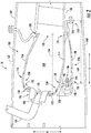
- FIG. 3 provides a perspective view of an assembled combustor assembly 100
- FIG. 4 provides a perspective, cross-sectional view of a section of the exemplary combustor assembly 100 of FIG. 3
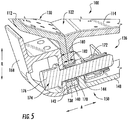
- FIG. 5 provides a close-up, cross-sectional view of an attachment portion of a mounting assembly 136 of the exemplary combustor assembly 100 of FIG. 3 .
- the combustor assembly 100 includes a plurality of cooling holes 166 extending through one or more of the combustion chamber members to allow a flow of cooling air therethrough.
- the exemplary combustor assembly 100 depicted includes a plurality of cooling holes 166 extending through the combustion chamber outer liner 116, the combustion chamber inner liner 114, and the combustor dome 112 to allow for an amount of cooling air to flow therethrough.
- the cooling air may be provided from a compressor section of a gas turbine engine into which the combustor assembly 100 is installed.
- the combustor assembly 100 is generally configured as an annular combustor. Accordingly, the combustion chamber outer liner 116, the combustor dome 112 (formed integrally with the combustion chamber outer liner 116 for the embodiment depicted), and combustion chamber inner liner 114 (see, e.g., FIG. 4 ) each extend substantially continuously along the circumferential direction C to define an annular shape. Although not depicted in FIG. 3 , the first coupling flange 138 (of the combustor dome 112) and the second coupling flange 140 (of the combustion chamber inner liner 114) also extend substantially continuously in the circumferential direction.
- the mounting assembly 136 and more particularly, the first mounting flange 142 and the support member 148, including the second mounting flange 144, each also extend substantially continuously along the circumferential direction C to define an annular shape.
- the support member 148 may be referred to as an annular support member 148.
- the first mounting flange 142 is formed of a plurality of individual mounting brackets 168 circumferentially arranged adjacent to one another.
- the mounting assembly 136 is formed generally of a metal material, as compared to the combustion chamber inner liner 114, combustor dome 112, and combustion chamber outer liner 116, which may each be formed of a CMC material. Accordingly, the mounting brackets 168 forming the first mounting flange 142 of the mounting assembly 136 are formed of metal material, as is the support member 148, including the second mounting flange 144. In order to accommodate a mismatch in coefficients of thermal expansion, the support member 148 includes a plurality of gaps 170 extending generally along the axial direction A. However, in other embodiments, the plurality of gaps 170 may instead extend in any other suitable direction. Notably, inclusion of the plurality of gaps 170 may additionally provide vibration dampening and other benefits to the combustor assembly 100.
- each gap 170 depicted each extend along at least about fifty percent of the length 149 of the support member 148. Specifically for the embodiment depicted, each of the plurality of gaps 170 extend along at least about sixty percent of the length 149 of the support member 148. Further, each gap 170 in the plurality of gaps 170 defines a width 171 ( FIG. 3 ). As the gaps 170 depicted extend generally along the axial direction A, the width 171 is defined generally along the circumferential direction C. The width 171 of each gap 170 may be at least about 0.05 inches, at least about 0.10 inches, at least about 0.20 inches, or any other suitable width.
- the gaps 170 allow for relative expansion of at least one of the combustion chamber outer liner 116 or combustor dome 112 relative to the support member 148 of the mounting assembly 136. More particularly, the gaps 170 allow for relative expansion of each of the CMC components, i.e., the combustion chamber inner liner 114, the combustor dome 112, and combustion chamber outer liner 116, relative to the support member 148 of the mounting assembly 136 generally along the radial direction R.
- the exemplary attachment member 146 is configured as a nut 172 and bolt 174, or rather a plurality of nuts 172 and bolts 174, each bolt 174 extending through the first and second mounting flanges 142, 144 as well as the first and second coupling flanges 138, 140.
- the bolts 174 each include a head 176 pressing against the first mounting flange 142, and each of the respective nuts 172 are threadably engaged with the respective bolt 174, pressing against the second mounting flange 144.
- the force attaching the first and second coupling flanges 138, 140 of the combustor dome 112 and combustion chamber inner liner 114, respectively, is distributed amongst an inner surface area of the first mounting flange 142 and of the second mounting flange 144. Accordingly, the first and second coupling flanges 138, 140 are pressed together with a minimal amount of point force applied thereto. Such a configuration may limit damage to the first and second coupling flanges 138, 140.
- the mounting assembly 136 further includes a bushing 178, or rather a plurality of bushings 178, each bushing 178 extending around the respective bolt 174 within the first and second coupling flanges 138, 140.
- the bushings 178 may act as a barrier between the bolts 174 (formed of a metal material) and the first and second coupling flanges 138, 140 (formed of CMC materials). Accordingly, any wear on the metal materials from the CMC materials will be absorbed by the bushings 178 as opposed to the bolts 174.
- first and second coupling flanges 138, 140 together define a combined width 180 and each of the bushings similarly define a length 182.
- the length 182 of each of the bushings 178 is less than the combined width 180 of the first and second coupling flanges 138, 140 to allow for relative thermal expansions between the bushing 178, which may be formed of a metal material, and the first and second coupling flanges 138, 140.
- first mounting flange 142 may allow for a more durable attachment of the combustor dome 112 to the combustion chamber inner liner 114. More specifically, inclusion of such metal components between the metal bolt 174 and the CMC dome 112 and inner liner 114 may reduce a risk of premature wear to the bolt 174 during operation of the combustor assembly 100.
- the exemplary combustor assembly 100 described herein is provided by way of example only and that in other exemplary embodiments of the present disclosure, the combustor assembly 100 may have any other suitable configuration.
- the combustion chamber outer liner 116 may not be formed integrally with the combustor dome 112, and instead may be attached to the combustor dome 112 in any suitable manner.
- the combustion chamber inner liner 114 may be integrally formed with the combustor dome 112 instead of or in addition to the combustion chamber outer liner 116.
- the combustor dome 112 may have any other suitable configuration.
- the combustor dome 112 may not include one or both of the outer transition portion 128 or the inner transition portion 130.
- one or both of the outer transition portion 128 or the inner transition portion 130 may be configured in any other suitable manner.
- the mounting assembly 136 is located generally at a radially inner location of the combustor assembly 100, in other embodiments, the mounting assembly 136 may instead be located at a radially outer location.
- the mounting assembly 136 may be configured to attach a combustion chamber outer liner 116 to a separately formed combustion chamber 108 dome.
- the mounting assembly 136 attaches to the combustion chamber liner and dome at a forward end of the combustion chamber liner, in other embodiments, the mounting assembly 136 may instead attach to, e.g., a combustion chamber liner at an aft end of the combustion chamber liner, or any other suitable location.
- the mounting assembly 136 including the support member 148, may extend forward from the coupling flanges 138, 140 (as opposed to extending aft as in the embodiments depicted) to a support member within the gas turbine engine located forward of the coupling flanges 138, 140.
- the various components defining the combustion chamber 108 extend substantially continuously along the circumferential direction C to define an annular shape, in other exemplary embodiments, such components may instead include a plurality of components spaced along the circumferential direction C to define the combustion chamber 108.
- the combustor assembly 100 may have any other suitable fuel-air injector hardware assemblies 106 mounted to the combustor dome 112 in any other suitable manner.
Description
- The present subject matter relates generally to a gas turbine engine, or more particularly to a combustor assembly for a gas turbine engine.
- A gas turbine engine generally includes a fan and a core arranged in flow communication with one another. Additionally, the core of the gas turbine engine general includes, in serial flow order, a compressor section, a combustion section, a turbine section, and an exhaust section. In operation, air is provided from the fan to an inlet of the compressor section where one or more axial compressors progressively compress the air until it reaches the combustion section. Fuel is mixed with the compressed air and burned within the combustion section to provide combustion gases. The combustion gases are routed from the combustion section to the turbine section. The flow of combustion gasses through the turbine section drives the turbine section and is then routed through the exhaust section, e.g., to atmosphere.
- More commonly, non-traditional high temperature materials, such as ceramic matrix composite (CMC) materials, are being used as structural components within gas turbine engines. For example, given an ability for CMC materials to withstand relatively extreme temperatures, there is particular interest in replacing components within the combustion section of the gas turbine engine with CMC materials. For example, typical combustion sections include an inner liner, an outer liner, and a dome. More commonly, the inner and outer liners are being formed of CMC materials, while the dome is formed of a metal material.
- However, certain gas turbine engines have had problems accommodating certain mechanical properties of the CMC materials incorporated therein. For example, CMC materials have different coefficients of thermal expansion than the traditional metal materials. Therefore, the attachment of the inner and outer CMC liners to the metal dome may require a fairly complicated attachment assembly. Additionally, such a configuration may complicate mounting of the combustor assembly within the gas turbine engine, given that a majority of the components surrounding the combustor assembly are formed of a metal material. Document
US6668559 discloses a combustor assembly for a gas turbine engine according to prior art.. - Accordingly, a combustor assembly capable of being mounted within a gas turbine engine in a manner to allow an anticipated amount of thermal expansion of the CMC components would be particularly beneficial.
- Aspects and advantages of the invention will be set forth in part in the following description, or may be obvious from the description, or may be learned through practice of the invention.
- In one exemplary embodiment of the present disclosure, a combustor assembly for a gas turbine engine according to claim 1 is provided.
- In another exemplary embodiment of the present disclosure, a gas turbine engine according to claim 9 is provided.
- These and other features, aspects and advantages of the present invention will become better understood with reference to the following description and appended claims. The accompanying drawings, which are incorporated in and constitute a part of this specification, illustrate embodiments of the invention and, together with the description, serve to explain the principles of the invention.
- A full and enabling disclosure of the present invention, including the best mode thereof, directed to one of ordinary skill in the art, is set forth in the specification, which makes reference to the appended figures, in which:
-
FIG. 1 is a schematic cross-sectional view of an exemplary gas turbine engine according to various embodiments of the present subject matter. -
FIG. 2 is a side, sectional view of a combustor assembly in accordance with an exemplary embodiment of the present disclosure positioned in a combustion section of the exemplary gas turbine engine ofFIG. 1 . -
FIG. 3 is a perspective view of a combustor assembly in accordance with another exemplary embodiment of the present disclosure. -
FIG. 4 is a perspective, cross-sectional view of a section of the exemplary combustor assembly ofFIG. 3 . -
FIG. 5 is a close-up, perspective, cross-sectional view of an attachment portion of the exemplary combustor assembly ofFIG. 3 . - Reference will now be made in detail to present embodiments of the invention, one or more examples of which are illustrated in the accompanying drawings. The detailed description uses numerical and letter designations to refer to features in the drawings. Like or similar designations in the drawings and description have been used to refer to like or similar parts of the invention. As used herein, the terms "first", "second", and "third" may be used interchangeably to distinguish one component from another and are not intended to signify location or importance of the individual components. The terms "upstream" and "downstream" refer to the relative direction with respect to fluid flow in a fluid pathway. For example, "upstream" refers to the direction from which the fluid flows, and "downstream" refers to the direction to which the fluid flows.
- Referring now to the drawings, wherein identical numerals indicate the same elements throughout the figures,
FIG. 1 is a schematic cross-sectional view of a gas turbine engine in accordance with an exemplary embodiment of the present disclosure. More particularly, for the embodiment ofFIG. 1 , the gas turbine engine is a high-bypassturbofan jet engine 10, referred to herein as "turbofan engine 10." As shown inFIG. 1 , theturbofan engine 10 defines an axial direction A (extending parallel to alongitudinal centerline 12 provided for reference), a radial direction R, and a circumferential direction (not shown) extending about the axial direction A. In general, theturbofan 10 includes afan section 14 and acore turbine engine 16 disposed downstream from thefan section 14. - The exemplary
core turbine engine 16 depicted generally includes a substantially tubularouter casing 18 that defines anannular inlet 20. Theouter casing 18 encases and thecore turbine engine 16 includes, in serial flow relationship, a compressor section including a booster or low pressure (LP)compressor 22 and a high pressure (HP)compressor 24; acombustion section 26; a turbine section including a high pressure (HP)turbine 28 and a low pressure (LP)turbine 30; and a jetexhaust nozzle section 32. A high pressure (HP) shaft orspool 34 drivingly connects the HPturbine 28 to the HPcompressor 24. A low pressure (LP) shaft orspool 36 drivingly connects theLP turbine 30 to theLP compressor 22. The compressor section,combustion section 26, turbine section, andnozzle section 32 together define acore air flowpath 37. - For the embodiment depicted, the
fan section 14 includes avariable pitch fan 38 having a plurality offan blades 40 coupled to adisk 42 in a spaced apart manner. As depicted, thefan blades 40 extend outwardly fromdisk 42 generally along the radial direction R. Eachfan blade 40 is rotatable relative to thedisk 42 about a pitch axis P by virtue of thefan blades 40 being operatively coupled to a suitablepitch change mechanism 44 configured to collectively vary the pitch of thefan blades 40 in unison. Thefan blades 40,disk 42, andpitch change mechanism 44 are together rotatable about thelongitudinal axis 12 byLP shaft 36 across apower gear box 46. Thepower gear box 46 includes a plurality of gears for adjusting the rotational speed of thefan 38 relative to theLP shaft 36 to a more efficient rotational fan speed. - Referring still to the exemplary embodiment of
FIG. 1 , thedisk 42 is covered by arotatable front hub 48 aerodynamically contoured to promote an airflow through the plurality offan blades 40. Additionally, theexemplary fan section 14 includes an annular fan casing orouter nacelle 50 that circumferentially surrounds thefan 38 and/or at least a portion of thecore turbine engine 16. Theexemplary nacelle 50 is supported relative to thecore turbine engine 16 by a plurality of circumferentially-spacedoutlet guide vanes 52. Moreover, adownstream section 54 of thenacelle 50 extends over an outer portion of thecore turbine engine 16 so as to define abypass airflow passage 56 therebetween. - During operation of the
turbofan engine 10, a volume ofair 58 enters theturbofan 10 through an associatedinlet 60 of thenacelle 50 and/orfan section 14. As the volume ofair 58 passes across thefan blades 40, a first portion of theair 58 as indicated byarrows 62 is directed or routed into thebypass airflow passage 56 and a second portion of theair 58 as indicated byarrow 64 is directed or routed into thecore air flowpath 37, or more specifically into theLP compressor 22. The ratio between the first portion ofair 62 and the second portion ofair 64 is commonly known as a bypass ratio. The pressure of the second portion ofair 64 is then increased as it is routed through the high pressure (HP)compressor 24 and into thecombustion section 26, where it is mixed with fuel and burned to provide combustion gases 66. - The combustion gases 66 are routed through the HP
turbine 28 where a portion of thermal and/or kinetic energy from the combustion gases 66 is extracted via sequential stages of HP turbine stator vanes 68 that are coupled to theouter casing 18 and HPturbine rotor blades 70 that are coupled to the HP shaft orspool 34, thus causing the HP shaft orspool 34 to rotate, thereby supporting operation of the HPcompressor 24. The combustion gases 66 are then routed through theLP turbine 30 where a second portion of thermal and kinetic energy is extracted from the combustion gases 66 via sequential stages of LPturbine stator vanes 72 that are coupled to theouter casing 18 and LPturbine rotor blades 74 that are coupled to the LP shaft orspool 36, thus causing the LP shaft orspool 36 to rotate, thereby supporting operation of theLP compressor 22 and/or rotation of thefan 38. - The combustion gases 66 are subsequently routed through the jet
exhaust nozzle section 32 of thecore turbine engine 16 to provide propulsive thrust. Simultaneously, the pressure of the first portion ofair 62 is substantially increased as the first portion ofair 62 is routed through thebypass airflow passage 56 before it is exhausted from a fannozzle exhaust section 76 of theturbofan 10, also providing propulsive thrust. The HPturbine 28, theLP turbine 30, and the jetexhaust nozzle section 32 at least partially define ahot gas path 78 for routing the combustion gases 66 through thecore turbine engine 16. - It should be appreciated, however, that the
exemplary turbofan engine 10 depicted inFIG. 1 is provided by way of example only, and that in other exemplary embodiments, theturbofan engine 10 may have any other suitable configuration. It should also be appreciated, that in still other exemplary embodiments, aspects of the present disclosure may be incorporated into any other suitable gas turbine engine. For example, in other exemplary embodiments, aspects of the present disclosure may be incorporated into, e.g., a turboprop engine, a turboshaft engine, or a turbojet engine. - Referring now to
FIG. 2 , a side, cross-sectional view is provided of acombustor assembly 100 mounted within thecombustion section 26 theturbofan engine 10 ofFIG. 1 . As shown, thecombustor assembly 100 is located within the combustion section 26-downstream of the compressor section and upstream of the turbine section. As will be discussed in greater detail below, thecombustor assembly 100 generally defines a plurality ofopenings 102 at a forward end through which thecombustor assembly 100 is configured to receive a flow of compressed air (from the compressor section) and fuel (e.g., from a fuel nozzle 104). The fuel and compressed air is mixed using one or more fuel-airinjection hardware assemblies 106. The mixtures is then provided to acombustion chamber 108 of thecombustor assembly 100 wherein such fuel-air mixture is combusted to generate combustion gases. Such combustion gases are provided through anoutlet 110 of thecombustor assembly 100 and into the turbine section for driving the turbine section. - The
combustor assembly 100 generally includes a first combustion chamber member and a second combustion chamber member. For the embodiment depicted, the first combustion chamber member is configured as acombustor dome 112 and the second combustion chamber member is configured as a combustion chamber liner. Specifically for the embodiment depicted, the combustion chamber liner is configured as a combustion chamberinner liner 114. Additionally, thecombustor assembly 100 includes a third combustion chamber member, which for the embodiment depicted is configured as an combustion chamberouter liner 116. Notably, for the exemplary embodiment depicted, the combustion chamberouter liner 116 andcombustor dome 112 are formed integrally of a single, continuous piece of material. However, in other embodiments, the combustion chamberouter liner 116 andcombustor dome 112 may instead be formed separately. - Referring still to
FIG. 2 , the first and second combustion chamber members, i.e., thecombustor dome 112 and combustion chamberinner liner 114, as well as the combustion chamberouter liner 116, are each formed of a ceramic matrix composite ("CMC") material. CMC material is a non-metallic material having high temperature capability. Exemplary CMC materials utilized for thecombustor dome 112 and combustion chamber liners (e.g., theinner liner 114 and outer liner 116) may include silicon carbide, silicon, silica or alumina matrix materials and combinations thereof. Ceramic fibers may be embedded within the matrix, such as oxidation stable reinforcing fibers including monofilaments like sapphire and silicon carbide (e.g., Textron's SCS-6), as well as rovings and yarn including silicon carbide (e.g., Nippon Carbon's NICALON®, Ube Industries' TYRANNO®, and Dow Coming's SYLRAMIC®), alumina silicates (e.g., Nextel's 440 and 480), and chopped whiskers and fibers (e.g., Nextel's 440 and SAFFIL®), and optionally ceramic particles (e.g., oxides of Si, Al, Zr, Y and combinations thereof) and inorganic fillers (e.g., pyrophyllite, wollastonite, mica, talc, kyanite and montmorillonite). - Additionally, the combustor dome 112 (and integrally formed combustion chamber outer liner 116) and combustion chamber
inner liner 114 each extend substantially continuously along the circumferential direction C to define an annular shape, as will be more clearly shown in the embodiment ofFIG. 3 , discussed below. As will also be discussed in greater detail below, the combustion chamberinner liner 114 is joined to thecombustor dome 112, such that the combustion chamberinner liner 114 and the integrally formed combustion chamberouter liner 116 andcombustor dome 112 together define anannular combustion chamber 108. Accordingly, theexemplary combustor assembly 100 depicted is configured as an annular combustor. - Referring still to
FIG. 2 , the combustion chamberouter liner 116 and combustion chamberinner liner 114 each extend generally along the axial direction A-the combustion chamberouter liner 116 extending between aforward end 118 and anaft end 120 and the combustion chamberinner liner 114 similarly extending between aforward end 122 and anaft end 124. Additionally, thecombustor dome 112 includes aback wall 126 and a transition portion. Specifically, thecombustor dome 112 depicted includes anouter transition portion 128 and aninner transition portion 130. Theouter transition portion 128 is positioned along an outer edge of theback wall 126 along the radial direction R and theinner transition portion 130 is positioned along an inner edge of theback wall 126 along the radial direction R. The inner andouter transition portions back wall 126 of the combustor dome 112 (see aFIG. 2 ). - The
outer transition portion 128 extends from theback wall 126 towards theouter liner 116 and theinner transition portion 130 extends from theback wall 126 towards theinner liner 114. As stated, for the embodiment depicted theouter liner 116 is formed integrally with the combustor dome 112 (including theback wall 126 and the outer transition portion 128), and thus theouter transition portion 128 extends seamlessly from theback wall 126 to theouter liner 116. For example, thecombustor dome 112 and combustion chamberouter liner 116 together define a continuous and seamless surface extending from thecombustor dome 112 to the combustion chamberouter liner 116. - Referring still to
FIG. 2 , and as briefly stated above, thecombustor dome 112 additionally defines anopening 102 and thecombustor assembly 100 includes a fuel-airinjector hardware assembly 106. More particularly, thecombustor dome 112 defines a plurality ofopenings 102 and thecombustor assembly 100 includes a respective plurality of fuel-air injector hardware assemblies 106-eachopening 102 configured for receiving a respective one of the plurality of fuel-air injector hardware assemblies 106 (see, e.g.,FIG. 3 , below). - The plurality of fuel-air
injector hardware assemblies 106 may each include, e.g., a swirler and/or a baffle. As briefly stated above, the fuel-airinjector hardware assemblies 106 are configured to receive a flow of combustible fuel from thefuel nozzle 104 and compressed air from a compressor section of theturbofan engine 10. Each fuel-airinjector hardware assembly 106 is attached directly to thecombustor dome 112 at a respective one of the plurality ofopenings 102. Additionally, as is depicted, each fuel-airinjector hardware assembly 106 extends into or throughsuch opening 102. More particularly, thecombustor dome 112 defines ahot side 132 exposed to thecombustion chamber 108 and an oppositecold side 134. The exemplary fuel-airinjector hardware assemblies 106 are each attached directly to thehot side 132 of thecombustor dome 112 and directly to thecold side 134 of thecombustor dome 112. As will be more evident in, e.g.,FIG. 3 below, for the embodiment depicted each fuel-airinjector hardware assembly 106 is attached directly to thecombustor dome 112 independently of the other fuel-airinjector hardware assemblies 106, or more specifically of the adjacent fuel-airinjector hardware assemblies 106. For example, as thecombustor dome 112 of thecombustor assembly 100 depicted extends continuously along the circumferential direction C, no additional or supplemental supports are required for thecombustor dome 112 and plurality of fuel-airinjector hardware assemblies 106. - Referring still to
FIG. 2 , by contrast to the integrally formed combustion chamberouter liner 116 andcombustor dome 112, for the embodiment depicted the combustion chamberinner liner 114 is formed separately from thecombustor dome 112 and combustion chamberouter liner 116. The combustion chamberinner liner 114 is attached to thecombustor dome 112 generally through a mountingassembly 136. Specifically, the first combustion chamber member, i.e., thecombustor dome 112, includes afirst coupling flange 138 and the second combustion chamber member, i.e., the combustion chamberinner liner 114, includes asecond coupling flange 140. The first andsecond coupling flanges combustion chamber 108. Specifically, for the embodiment depicted, the first andsecond coupling flanges - Moreover, the exemplary mounting
assembly 136 depicted includes a first mountingflange 142 and asecond mounting flange 144. Thefirst mounting flange 142 is positioned adjacent to thefirst coupling flange 138 of thecombustor dome 112 and the second mountingflange 144 is positioned adjacent to thesecond coupling flange 140 of the combustion chamberinner liner 114. Moreover, the mountingassembly 136 further includes anattachment member 146 for pressing the first mountingflange 142 towards the second mountingflange 144 to attach thecombustor dome 112 and combustion chamberinner liner 114. For example, theattachment member 146 may clamp the first mountingflange 142 and second mountingflange 144 together to attach thecombustor dome 112 and combustion chamberouter liner 114. - Accordingly, the mounting
assembly 136 is attached to the combustion chamberouter liner 116 and thecombustor dome 112. More specifically, for the embodiment depicted the mountingassembly 136 is attached to the combustion chamberinner liner 114 proximate theforward end 122 of the combustion chamberinner liner 114 for supporting thecombustor dome 112 and combustion chamberinner liner 114 within theturbofan engine 10 relative to a structural component of theturbofan engine 10. For example, the exemplary mountingassembly 136 depicted includes asupport member 148 defining alength 149 extending from aforward end 150 to anaft end 152 generally along the axial direction A. Theforward end 150 of thesupport member 148 includes the second mountingflange 144 and, as stated and as will be discussed in further detail below, is attached to the combustion chamberinner liner 114 proximate theforward end 122 of the combustion chamberinner liner 114. - As used herein, the term "proximate the forward end" may refer to generally to a location closer to a forward end than an aft end. Accordingly, for example, the
combustor assembly 100 may define alength 154 generally along the axial direction A between one or more of theopenings 102 and theoutlet 110 to the turbine section. The mountingassembly 136 may be attached to the combustion chamberinner liner 114 within at least about the forward 50% of thecombustor assembly length 154. More particularly, for the embodiment depicted, the mountingassembly 136 may be attached to the combustion chamberinner liner 114 within at least about the forward 40% of thecombustor assembly length 154, within at least about the forward 30% of thecombustor assembly length 154, or within at least about the forward 20% of thecombustor assembly length 154. It should be appreciated, that as used herein, terms of approximation, such as "about" or "approximately," refer to being within a 10% margin of error. - As stated, the mounting
assembly 136 is configured for supporting thecombustor dome 112, the combustion chamberinner liner 114, and the combustion chamberouter liner 116 within theturbofan engine 10. Specifically, theexemplary support member 148 is configured for attachment to a structural component of theturbofan engine 10 at theaft end 152. More particularly, thesupport member 148 includes anattachment flange 156 through which thesupport member 148 is attached to the structural component of theturbofan engine 10 to support thecombustor assembly 100. For the embodiment depicted, the structural component is configured as aturbine frame 158 at least partially defining a flowpath through the turbine section. However, in other embodiments, the structural component may be any static structural member within theturbofan engine 10. For example, in other embodiments, the structural component may be aninner compressor casing 160, anouter compressor casing 162, aturbine casing 164, etc. - As will be discussed in greater detail below with reference to the exemplary embodiment of
FIGS. 3 through 5 , the mountingassembly 136 may be formed of a metal material. More particularly, thesupport member 148, including thesecond coupling flange 140, and thefirst coupling flange 138 may each be formed of a metal material. Such a configuration may allow for a desired amount of thermal growth during operation of theturbofan engine 10. More particularly, as the combustion chamber inner andouter liners combustor dome 112 are all supported through the mountingassembly 136 atforward end 122 of the combustion chamberinner liner 114, a distance between the fuel-airinjector hardware assembly 106 and an inlet to the turbine section will be dictated substantially by an amount of thermal growth of the mountingassembly 136. Further, as the various other components surrounding thecombustor assembly 100, such as the inner andouter compressor casings turbine casing 164, are all also formed of a metal material, the thermal growth of the mountingassembly 136 will likely match a thermal growth of such components and ensure thecombustor assembly 100 is in a desired location within theturbofan engine 10, despite a mismatched thermal growth between the CMC components of thecombustor assembly 100 and the mountingassembly 136. - Referring now to
FIGS. 3 through 5 , various views of acombustor assembly 100 in accordance with an exemplary embodiment of the present disclosure are provided. Theexemplary combustor assembly 100 ofFIGS. 3 through 5 may be configured in substantially the same manner asexemplary combustor assembly 100 ofFIG. 2 , and accordingly, the same or similar numbering may refer to the same or similar parts. Specifically,FIG. 3 provides a perspective view of an assembledcombustor assembly 100;FIG. 4 provides a perspective, cross-sectional view of a section of theexemplary combustor assembly 100 ofFIG. 3 ; andFIG. 5 provides a close-up, cross-sectional view of an attachment portion of a mountingassembly 136 of theexemplary combustor assembly 100 ofFIG. 3 . - As may be seen most clearly in
FIG. 3 , thecombustor assembly 100 includes a plurality ofcooling holes 166 extending through one or more of the combustion chamber members to allow a flow of cooling air therethrough. Specifically, theexemplary combustor assembly 100 depicted includes a plurality ofcooling holes 166 extending through the combustion chamberouter liner 116, the combustion chamberinner liner 114, and thecombustor dome 112 to allow for an amount of cooling air to flow therethrough. The cooling air may be provided from a compressor section of a gas turbine engine into which thecombustor assembly 100 is installed. - As previously stated, the
combustor assembly 100 is generally configured as an annular combustor. Accordingly, the combustion chamberouter liner 116, the combustor dome 112 (formed integrally with the combustion chamberouter liner 116 for the embodiment depicted), and combustion chamber inner liner 114 (see, e.g.,FIG. 4 ) each extend substantially continuously along the circumferential direction C to define an annular shape. Although not depicted inFIG. 3 , the first coupling flange 138 (of the combustor dome 112) and the second coupling flange 140 (of the combustion chamber inner liner 114) also extend substantially continuously in the circumferential direction. Further, the mountingassembly 136, and more particularly, the first mountingflange 142 and thesupport member 148, including the second mountingflange 144, each also extend substantially continuously along the circumferential direction C to define an annular shape. Thus, thesupport member 148 may be referred to as anannular support member 148. Notably, the first mountingflange 142 is formed of a plurality of individual mountingbrackets 168 circumferentially arranged adjacent to one another. - For the embodiment depicted, the mounting
assembly 136 is formed generally of a metal material, as compared to the combustion chamberinner liner 114,combustor dome 112, and combustion chamberouter liner 116, which may each be formed of a CMC material. Accordingly, the mountingbrackets 168 forming the first mountingflange 142 of the mountingassembly 136 are formed of metal material, as is thesupport member 148, including the second mountingflange 144. In order to accommodate a mismatch in coefficients of thermal expansion, thesupport member 148 includes a plurality ofgaps 170 extending generally along the axial direction A. However, in other embodiments, the plurality ofgaps 170 may instead extend in any other suitable direction. Notably, inclusion of the plurality ofgaps 170 may additionally provide vibration dampening and other benefits to thecombustor assembly 100. - Moreover, the plurality of
gaps 170 depicted each extend along at least about fifty percent of thelength 149 of thesupport member 148. Specifically for the embodiment depicted, each of the plurality ofgaps 170 extend along at least about sixty percent of thelength 149 of thesupport member 148. Further, eachgap 170 in the plurality ofgaps 170 defines a width 171 (FIG. 3 ). As thegaps 170 depicted extend generally along the axial direction A, thewidth 171 is defined generally along the circumferential direction C. Thewidth 171 of eachgap 170 may be at least about 0.05 inches, at least about 0.10 inches, at least about 0.20 inches, or any other suitable width. Thegaps 170 allow for relative expansion of at least one of the combustion chamberouter liner 116 orcombustor dome 112 relative to thesupport member 148 of the mountingassembly 136. More particularly, thegaps 170 allow for relative expansion of each of the CMC components, i.e., the combustion chamberinner liner 114, thecombustor dome 112, and combustion chamberouter liner 116, relative to thesupport member 148 of the mountingassembly 136 generally along the radial direction R. - Referring now particularly to
FIGS. 4 and5 , theexemplary attachment member 146 is configured as anut 172 andbolt 174, or rather a plurality ofnuts 172 andbolts 174, eachbolt 174 extending through the first and second mountingflanges second coupling flanges bolts 174 each include ahead 176 pressing against the first mountingflange 142, and each of therespective nuts 172 are threadably engaged with therespective bolt 174, pressing against the second mountingflange 144. With such a configuration, the force attaching the first andsecond coupling flanges combustor dome 112 and combustion chamberinner liner 114, respectively, is distributed amongst an inner surface area of the first mountingflange 142 and of the second mountingflange 144. Accordingly, the first andsecond coupling flanges second coupling flanges - Moreover, as may be seen in the cross-sectional view of
FIG. 5 , the mountingassembly 136 further includes abushing 178, or rather a plurality ofbushings 178, eachbushing 178 extending around therespective bolt 174 within the first andsecond coupling flanges bushings 178 may act as a barrier between the bolts 174 (formed of a metal material) and the first andsecond coupling flanges 138, 140 (formed of CMC materials). Accordingly, any wear on the metal materials from the CMC materials will be absorbed by thebushings 178 as opposed to thebolts 174. Notably, the first andsecond coupling flanges width 180 and each of the bushings similarly define alength 182. For the embodiment depicted, thelength 182 of each of thebushings 178 is less than the combinedwidth 180 of the first andsecond coupling flanges bushing 178, which may be formed of a metal material, and the first andsecond coupling flanges - Inclusion of the
bushing 178, first mountingflange 142, and second mountingflange 144 may allow for a more durable attachment of thecombustor dome 112 to the combustion chamberinner liner 114. More specifically, inclusion of such metal components between themetal bolt 174 and theCMC dome 112 andinner liner 114 may reduce a risk of premature wear to thebolt 174 during operation of thecombustor assembly 100. - It should be appreciated, however, that the
exemplary combustor assembly 100 described herein is provided by way of example only and that in other exemplary embodiments of the present disclosure, thecombustor assembly 100 may have any other suitable configuration. For example, in other exemplary embodiments, the combustion chamberouter liner 116 may not be formed integrally with thecombustor dome 112, and instead may be attached to thecombustor dome 112 in any suitable manner. Further, in certain exemplary embodiments, the combustion chamberinner liner 114 may be integrally formed with thecombustor dome 112 instead of or in addition to the combustion chamberouter liner 116. Moreover, in still other embodiments, thecombustor dome 112 may have any other suitable configuration. For example, in certain embodiments, thecombustor dome 112 may not include one or both of theouter transition portion 128 or theinner transition portion 130. Or alternatively, one or both of theouter transition portion 128 or theinner transition portion 130 may be configured in any other suitable manner. - Moreover, although for the embodiments described herein the mounting
assembly 136 is located generally at a radially inner location of thecombustor assembly 100, in other embodiments, the mountingassembly 136 may instead be located at a radially outer location. For example, in such an exemplary embodiment, the mountingassembly 136 may be configured to attach a combustion chamberouter liner 116 to a separately formedcombustion chamber 108 dome. Moreover, although for the embodiment depicted, the mountingassembly 136 attaches to the combustion chamber liner and dome at a forward end of the combustion chamber liner, in other embodiments, the mountingassembly 136 may instead attach to, e.g., a combustion chamber liner at an aft end of the combustion chamber liner, or any other suitable location. Further, in still other embodiments the mountingassembly 136, including thesupport member 148, may extend forward from thecoupling flanges 138, 140 (as opposed to extending aft as in the embodiments depicted) to a support member within the gas turbine engine located forward of thecoupling flanges - Furthermore, although for the embodiment depicted, the various components defining the
combustion chamber 108 extend substantially continuously along the circumferential direction C to define an annular shape, in other exemplary embodiments, such components may instead include a plurality of components spaced along the circumferential direction C to define thecombustion chamber 108. Additionally, or alternatively, in other embodiments, thecombustor assembly 100 may have any other suitable fuel-airinjector hardware assemblies 106 mounted to thecombustor dome 112 in any other suitable manner. - This written description uses examples to disclose the invention, including the best mode, and also to enable any person skilled in the art to practice the invention, including making and using any devices or systems and performing any incorporated methods. The patentable scope of the invention is defined by the claims, and may include other examples that occur to those skilled in the art. Such other examples are intended to be within the scope of the claims if they include structural elements that do not differ from the literal language of the claims, or if they include equivalent structural elements with insubstantial differences from the literal languages of the claims.
Claims (13)
- A combustor assembly (100) for a gas turbine engine (10) defining an axial direction (A) and a circumferential direction (C) and including structural component, the combustor assembly (100) comprising:a combustor dome (112);a liner (114, 116) attached to or formed integrally with the combustor dome (112) and extending between a forward end (118, 122) and an aft end (120, 124), the combustor dome (112) and liner (114, 116) together defining at least in part a combustion chamber (108);a mounting assembly (136) attached to the liner (114, 116) proximate the forward end of the liner for supporting the combustor dome (112) and liner (114,116) within the gas turbine engine relative to the structural component of the gas turbine engine;wherein the liner (114) comprises a coupling flange (140) at the forward end (122) extending outward from the combustion chamber (108), wherein the combustor dome (112) also includes a coupling flange (138) extending outward relative to the combustion chamber (108) and positioned adjacent to the coupling flange (140) of the liner (114), and wherein the mounting assembly (136) attaches the coupling flange (140) of the liner (114) to the coupling flange (138) of the combustor dome (112); and wherein the coupling flanges (138, 140) extend outwardly generally along a radial direction R.
- The combustor assembly (100) of claim 1, wherein the mounting assembly (136) includes a support member (148) extending from a forward end (150) to an aft end (152), wherein the forward end (150) of the support member (148) is attached to the liner (114, 116) proximate the forward end (118,122) of the liner, and wherein the aft end (152) of the support member (148) is configured for attachment to the structural component of the gas turbine engine.
- The combustor assembly (100) of claim 2, wherein the support member (148) extends substantially continuously along the circumferential direction (C) to define an annular shape.
- The combustor assembly (100) of any preceding claim, wherein the support (148) member includes a plurality of gaps (170) extending generally along the axial direction (A) to allow for thermal expansion of at least one of the liner or the combustor dome (112) relative to the support member (148) of the mounting assembly (136), and wherein preferably each of the plurality of gaps (170) define a minimum width of at least 1.27 mm (0.05 inches).
- The combustor assembly (100) of any preceding claim, wherein the support member (148) defines a length (149) along the axial direction (A), wherein the support member (148) includes a plurality of gaps (170), and wherein each of the plurality of gaps (170) extend along at least about fifty percent of the length (149) of the support member (148).
- The combustor assembly (100) of any preceding claim, wherein the mounting assembly (136) comprises a first mounting flange (142) positioned adjacent to the coupling flange (140) of the liner (114) and a second mounting flange (144) positioned adjacent to the coupling flange (138) of the combustor dome, and wherein the mounting assembly (136) further comprises an attachment member (146) for pressing the first mounting flange (142) towards the second mounting flange (144) to attach the liner (114) to the combustor dome (112).
- The combustor assembly (100) of any preceding claim, wherein the mounting assembly (136) further comprises a support member (148) extending between a forward end (150) and an aft end (152), wherein the support member (148) includes the second mounting flange (144) at the forward end (150), and wherein the support member (148) is configured for attachment to the structural component of the gas turbine engine.
- The combustor assembly (100) of any preceding claim, wherein the combustor dome (112) and/or the liner (114, 116) are each comprised of a ceramic matrix composite (CMC) material and the support member is comprised of a metallic material.
- A gas turbine engine defining an axial direction (A) and a circumferential direction (C), the gas turbine engine comprising:a compressor section (22, 24);a turbine section (28, 30);a combustion section (26) disposed between the compressor section (22, 24) and the turbine section (28,39), the combustion section (26) comprising a combustor assembly (100), the combustor assembly (100) comprising a combustor dome (112) and a liner (114, 116) extending between a forward end (118, 122) and an aft end (120, 124), the combustor dome (112) and liner (114, 116) together defining at least in part a combustion chamber (108); anda mounting assembly (136) including a support member (148) extending between a forward end (150) and an aft end (152), the forward end (150) of the support member (148) attached to the liner proximate the forward end of the liner and the aft end (152) of the support member (148) attached to a structural component of the gas turbine engine to support the combustor assembly (100);wherein the liner (114) comprises a coupling flange (140) at the forward end (122) extending outward from the combustion chamber (108), wherein the combustor dome (112) includes a coupling flange (138) extending outward relative to the combustion chamber (108) and positioned adjacent to the coupling flange (140) of the liner, and wherein the mounting assembly (136) attaches the coupling flange (140) of the liner to the coupling flange (138) of the combustor dome (112); andwherein the coupling flanges (138, 140) extend outwardly generally along a radial direction R.
- The gas turbine engine of claim 9, wherein the support member (148) extends substantially continuously along the circumferential direction (C) to define an annular shape.
- The gas turbine engine of claim 9 or claim 10, wherein the support member (148) includes a plurality of gaps (170) extending generally along the axial direction (A) to allow for expansion of at least one of the liner (114, 116) or the combustor dome (112) relative to the support member (148) of the mounting assembly (136).
- The gas turbine engine of any of the preceding claims 9 to 11, wherein the structural component is configured as at least one of an inner combustor casing, an outer combustor casing, a turbine casing, or a turbine frame member.
- The gas turbine engine of any of the preceding claims 9 to 12, wherein the mounting assembly (136) comprises a first mounting flange (142) positioned adjacent to the coupling flange (140) of the liner, wherein the support member (148) comprises a second mounting flange (144) positioned adjacent to the coupling flange (138) of the combustor dome (112), and wherein the mounting assembly (136) further comprises an attachment member (146) for pressing the first mounting flange (142) towards the second mounting flange (144) to attach the liner (114) to the combustor dome (112).
Applications Claiming Priority (1)
| Application Number | Priority Date | Filing Date | Title |
|---|---|---|---|
| US15/053,484 US10378771B2 (en) | 2016-02-25 | 2016-02-25 | Combustor assembly |
Publications (2)
| Publication Number | Publication Date |
|---|---|
| EP3211321A1 EP3211321A1 (en) | 2017-08-30 |
| EP3211321B1 true EP3211321B1 (en) | 2020-02-05 |
Family
ID=57588898
Family Applications (1)
| Application Number | Title | Priority Date | Filing Date |
|---|---|---|---|
| EP16206147.7A Active EP3211321B1 (en) | 2016-02-25 | 2016-12-22 | Combustor assembly |
Country Status (5)
| Country | Link |
|---|---|
| US (1) | US10378771B2 (en) |
| EP (1) | EP3211321B1 (en) |
| JP (1) | JP6360139B2 (en) |
| CN (1) | CN107120683B (en) |
| CA (1) | CA2952707C (en) |
Families Citing this family (3)
| Publication number | Priority date | Publication date | Assignee | Title |
|---|---|---|---|---|
| US10281153B2 (en) | 2016-02-25 | 2019-05-07 | General Electric Company | Combustor assembly |
| US11143108B2 (en) | 2019-03-07 | 2021-10-12 | Pratt & Whitney Canada Corp. | Annular heat shield assembly for combustor |
| US11859819B2 (en) | 2021-10-15 | 2024-01-02 | General Electric Company | Ceramic composite combustor dome and liners |
Citations (2)
| Publication number | Priority date | Publication date | Assignee | Title |
|---|---|---|---|---|
| US6668559B2 (en) * | 2001-06-06 | 2003-12-30 | Snecma Moteurs | Fastening a CMC combustion chamber in a turbomachine using the dilution holes |
| US20040118122A1 (en) * | 2002-12-20 | 2004-06-24 | Mitchell Krista Anne | Mounting assembly for the forward end of a ceramic matrix composite liner in a gas turbine engine combustor |
Family Cites Families (24)
| Publication number | Priority date | Publication date | Assignee | Title |
|---|---|---|---|---|
| JP2597800B2 (en) | 1992-06-12 | 1997-04-09 | ゼネラル・エレクトリック・カンパニイ | Gas turbine engine combustor |
| US5265409A (en) | 1992-12-18 | 1993-11-30 | United Technologies Corporation | Uniform cooling film replenishment thermal liner assembly |
| US5363643A (en) | 1993-02-08 | 1994-11-15 | General Electric Company | Segmented combustor |
| US5291732A (en) | 1993-02-08 | 1994-03-08 | General Electric Company | Combustor liner support assembly |
| US5702214A (en) | 1996-11-07 | 1997-12-30 | Avibank Mfg., Inc. | Non-removable structural fastener assembly |
| US6334298B1 (en) | 2000-07-14 | 2002-01-01 | General Electric Company | Gas turbine combustor having dome-to-liner joint |
| JP3600911B2 (en) | 2001-01-25 | 2004-12-15 | 川崎重工業株式会社 | Liner support structure for annular combustor |
| US6449952B1 (en) | 2001-04-17 | 2002-09-17 | General Electric Company | Removable cowl for gas turbine combustor |
| FR2825778A1 (en) | 2001-06-06 | 2002-12-13 | Snecma Moteurs | Coupling between fuel injector nozzle and turbine combustion chamber base has metal mixer/deflector assembly sliding in composition base aperture |
| FR2825785B1 (en) | 2001-06-06 | 2004-08-27 | Snecma Moteurs | TWO-PIECE TURBOMACHINE CMC COMBUSTION CHAMBER LINKAGE |
| US6775985B2 (en) | 2003-01-14 | 2004-08-17 | General Electric Company | Support assembly for a gas turbine engine combustor |
| US6895757B2 (en) | 2003-02-10 | 2005-05-24 | General Electric Company | Sealing assembly for the aft end of a ceramic matrix composite liner in a gas turbine engine combustor |
| US7093440B2 (en) | 2003-06-11 | 2006-08-22 | General Electric Company | Floating liner combustor |
| US6955038B2 (en) | 2003-07-02 | 2005-10-18 | General Electric Company | Methods and apparatus for operating gas turbine engine combustors |
| US7051532B2 (en) | 2003-10-17 | 2006-05-30 | General Electric Company | Methods and apparatus for film cooling gas turbine engine combustors |
| FR2871847B1 (en) | 2004-06-17 | 2006-09-29 | Snecma Moteurs Sa | MOUNTING A TURBINE DISPENSER ON A COMBUSTION CHAMBER WITH CMC WALLS IN A GAS TURBINE |
| FR2871845B1 (en) | 2004-06-17 | 2009-06-26 | Snecma Moteurs Sa | GAS TURBINE COMBUSTION CHAMBER ASSEMBLY WITH INTEGRATED HIGH PRESSURE TURBINE DISPENSER |
| FR2896575B1 (en) | 2006-01-26 | 2013-01-18 | Snecma | ANNULAR COMBUSTION CHAMBER OF A TURBOMACHINE |
| US8863528B2 (en) | 2006-07-27 | 2014-10-21 | United Technologies Corporation | Ceramic combustor can for a gas turbine engine |
| FR2929690B1 (en) | 2008-04-03 | 2012-08-17 | Snecma Propulsion Solide | COMBUSTION CHAMBER SECTORIZED IN CMC FOR GAS TURBINE |
| US8943835B2 (en) | 2010-05-10 | 2015-02-03 | General Electric Company | Gas turbine engine combustor with CMC heat shield and methods therefor |
| US9423129B2 (en) | 2013-03-15 | 2016-08-23 | Rolls-Royce Corporation | Shell and tiled liner arrangement for a combustor |
| US9976746B2 (en) | 2015-09-02 | 2018-05-22 | General Electric Company | Combustor assembly for a turbine engine |
| US10281153B2 (en) | 2016-02-25 | 2019-05-07 | General Electric Company | Combustor assembly |
-
2016
- 2016-02-25 US US15/053,484 patent/US10378771B2/en active Active
- 2016-12-19 JP JP2016245008A patent/JP6360139B2/en active Active
- 2016-12-22 EP EP16206147.7A patent/EP3211321B1/en active Active
- 2016-12-22 CA CA2952707A patent/CA2952707C/en active Active
- 2016-12-23 CN CN201611205418.1A patent/CN107120683B/en active Active
Patent Citations (2)
| Publication number | Priority date | Publication date | Assignee | Title |
|---|---|---|---|---|
| US6668559B2 (en) * | 2001-06-06 | 2003-12-30 | Snecma Moteurs | Fastening a CMC combustion chamber in a turbomachine using the dilution holes |
| US20040118122A1 (en) * | 2002-12-20 | 2004-06-24 | Mitchell Krista Anne | Mounting assembly for the forward end of a ceramic matrix composite liner in a gas turbine engine combustor |
Also Published As
| Publication number | Publication date |
|---|---|
| US20170248316A1 (en) | 2017-08-31 |
| JP6360139B2 (en) | 2018-07-18 |
| JP2017150799A (en) | 2017-08-31 |
| EP3211321A1 (en) | 2017-08-30 |
| CA2952707A1 (en) | 2017-08-25 |
| US10378771B2 (en) | 2019-08-13 |
| CN107120683A (en) | 2017-09-01 |
| CA2952707C (en) | 2019-09-03 |
| CN107120683B (en) | 2019-11-05 |
Similar Documents
| Publication | Publication Date | Title |
|---|---|---|
| EP3211320B1 (en) | Combustor assembly | |
| EP3211311B1 (en) | Combuster assembly | |
| EP3211315B1 (en) | Combustor assembly | |
| EP3211313B1 (en) | Combustor assembly | |
| US11725814B2 (en) | Combustor assembly for a turbine engine | |
| EP3211312B1 (en) | Combustor assembly | |
| EP3211321B1 (en) | Combustor assembly | |
| EP3211310B1 (en) | Combustor assembly | |
| EP3211317A1 (en) | Combustor assembly |
Legal Events
| Date | Code | Title | Description |
|---|---|---|---|
| PUAI | Public reference made under article 153(3) epc to a published international application that has entered the european phase |
Free format text: ORIGINAL CODE: 0009012 |
|
| STAA | Information on the status of an ep patent application or granted ep patent |
Free format text: STATUS: THE APPLICATION HAS BEEN PUBLISHED |
|
| AK | Designated contracting states |
Kind code of ref document: A1 Designated state(s): AL AT BE BG CH CY CZ DE DK EE ES FI FR GB GR HR HU IE IS IT LI LT LU LV MC MK MT NL NO PL PT RO RS SE SI SK SM TR |
|
| AX | Request for extension of the european patent |
Extension state: BA ME |
|
| STAA | Information on the status of an ep patent application or granted ep patent |
Free format text: STATUS: REQUEST FOR EXAMINATION WAS MADE |
|
| 17P | Request for examination filed |
Effective date: 20180228 |
|
| RBV | Designated contracting states (corrected) |
Designated state(s): AL AT BE BG CH CY CZ DE DK EE ES FI FR GB GR HR HU IE IS IT LI LT LU LV MC MK MT NL NO PL PT RO RS SE SI SK SM TR |
|
| STAA | Information on the status of an ep patent application or granted ep patent |
Free format text: STATUS: EXAMINATION IS IN PROGRESS |
|
| 17Q | First examination report despatched |
Effective date: 20180808 |
|
| GRAP | Despatch of communication of intention to grant a patent |
Free format text: ORIGINAL CODE: EPIDOSNIGR1 |
|
| STAA | Information on the status of an ep patent application or granted ep patent |
Free format text: STATUS: GRANT OF PATENT IS INTENDED |
|
| INTG | Intention to grant announced |
Effective date: 20190916 |
|
| RIN1 | Information on inventor provided before grant (corrected) |
Inventor name: HOWELL, STEPHEN JOHN Inventor name: HANNWACKER, DAVID ANDREW Inventor name: JACOBSON, JOHN CARL |
|
| GRAS | Grant fee paid |
Free format text: ORIGINAL CODE: EPIDOSNIGR3 |
|
| GRAA | (expected) grant |
Free format text: ORIGINAL CODE: 0009210 |
|
| STAA | Information on the status of an ep patent application or granted ep patent |
Free format text: STATUS: THE PATENT HAS BEEN GRANTED |
|
| AK | Designated contracting states |
Kind code of ref document: B1 Designated state(s): AL AT BE BG CH CY CZ DE DK EE ES FI FR GB GR HR HU IE IS IT LI LT LU LV MC MK MT NL NO PL PT RO RS SE SI SK SM TR |
|
| REG | Reference to a national code |
Ref country code: GB Ref legal event code: FG4D |
|
| REG | Reference to a national code |
Ref country code: AT Ref legal event code: REF Ref document number: 1230185 Country of ref document: AT Kind code of ref document: T Effective date: 20200215 |
|
| REG | Reference to a national code |
Ref country code: DE Ref legal event code: R096 Ref document number: 602016029070 Country of ref document: DE |
|
| REG | Reference to a national code |
Ref country code: IE Ref legal event code: FG4D |
|
| REG | Reference to a national code |
Ref country code: CH Ref legal event code: EP |
|
| REG | Reference to a national code |
Ref country code: NL Ref legal event code: MP Effective date: 20200205 |
|
| PG25 | Lapsed in a contracting state [announced via postgrant information from national office to epo] |
Ref country code: FI Free format text: LAPSE BECAUSE OF FAILURE TO SUBMIT A TRANSLATION OF THE DESCRIPTION OR TO PAY THE FEE WITHIN THE PRESCRIBED TIME-LIMIT Effective date: 20200205 Ref country code: RS Free format text: LAPSE BECAUSE OF FAILURE TO SUBMIT A TRANSLATION OF THE DESCRIPTION OR TO PAY THE FEE WITHIN THE PRESCRIBED TIME-LIMIT Effective date: 20200205 Ref country code: NO Free format text: LAPSE BECAUSE OF FAILURE TO SUBMIT A TRANSLATION OF THE DESCRIPTION OR TO PAY THE FEE WITHIN THE PRESCRIBED TIME-LIMIT Effective date: 20200505 Ref country code: PT Free format text: LAPSE BECAUSE OF FAILURE TO SUBMIT A TRANSLATION OF THE DESCRIPTION OR TO PAY THE FEE WITHIN THE PRESCRIBED TIME-LIMIT Effective date: 20200628 |
|
| REG | Reference to a national code |
Ref country code: LT Ref legal event code: MG4D |
|
| PG25 | Lapsed in a contracting state [announced via postgrant information from national office to epo] |
Ref country code: HR Free format text: LAPSE BECAUSE OF FAILURE TO SUBMIT A TRANSLATION OF THE DESCRIPTION OR TO PAY THE FEE WITHIN THE PRESCRIBED TIME-LIMIT Effective date: 20200205 Ref country code: LV Free format text: LAPSE BECAUSE OF FAILURE TO SUBMIT A TRANSLATION OF THE DESCRIPTION OR TO PAY THE FEE WITHIN THE PRESCRIBED TIME-LIMIT Effective date: 20200205 Ref country code: SE Free format text: LAPSE BECAUSE OF FAILURE TO SUBMIT A TRANSLATION OF THE DESCRIPTION OR TO PAY THE FEE WITHIN THE PRESCRIBED TIME-LIMIT Effective date: 20200205 Ref country code: GR Free format text: LAPSE BECAUSE OF FAILURE TO SUBMIT A TRANSLATION OF THE DESCRIPTION OR TO PAY THE FEE WITHIN THE PRESCRIBED TIME-LIMIT Effective date: 20200506 Ref country code: IS Free format text: LAPSE BECAUSE OF FAILURE TO SUBMIT A TRANSLATION OF THE DESCRIPTION OR TO PAY THE FEE WITHIN THE PRESCRIBED TIME-LIMIT Effective date: 20200605 Ref country code: BG Free format text: LAPSE BECAUSE OF FAILURE TO SUBMIT A TRANSLATION OF THE DESCRIPTION OR TO PAY THE FEE WITHIN THE PRESCRIBED TIME-LIMIT Effective date: 20200505 |
|
| PG25 | Lapsed in a contracting state [announced via postgrant information from national office to epo] |
Ref country code: NL Free format text: LAPSE BECAUSE OF FAILURE TO SUBMIT A TRANSLATION OF THE DESCRIPTION OR TO PAY THE FEE WITHIN THE PRESCRIBED TIME-LIMIT Effective date: 20200205 |
|
| PG25 | Lapsed in a contracting state [announced via postgrant information from national office to epo] |
Ref country code: LT Free format text: LAPSE BECAUSE OF FAILURE TO SUBMIT A TRANSLATION OF THE DESCRIPTION OR TO PAY THE FEE WITHIN THE PRESCRIBED TIME-LIMIT Effective date: 20200205 Ref country code: SK Free format text: LAPSE BECAUSE OF FAILURE TO SUBMIT A TRANSLATION OF THE DESCRIPTION OR TO PAY THE FEE WITHIN THE PRESCRIBED TIME-LIMIT Effective date: 20200205 Ref country code: RO Free format text: LAPSE BECAUSE OF FAILURE TO SUBMIT A TRANSLATION OF THE DESCRIPTION OR TO PAY THE FEE WITHIN THE PRESCRIBED TIME-LIMIT Effective date: 20200205 Ref country code: SM Free format text: LAPSE BECAUSE OF FAILURE TO SUBMIT A TRANSLATION OF THE DESCRIPTION OR TO PAY THE FEE WITHIN THE PRESCRIBED TIME-LIMIT Effective date: 20200205 Ref country code: CZ Free format text: LAPSE BECAUSE OF FAILURE TO SUBMIT A TRANSLATION OF THE DESCRIPTION OR TO PAY THE FEE WITHIN THE PRESCRIBED TIME-LIMIT Effective date: 20200205 Ref country code: EE Free format text: LAPSE BECAUSE OF FAILURE TO SUBMIT A TRANSLATION OF THE DESCRIPTION OR TO PAY THE FEE WITHIN THE PRESCRIBED TIME-LIMIT Effective date: 20200205 Ref country code: DK Free format text: LAPSE BECAUSE OF FAILURE TO SUBMIT A TRANSLATION OF THE DESCRIPTION OR TO PAY THE FEE WITHIN THE PRESCRIBED TIME-LIMIT Effective date: 20200205 Ref country code: ES Free format text: LAPSE BECAUSE OF FAILURE TO SUBMIT A TRANSLATION OF THE DESCRIPTION OR TO PAY THE FEE WITHIN THE PRESCRIBED TIME-LIMIT Effective date: 20200205 |
|
| REG | Reference to a national code |
Ref country code: DE Ref legal event code: R097 Ref document number: 602016029070 Country of ref document: DE |
|
| REG | Reference to a national code |
Ref country code: AT Ref legal event code: MK05 Ref document number: 1230185 Country of ref document: AT Kind code of ref document: T Effective date: 20200205 |
|
| PLBE | No opposition filed within time limit |
Free format text: ORIGINAL CODE: 0009261 |
|
| STAA | Information on the status of an ep patent application or granted ep patent |
Free format text: STATUS: NO OPPOSITION FILED WITHIN TIME LIMIT |
|
| 26N | No opposition filed |
Effective date: 20201106 |
|
| PG25 | Lapsed in a contracting state [announced via postgrant information from national office to epo] |
Ref country code: AT Free format text: LAPSE BECAUSE OF FAILURE TO SUBMIT A TRANSLATION OF THE DESCRIPTION OR TO PAY THE FEE WITHIN THE PRESCRIBED TIME-LIMIT Effective date: 20200205 Ref country code: IT Free format text: LAPSE BECAUSE OF FAILURE TO SUBMIT A TRANSLATION OF THE DESCRIPTION OR TO PAY THE FEE WITHIN THE PRESCRIBED TIME-LIMIT Effective date: 20200205 |
|
| PG25 | Lapsed in a contracting state [announced via postgrant information from national office to epo] |
Ref country code: SI Free format text: LAPSE BECAUSE OF FAILURE TO SUBMIT A TRANSLATION OF THE DESCRIPTION OR TO PAY THE FEE WITHIN THE PRESCRIBED TIME-LIMIT Effective date: 20200205 Ref country code: PL Free format text: LAPSE BECAUSE OF FAILURE TO SUBMIT A TRANSLATION OF THE DESCRIPTION OR TO PAY THE FEE WITHIN THE PRESCRIBED TIME-LIMIT Effective date: 20200205 |
|
| REG | Reference to a national code |
Ref country code: CH Ref legal event code: PL |
|
| PG25 | Lapsed in a contracting state [announced via postgrant information from national office to epo] |
Ref country code: MC Free format text: LAPSE BECAUSE OF FAILURE TO SUBMIT A TRANSLATION OF THE DESCRIPTION OR TO PAY THE FEE WITHIN THE PRESCRIBED TIME-LIMIT Effective date: 20200205 |
|
| REG | Reference to a national code |
Ref country code: BE Ref legal event code: MM Effective date: 20201231 |
|
| PG25 | Lapsed in a contracting state [announced via postgrant information from national office to epo] |
Ref country code: IE Free format text: LAPSE BECAUSE OF NON-PAYMENT OF DUE FEES Effective date: 20201222 Ref country code: LU Free format text: LAPSE BECAUSE OF NON-PAYMENT OF DUE FEES Effective date: 20201222 |
|
| PG25 | Lapsed in a contracting state [announced via postgrant information from national office to epo] |
Ref country code: CH Free format text: LAPSE BECAUSE OF NON-PAYMENT OF DUE FEES Effective date: 20201231 Ref country code: LI Free format text: LAPSE BECAUSE OF NON-PAYMENT OF DUE FEES Effective date: 20201231 |
|
| PG25 | Lapsed in a contracting state [announced via postgrant information from national office to epo] |
Ref country code: TR Free format text: LAPSE BECAUSE OF FAILURE TO SUBMIT A TRANSLATION OF THE DESCRIPTION OR TO PAY THE FEE WITHIN THE PRESCRIBED TIME-LIMIT Effective date: 20200205 Ref country code: MT Free format text: LAPSE BECAUSE OF FAILURE TO SUBMIT A TRANSLATION OF THE DESCRIPTION OR TO PAY THE FEE WITHIN THE PRESCRIBED TIME-LIMIT Effective date: 20200205 Ref country code: CY Free format text: LAPSE BECAUSE OF FAILURE TO SUBMIT A TRANSLATION OF THE DESCRIPTION OR TO PAY THE FEE WITHIN THE PRESCRIBED TIME-LIMIT Effective date: 20200205 |
|
| PG25 | Lapsed in a contracting state [announced via postgrant information from national office to epo] |
Ref country code: MK Free format text: LAPSE BECAUSE OF FAILURE TO SUBMIT A TRANSLATION OF THE DESCRIPTION OR TO PAY THE FEE WITHIN THE PRESCRIBED TIME-LIMIT Effective date: 20200205 Ref country code: AL Free format text: LAPSE BECAUSE OF FAILURE TO SUBMIT A TRANSLATION OF THE DESCRIPTION OR TO PAY THE FEE WITHIN THE PRESCRIBED TIME-LIMIT Effective date: 20200205 |
|
| PG25 | Lapsed in a contracting state [announced via postgrant information from national office to epo] |
Ref country code: BE Free format text: LAPSE BECAUSE OF NON-PAYMENT OF DUE FEES Effective date: 20201231 |
|
| P01 | Opt-out of the competence of the unified patent court (upc) registered |
Effective date: 20230414 |
|
| PGFP | Annual fee paid to national office [announced via postgrant information from national office to epo] |
Ref country code: GB Payment date: 20231121 Year of fee payment: 8 |
|
| PGFP | Annual fee paid to national office [announced via postgrant information from national office to epo] |
Ref country code: FR Payment date: 20231122 Year of fee payment: 8 Ref country code: DE Payment date: 20231121 Year of fee payment: 8 |