EP1400299A1 - Electrode wire for wire electrical discharge machine - Google Patents
Electrode wire for wire electrical discharge machine Download PDFInfo
- Publication number
- EP1400299A1 EP1400299A1 EP00962856A EP00962856A EP1400299A1 EP 1400299 A1 EP1400299 A1 EP 1400299A1 EP 00962856 A EP00962856 A EP 00962856A EP 00962856 A EP00962856 A EP 00962856A EP 1400299 A1 EP1400299 A1 EP 1400299A1
- Authority
- EP
- European Patent Office
- Prior art keywords
- phase
- coating layer
- wire electrode
- alloy
- wire
- Prior art date
- Legal status (The legal status is an assumption and is not a legal conclusion. Google has not performed a legal analysis and makes no representation as to the accuracy of the status listed.)
- Withdrawn
Links
Images




Classifications
-
- B—PERFORMING OPERATIONS; TRANSPORTING
- B23—MACHINE TOOLS; METAL-WORKING NOT OTHERWISE PROVIDED FOR
- B23H—WORKING OF METAL BY THE ACTION OF A HIGH CONCENTRATION OF ELECTRIC CURRENT ON A WORKPIECE USING AN ELECTRODE WHICH TAKES THE PLACE OF A TOOL; SUCH WORKING COMBINED WITH OTHER FORMS OF WORKING OF METAL
- B23H7/00—Processes or apparatus applicable to both electrical discharge machining and electrochemical machining
- B23H7/02—Wire-cutting
- B23H7/08—Wire electrodes
Definitions
- the present invention relates to a wire electrode to be used in a discharge machining with a wire electrical discharge machine.
- a wire electrical discharge machine is a device which machines a workpiece by discharges between a wire electrode and the workpiece.
- a wire electrode for a wire electrical discharge machine wherein core material (i.e. a core) is coated with a layer of Cu-Zn intermetallic compound
- core material i.e. a core
- Cu-Zn intermetallic compound a layer of Cu-Zn intermetallic compound
- FIG. 8 A photograph of cross section of this wire electrode is shown in Fig. 8. The figure is a magnification of region near surface of the wire electrode, wherein the coating layer of Cu-Zn intermetallic compound covering the core can be seen.
- ⁇ phase of the intermetallic compound is seen in a string-like pattern and is surrounded by ⁇ phase.
- the outermost region of the wire electrode consists of only ⁇ phase.
- ⁇ phase which has higher Zn concentration than ⁇ phase has an advantage to increase machining speed, because ⁇ phase easily evaporates through discharges to blow out object material.
- ⁇ phase is brittle in a sense of metallography and has a disadvantage that there easily occur cracks during a cold wire drawing process in manufacturing a wire electrode. Since ⁇ phase with superior workability surrounds ⁇ phase with difficult workability, a wire electrode as shown in Fig. 8 can be easily formed to be a fine wire without any cracks or breaks during a cold wire drawing process.
- a similar wire electrode for a wire electrical discharge machine is disclosed in Japanese Unexamined Patent Publication No.300136/1997.
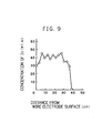
- Fig. 9 shows concentration of Zn in radial direction of this wire electrode. Region near surface of the wire electrode consists of ⁇ phase and the Zn concentration is approximately 30 wt. %. In the case where Zn concentration exceeds 40 wt. %, there appears ⁇ or ⁇ phase having a different crystal structure from that of ⁇ phase. At the depth of 5 to 30 ⁇ m from the surface of the wire electrode, Zn concentration ranges from 35 to 45 wt. % where ⁇ and ⁇ phases coexist and Cu-Zn intermetallic compound with relatively high Zn concentration is formed.
- ⁇ and ⁇ phases show the effect to blow out debris of the object material during electrical discharge machining and can enhance the machining speed, those are brittle in a sense of metallography and have a difficulty in cold wire drawing in wire electrode manufacturing.
- core material i.e. a core
- Cu-Zn intermetallic compound comprising ⁇ and ⁇ phases. Therefore, there are limitations in increasing Zn concentration of the Cu-Zn intermetallic layer and improving machining speed. Further, since ⁇ phase is surround by ⁇ phase, the effect of improvement in rigidity of the wire electrode which ⁇ phase intrinsically has cannot be exhibited adequately.
- the present invention is made to solve the above problems and an object thereof is to increase Zn concentration in the coating layer and to improve the machining speed.
- a further object of the present invention is to remove object material efficiently and improve the machining speed and accuracy of machining, by improving the rigidity of wire electrode and suppressing the vibration during machining.
- the present invention is characterized in that a wire electrode has three-layered structure of an electroconductive core (1), a coating layer (2) made of Cu-Zn intermetallic compounds existing as other than ⁇ phase, and an outer coating layer (3) made of Cu-Zn alloy existing as ⁇ phase, and that thickness of the coating layer (3) is 5 to 15 ⁇ m.
- the coating layer (2) is preferably Cu-Zn alloy in ⁇ phase.
- the core (1) is preferably made of Cu-Zr alloy.
- the core (1) might be made of Cu-Zn alloy.
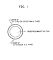
- Fig. 1 shows a cross section of the wire electrode.
- the wire electrode according to the present invention has a three-layered structure wherein a coating layer 2 of Cu-Zn intermetallic compound in other than ⁇ phase surrounds an electroconductive core 1, and a coating layer 3 of Cu-Zn alloy in ⁇ phase is formed outside the coating layer 2.
- the Cu-Zn intermetallic compound which constitutes the coating layer 2 is in other than ⁇ phase and the thickness thereof is increased to the utmost. Since the workability of wire drawing in wire electrode manufacturing becomes worse by increasing the thickness of the phase other than ⁇ phase, the thickness of coating layer 3 which is in ⁇ phase is increased as much as possible.
- Fig. 2 shows a photograph of cross section of the wire electrode of the present invention. There can be clearly seen that the coating layer 3 of Cu-Zn alloy in ⁇ phase and the coating layer 2 of Cu-Zn intermetallic compound in other than ⁇ phase is clearly separated from each other to form a three-layered structure including the core 1.
- the coating layer 2 of Cu-Zn intermetallic compound in other than ⁇ phase has higher Zn concentration compared with the coating layer 3 of Cu-Zn alloy in ⁇ phase.
- Zn concentration in a radial direction of cross section is shown for the wire electrode of the present invention.
- the coating layer 3 of Cu-Zn alloy in ⁇ phase exists and Zn concentration is around 35 wt. %.
- the coating layer 2 of Cu-Zn intermetallic layer in other than ⁇ phase exists and Zn concentration is around 45 wt. %.
- the discharge point of the wire electrode is eroded by 5 to 10 ⁇ m in a radial direction. Therefore, even if the thickness of the coating layer 3 of Cu-Zn intermetallic compound in ⁇ phase is set to 5 to 15 ⁇ m according to the present invention, the coating layer 2 of Cu-Zn intermetallic compound in other than ⁇ phase and with a high Zn concentration is exposed to the surface by one to three discharge(s) happened at the same point.
- Cu-Zn inter metallic compound in other than ⁇ phase especially ⁇ phase that firstly appears when increasing Zn concentration of ⁇ phase, has larger effects of evaporating and blowing off the object material through discharges than those of ⁇ phase.
- ⁇ phase that firstly appears when increasing Zn concentration of ⁇ phase
- machining speed by discharges can be enhanced.
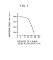
- Fig. 4 shows a relationship between the thickness of the coating layer 3 of Cu-Zn alloy in ⁇ phase and machining speed.
- the thickness of the coating layer 2 of intermetallic compound in other than ⁇ phase is constant to be 25 ⁇ m.
- machining speed is nearly constant when thickness of the coating layer 3 of Cu-Zn alloy in ⁇ phase is not more than 15 ⁇ m. That is, when thickness of the coating layer 3 of Cu-Zn alloy in ⁇ phase is not more than 15 ⁇ m, machining speed can be increased since the coating layer 2 of Cu-Zn intermetallic compound in other than ⁇ phase appears at the surface through one or two discharge(s).
- thickness of the coating layer 3 of Cu-Zn alloy in ⁇ phase is not more than 5 ⁇ m, wire drawing workability in manufacturing wire electrodes becomes extremely worse. Therefore, thickness of the coating layer 3 of Cu-Zn alloy in ⁇ phase is preferably larger than 5 ⁇ m and within 15 ⁇ m.
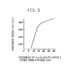
- Fig. 5 shows a relationship between the thickness of the coating layer 2 of Cu-Zn intermetallic compound in other than ⁇ phase and machining speed.
- the thickness of the coating layer 3 of Cu-Zn alloy in ⁇ phase is constant to be 15 ⁇ m.
- the thickness of the coating layer 2 of Cu-Zn intermetallic layer in other than ⁇ phase is set to 20 to 40 ⁇ m, the coating layer 2 is not exhausted during electric discharge machining process so that machining can be stable and the speed thereof can be remarkably increased.
- diameter of the wire electrode is 0.3mm in the above example, similar effect can be obtained for the case in which diameter of the wire electrode is 0.1 to 0.4mm.
- the reason therefore is that diameter of the core 1 is required so as not to break, with bearing tension which is applied for retaining the wire electrode, hence, minimum diameter of the wire electrode including the coating layers 2 and 3 is required to be approximately 0.1mm.
- maximum diameter is not limited, but considering the process of wire electrode production and industrial application for the electric discharge machine, approximately 0.4mm is practical. Meanwhile, diameter of the core 1 is about 0.22mm in the case where diameter of the wire electrode is 0.3mm.
- a wire electrode has a three-layered structure wherein a core 1 having a diameter of 0.22mm is surrounded by a coating layer 2 of Cu-Zn alloy in ⁇ phase having a thickness of 30 ⁇ m and further the periphery of the coating layer 2 is coated with a coating layer 3 of Cu-Zn alloy in ⁇ phase having a thickness of 10 ⁇ m.
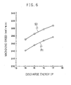
- machining speed of this wire electrode is shown in comparison with that of the conventional wire electrode.
- a conventional wire electrode there was used one wherein a core having a diameter of 0.22mm is surrounded by Cu-Zn intermetallic layer having a thickness of 20 ⁇ m and in which ⁇ phase is surrounded by ⁇ phase, and the periphery of the intermetallic layer is surrounded by Cu-Zn alloy in ⁇ phase having a thickness of not more than 5 ⁇ m.
- core material Cu-Zn alloy with 35 wt. % Zn concentration was used for both of the present embodiment and the conventional wire electrode.
- discharge energy IP is shown in abscissa while machining speed is shown in ordinate, and a curved line S1 denotes the wire electrode in the present embodiment while a curved line P1 denotes the conventional wire electrode.
- a curved line S1 denotes the wire electrode in the present embodiment
- a curved line P1 denotes the conventional wire electrode.
- a wire electrode is exposed to extremely high temperature during wire electrical discharge machining.
- Cu-Zr alloy which shows little degradation in electrical conductivity and in mechanical strength to suppress vibration of the wire electrode even at a high temperature is used for a core 1
- a coating layer 2 of Cu-Zn intermetallic compound in other than ⁇ phase is formed on the periphery of the core 1
- a coating layer 3 of Cu-Zn alloy in ⁇ phase is formed on the periphery of the coating layer 2 to form a wire electrode having a three-layered structure.
- machining speed of this wire electrode is shown in comparison with that of the conventional wire electrode.
- the conventional wire electrode there was used one wherein a core of Cu-Zn alloy having a diameter of 0.22mm is surrounded by Cu-Zn intermetallic layer having a thickness of 20 ⁇ m and in which ⁇ phase is surrounded by ⁇ phase, and the periphery of the intermetallic layer is surrounded by Cu-Zn alloy in ⁇ phase having a thickness of not more than 5 ⁇ m is used.
- discharge energy IP is shown in abscissa while machining speed is shown in ordinate, and a curved line S2 denotes the wire electrode of the present embodiment while a curved line P2 denotes the conventional wire.
- the wire electrode of the present embodiment in addition to an effect of blowing off the debris originated from discharges thanks to the coating layer 2 of Cu-Zn intermetallic compound in other than ⁇ phase, decreases an energy loss thanks to improvement in electrical conductivity, resulting in increase of energy contributing for discharges and increase in machining speed by 30 mm 2 /min at maximum compared with the conventional wire electrode, which is found to be very useful in industrial application.
- a wire electrode has a three-layered structure, wherein a coating layer 2 of Cu-Zn alloy in ⁇ phase is formed to surround a core 1 of Cu-Zr alloy and the periphery of the coating layer 2 is coated with a coating layer 3 of Cu-Zn alloy in ⁇ phase.
- machining speed of the wire electrode according to the present embodiment is shown with a curved line S3.
- ⁇ phase Cu-Zn intermetaric compound layer 2 to blow off the debris generated through discharges
- decrease in energy loss thanks to improvement in electrical conductivity results in increase of energy contributing for discharges so that machining speed is increased like in the case of Embodiment 3, thereby the wire electrode of the present embodiment is very useful in an industrial application.
- the thickness of the coating layer 3 of Cu-Zn alloy in ⁇ phase is set to 5 to 15 ⁇ m, the wire electrode of fine diameter is easily formed without generation of any cracks and breaks even if the thickness of the coating layer 2 of Cu-Zn metallic compound in other than ⁇ phase is increased, and also high machining speed can be obtained thanks to the existence of the coating layer 2 of Cu-Zn metallic compound in other than ⁇ phase with high Zn concentration.
- the wire electrode of fine diameter can be easily formed without generation of any cracks and breaks even if the thickness of the coating layer 2 of Cu-Zn alloy in ⁇ phase is increased. Further, high machining speed can be obtained thanks to the existence of the coating layer 2 of Cu-Zn alloy in ⁇ phase with high Zn concentration which has a large effect of blowing off the object material during discharges. Furthermore, since rigidity of the wire electrode is increased by the existence of ⁇ phase, vibration of the wire electrode during machining process is suppressed so that elimination of the object material is efficiently performed, and machining speed as well as accuracy in machining are enhanced.
- the wire electrode of fine diameter is easily formed without generation of any cracks and breaks even if the thickness of the coating layer 2 of Cu-Zn metallic compound in other than ⁇ phase is increased, and also high machining speed can be obtained thanks to the existence of the coating layer 2 of Cu-Zn metallic compound in other than ⁇ phase with high Zn concentration. Furthermore, by using Cu-Zr alloy for the core, electrical conductivity does not decrease even at a high temperature, which results in suppressing the discharge energy loss at the wire electrode and can increases the machining speed.
- the wire electrode of fine diameter can be easily formed without generation of any cracks and breaks even if the thickness of the coating layer 2 of Cu-Zn alloy in ⁇ phase is increased. Furthermore, high machining speed can be obtained thanks to the existence of the coating layer 2 of Cu-Zn alloy in ⁇ phase with high Zn concentration which has a large effect of blowing off the object material during discharges. Further, since rigidity of the wire electrode is increased by the existence of ⁇ phase, vibration of the wire electrode during machining process is suppressed so that elimination of the object material is efficiently performed, and machining speed as well as accuracy in machining are enhanced. Furthermore, by using Cu-Zr alloy for the core, electrical conductivity does not decrease even at a high temperature, which results in suppressing the discharge energy loss at the wire electrode and can increases the machining speed.
Landscapes
- Chemical & Material Sciences (AREA)
- Chemical Kinetics & Catalysis (AREA)
- Electrochemistry (AREA)
- Engineering & Computer Science (AREA)
- Mechanical Engineering (AREA)
- Electrical Discharge Machining, Electrochemical Machining, And Combined Machining (AREA)
Abstract
The present invention aims to increase concentration of Zn in
a coating layer to enhance machining speed. Moreover, the present
invention aims to perform removal of object material efficiently and
enhance machining speed as well as accuracy in machining by
increasing rigidity of the wire electrode to suppress vibration thereof
during machining process.
The present invention is characterized in that the wire
electrode for wire electrical discharge machine is constituted as a
three-layered structure of an electroconductive core (1), a coating layer
(2) of Cu-Zn intermetaric compound in other than α phase and a coating
layer (3) of Cu-Zn alloy in α phase on the exterior of the coating layer (2),
and that the thickness of the coating layer (3) is set to 5 to 15 µm.
Furthermore, the coating layer (2) is preferably Cu-Zn alloy in β phase.
Moreover, the core (1) is preferably made of Cu-Zr alloy.
Description
The present invention relates to a wire electrode to be used in
a discharge machining with a wire electrical discharge machine.
A wire electrical discharge machine is a device which
machines a workpiece by discharges between a wire electrode and the
workpiece.
In order to increase the machining speed, an example of a
wire electrode for a wire electrical discharge machine, wherein core
material (i.e. a core) is coated with a layer of Cu-Zn intermetallic
compound, is disclosed in HITACHI CABLE REVIEW No.18 (October
1999). A photograph of cross section of this wire electrode is shown in
Fig. 8. The figure is a magnification of region near surface of the wire
electrode, wherein the coating layer of Cu-Zn intermetallic compound
covering the core can be seen. In Fig. 8, β phase of the intermetallic
compound is seen in a string-like pattern and is surrounded by α phase.
Moreover, the outermost region of the wire electrode consists of only α
phase.
β phase which has higher Zn concentration than α phase has
an advantage to increase machining speed, because β phase easily
evaporates through discharges to blow out object material. On the
other hand, β phase is brittle in a sense of metallography and has a
disadvantage that there easily occur cracks during a cold wire drawing
process in manufacturing a wire electrode. Since α phase with superior
workability surrounds β phase with difficult workability, a wire electrode
as shown in Fig. 8 can be easily formed to be a fine wire without any
cracks or breaks during a cold wire drawing process.
Further, a similar wire electrode for a wire electrical
discharge machine is disclosed in Japanese Unexamined Patent
Publication No.300136/1997. Fig. 9 shows concentration of Zn in
radial direction of this wire electrode. Region near surface of the wire
electrode consists of α phase and the Zn concentration is approximately
30 wt. %. In the case where Zn concentration exceeds 40 wt. %, there
appears β or γ phase having a different crystal structure from that of α
phase. At the depth of 5 to 30 µm from the surface of the wire electrode,
Zn concentration ranges from 35 to 45 wt. % where α and β phases
coexist and Cu-Zn intermetallic compound with relatively high Zn
concentration is formed.
As already described, although β and γ phases show the
effect to blow out debris of the object material during electrical discharge
machining and can enhance the machining speed, those are brittle in a
sense of metallography and have a difficulty in cold wire drawing in wire
electrode manufacturing.
Thus, in the conventional wire electrode for a wire electrical
discharge machine, core material (i.e. a core) is surrounded by a layer of
Cu-Zn intermetallic compound comprising β and α phases. Therefore,
there are limitations in increasing Zn concentration of the Cu-Zn
intermetallic layer and improving machining speed. Further, since β
phase is surround by α phase, the effect of improvement in rigidity of the
wire electrode which β phase intrinsically has cannot be exhibited
adequately.
The present invention is made to solve the above problems
and an object thereof is to increase Zn concentration in the coating layer
and to improve the machining speed. A further object of the present
invention is to remove object material efficiently and improve the
machining speed and accuracy of machining, by improving the rigidity of
wire electrode and suppressing the vibration during machining.
The present invention is characterized in that a wire electrode
has three-layered structure of an electroconductive core (1), a coating
layer (2) made of Cu-Zn intermetallic compounds existing as other than
α phase, and an outer coating layer (3) made of Cu-Zn alloy existing as α
phase, and that thickness of the coating layer (3) is 5 to 15 µm.
Further, the coating layer (2) is preferably Cu-Zn alloy in β
phase.
Moreover, the core (1) is preferably made of Cu-Zr alloy.
Furthermore, the core (1) might be made of Cu-Zn alloy.
A wire electrode for a wire electrical discharge machine
according to an embodiment of the present invention is described with
referring to Fig. 1. Fig. 1 shows a cross section of the wire electrode.
The wire electrode according to the present invention has a three-layered
structure wherein a coating layer 2 of Cu-Zn intermetallic compound in
other than α phase surrounds an electroconductive core 1, and a coating
layer 3 of Cu-Zn alloy in α phase is formed outside the coating layer 2.
The Cu-Zn intermetallic compound which constitutes the coating layer 2
is in other than α phase and the thickness thereof is increased to the
utmost. Since the workability of wire drawing in wire electrode
manufacturing becomes worse by increasing the thickness of the phase
other than α phase, the thickness of coating layer 3 which is in α phase
is increased as much as possible.
Fig. 2 shows a photograph of cross section of the wire
electrode of the present invention. There can be clearly seen that the
coating layer 3 of Cu-Zn alloy in α phase and the coating layer 2 of Cu-Zn
intermetallic compound in other than α phase is clearly separated
from each other to form a three-layered structure including the core 1.
The coating layer 2 of Cu-Zn intermetallic compound in other
than α phase has higher Zn concentration compared with the coating
layer 3 of Cu-Zn alloy in α phase. In Fig. 3, Zn concentration in a radial
direction of cross section is shown for the wire electrode of the present
invention. In the region where the distance from the wire electrode
surface is 0 to 15 µm, the coating layer 3 of Cu-Zn alloy in α phase exists
and Zn concentration is around 35 wt. %. In the region where the
distance from the wire electrode surface is 15 to 40 µm, the coating layer
2 of Cu-Zn intermetallic layer in other than α phase exists and Zn
concentration is around 45 wt. %.
In a machining process with a wire electrical discharge
machine, once a single discharge occurs between the workpiece and the
wire electrode, the discharge point of the wire electrode is eroded by 5 to
10 µm in a radial direction. Therefore, even if the thickness of the
coating layer 3 of Cu-Zn intermetallic compound in α phase is set to 5 to
15 µm according to the present invention, the coating layer 2 of Cu-Zn
intermetallic compound in other than α phase and with a high Zn
concentration is exposed to the surface by one to three discharge(s)
happened at the same point. Cu-Zn inter metallic compound in other
than α phase, especially β phase that firstly appears when increasing Zn
concentration of α phase, has larger effects of evaporating and blowing
off the object material through discharges than those of α phase. Thus,
because of appearance of the coating layer 2 of Cu-Zn intermetallic
compound in other than α phase at the surface, machining speed by
discharges can be enhanced.
Fig. 4 shows a relationship between the thickness of the
coating layer 3 of Cu-Zn alloy in α phase and machining speed. The
thickness of the coating layer 2 of intermetallic compound in other than
α phase is constant to be 25 µm. As is apparent from Fig. 4, machining
speed is nearly constant when thickness of the coating layer 3 of Cu-Zn
alloy in α phase is not more than 15 µm. That is, when thickness of the
coating layer 3 of Cu-Zn alloy in α phase is not more than 15 µm,
machining speed can be increased since the coating layer 2 of Cu-Zn
intermetallic compound in other than α phase appears at the surface
through one or two discharge(s).
When thickness of the coating layer 3 of Cu-Zn alloy in α
phase is not more than 5 µm, wire drawing workability in manufacturing
wire electrodes becomes extremely worse. Therefore, thickness of the
coating layer 3 of Cu-Zn alloy in α phase is preferably larger than 5 µm
and within 15 µm.
Fig. 5 shows a relationship between the thickness of the
coating layer 2 of Cu-Zn intermetallic compound in other than α phase
and machining speed. The thickness of the coating layer 3 of Cu-Zn
alloy in α phase is constant to be 15 µm. The larger the thickness of the
coating layer 2 of Cu-Zn intermetallic compound in other than α phase
having a high Zn concentration is, the more machining speed is
improved.
For a wire electrode having a diameter of 0.3 mm, if the
thickness of the coating layer 2 of Cu-Zn intermetallic layer in other than
α phase is set to 20 to 40µm, the coating layer 2 is not exhausted during
electric discharge machining process so that machining can be stable
and the speed thereof can be remarkably increased.
It is because there occurs difficulty in workability during wire
electrode manufacturing that whole cross section except the outermost
coating layer 3 cannot be made of Cu-Zn intermetallic compounds in
other than α phase.
Although diameter of the wire electrode is 0.3mm in the
above example, similar effect can be obtained for the case in which
diameter of the wire electrode is 0.1 to 0.4mm. The reason therefore is
that diameter of the core 1 is required so as not to break, with bearing
tension which is applied for retaining the wire electrode, hence,
minimum diameter of the wire electrode including the coating layers 2
and 3 is required to be approximately 0.1mm. Further, maximum
diameter is not limited, but considering the process of wire electrode
production and industrial application for the electric discharge machine,
approximately 0.4mm is practical. Meanwhile, diameter of the core 1 is
about 0.22mm in the case where diameter of the wire electrode is
0.3mm.
In the present embodiment, a wire electrode has a three-layered
structure wherein a core 1 having a diameter of 0.22mm is
surrounded by a coating layer 2 of Cu-Zn alloy in β phase having a
thickness of 30 µm and further the periphery of the coating layer 2 is
coated with a coating layer 3 of Cu-Zn alloy in α phase having a
thickness of 10µm.
In Fig. 6, machining speed of this wire electrode is shown in
comparison with that of the conventional wire electrode. As a
conventional wire electrode, there was used one wherein a core having a
diameter of 0.22mm is surrounded by Cu-Zn intermetallic layer having a
thickness of 20 µm and in which β phase is surrounded by α phase, and
the periphery of the intermetallic layer is surrounded by Cu-Zn alloy in α
phase having a thickness of not more than 5 µm. As core material,
Cu-Zn alloy with 35 wt. % Zn concentration was used for both of the
present embodiment and the conventional wire electrode.
In Fig. 6, discharge energy IP is shown in abscissa while
machining speed is shown in ordinate, and a curved line S1 denotes the
wire electrode in the present embodiment while a curved line P1 denotes
the conventional wire electrode. For the wire electrode of the present
embodiment, an increase in machining speed by 30 mm2/min is seen at
maximum compared with the conventional wire, which is found to be
very useful in industrial application.
A wire electrode is exposed to extremely high temperature
during wire electrical discharge machining. In the present embodiment,
therefore, Cu-Zr alloy which shows little degradation in electrical
conductivity and in mechanical strength to suppress vibration of the
wire electrode even at a high temperature is used for a core 1, a coating
layer 2 of Cu-Zn intermetallic compound in other than α phase is formed
on the periphery of the core 1, and further a coating layer 3 of Cu-Zn
alloy in α phase is formed on the periphery of the coating layer 2 to form
a wire electrode having a three-layered structure.
In Fig. 7, machining speed of this wire electrode is shown in
comparison with that of the conventional wire electrode. As the
conventional wire electrode, there was used one wherein a core of Cu-Zn
alloy having a diameter of 0.22mm is surrounded by Cu-Zn intermetallic
layer having a thickness of 20 µm and in which β phase is surrounded
by α phase, and the periphery of the intermetallic layer is surrounded by
Cu-Zn alloy in α phase having a thickness of not more than 5 µm is
used.
In Fig. 7, discharge energy IP is shown in abscissa while
machining speed is shown in ordinate, and a curved line S2 denotes the
wire electrode of the present embodiment while a curved line P2 denotes
the conventional wire. The wire electrode of the present embodiment,
in addition to an effect of blowing off the debris originated from
discharges thanks to the coating layer 2 of Cu-Zn intermetallic
compound in other than α phase, decreases an energy loss thanks to
improvement in electrical conductivity, resulting in increase of energy
contributing for discharges and increase in machining speed by 30
mm2/min at maximum compared with the conventional wire electrode,
which is found to be very useful in industrial application.
Further, similar effect of increase in machining speed thanks
to the coating layers 2 and 3 can be obtained when the core 1 of Cu-Zr
alloy is substituted by inexpensive and easily available Cu-Zn alloy
which has higher tensile strength so as to suppress vibration of the wire
electrode.
In the present embodiment, a wire electrode has a three-layered
structure, wherein a coating layer 2 of Cu-Zn alloy in β phase is
formed to surround a core 1 of Cu-Zr alloy and the periphery of the
coating layer 2 is coated with a coating layer 3 of Cu-Zn alloy in α phase.
In Fig. 7, machining speed of the wire electrode according to
the present embodiment is shown with a curved line S3. In addition to
an effect of β phase Cu-Zn intermetaric compound layer 2 to blow off the
debris generated through discharges, decrease in energy loss thanks to
improvement in electrical conductivity results in increase of energy
contributing for discharges so that machining speed is increased like in
the case of Embodiment 3, thereby the wire electrode of the present
embodiment is very useful in an industrial application.
Further, similar effect of increase in machining speed thanks
to the coating layers 2 and 3 can be obtained when the core 1 of Cu-Zr
alloy is substituted by inexpensive and easily available Cu-Zn alloy
which has higher tensile strength so as to suppress vibration of the wire
electrode.
According to Embodiment 1 of the present invention, since
the thickness of the coating layer 3 of Cu-Zn alloy in α phase is set to 5 to
15 µm, the wire electrode of fine diameter is easily formed without
generation of any cracks and breaks even if the thickness of the coating
layer 2 of Cu-Zn metallic compound in other than α phase is increased,
and also high machining speed can be obtained thanks to the existence
of the coating layer 2 of Cu-Zn metallic compound in other than α phase
with high Zn concentration.
According to Embodiment 2 of the present invention, since
the thickness of the coating layer 3 of Cu-Zn alloy in α phase is set to 5 to
15 pm, the wire electrode of fine diameter can be easily formed without
generation of any cracks and breaks even if the thickness of the coating
layer 2 of Cu-Zn alloy in β phase is increased. Further, high machining
speed can be obtained thanks to the existence of the coating layer 2 of
Cu-Zn alloy in β phase with high Zn concentration which has a large
effect of blowing off the object material during discharges. Furthermore,
since rigidity of the wire electrode is increased by the existence of β
phase, vibration of the wire electrode during machining process is
suppressed so that elimination of the object material is efficiently
performed, and machining speed as well as accuracy in machining are
enhanced.
According to Embodiment 3 of the present invention, since
the thickness of the coating layer 3 of Cu-Zn alloy in α phase is set to 5 to
15 pm, the wire electrode of fine diameter is easily formed without
generation of any cracks and breaks even if the thickness of the coating
layer 2 of Cu-Zn metallic compound in other than α phase is increased,
and also high machining speed can be obtained thanks to the existence
of the coating layer 2 of Cu-Zn metallic compound in other than α phase
with high Zn concentration. Furthermore, by using Cu-Zr alloy for the
core, electrical conductivity does not decrease even at a high
temperature, which results in suppressing the discharge energy loss at
the wire electrode and can increases the machining speed.
Meanwhile, by using Cu-Zn alloy with a high tensile strength
for the core 1, vibration of the wire electrode is suppressed and higher
machining speed can be achieved.
According to Embodiment 4 of the present invention, since
the thickness of the coating layer 3 of Cu-Zn alloy in α phase is set to 5 to
15 µm, the wire electrode of fine diameter can be easily formed without
generation of any cracks and breaks even if the thickness of the coating
layer 2 of Cu-Zn alloy in β phase is increased. Furthermore, high
machining speed can be obtained thanks to the existence of the coating
layer 2 of Cu-Zn alloy in β phase with high Zn concentration which has a
large effect of blowing off the object material during discharges.
Further, since rigidity of the wire electrode is increased by the existence
of β phase, vibration of the wire electrode during machining process is
suppressed so that elimination of the object material is efficiently
performed, and machining speed as well as accuracy in machining are
enhanced. Furthermore, by using Cu-Zr alloy for the core, electrical
conductivity does not decrease even at a high temperature, which
results in suppressing the discharge energy loss at the wire electrode
and can increases the machining speed.
Meanwhile, by using Cu-Zn alloy with a high tensile strength
for the core 1, vibration of the wire electrode is suppressed and higher
machining speed can be achieved.
Claims (6)
- A wire electrode for wire electrical discharge machine characterized in that the wire electrode has a three-layered structure comprising an electroconductive core (1), a coating layer (2) of Cu-Zn intermetalic compound in other than α phase surrounding the core (1), and a coating layer (3) of Cu-Zn alloy in α phase on the exterior of the coating layer (2), and that the thickness of the coating layer (3) is 5 to 15 µm.
- The wire electrode for wire electrical discharge machine according to Claim 1, characterized in that the coating layer (2) comprises Cu-Zn alloy in β phase.
- The wire electrode for wire electrical discharge machine according to Claim 1, characterized in that the core (1) comprises Cu-Zr alloy.
- The wire electrode for wire electrical discharge machine according to Claim 2, characterized in that the core (1) comprises Cu-Zr alloy.
- The wire electrode for wire electrical discharge machine according to Claim 1, characterized in that the core (1) comprises Cu-Zn alloy.
- The wire electrode for wire electrical discharge machine according to Claim 2, characterized in that the core (1) comprises Cu-Zn alloy.
Applications Claiming Priority (1)
| Application Number | Priority Date | Filing Date | Title |
|---|---|---|---|
| PCT/JP2000/006632 WO2002026433A1 (en) | 2000-09-27 | 2000-09-27 | Electrode wire for wire electrical discharge machine |
Publications (2)
| Publication Number | Publication Date |
|---|---|
| EP1400299A1 true EP1400299A1 (en) | 2004-03-24 |
| EP1400299A4 EP1400299A4 (en) | 2005-12-07 |
Family
ID=11736524
Family Applications (1)
| Application Number | Title | Priority Date | Filing Date |
|---|---|---|---|
| EP00962856A Withdrawn EP1400299A4 (en) | 2000-09-27 | 2000-09-27 | WIRE-ELECTRODE FOR EINCELAGE MACHINING ASSEMBLY |
Country Status (3)
| Country | Link |
|---|---|
| EP (1) | EP1400299A4 (en) |
| JP (1) | JP3875636B2 (en) |
| WO (1) | WO2002026433A1 (en) |
Families Citing this family (1)
| Publication number | Priority date | Publication date | Assignee | Title |
|---|---|---|---|---|
| JP7852757B2 (en) * | 2024-07-23 | 2026-04-28 | 株式会社プロテリアル | Wire EDM electrode wire and method for manufacturing wire EDM electrode wire |
Family Cites Families (6)
| Publication number | Priority date | Publication date | Assignee | Title |
|---|---|---|---|---|
| CH633739A5 (en) * | 1980-03-25 | 1982-12-31 | Charmilles Sa Ateliers | Electrode in the form of a wire for cutting a metal workpiece by electrical discharge (spark erosion) |
| ATE89502T1 (en) * | 1989-02-01 | 1993-06-15 | Thermo Compact Sa | WIRE-SHAPED ELECTRODE WITH METALLIC COATING FOR SPARK EDM AND PROCESS FOR ITS MANUFACTURE. |
| JPH06190635A (en) * | 1992-12-25 | 1994-07-12 | Fujikura Ltd | Method for manufacturing electrode wire for wire electric discharge machining |
| CH690439A5 (en) * | 1995-12-11 | 2000-09-15 | Charmilles Technologies | A method of manufacturing son with a brass surface, for the purposes of the EDM wire. |
| DE69612732T2 (en) * | 1996-04-02 | 2002-04-18 | Swil Ltd., Kalkutta/Calcutta | Method for producing a wire electrode for spark erosion |
| JP3809740B2 (en) * | 1999-03-03 | 2006-08-16 | 日立電線株式会社 | Electrode wire for electric discharge machining |
-
2000
- 2000-09-27 JP JP2002530252A patent/JP3875636B2/en not_active Expired - Fee Related
- 2000-09-27 EP EP00962856A patent/EP1400299A4/en not_active Withdrawn
- 2000-09-27 WO PCT/JP2000/006632 patent/WO2002026433A1/en not_active Ceased
Also Published As
| Publication number | Publication date |
|---|---|
| JPWO2002026433A1 (en) | 2004-02-05 |
| WO2002026433A1 (en) | 2002-04-04 |
| EP1400299A4 (en) | 2005-12-07 |
| JP3875636B2 (en) | 2007-01-31 |
Similar Documents
| Publication | Publication Date | Title |
|---|---|---|
| JP3718617B2 (en) | Porous electrode wire for electrical discharge machining | |
| KR100868008B1 (en) | Wire electrode for spark erosion cutting | |
| JPWO1999006183A1 (en) | Manufacturing method of porous electrode wire for electric discharge machining and its structure | |
| KR101486028B1 (en) | Electrode wire for electrical discharge machining | |
| US5599633A (en) | Wire electrode for electro-discharge machining | |
| EP1400299A1 (en) | Electrode wire for wire electrical discharge machine | |
| JP3405069B2 (en) | Electrode wire for electric discharge machining | |
| JP3087552B2 (en) | Electrode wire for electric discharge machining | |
| EP1080815A2 (en) | Wire electrode for electric-discharge machining | |
| KR20020034537A (en) | Method for manufacturing plasma cutting electrode | |
| JP2002137123A (en) | Electrode wire for wire electric discharge machining | |
| JP2003039246A (en) | Electrode wire for wire electric discharge machining | |
| JPS63169222A (en) | Electrode wire for electrical discharge machining | |
| JP2001030008A (en) | Manufacture of copper or copper alloy-iron combined wire | |
| JPH05295472A (en) | Electrode wire for wire electrical discharge machining | |
| JPS6219326A (en) | Electrode wire for wire-cut electric discharge machining | |
| KR20260039618A (en) | Aluminum magnesium alloy wafer ring frame | |
| JP4323704B2 (en) | Electrode wire for wire electrical discharge machining | |
| JP2008062325A (en) | Electrode wire for wire electric discharge machining | |
| JP2006281337A (en) | Electrode wire for wire electric discharge machining | |
| JP2010123347A (en) | Vacuum valve and manufacturing method thereof | |
| JPS62208827A (en) | Electrode wire rod for wire electric discharge machining | |
| JPS597528A (en) | Wire electrode for electrical discharge machining | |
| JPS59110516A (en) | Wire-cut electrode wire for electrical discharge machining and its manufacturing method | |
| JPH11347847A (en) | Electrode wire for wire electric discharge machining |
Legal Events
| Date | Code | Title | Description |
|---|---|---|---|
| PUAI | Public reference made under article 153(3) epc to a published international application that has entered the european phase |
Free format text: ORIGINAL CODE: 0009012 |
|
| 17P | Request for examination filed |
Effective date: 20020624 |
|
| AK | Designated contracting states |
Kind code of ref document: A1 Designated state(s): DE |
|
| A4 | Supplementary search report drawn up and despatched |
Effective date: 20051020 |
|
| STAA | Information on the status of an ep patent application or granted ep patent |
Free format text: STATUS: THE APPLICATION HAS BEEN WITHDRAWN |
|
| 18W | Application withdrawn |
Effective date: 20060102 |