EP1399933B1 - Magnetic anchoring module with a system for enabling/disabling and adjusting the magnetic anchoring force - Google Patents
Magnetic anchoring module with a system for enabling/disabling and adjusting the magnetic anchoring force Download PDFInfo
- Publication number
- EP1399933B1 EP1399933B1 EP02758263A EP02758263A EP1399933B1 EP 1399933 B1 EP1399933 B1 EP 1399933B1 EP 02758263 A EP02758263 A EP 02758263A EP 02758263 A EP02758263 A EP 02758263A EP 1399933 B1 EP1399933 B1 EP 1399933B1
- Authority
- EP
- European Patent Office
- Prior art keywords
- magnetic
- multipolar
- statoric
- stator
- head
- Prior art date
- Legal status (The legal status is an assumption and is not a legal conclusion. Google has not performed a legal analysis and makes no representation as to the accuracy of the status listed.)
- Expired - Lifetime
Links
- 230000005291 magnetic effect Effects 0.000 title claims abstract description 312
- 238000004873 anchoring Methods 0.000 title claims abstract description 41
- 230000005294 ferromagnetic effect Effects 0.000 claims abstract description 80
- 230000004907 flux Effects 0.000 claims description 21
- 230000004323 axial length Effects 0.000 claims 1
- 230000010287 polarization Effects 0.000 claims 1
- 230000008878 coupling Effects 0.000 description 3
- 238000010168 coupling process Methods 0.000 description 3
- 238000005859 coupling reaction Methods 0.000 description 3
- 239000011159 matrix material Substances 0.000 description 2
- 239000000203 mixture Substances 0.000 description 2
- OKTJSMMVPCPJKN-UHFFFAOYSA-N Carbon Chemical compound [C] OKTJSMMVPCPJKN-UHFFFAOYSA-N 0.000 description 1
- 229910000831 Steel Inorganic materials 0.000 description 1
- XAGFODPZIPBFFR-UHFFFAOYSA-N aluminium Chemical compound [Al] XAGFODPZIPBFFR-UHFFFAOYSA-N 0.000 description 1
- 229910052782 aluminium Inorganic materials 0.000 description 1
- 239000004411 aluminium Substances 0.000 description 1
- 230000005540 biological transmission Effects 0.000 description 1
- 229910052799 carbon Inorganic materials 0.000 description 1
- 238000010276 construction Methods 0.000 description 1
- 238000006073 displacement reaction Methods 0.000 description 1
- 230000000694 effects Effects 0.000 description 1
- 239000003302 ferromagnetic material Substances 0.000 description 1
- 239000000835 fiber Substances 0.000 description 1
- 230000001939 inductive effect Effects 0.000 description 1
- 239000000463 material Substances 0.000 description 1
- 230000001105 regulatory effect Effects 0.000 description 1
- 238000004513 sizing Methods 0.000 description 1
- 230000003068 static effect Effects 0.000 description 1
- 239000010959 steel Substances 0.000 description 1
Images


Classifications
-
- H—ELECTRICITY
- H01—ELECTRIC ELEMENTS
- H01F—MAGNETS; INDUCTANCES; TRANSFORMERS; SELECTION OF MATERIALS FOR THEIR MAGNETIC PROPERTIES
- H01F7/00—Magnets
- H01F7/02—Permanent magnets [PM]
- H01F7/0231—Magnetic circuits with PM for power or force generation
- H01F7/0252—PM holding devices
Definitions
- the present invention refers to a magnetic module equipped with a system for enabling the magnetic force for anchoring a further magnetic, or ferromagnetic module to a ferromagnetic surface, for use in the case of the magnetic module developing a magnetic force of attraction comparable with or superior to the limit of human force.
- the European patent application No. EP 1 080 476 which is the property of the present applicant, describes an assembly resulting from a combination of magnetic modules with other magnetic and/or ferromagnetic modules.
- the magnetic modules referred to in said application include at least one active magnetic element, i.e. an element that has two polar surfaces of opposite sign, and at least one ferromagnetic element.
- One of the fundamental characteristics of the assembly described in the European patent application No. EP 1 080 476 consists in the fact that the magnetic flux generated by the active magnetic elements involved in the anchorage between modules is at least partially short-circuited through the modules' ferromagnetic elements, and in the fact that the differences in magnetic potential produced by the active magnetic elements involved in the anchorage between modules are added together in series.
- Such an anchoring system enables a high ratio to be achieved between the anchoring force between the modules in the assembly and the weight of the assembly as a whole, thus enabling the construction of even highly-complex self-supporting lattice structures, e.g. scaffolding for theatre stage scenery, or advertising panels.
- the aim of the present invention is thus to produce a magnetic module equipped with a system for enabling/disabling the magnetic force for anchoring the magnetic module to a ferromagnetic surface of another magnetic, or ferromagnetic module.
- This aim is achieved by equipping a magnetic module with a system for enabling/disabling the magnetic anchoring force of the magnetic module by means of a pole inversion system of mechanical/manual or mechanical/electrical type consistent with independent claim 1, or of electromagnetic type consistent with independent claim 8.
- the magnetic module with mechanical-manual or mechanicalelectrical pole inversion system is characterised in that it has at least one axially extending head equipped with a system for enabling a magnetic force for anchoring said magnetic module to a ferromagnetic surface, said at least one head comprising:
- Said magnetic stator includes a number of statoric permanent magnets placed around the axis of the magnetic stator and a number of ferromagnetic sectors each interposed between a corresponding couple of statoric permanent magnets of said number of statoric permanent magnets; said statoric permanent magnets having polarisation axis oriented substantially parallel to the multipolar statoric surface, said statoric permanent magnets of each couple of statoric permanent magnets facing each to the other with a magnetic polarity of identical sign; said anchoring multipolar statoric surface being formed by the composition of a surface of each of said ferromagnetic sectors.
- Said magnetic rotor includes: a number of rotoric permanent magnets placed around the axis of the magnetic rotor, said rotoric permanent magnets having polarisation axis oriented substantially orthogonal to the multipolar statoric surface, each of said rotoric permanent magnets having a magnetic polarisation opposite to that of the adjacent rotoric permanent magnet; and a ferromagnetic yoke applied for connecting the magnetic poles opposite to the magnetic stator of all said rotoric permanent magnets.
- the magnetic module with electromagnetic pole inversion system is characterised in that it has at least one axially extending head equipped with a system for enabling a magnetic force for anchoring said magnetic module to a ferromagnetic surface, said at least one head comprising:
- Said first magnetic stator includes a number of first statoric permanent magnets placed around the axis of the first magnetic stator and a number of ferromagnetic sectors each interposed between a corresponding couple of first statoric permanent magnets of said number of first statoric permanent magnets; said first statoric permanent magnets having polarisation axis oriented substantially parallel to the multipolar first statoric surface, said first statoric permanent magnets of each couple of first statoric permanent magnets facing each to the other with a magnetic polarity of identical sign; said first anchoring multipolar statoric surface being formed by the composition of a surface of each of said ferromagnetic sectors.
- Said second magnetic stator includes: a number of electromagnets placed around the axis of the second magnetic stator, said electromagnets having polarisation axis oriented substantially orthogonal to the multipolar statoric surface, each of said electromagnets having a magnetic polarisation opposite to that of the adjacent electromagnet; and a ferromagnetic yoke applied for connecting the magnetic poles opposite to the first magnetic stator of all said electromagnets.
- the invention also describes an assembly of said magnetic modules, combined with each other, and possibly also with ferromagnetic modules, characterised in that the ferromagnetic anchoring surface in the assembly is provided by a ferromagnetic element integrated in the magnetic modules, or belonging to any separate ferromagnetic modules that may be included in the assembly, or by the anchoring multipolar magnetic statoric surface of the head(s) of the other magnetic modules.
- the head of one magnetic module can be anchored directly to the head of another magnetic module, or the head of one or more magnetic modules can be anchored to a ferromagnetic element of another magnetic module, or the head of one or more magnetic modules can be anchored to a ferromagnetic module.
- a magnetic circuit generated by the enabled head of one or more concurrent magnetic modules on the ferromagnetic anchoring surface; in said magnetic circuit the magnetic flux generated on the ferromagnetic anchoring surface by said enabled head of said one or more concurrent magnetic modules is totally or at least partially short-circuited through said head of said one or more concurrent magnetic modules on the ferromagnetic anchoring surface, and through ferromagnetic anchoring surface provided by said ferromagnetic element; in said magnetic circuit, moreover, the differences in magnetic potential produced by said enabled head of said one or more concurrent magnetic modules on the ferromagnetic anchoring surface combine, being added together in series.
- the ferromagnetic modules can also be composed of a ferromagnetic element coated with a non-magnetic matrix, e.g. a material with a high static friction coefficient.
- the system for enabling/disabling the anchorage of the magnetic module in the present invention is quick and easy, and it allows for a high ratio of the anchoring force between the modules in the assembly to the global weight of the assembly to be maintained in the enabled phase.
- the system for enabling/disabling the anchorage of the magnetic module allows for the magnetic flux generated by the magnetic elements in the head to be completely short circuited inside the head of the magnetic module.
- the present invention offers a system for enabling/disabling the one or more heads of a magnetic module that is capable of regulating the anchoring force and is also equipped with a device for preventing its accidental disabling.
- each head can operate independently of the other.
- Figures 1 to 4 refer to a magnetic module 1 equipped with a head 3 that can be enabled to achieve a magnetic anchorage to the ferromagnetic surface of a spherical ferromagnetic module 5.
- the head 3 of the module 1 extends in an axial direction, indicated by the line of dots and dashes A-A in figure 2 , and comprises an axially hollow cylindrical ferrule 7 equipped with a tapered tip 8, a magnetic stator 9 and a magnetic rotor 11 lying opposite, coaxially and internally with respect to the ferrule 7.
- the magnetic stator 9 occupies an axial position with respect to the ferrule 7, corresponding to the tip 8 of the ferrule 7, while the magnetic rotor 11 occupies a more internal axial position.
- the magnetic stator 9 is composed of a main ferromagnetic element or body 13 divided radially into six identical sectors 15 by six radial grooves 17 lying at equal angles in planes passing through the axis of the head 3.
- An active magnetic element i.e. a permanent magnet 19 is attached inside each groove 17 in the main ferromagnetic body 13 of the magnetic stator 9.
- the permanent magnets 19 are identical and are arranged with their magnetic polarisation axis substantially parallel to the head surface 21 of the magnetic stator, while each pair of adjacent permanent magnets 19 presents a magnetic polarity of the same sign towards the ferromagnetic sector 15 it defines.
- the six sectors 15 of the main ferromagnetic body 13 of the magnetic stator 9 form an anchoring multipolar statoric surface 21 magnetically induced by the active magnetic elements 19 with an alternately positive and negative magnetic polarity.
- the main ferromagnetic body 13 of the magnetic stator 9 may be in a single piece, as described above, or it may also be divided into completely separate sectors arranged around an angle of 360° and laterally spaced from each other in such a way as to define seats for housing the permanent magnets of the magnetic stator 9.
- the multipolar head surface 21 of the main ferromagnetic body 13 of the magnetic stator 9 is aligned at the tip 8 of the ferrule 7 and composed of six polar areas with a 60° angle of aperture and a specular multipolar base surface 23.
- the magnetic stator 9 can be fixed to the ferrule 7 by means of a mechanical keying between projections 25 on the ferrule 7 and corresponding recesses 27 in the magnetic stator body 9.
- the magnetic rotor 11 of the head 3 comprises six identical active magnetic elements, i.e. six permanent magnets 29, and a ferromagnetic element or yoke 31 for connecting and supporting the permanent magnets 29 positioned, with respect to the permanent magnets 29, on the side opposite the magnetic stator 9.
- the six permanent magnets 29 of the magnetic rotor 11 have a polarisation axis orthogonal to the statoric multipolar surface 21.
- the six permanent magnets 29 of the magnetic rotor 11 are arranged at equal angles around the axis of the head 3 and with an alternating polarity so as to generate a multipolar rotoric surface 33 specular to the anchoring multipolar statoric surface 21.
- the sizing of the magnetic and ferromagnetic components of the magnetic stator 9 and of the magnetic rotor 11 must be such that, when the head 3 is disabled, when every pole of the multipolar statoric surface 21 is magnetically in series with a corresponding pole of the multipolar rotoric surface 33, the magnetic rotor 11 can completely absorb the magnetic flux generated by the magnetic stator 9, short circuiting said flux completely through the ferromagnetic yoke 31 so as to leave the multipolar statoric surface 21 of the magnetic stator 9 disabled for the purposes of the anchorage of the magnetic module 1 to the ferromagnetic surface of module 5.
- the ferromagnetic module 5 is hollow and its thickness must be kept to a minimum in order to increase the ratio of the magnetic anchoring force between the two modules to the weight of the two modules, nonetheless taking into account that the thickness of the ferromagnetic module 5 cannot drop below a certain value in order to guarantee the total short circuiting of the magnetic flux generated by the head 3.
- a complete short circuit of the magnetic flux can be maintained by compensating for any reduction in the thickness of the ferromagnetic module 5 with an increase in the number of pairs of poles in the magnetic stator 9.
- the part of the magnetic rotor corresponding to the permanent magnets 29 and the yoke 31 that connects them can be replaced by a body having the same structure as the magnetic stator 9, i.e. a main ferromagnetic body containing a set of active magnetic elements placed exactly as in the magnetic stator 9.
- the multipolar rotoric surface 33 is induced by the active magnetic elements of the magnetic rotor.
- the magnetic rotor 11 comprises a bell 35 for guiding the rotation of the magnetic rotor 11, coaxial and internal with respect to the ferrule 7 and solidly extending to the yoke 31 for supporting the permanent magnets 29 of the magnetic rotor 11 from the yoke 31 side opposite the permanent magnets 29.
- the bell 35 for guiding the magnetic rotor 11 is itself guided by the inside wall of the ferrule 7.
- the multipolar rotoric surface 33 and the base surface 23 of the magnetic stator 9 are each equipped with high-strength steel friction plates designed to facilitate the relative rotation between the magnetic stator 9 and the magnetic rotor 11, while offering a minimum resistance to the passage of the magnetic flux from one side to the other.
- the head 3 of the magnetic module 1 comprises a cylindrical ring 37 keyed coaxially and externally to the ferrule 7 so that it can tum and slide with respect to the axis of the ferrule 7 to mechanically/manually drive the rotation of the magnetic rotor 11.
- the ring 37 diametrically supports a drive rod 39 fitted in a pair of diametrically-aligned slots 41 cut in the edge 43 at the end of the bell 35 situated axially opposite the magnetic stator 9.
- the slots 41 are axially elongated so as to keep the drive rod 39 engaged but free to slide in the axial direction of the ferrule 7.
- the drive rod 39 is placed across two slits 45 cut along two diametrically-opposite stretches of the circumference of the ferrule 7.
- the slits 45 in the ferrule 7 also have openings in the axial direction of the ferrule 7 so as to allow for the displacement of the rod 39 and of the connected ring 37 in the axial direction of the ferrule 7.
- each slit 45 in the ferrule 7 axially furthest away from the tip 8 of the ferrule 7 is shaped into a series of notches 47 cut at angular intervals diametrically opposite the notches 47 on the opposite slit.
- the drive rod 39 is pressed against this lip on the slits 45 of the ferrule 7 by a stud 49, that is axially movable in a hub 53 on the guide bell 35, coaxial to the head 3 and elastically loaded by a helical spring 51 placed between the stud 49 and a shoulder inside the hub 53.
- the rotation of the ring 37 can therefore be locked in steps each time the drive rod 39 snaps up against a pair of opposite notches 47 in the slits 45 of the ferrule 7. Each step in the rotation of the ring 37 corresponds to an enabling level of the head 3.
- the ring 37 is turned manually until an indicator arrow 69 provided on the outer surface of the ring 37 comes into line with the required enabling level 70, selected from a number of possible levels etched on the outer surface of the ferrule 7.
- the poles of the multipolar statoric surface 21 are faced to the poles of the same sign of the multipolar rotoric surface 33 of the magnetic rotor 11.
- the magnetic flux generated by the magnetic stator 9 is added to the flux generated by the magnetic rotor 11 and short-circuited through the ferromagnetic ball 5.
- the poles of the multipolar statoric surface 21 are faced to the poles of the opposite sign of the multipolar rotoric surface 33.
- the entire magnetic flux generated by the magnetic stator 9 is short-circuited by the magnetic rotor 11 and the differences in magnetic potential installed in the magnetic stator 9 are added in series to those of the magnetic rotor 11 through the ferromagnetic yoke 31.
- the head 3 of the module 1 can also have a different system for driving the rotation of the magnetic rotor 11, e.g. of electrical/mechanical type.
- This system comprises a hole in the ferrule and a gear ring attached coaxially and solidly to the bell of the magnetic rotor.
- the rotation of the rotor can be governed with the aid of an electric screwdriver with a pinion-shaped bit capable of engaging the gear ring through the hole in the ferrule.
- the magnetic module 1 also comprises a safety device that prevents any accidental disabling of the head 3.
- the safety device comprises a hole 55 in the ring 37 and a pawl 57 with a spring 59 that can be aligned with the hole 55 in the ring 37 in line with the position of the magnetic rotor 11 in which the head 3 is fully enabled.
- the pawl 57 fits into a small cylinder 61 which is attached through the ferrule 7 and can extend due to the effect of the spring 59 into the hole 55 in the ring 37 in order to block the rotation of the ring 37.
- To disable or adjust the head 3 starting from the fully-enabled position simply requires the use of a pointed tool inserted in the hole 55 in the ring 37 in order to make the pawl 57 return inside its container cylinder 61, against the force of the spring 59.
- a magnetic module head can also be enabled by means of an electromagnetic system for inducing the polar inversion of the head.
- a current produced by a suitable d.c. generator is made to circulate in each solenoid in one direction or the other in order to invert the polarity of the corresponding permanent magnet.
- the force of anchorage is adjusted by means of current discharges of variable intensity and the safety of the head is intrinsic in that the head is only disabled by a discharge opposite to the head-enabling discharge.
- Figure 5 illustrates a set of magnetic anchoring modules comprising two magnetic modules 1 anchored to a ferromagnetic module 5. If necessary, the structure can be stiffened by an angular stiffening element 65 complete with tubes 77 for coupling to the magnetic modules 1 of a type consistent with the one described in the patent application MI2001A000608, which is the property of the present applicant.
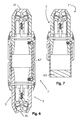
- Figure 6 shows a module 1' with two coaxial heads 3 that can be enabled independently of each other.
- the two heads 3 are keyed to the ends of a cylindrical connection tube 67, which could be made, for instance, of plastic or carbon fibre or aluminium.
- the magnetic stator of one of the heads 3 has a flat multipolar head surface 21 suitable for anchoring to a flat ferromagnetic surface on a magnetic or ferromagnetic module, while the magnetic stator of the other head 3 has an arched multipolar head surface 21 suitable for anchoring to a spherical magnetic or ferromagnetic module.
- the shape of the multipolar head surface of the magnetic stator can be varied at will to suit the shape of the surface to anchor, and can also be varied at will in a given magnetic module comprising more than one anchoring head 3.
- Figure 7 shows a structure with a magnetic module 1" that allows for the anchorage of another magnetic module.
- the magnetic module 1" has only one head 3 to enable, but is equipped with a ferromagnetic element 63 at the axially opposite end to said head 3.
- the outer surface of the ferromagnetic element 63 of the magnetic module 1" can be anchored by an enabled head of another magnetic module.
- the invention extends to the case of anchoring the head of a magnetic module to a ferromagnetic surface even without direct contact, with a non-ferromagnetic material between them. This may be the case, for instance, if the spherical ferromagnetic module of figure 5 were coated with a non-magnetic matrix with a high friction coefficient.
- connection tube on the heads of a magnetic module of the present invention e.g. the cylindrical tube indicated by 67 in figure 6
- the connection tube on the heads of a magnetic module of the present invention can be equipped with a telescoping connection system between the heads.
- connection tube 67 of figure 6 could be divided into two parts, each solidly attached to one head of the magnetic module and a central body with a telescoping movement and a longitudinal bayonet coupling could be inserted between these two separate parts.
- the heads of the magnetic module could thus be brought closer together to insert the magnetic module in the lattice structure, then spread further apart for its final positioning, turning the tube in order to trip the bayonet coupling.
- This solution can be provided as necessary on one, several or all of the magnetic modules.
Landscapes
- Physics & Mathematics (AREA)
- Electromagnetism (AREA)
- Engineering & Computer Science (AREA)
- Power Engineering (AREA)
- Iron Core Of Rotating Electric Machines (AREA)
- Dynamo-Electric Clutches, Dynamo-Electric Brakes (AREA)
- Electromagnets (AREA)
- Permanent Field Magnets Of Synchronous Machinery (AREA)
- Magnetic Resonance Imaging Apparatus (AREA)
- Switches That Are Operated By Magnetic Or Electric Fields (AREA)
- Permanent Magnet Type Synchronous Machine (AREA)
- Coupling Device And Connection With Printed Circuit (AREA)
Applications Claiming Priority (3)
| Application Number | Priority Date | Filing Date | Title |
|---|---|---|---|
| ITMI20011394 | 2001-06-29 | ||
| IT2001MI001394A ITMI20011394A1 (it) | 2001-06-29 | 2001-06-29 | Modulo ad ancoraggio mafnetico con sistema di attivazione/disattivazione e regolazione della forza magnetica di ancoraggio e relativi assiem |
| PCT/EP2002/006944 WO2003003388A1 (en) | 2001-06-29 | 2002-06-24 | Magnetic anchoring module with a system for enabling/disabling and adjusting the magnetic anchoring force and related assemblies |
Publications (2)
| Publication Number | Publication Date |
|---|---|
| EP1399933A1 EP1399933A1 (en) | 2004-03-24 |
| EP1399933B1 true EP1399933B1 (en) | 2011-09-14 |
Family
ID=11447977
Family Applications (1)
| Application Number | Title | Priority Date | Filing Date |
|---|---|---|---|
| EP02758263A Expired - Lifetime EP1399933B1 (en) | 2001-06-29 | 2002-06-24 | Magnetic anchoring module with a system for enabling/disabling and adjusting the magnetic anchoring force |
Country Status (11)
Families Citing this family (19)
| Publication number | Priority date | Publication date | Assignee | Title |
|---|---|---|---|---|
| DE20202183U1 (de) * | 2002-02-01 | 2002-06-06 | Kretzschmar, Michael, Dr., 22453 Hamburg | Baukasten |
| US7273404B2 (en) * | 2004-01-16 | 2007-09-25 | Mega Brands America, Inc. | Magnetic construction modules for creating three-dimensional assemblies |
| US7234986B2 (en) * | 2004-01-16 | 2007-06-26 | Mega Brands America, Inc. | Magnetic construction kit with wheel-like components |
| US20050159076A1 (en) * | 2004-01-16 | 2005-07-21 | Kowalski Charles J. | Magnetic construction module with interchangeable magnet holders |
| US20060084300A1 (en) * | 2004-10-15 | 2006-04-20 | Kowalski Charles J | Magnetic construction kit adapted for use with construction blocks |
| WO2006044636A2 (en) * | 2004-10-15 | 2006-04-27 | Mega Brands International, Luxembourg, Zug Branch | Illuminated, three-dimensional modules for a magnetic toy construction kit |
| US7322873B2 (en) * | 2004-10-19 | 2008-01-29 | Mega Brands America, Inc. | Illuminated, three-dimensional modules with coaxial magnetic connectors for a toy construction kit |
| US20060137270A1 (en) * | 2004-12-10 | 2006-06-29 | Parvis Daftari | Magnetic toy construction modules with side-mounted magnets |
| US7955155B2 (en) * | 2007-07-09 | 2011-06-07 | Mega Brands International | Magnetic and electronic toy construction systems and elements |
| US7944334B2 (en) * | 2008-07-14 | 2011-05-17 | Magnasphere Corp. | Tamper-resistant alarm switch assembly |
| US8747045B2 (en) * | 2009-11-03 | 2014-06-10 | National Oilwell Varco, L.P. | Pipe stabilizer for pipe section guide system |
| US20140263915A1 (en) * | 2013-03-12 | 2014-09-18 | Robert Henry Bernacki | Rapid Deploy Manually Operated Extendible Strut |
| US10532150B2 (en) * | 2014-07-21 | 2020-01-14 | Medtronic Minimed, Inc. | Smart connection interface |
| ITUA20164330A1 (it) * | 2016-06-13 | 2017-12-13 | Fabio Pedrini | Gruppo di galleggiante per lenza da pesca |
| WO2018152361A1 (en) | 2017-02-15 | 2018-08-23 | LaRose Industries, LLC | Rod-shaped module for toy magnetic construction kits and method for making same |
| USD903779S1 (en) | 2017-02-15 | 2020-12-01 | LaRose Industries, LLC | Toy construction element |
| IT201800006207A1 (it) * | 2018-06-11 | 2019-12-11 | Modulo magnetico con superfici di ancoraggio attivabili e disattivabili magneticamente | |
| US11224821B2 (en) | 2019-06-24 | 2022-01-18 | LaRose Industries, LLC | Shell-within-a-shell magnetic toy construction block |
| US11207609B2 (en) | 2019-06-27 | 2021-12-28 | LaRose Industries, LLC | Magnetic toy construction block with ring-type magnet |
Family Cites Families (10)
| Publication number | Priority date | Publication date | Assignee | Title |
|---|---|---|---|---|
| ITMI20010608A1 (it) | 2001-03-22 | 2002-09-22 | Claudio Vicentelli | Elemento di giunzione di moduli ad ancoraggio magnetico per la realizzazione di strutture reticolari stabili |
| JPS5578505A (en) * | 1978-12-08 | 1980-06-13 | Kanetsuu Kogyo Kk | Attraction type magnetic device |
| FR2523940A1 (fr) * | 1982-03-25 | 1983-09-30 | Braillon Cie | Appareil magnetique, notamment pour la manutention |
| DE3220801A1 (de) * | 1982-06-03 | 1984-01-26 | Max Baermann GmbH, 5060 Bergisch Gladbach | Schaltbare, dauermagnetische haltevorrichtung |
| US4492036A (en) * | 1984-01-11 | 1985-01-08 | Brown & Sharp Manufacturing Company | Magnetic ball bar gauge |
| DE4102102C2 (de) * | 1991-01-25 | 1995-09-07 | Leybold Ag | Magnetanordnung mit wenigstens zwei Permanentmagneten sowie ihre Verwendung |
| KR950006689Y1 (ko) * | 1992-12-15 | 1995-08-18 | 정형 | 자력 흡착기 |
| ITMI981109A1 (it) | 1998-05-20 | 1999-11-20 | Claudio Vicentelli | Moduli per la realizzazione di assiemi di ancoraggio magnetico e relativi assiemi |
| AUPQ446699A0 (en) * | 1999-12-06 | 2000-01-06 | Kocijan, Franz | Switchable (variable) permanent magnet device |
| JP2002315293A (ja) * | 2001-04-11 | 2002-10-25 | Nidec Copal Corp | アクチュエータ |
-
2001
- 2001-06-29 IT IT2001MI001394A patent/ITMI20011394A1/it unknown
-
2002
- 2002-06-24 RU RU2004102510/09A patent/RU2289174C2/ru not_active IP Right Cessation
- 2002-06-24 AU AU2002325263A patent/AU2002325263C1/en not_active Ceased
- 2002-06-24 WO PCT/EP2002/006944 patent/WO2003003388A1/en active Application Filing
- 2002-06-24 JP JP2003509472A patent/JP4078301B2/ja not_active Expired - Fee Related
- 2002-06-24 BR BR0210047-9A patent/BR0210047A/pt not_active IP Right Cessation
- 2002-06-24 US US10/482,023 patent/US6963261B2/en not_active Expired - Fee Related
- 2002-06-24 CN CN02812064.7A patent/CN1264173C/zh not_active Expired - Fee Related
- 2002-06-24 AT AT02758263T patent/ATE524816T1/de not_active IP Right Cessation
- 2002-06-24 CA CA002446233A patent/CA2446233A1/en not_active Abandoned
- 2002-06-24 EP EP02758263A patent/EP1399933B1/en not_active Expired - Lifetime
Also Published As
| Publication number | Publication date |
|---|---|
| ATE524816T1 (de) | 2011-09-15 |
| HK1067231A1 (en) | 2005-04-01 |
| JP2004531088A (ja) | 2004-10-07 |
| WO2003003388A1 (en) | 2003-01-09 |
| JP4078301B2 (ja) | 2008-04-23 |
| CN1264173C (zh) | 2006-07-12 |
| RU2004102510A (ru) | 2005-05-10 |
| ITMI20011394A0 (it) | 2001-06-29 |
| RU2289174C2 (ru) | 2006-12-10 |
| US6963261B2 (en) | 2005-11-08 |
| BR0210047A (pt) | 2004-08-17 |
| AU2002325263C1 (en) | 2006-08-24 |
| CA2446233A1 (en) | 2003-01-09 |
| CN1516882A (zh) | 2004-07-28 |
| ITMI20011394A1 (it) | 2002-12-29 |
| US20040164830A1 (en) | 2004-08-26 |
| EP1399933A1 (en) | 2004-03-24 |
Similar Documents
| Publication | Publication Date | Title |
|---|---|---|
| EP1399933B1 (en) | Magnetic anchoring module with a system for enabling/disabling and adjusting the magnetic anchoring force | |
| AU2002325263B2 (en) | Magnetic anchoring module with a system for enabling/disabling and adjusting the magnetic anchoring force and related assemblies | |
| AU2002325263A1 (en) | Magnetic anchoring module with a system for enabling/disabling and adjusting the magnetic anchoring force and related assemblies | |
| US5349258A (en) | Permanent magnet structure for use in electric machinery | |
| US6888272B2 (en) | Unipolar transverse magnetic flux machine | |
| JP6515454B2 (ja) | ステッピングモータ及び時計 | |
| EP2429068A1 (en) | Electric machine | |
| KR20170062889A (ko) | 전동기용 자석 조립체 | |
| MY129046A (en) | Driving apparatus, light-amount regulating apparatus, and lens driving apparatus | |
| CN112600388B (zh) | 磁齿轮组件及具有其的复合电机 | |
| US7372179B2 (en) | Stepper motor having solenoid coils around end portions of stator poles | |
| US4488069A (en) | Stepping motor | |
| US20100308675A1 (en) | External split field generator | |
| US20160329800A1 (en) | Linear motor | |
| EP0244709A1 (en) | Display or indicating device | |
| US3953750A (en) | Electric motor | |
| HK1067231B (en) | Magnetic anchoring module with a system for enabling/disabling and adjusting the magnetic anchoring force and related assemblies | |
| DE102023136676B4 (de) | Motorischer Verstellantrieb für Objektive | |
| RU2098909C1 (ru) | Электромеханический привод | |
| KR930701856A (ko) | 자기적으로 구동되는 모터 | |
| US10355540B2 (en) | Magnetic drive enhancement | |
| US8089188B2 (en) | Internal split field generator | |
| SU1649158A1 (ru) | Электромагнитна переключающа муфта | |
| JPH07227076A (ja) | 正逆回転ステッピングモータ | |
| AU2008234988B2 (en) | An Electric Motor |
Legal Events
| Date | Code | Title | Description |
|---|---|---|---|
| PUAI | Public reference made under article 153(3) epc to a published international application that has entered the european phase |
Free format text: ORIGINAL CODE: 0009012 |
|
| 17P | Request for examination filed |
Effective date: 20031125 |
|
| AK | Designated contracting states |
Kind code of ref document: A1 Designated state(s): AT BE CH CY DE DK ES FI FR GB GR IE IT LI LU MC NL PT SE TR |
|
| RAP1 | Party data changed (applicant data changed or rights of an application transferred) |
Owner name: VICENTELLI, CLAUDIO |
|
| RIN1 | Information on inventor provided before grant (corrected) |
Inventor name: VICENTELLI, CLAUDIO |
|
| 17Q | First examination report despatched |
Effective date: 20080808 |
|
| RAP1 | Party data changed (applicant data changed or rights of an application transferred) |
Owner name: VICENTELLI, CLAUDIO |
|
| RIN1 | Information on inventor provided before grant (corrected) |
Inventor name: VICENTELLI, CLAUDIO |
|
| GRAP | Despatch of communication of intention to grant a patent |
Free format text: ORIGINAL CODE: EPIDOSNIGR1 |
|
| RTI1 | Title (correction) |
Free format text: MAGNETIC ANCHORING MODULE WITH A SYSTEM FOR ENABLING/DISABLING AND ADJUSTING THE MAGNETIC ANCHORING FORCE |
|
| GRAS | Grant fee paid |
Free format text: ORIGINAL CODE: EPIDOSNIGR3 |
|
| GRAA | (expected) grant |
Free format text: ORIGINAL CODE: 0009210 |
|
| AK | Designated contracting states |
Kind code of ref document: B1 Designated state(s): AT BE CH CY DE DK ES FI FR GB GR IE IT LI LU MC NL PT SE TR |
|
| REG | Reference to a national code |
Ref country code: GB Ref legal event code: FG4D |
|
| REG | Reference to a national code |
Ref country code: CH Ref legal event code: EP |
|
| REG | Reference to a national code |
Ref country code: IE Ref legal event code: FG4D |
|
| REG | Reference to a national code |
Ref country code: DE Ref legal event code: R096 Ref document number: 60241045 Country of ref document: DE Effective date: 20111201 |
|
| REG | Reference to a national code |
Ref country code: NL Ref legal event code: VDEP Effective date: 20110914 |
|
| PG25 | Lapsed in a contracting state [announced via postgrant information from national office to epo] |
Ref country code: FI Free format text: LAPSE BECAUSE OF FAILURE TO SUBMIT A TRANSLATION OF THE DESCRIPTION OR TO PAY THE FEE WITHIN THE PRESCRIBED TIME-LIMIT Effective date: 20110914 Ref country code: SE Free format text: LAPSE BECAUSE OF FAILURE TO SUBMIT A TRANSLATION OF THE DESCRIPTION OR TO PAY THE FEE WITHIN THE PRESCRIBED TIME-LIMIT Effective date: 20110914 |
|
| PG25 | Lapsed in a contracting state [announced via postgrant information from national office to epo] |
Ref country code: AT Free format text: LAPSE BECAUSE OF FAILURE TO SUBMIT A TRANSLATION OF THE DESCRIPTION OR TO PAY THE FEE WITHIN THE PRESCRIBED TIME-LIMIT Effective date: 20110914 Ref country code: GR Free format text: LAPSE BECAUSE OF FAILURE TO SUBMIT A TRANSLATION OF THE DESCRIPTION OR TO PAY THE FEE WITHIN THE PRESCRIBED TIME-LIMIT Effective date: 20111215 Ref country code: CY Free format text: LAPSE BECAUSE OF FAILURE TO SUBMIT A TRANSLATION OF THE DESCRIPTION OR TO PAY THE FEE WITHIN THE PRESCRIBED TIME-LIMIT Effective date: 20110914 |
|
| REG | Reference to a national code |
Ref country code: AT Ref legal event code: MK05 Ref document number: 524816 Country of ref document: AT Kind code of ref document: T Effective date: 20110914 |
|
| PG25 | Lapsed in a contracting state [announced via postgrant information from national office to epo] |
Ref country code: BE Free format text: LAPSE BECAUSE OF FAILURE TO SUBMIT A TRANSLATION OF THE DESCRIPTION OR TO PAY THE FEE WITHIN THE PRESCRIBED TIME-LIMIT Effective date: 20110914 |
|
| PG25 | Lapsed in a contracting state [announced via postgrant information from national office to epo] |
Ref country code: NL Free format text: LAPSE BECAUSE OF FAILURE TO SUBMIT A TRANSLATION OF THE DESCRIPTION OR TO PAY THE FEE WITHIN THE PRESCRIBED TIME-LIMIT Effective date: 20110914 Ref country code: PT Free format text: LAPSE BECAUSE OF FAILURE TO SUBMIT A TRANSLATION OF THE DESCRIPTION OR TO PAY THE FEE WITHIN THE PRESCRIBED TIME-LIMIT Effective date: 20120116 |
|
| PLBE | No opposition filed within time limit |
Free format text: ORIGINAL CODE: 0009261 |
|
| STAA | Information on the status of an ep patent application or granted ep patent |
Free format text: STATUS: NO OPPOSITION FILED WITHIN TIME LIMIT |
|
| PG25 | Lapsed in a contracting state [announced via postgrant information from national office to epo] |
Ref country code: DK Free format text: LAPSE BECAUSE OF FAILURE TO SUBMIT A TRANSLATION OF THE DESCRIPTION OR TO PAY THE FEE WITHIN THE PRESCRIBED TIME-LIMIT Effective date: 20110914 |
|
| 26N | No opposition filed |
Effective date: 20120615 |
|
| REG | Reference to a national code |
Ref country code: DE Ref legal event code: R097 Ref document number: 60241045 Country of ref document: DE Effective date: 20120615 |
|
| PG25 | Lapsed in a contracting state [announced via postgrant information from national office to epo] |
Ref country code: MC Free format text: LAPSE BECAUSE OF NON-PAYMENT OF DUE FEES Effective date: 20120630 |
|
| REG | Reference to a national code |
Ref country code: IE Ref legal event code: MM4A |
|
| PG25 | Lapsed in a contracting state [announced via postgrant information from national office to epo] |
Ref country code: ES Free format text: LAPSE BECAUSE OF FAILURE TO SUBMIT A TRANSLATION OF THE DESCRIPTION OR TO PAY THE FEE WITHIN THE PRESCRIBED TIME-LIMIT Effective date: 20111225 Ref country code: IE Free format text: LAPSE BECAUSE OF NON-PAYMENT OF DUE FEES Effective date: 20120624 |
|
| PGFP | Annual fee paid to national office [announced via postgrant information from national office to epo] |
Ref country code: GB Payment date: 20130620 Year of fee payment: 12 Ref country code: CH Payment date: 20130620 Year of fee payment: 12 |
|
| PGFP | Annual fee paid to national office [announced via postgrant information from national office to epo] |
Ref country code: FR Payment date: 20130709 Year of fee payment: 12 |
|
| PG25 | Lapsed in a contracting state [announced via postgrant information from national office to epo] |
Ref country code: TR Free format text: LAPSE BECAUSE OF FAILURE TO SUBMIT A TRANSLATION OF THE DESCRIPTION OR TO PAY THE FEE WITHIN THE PRESCRIBED TIME-LIMIT Effective date: 20110914 |
|
| PG25 | Lapsed in a contracting state [announced via postgrant information from national office to epo] |
Ref country code: LU Free format text: LAPSE BECAUSE OF NON-PAYMENT OF DUE FEES Effective date: 20120624 |
|
| REG | Reference to a national code |
Ref country code: CH Ref legal event code: PL |
|
| GBPC | Gb: european patent ceased through non-payment of renewal fee |
Effective date: 20140624 |
|
| REG | Reference to a national code |
Ref country code: FR Ref legal event code: ST Effective date: 20150227 |
|
| PGFP | Annual fee paid to national office [announced via postgrant information from national office to epo] |
Ref country code: IT Payment date: 20141222 Year of fee payment: 13 |
|
| PG25 | Lapsed in a contracting state [announced via postgrant information from national office to epo] |
Ref country code: CH Free format text: LAPSE BECAUSE OF NON-PAYMENT OF DUE FEES Effective date: 20140630 Ref country code: LI Free format text: LAPSE BECAUSE OF NON-PAYMENT OF DUE FEES Effective date: 20140630 |
|
| PGFP | Annual fee paid to national office [announced via postgrant information from national office to epo] |
Ref country code: DE Payment date: 20141218 Year of fee payment: 13 |
|
| PG25 | Lapsed in a contracting state [announced via postgrant information from national office to epo] |
Ref country code: FR Free format text: LAPSE BECAUSE OF NON-PAYMENT OF DUE FEES Effective date: 20140630 Ref country code: GB Free format text: LAPSE BECAUSE OF NON-PAYMENT OF DUE FEES Effective date: 20140624 |
|
| REG | Reference to a national code |
Ref country code: DE Ref legal event code: R119 Ref document number: 60241045 Country of ref document: DE |
|
| PG25 | Lapsed in a contracting state [announced via postgrant information from national office to epo] |
Ref country code: IT Free format text: LAPSE BECAUSE OF NON-PAYMENT OF DUE FEES Effective date: 20150624 |
|
| PG25 | Lapsed in a contracting state [announced via postgrant information from national office to epo] |
Ref country code: DE Free format text: LAPSE BECAUSE OF NON-PAYMENT OF DUE FEES Effective date: 20160101 |