EP1398807A2 - Solid electrolytic capacitor - Google Patents
Solid electrolytic capacitor Download PDFInfo
- Publication number
- EP1398807A2 EP1398807A2 EP03018404A EP03018404A EP1398807A2 EP 1398807 A2 EP1398807 A2 EP 1398807A2 EP 03018404 A EP03018404 A EP 03018404A EP 03018404 A EP03018404 A EP 03018404A EP 1398807 A2 EP1398807 A2 EP 1398807A2
- Authority
- EP
- European Patent Office
- Prior art keywords
- layer
- plated layer
- electrolytic capacitor
- solid electrolytic
- metal
- Prior art date
- Legal status (The legal status is an assumption and is not a legal conclusion. Google has not performed a legal analysis and makes no representation as to the accuracy of the status listed.)
- Granted
Links
Images

Classifications
-
- H—ELECTRICITY
- H01—ELECTRIC ELEMENTS
- H01G—CAPACITORS; CAPACITORS, RECTIFIERS, DETECTORS, SWITCHING DEVICES, LIGHT-SENSITIVE OR TEMPERATURE-SENSITIVE DEVICES OF THE ELECTROLYTIC TYPE
- H01G9/00—Electrolytic capacitors, rectifiers, detectors, switching devices, light-sensitive or temperature-sensitive devices; Processes of their manufacture
- H01G9/004—Details
- H01G9/04—Electrodes or formation of dielectric layers thereon
- H01G9/048—Electrodes or formation of dielectric layers thereon characterised by their structure
-
- H—ELECTRICITY
- H01—ELECTRIC ELEMENTS
- H01G—CAPACITORS; CAPACITORS, RECTIFIERS, DETECTORS, SWITCHING DEVICES, LIGHT-SENSITIVE OR TEMPERATURE-SENSITIVE DEVICES OF THE ELECTROLYTIC TYPE
- H01G9/00—Electrolytic capacitors, rectifiers, detectors, switching devices, light-sensitive or temperature-sensitive devices; Processes of their manufacture
- H01G9/004—Details
- H01G9/008—Terminals
- H01G9/012—Terminals specially adapted for solid capacitors
-
- H—ELECTRICITY
- H01—ELECTRIC ELEMENTS
- H01G—CAPACITORS; CAPACITORS, RECTIFIERS, DETECTORS, SWITCHING DEVICES, LIGHT-SENSITIVE OR TEMPERATURE-SENSITIVE DEVICES OF THE ELECTROLYTIC TYPE
- H01G9/00—Electrolytic capacitors, rectifiers, detectors, switching devices, light-sensitive or temperature-sensitive devices; Processes of their manufacture
- H01G9/004—Details
- H01G9/022—Electrolytes; Absorbents
- H01G9/025—Solid electrolytes
- H01G9/028—Organic semiconducting electrolytes, e.g. TCNQ
-
- H—ELECTRICITY
- H01—ELECTRIC ELEMENTS
- H01G—CAPACITORS; CAPACITORS, RECTIFIERS, DETECTORS, SWITCHING DEVICES, LIGHT-SENSITIVE OR TEMPERATURE-SENSITIVE DEVICES OF THE ELECTROLYTIC TYPE
- H01G9/00—Electrolytic capacitors, rectifiers, detectors, switching devices, light-sensitive or temperature-sensitive devices; Processes of their manufacture
- H01G9/004—Details
- H01G9/04—Electrodes or formation of dielectric layers thereon
-
- H—ELECTRICITY
- H01—ELECTRIC ELEMENTS
- H01G—CAPACITORS; CAPACITORS, RECTIFIERS, DETECTORS, SWITCHING DEVICES, LIGHT-SENSITIVE OR TEMPERATURE-SENSITIVE DEVICES OF THE ELECTROLYTIC TYPE
- H01G9/00—Electrolytic capacitors, rectifiers, detectors, switching devices, light-sensitive or temperature-sensitive devices; Processes of their manufacture
- H01G9/004—Details
- H01G9/04—Electrodes or formation of dielectric layers thereon
- H01G9/042—Electrodes or formation of dielectric layers thereon characterised by the material
-
- H—ELECTRICITY
- H01—ELECTRIC ELEMENTS
- H01G—CAPACITORS; CAPACITORS, RECTIFIERS, DETECTORS, SWITCHING DEVICES, LIGHT-SENSITIVE OR TEMPERATURE-SENSITIVE DEVICES OF THE ELECTROLYTIC TYPE
- H01G9/00—Electrolytic capacitors, rectifiers, detectors, switching devices, light-sensitive or temperature-sensitive devices; Processes of their manufacture
- H01G9/004—Details
- H01G9/04—Electrodes or formation of dielectric layers thereon
- H01G9/042—Electrodes or formation of dielectric layers thereon characterised by the material
- H01G9/0425—Electrodes or formation of dielectric layers thereon characterised by the material specially adapted for cathode
-
- H—ELECTRICITY
- H01—ELECTRIC ELEMENTS
- H01G—CAPACITORS; CAPACITORS, RECTIFIERS, DETECTORS, SWITCHING DEVICES, LIGHT-SENSITIVE OR TEMPERATURE-SENSITIVE DEVICES OF THE ELECTROLYTIC TYPE
- H01G9/00—Electrolytic capacitors, rectifiers, detectors, switching devices, light-sensitive or temperature-sensitive devices; Processes of their manufacture
- H01G9/004—Details
- H01G9/04—Electrodes or formation of dielectric layers thereon
- H01G9/042—Electrodes or formation of dielectric layers thereon characterised by the material
- H01G9/045—Electrodes or formation of dielectric layers thereon characterised by the material based on aluminium
Definitions
- the present invention relates to a solid electrolytic capacitor, and more particularly to a solid electrolytic capacitor utilizing a conductive polymer as a solid electrolyte.
- a solid electrolytic capacitor has a configuration constituted by forming an anode with a valve-action metal such as tantalum, niobium or aluminum, oxidizing a surface of the anode to form a dielectric member, forming thereon a closely contacting layer of manganese dioxide or a conductive polymer, and forming on that layer a graphite layer or a silver paste layer as a cathode.
- a valve-action metal such as tantalum, niobium or aluminum
- the manganese dioxide or the conductive polymer constitutes a solid electrolyte, and particularly the conductive polymer is being employed frequently in recent years, as it has a high conductivity and can reduce an equivalent series resistance (ESR) of a capacitor.
- ESR equivalent series resistance
- the solid electrolytic capacitor utilizing a conductive polymer as a solid electrolyte is disclosed for example in Japanese Patent Application Laid-open No. 5-275290 (which will be hereinafter referred to as related art 1).
- an aluminum foil subjected to a surface enlargement by etching which will be referred to as an etched aluminum foil, is divided by an epoxy resin member, into a first area for connecting an external anode terminal, starting from an end in the longitudinal direction, and a second area for realizing a capacity.
- an aluminum oxide film is formed which is obtained by anodizing the aluminum foil.
- a polypyrrole layer is formed by a conductive polymer and is provided on such aluminum oxide film. On the polypyrrole layer, a graphite layer and a silver paste layer are formed in succession and in closely contacted manner.
- a basic structure of a capacitor which will be referred to as a solid electrolytic capacitor element, is formed by the aluminum foil, the aluminum oxide film, the polypyrrole layer, the graphite layer and the silver paste.
- the anode is constituted by the aluminum foil
- the dielectric member is constituted by the aluminum oxide film
- the cathode is constituted by the polypyrrole layer, the graphite layer and the silver paste.
- an external anode terminal and an external cathode terminal are mounted on the capacitor element, and an external package is provided for sealing the element and shaping the external form of the capacitor.
- the external anode terminal and the external cathode terminal are formed by a base member formed by a copper-based or iron-based metal and surfacially plated with a metal for enabling soldering.
- the external anode terminal is adjoined by an electric welding or an ultrasonic welding to the aluminum foil constituting the anode, while the external cathode terminal is electrically fixed, for example by a conductive adhesive material, to an outermost layer of the cathode.
- the conductive polymer employed in the prior solid electrolytic capacitor is associated with a drawback, though initially having a high conductivity, of losing the conductivity by being oxidized in an oxygen-containing atmosphere of a high temperature. Therefore, in case the interception of oxygen is insufficient in the cathode, ESR will be deteriorated when the solid electrolytic capacitor is exposed to a high temperature over a long period.
- the cathode is constituted by forming a graphite layer and a silver paste layer on a conductive polymer layer. The graphite layer and the silver paste layer cannot be formed densely and is therefore unable to sufficiently prevent intrusion of oxygen.
- the external cathode terminal has a solder plating or a tin plating on the surface of a base metal, in order to enable soldering thereby facilitating the mounting.
- Such plating certainly facilitates soldering, but is associated with a drawback of being partially fused in a surface adhered to the cathode of the capacitor element, thereby causing a peeling of the external cathode terminal and the conductive adhesive and increasing a contact resistance with the cathode electrode.
- a metal such as gold or silver which is higher in the melting temperature and chemically more stable than solder
- a solid electrolytic capacitor which includes an anode part having a lead wire extracted from at least an end of a metal piece having an oxide film in a part thereof, a solid electrolyte having a conductive polymer layer formed on the oxide film, and a cathode part having a conductive material layer formed on said conductive polymer layer.
- the cathode part further includes a first metal plated layer.
- the cathode part is preferably provided with the aforementioned first metal plated layer and a solderable second metal layer.
- an aluminum foil 7, subjected to a surface enlargement by etching which foil will be referred to as an etched aluminum foil, is divided by an epoxy resin member 9, from the left-hand side of the drawing, into an area for connecting an external anode terminal, and a second area for developing a capacity.
- the capacity developing area constituting a major portion of the aluminum foil 7 at the right-hand side of the drawing, there is formed an aluminum oxide film 11 obtained by anodizing the aluminum foil 7 constituting a base member.
- a basic structure of a capacitor which will hereinafter be referred to as a solid electrolytic capacitor element, is constituted by the aluminum foil 7, the aluminum oxide film 11, the polypyrrole layer 13, the graphite layer 15 and the silver paste layer 17.
- the aluminum foil 7 serves as an anode electrode
- the aluminum oxide film 11 constitutes a dielectric member
- the polypyrrole layer 13, the graphite layer 15 and the silver paste layer 17 constitute a cathode electrodes.
- an external anode terminal 19 and an external cathode terminal 21 are mounted for electrical connection with the exterior, and an external package 23 is provided in order to seal the element and to shape an external form of the capacitor.
- the external anode terminal 19 and the external cathode terminal 21 are formed by a base member formed by a copper-based or iron-based metal and surfacially plated with a solderable metal.
- the external anode terminal 19 is adjoined by an electric welding or an ultrasonic welding to the aluminum foil 7 constituting the anode electrode, while the external cathode terminal 21 is electrically fixed, for example by a conductive adhesive material (not illustrated), to an outermost layer of the cathode electrode.
- an aluminum foil 27 is provided for serving as an anode and is subjected to a surface enlargement by an etching.
- an aqueous solution of hydrochloric acid is employed as an etching solution.
- a first area serves as a capacity developing area occupying a major portion at the right-hand side in Fig. 2, and is anodized to form a film 29 of aluminum oxide (Al 2 O 3 ).
- Al 2 O 3 aluminum oxide
- anodizing use is made of, for example, an aqueous solution of an ammonium salt of adipic acid, citric acid or phosphoric acid.
- a conductive polymer layer 31 of polypyrrole is formed as a solid electrolyte, and then a graphite layer 33 is formed thereon.
- the graphite layer 33 and an anode-constituting part of the aluminum foil 27 are subjected to a plating process to form a plated layer 35, and then to a formation of a solder layer 37.
- the intrusion of oxygen from the exterior can be securely prevented in comparison with a prior element.
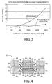
- This test is a high-temperature standing test, in which a sample is let to stand in an environment of a temperature of 125°C and electric characteristics of the sample is measured with the lapse of time.
- ESR equivalent serial resistance
- both a sample of the first embodiment, represented by a curve 45, and a sample of the prior technology represented by a curve 43 showed approximately same initial values of about 3 m ⁇ prior to the start of the test.
- the capacitor of the prior technology and the capacitor of the present embodiment provided approximately same curves for about initial 50 hours.
- the ESR of the capacitor of the prior technology, represented by the curve 43 started to show an increasing tendency, thus being separated from the curve of the capacitor of the present embodiment, represented by the curve 45.
- the capacitor of the present embodiment represented by the curve 45, showed an ESR of about 6 m ⁇ which was about twice of the initial value, while the prior capacitor represented by the curve 43 showed an increase in ESR to about 30 m ⁇ which was as high as about 10 times of the initial value.
- the high sealing power of the capacitor of the present embodiment brings about a significant effect in improving the time-dependent deterioration of ESR and the stability of characteristics and in achieving a high reliability and a longer service life, particularly when a conductive polymer having a tendency to lower the conductivity at presence of oxygen is used as a solid electrolyte.
- the plated metal for the plated metal, use can be made of, for example copper, nickel, silver or gold. Also for plating, use can be made of an electrolytic plating method or a non-electrolytic plating method.
- the solder layer can be formed either by a solder plating method, a tin plating method etc., or by a method of immersion in a fused solder tank.
- the present first embodiment employs polypyrrole, obtained by a chemical oxidation polymerization of a pyrrole monomer, as the conductive polymer, but there can also be employed other materials such as polythiophene or polyaniline. Also the method of forming a polymer is not limited to a chemical oxidation polymerization but an electrolytic oxidation polymerization may be employed for this purpose.
- a solid electrolytic capacitor 51 according to the second embodiment of the invention includes a solid electrolytic capacitor element 63 which is obtained by forming, in a predetermined portion of an etched aluminum foil (as a valve action metal) 53 formed by an etching in an etching aqueous solution for example of hydrochloric acid, an aluminum oxide film 55 in an aqueous processing solution of an ammonium of adipic acid, citric acid, phosphoric acid etc., then coating and hardening an insulating resin 57 thereby forming a masking, and forming a conductive polymer layer 59 and a graphite layer 61 in succession on a predetermined portion of the aluminum oxide film 55.
- a metal plating is applied on the graphite layer 61 and on anode parts 65 provided on both ends of the solid electrolytic capacitor element 63, thereby forming a plated layer 67 except for the portion of the insulating resin 57 formed in advance.
- a solid electrolytic capacitor is completed by forming a solder layer 69 on the plated layer 67 of the element 63 and the anode part 65.
- the aluminum solid electrolytic capacitor 51 of the second embodiment of the invention is a solid electrolytic capacitor of so-called three-terminal structure, and can prevent intrusion of oxygen, moisture etc. from the exterior by forming a dense metal layer on the external periphery of the element similarly to the first embodiment.
- the present invention is applicable also to a solid electrolytic capacitor utilizing another valve action metal such as tantalum or niobium as the anode.
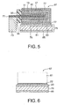
- a solid electrolytic capacitor 97 according to the third embodiment of the invention employs a cathode part of the solid electrolytic element 81 of a structure same as that in the prior art.
- an external anode terminal 73 is mounted in a portion of an aluminum foil 71, made available for mounting the external anode terminal.
- the external anode terminal 73 is formed by a solderable material, such as a 42 alloy or a copper plate, on which a solder plating is applied. It is adjoined to the aluminum foil 71 for example by an ultrasonic welding or an electric resistance welding.
- an external cathode terminal 75 is adhered to the cathode part with a conductive adhesive 77 such as a silver paste.
- the external cathode terminal 75 has a cathode terminal metal 79, such as a 42 alloy, copper or iron, which has a cathode-connecting surface plated layer 83 such as a gold plated layer or a silver plated layer on a surface to be adjoined to the element 81, and a mounting surface plated layer 85 that can be soldered, such as a solder plating or a tin plating, on the other surface.
- an adjoining through a silver plated layer or a gold plated layer which is chemically similar to the silver paste constituting the conductive adhesive, achieves chemical stability, and such plating, having a higher melting temperature than in the solder, is not fused at the mounting operation there by maintaining the adjoining interface in a stable state.
- the first or second embodiment may be used in combination with the third embodiment.
- a metal plated layer is provided in the cathode part of the solid electrolytic capacitor thereby preventing intrusion of oxygen and suppressing the deterioration of the characteristics of the conductive polymer. Also a gold plated layer or a silver plated layer is provided in the surface of the external cathode terminal, for adjoining with the capacitor element, thereby avoiding a change in the equivalent serial resistance in the mounted state.
Landscapes
- Engineering & Computer Science (AREA)
- Power Engineering (AREA)
- Microelectronics & Electronic Packaging (AREA)
- Chemical & Material Sciences (AREA)
- Chemical Kinetics & Catalysis (AREA)
- Electrochemistry (AREA)
- Materials Engineering (AREA)
- Fixed Capacitors And Capacitor Manufacturing Machines (AREA)
- Electroplating Methods And Accessories (AREA)
Abstract
Description
Claims (9)
- A solid electrolytic capacitor comprising:wherein said cathode part further includes a first metal plated layer.an anode part having a lead wire extracted from at least an end of a metal piece having an oxide film in a part thereof;a solid electrolyte having a conductive polymer layer formed on said oxide film; anda cathode part having a conductive material layer formed on said conductive polymer layer;
- A solid electrolytic capacitor according to claim 1, wherein said cathode part further includes a solderable second metal layer formed on said first metal plated layer.
- A solid electrolytic capacitor according to claim 1 or 2, wherein said first metal plated layer comprises at least one of a copper plated layer, a nickel plated layer, a gold plated layer, and a silver plated layer.
- A solid electrolytic capacitor according to claim 2 or 3, wherein said second metal layer comprises at least one of a solder layer, a tin layer and a solderable silver paste layer.
- A solid electrolytic capacitor according to claim 1 or 2, said capacitor being a solid electrolytic capacitor of surface mounting type employing said conductive polymer as a solid electrolyte, and further comprising a cathode terminal connected to said cathode part, wherein said cathode terminal comprises a solderable third metal plated layer on a mounting surface of said cathode terminal and a fourth metal plated layer on a surface of said cathode terminal to be adjoined to said cathode part, said forth metal plated layer having a higher melting temperature than in said third metal plated layer and being chemically stable, preferably wherein said third metal plated layer comprises at least one of a solder plated layer and a tin plated layer and/or said fourth metal plated layer comprises at least one of a gold plated layer and a silver plated layer.
- A solid electrolytic capacitor according to any one of claims 1 to 5, wherein said cathode part comprises a graphite layer formed on said conductive polymer layer ard a silver paste formed on said graphite layer.
- A solid electrolytic capacitor according to any one of claims 1 to 6, wherein said metal piece of said anode part comprises aluminum, said oxide film containing aluminum oxide.
- A solid electrolytic capacitor according to any one of claims 1 to 7, wherein an insulating resin is provided around a boundary between a central part and an anoce part of said metal piece and divides said metal piece into a first area for developing a capacitance and a second area to be connected to the external anode terminal.
- A solid electrolyte capacitor according to any one of claims 1 to 8, wherein said anode part is formed on both ends constituting a part of said metal piece.
Applications Claiming Priority (2)
| Application Number | Priority Date | Filing Date | Title |
|---|---|---|---|
| JP2002248011 | 2002-08-28 | ||
| JP2002248011A JP2004087872A (en) | 2002-08-28 | 2002-08-28 | Solid electrolytic capacitor |
Publications (3)
| Publication Number | Publication Date |
|---|---|
| EP1398807A2 true EP1398807A2 (en) | 2004-03-17 |
| EP1398807A3 EP1398807A3 (en) | 2006-08-30 |
| EP1398807B1 EP1398807B1 (en) | 2016-10-26 |
Family
ID=31884689
Family Applications (1)
| Application Number | Title | Priority Date | Filing Date |
|---|---|---|---|
| EP03018404.8A Expired - Lifetime EP1398807B1 (en) | 2002-08-28 | 2003-08-13 | Solid electrolytic capacitor |
Country Status (6)
| Country | Link |
|---|---|
| US (1) | US6865070B2 (en) |
| EP (1) | EP1398807B1 (en) |
| JP (1) | JP2004087872A (en) |
| KR (1) | KR20040019926A (en) |
| CN (1) | CN100470694C (en) |
| TW (1) | TWI248097B (en) |
Families Citing this family (15)
| Publication number | Priority date | Publication date | Assignee | Title |
|---|---|---|---|---|
| DE10360892A1 (en) * | 2003-12-19 | 2005-07-21 | Robert Bosch Gmbh | Method and device for wear detection in control units |
| JP2006040938A (en) | 2004-07-22 | 2006-02-09 | Nec Tokin Corp | Solid electrolytic capacitor, laminated capacitor using the same and its manufacturing method |
| JP2006269571A (en) * | 2005-03-23 | 2006-10-05 | Sanyo Electric Co Ltd | Solid electrolytic capacitor and its manufacturing method |
| US7268997B2 (en) * | 2005-08-29 | 2007-09-11 | Takeshi Saitou | Solid electrolytic capacitor |
| JP4662368B2 (en) * | 2006-06-22 | 2011-03-30 | Necトーキン株式会社 | Manufacturing method of solid electrolytic capacitor |
| JP2010278343A (en) * | 2009-05-29 | 2010-12-09 | Sanyo Electric Co Ltd | Solid electrolytic capacitor, electronic apparatus using the same, and method of manufacturing the solid electrolytic capacitor |
| US9748043B2 (en) * | 2010-05-26 | 2017-08-29 | Kemet Electronics Corporation | Method of improving electromechanical integrity of cathode coating to cathode termination interfaces in solid electrolytic capacitors |
| CN101996774B (en) * | 2010-11-09 | 2016-01-27 | 钰邦电子(无锡)有限公司 | There is stack-type solid electrolytic capacitor and the manufacture method thereof of multi-spot welding structure |
| KR101240788B1 (en) * | 2010-11-15 | 2013-03-11 | 삼성전기주식회사 | Condenser element and method for manufacturing the same |
| TWI480907B (en) * | 2012-07-25 | 2015-04-11 | Apaq Technology Co Ltd | Winding-type solid electrolytic capacitor package structure |
| JP6393281B2 (en) * | 2013-02-19 | 2018-09-19 | ケメット エレクトロニクス コーポレーション | Method for manufacturing a solid electrolytic capacitor |
| JP6341654B2 (en) | 2013-12-04 | 2018-06-13 | 株式会社トーキン | Solid electrolytic capacitor |
| WO2017010200A1 (en) * | 2015-07-10 | 2017-01-19 | 株式会社村田製作所 | Capacitor |
| CN108281281A (en) * | 2017-12-12 | 2018-07-13 | 湖南艾华集团股份有限公司 | Piece type solid capacitor and manufacturing method |
| KR102281451B1 (en) | 2019-10-16 | 2021-07-27 | 삼성전기주식회사 | All solid battery |
Family Cites Families (12)
| Publication number | Priority date | Publication date | Assignee | Title |
|---|---|---|---|---|
| JPS5683020A (en) * | 1979-12-11 | 1981-07-07 | Matsushita Electric Industrial Co Ltd | Solidstate electrolytic condenser |
| JPS62293608A (en) * | 1986-06-12 | 1987-12-21 | 日本電気株式会社 | Manufacture of solid electrolytic capacitor |
| US5005107A (en) * | 1988-12-07 | 1991-04-02 | Matsushita Electric Industrial Co., Ltd. | Solid electrolytic capacitor |
| JPH0521279A (en) * | 1991-07-10 | 1993-01-29 | Matsushita Electric Ind Co Ltd | Capacitor and manufacturing method thereof |
| JP2876843B2 (en) * | 1991-09-13 | 1999-03-31 | 松下電器産業株式会社 | Capacitor and method of manufacturing the same |
| US5424907A (en) * | 1992-02-21 | 1995-06-13 | Matsushita Electric Industrial Co., Ltd. | Solid electrolytic capacitors and method for manufacturing the same |
| JP3463692B2 (en) | 1992-03-24 | 2003-11-05 | 昭和電工株式会社 | Manufacturing method of chip-shaped solid electrolytic capacitor |
| JPH08273983A (en) * | 1995-03-31 | 1996-10-18 | Nitsuko Corp | Aluminum solid capacitor |
| JP4036985B2 (en) * | 1998-10-26 | 2008-01-23 | 三洋電機株式会社 | Solid electrolytic capacitor |
| US6552896B1 (en) * | 1999-10-28 | 2003-04-22 | Matsushita Electric Industrial Co., Ltd. | Solid electrolytic capacitor and method for manufacturing the same |
| US6324051B1 (en) * | 1999-10-29 | 2001-11-27 | Matsushita Electric Industrial Co., Ltd. | Solid electrolytic capacitor |
| JP2002134360A (en) * | 2000-10-24 | 2002-05-10 | Matsushita Electric Ind Co Ltd | Solid electrolytic capacitor and method of manufacturing the same |
-
2002
- 2002-08-28 JP JP2002248011A patent/JP2004087872A/en active Pending
-
2003
- 2003-08-11 US US10/639,203 patent/US6865070B2/en not_active Expired - Lifetime
- 2003-08-13 EP EP03018404.8A patent/EP1398807B1/en not_active Expired - Lifetime
- 2003-08-14 CN CNB031278965A patent/CN100470694C/en not_active Expired - Lifetime
- 2003-08-26 KR KR1020030058990A patent/KR20040019926A/en not_active Ceased
- 2003-08-26 TW TW092123378A patent/TWI248097B/en not_active IP Right Cessation
Also Published As
| Publication number | Publication date |
|---|---|
| US20040042157A1 (en) | 2004-03-04 |
| TWI248097B (en) | 2006-01-21 |
| KR20040019926A (en) | 2004-03-06 |
| CN100470694C (en) | 2009-03-18 |
| CN1484262A (en) | 2004-03-24 |
| EP1398807B1 (en) | 2016-10-26 |
| US6865070B2 (en) | 2005-03-08 |
| JP2004087872A (en) | 2004-03-18 |
| TW200406795A (en) | 2004-05-01 |
| EP1398807A3 (en) | 2006-08-30 |
Similar Documents
| Publication | Publication Date | Title |
|---|---|---|
| US6865070B2 (en) | Solid electrolytic capacitor | |
| US20090116173A1 (en) | Solid electrolytic capacitor | |
| US6661645B1 (en) | Solid electrolytic capacitor and manufacturing method thereof | |
| JP4010447B2 (en) | Solid electrolytic capacitor and manufacturing method thereof | |
| JP2004055699A (en) | Solid electrolytic capacitor and its manufacturing method | |
| US20090237865A1 (en) | Solid electrolytic capacitor and method for manufacturing same | |
| JP6223800B2 (en) | Method for forming solid electrolytic capacitor | |
| JP2003045753A (en) | Multilayer solid electrolytic capacitors | |
| JP2000340463A (en) | Solid electrolytic capacitors | |
| JP3543489B2 (en) | Solid electrolytic capacitors | |
| JP4588630B2 (en) | Manufacturing method of chip-shaped solid electrolytic capacitor | |
| JP2850823B2 (en) | Manufacturing method of chip type solid electrolytic capacitor | |
| JP2001126958A (en) | Chip-type solid electrolytic capacitor | |
| JPH0794369A (en) | Solid electrolytic capacitor | |
| JP3433478B2 (en) | Solid electrolytic capacitors | |
| CN117413331A (en) | Solid electrolytic capacitor and manufacturing method of solid electrolytic capacitor | |
| JP2008078312A (en) | Solid electrolytic capacitor | |
| JPH10289838A (en) | Solid state electrolytic capacitor | |
| US20250191852A1 (en) | Solid electrolytic capacitor and production method for solid electrolytic capacitor | |
| US20230268135A1 (en) | Solid electrolytic capacitor and method for manufacturing solid electrolytic capacitor | |
| JPH10335187A (en) | Solid electrolytic capacitor and method of manufacturing the same | |
| JP4574544B2 (en) | Solid electrolytic capacitor | |
| JPH1187180A (en) | Manufacture of solid electrolytic capacitor | |
| JP3433479B2 (en) | Method for manufacturing solid electrolytic capacitor | |
| JP2895907B2 (en) | Solid electrolytic capacitor and method of manufacturing the same |
Legal Events
| Date | Code | Title | Description |
|---|---|---|---|
| PUAI | Public reference made under article 153(3) epc to a published international application that has entered the european phase |
Free format text: ORIGINAL CODE: 0009012 |
|
| AK | Designated contracting states |
Kind code of ref document: A2 Designated state(s): AT BE BG CH CY CZ DE DK EE ES FI FR GB GR HU IE IT LI LU MC NL PT RO SE SI SK TR |
|
| AX | Request for extension of the european patent |
Extension state: AL LT LV MK |
|
| PUAL | Search report despatched |
Free format text: ORIGINAL CODE: 0009013 |
|
| RIC1 | Information provided on ipc code assigned before grant |
Ipc: H01G 9/04 20060101AFI20040127BHEP Ipc: H01G 9/012 20060101ALI20060714BHEP |
|
| AK | Designated contracting states |
Kind code of ref document: A3 Designated state(s): AT BE BG CH CY CZ DE DK EE ES FI FR GB GR HU IE IT LI LU MC NL PT RO SE SI SK TR |
|
| AX | Request for extension of the european patent |
Extension state: AL LT LV MK |
|
| 17P | Request for examination filed |
Effective date: 20061211 |
|
| AKX | Designation fees paid |
Designated state(s): DE FR GB |
|
| 17Q | First examination report despatched |
Effective date: 20110413 |
|
| GRAP | Despatch of communication of intention to grant a patent |
Free format text: ORIGINAL CODE: EPIDOSNIGR1 |
|
| INTG | Intention to grant announced |
Effective date: 20160517 |
|
| GRAS | Grant fee paid |
Free format text: ORIGINAL CODE: EPIDOSNIGR3 |
|
| GRAA | (expected) grant |
Free format text: ORIGINAL CODE: 0009210 |
|
| AK | Designated contracting states |
Kind code of ref document: B1 Designated state(s): DE FR GB |
|
| REG | Reference to a national code |
Ref country code: GB Ref legal event code: FG4D Ref country code: DE Ref legal event code: R081 Ref document number: 60349531 Country of ref document: DE Owner name: TOKIN CORPORATION, SENDAI-SHI, JP Free format text: FORMER OWNER: NEC TOKIN CORP., SENDAI, MIYAGI, JP |
|
| REG | Reference to a national code |
Ref country code: DE Ref legal event code: R096 Ref document number: 60349531 Country of ref document: DE |
|
| REG | Reference to a national code |
Ref country code: FR Ref legal event code: PLFP Year of fee payment: 15 |
|
| REG | Reference to a national code |
Ref country code: FR Ref legal event code: CD Owner name: TOKIN CORPORATION, JP Effective date: 20170615 |
|
| REG | Reference to a national code |
Ref country code: DE Ref legal event code: R097 Ref document number: 60349531 Country of ref document: DE |
|
| PLBE | No opposition filed within time limit |
Free format text: ORIGINAL CODE: 0009261 |
|
| STAA | Information on the status of an ep patent application or granted ep patent |
Free format text: STATUS: NO OPPOSITION FILED WITHIN TIME LIMIT |
|
| 26N | No opposition filed |
Effective date: 20170727 |
|
| REG | Reference to a national code |
Ref country code: DE Ref legal event code: R082 Ref document number: 60349531 Country of ref document: DE Representative=s name: PRUEFER & PARTNER MBB PATENTANWAELTE RECHTSANW, DE Ref country code: DE Ref legal event code: R081 Ref document number: 60349531 Country of ref document: DE Owner name: TOKIN CORPORATION, SENDAI-SHI, JP Free format text: FORMER OWNER: NEC TOKIN CORPORATION, SENDAI-SHI, MIYAGI, JP |
|
| REG | Reference to a national code |
Ref country code: FR Ref legal event code: PLFP Year of fee payment: 16 |
|
| PGFP | Annual fee paid to national office [announced via postgrant information from national office to epo] |
Ref country code: DE Payment date: 20200729 Year of fee payment: 18 Ref country code: FR Payment date: 20200715 Year of fee payment: 18 Ref country code: GB Payment date: 20200818 Year of fee payment: 18 |
|
| REG | Reference to a national code |
Ref country code: DE Ref legal event code: R119 Ref document number: 60349531 Country of ref document: DE |
|
| GBPC | Gb: european patent ceased through non-payment of renewal fee |
Effective date: 20210813 |
|
| PG25 | Lapsed in a contracting state [announced via postgrant information from national office to epo] |
Ref country code: GB Free format text: LAPSE BECAUSE OF NON-PAYMENT OF DUE FEES Effective date: 20210813 Ref country code: FR Free format text: LAPSE BECAUSE OF NON-PAYMENT OF DUE FEES Effective date: 20210831 Ref country code: DE Free format text: LAPSE BECAUSE OF NON-PAYMENT OF DUE FEES Effective date: 20220301 |