EP1398563A1 - Power supply and mounting module for light-emitting diode - Google Patents
Power supply and mounting module for light-emitting diode Download PDFInfo
- Publication number
- EP1398563A1 EP1398563A1 EP03292243A EP03292243A EP1398563A1 EP 1398563 A1 EP1398563 A1 EP 1398563A1 EP 03292243 A EP03292243 A EP 03292243A EP 03292243 A EP03292243 A EP 03292243A EP 1398563 A1 EP1398563 A1 EP 1398563A1
- Authority
- EP
- European Patent Office
- Prior art keywords
- light
- emitting diode
- module
- connector
- housing
- Prior art date
- Legal status (The legal status is an assumption and is not a legal conclusion. Google has not performed a legal analysis and makes no representation as to the accuracy of the status listed.)
- Granted
Links
Images
Classifications
-
- F—MECHANICAL ENGINEERING; LIGHTING; HEATING; WEAPONS; BLASTING
- F21—LIGHTING
- F21S—NON-PORTABLE LIGHTING DEVICES; SYSTEMS THEREOF; VEHICLE LIGHTING DEVICES SPECIALLY ADAPTED FOR VEHICLE EXTERIORS
- F21S43/00—Signalling devices specially adapted for vehicle exteriors, e.g. brake lamps, direction indicator lights or reversing lights
- F21S43/50—Signalling devices specially adapted for vehicle exteriors, e.g. brake lamps, direction indicator lights or reversing lights characterised by aesthetic components not otherwise provided for, e.g. decorative trim, partition walls or covers
- F21S43/51—Attachment thereof
-
- F—MECHANICAL ENGINEERING; LIGHTING; HEATING; WEAPONS; BLASTING
- F21—LIGHTING
- F21S—NON-PORTABLE LIGHTING DEVICES; SYSTEMS THEREOF; VEHICLE LIGHTING DEVICES SPECIALLY ADAPTED FOR VEHICLE EXTERIORS
- F21S43/00—Signalling devices specially adapted for vehicle exteriors, e.g. brake lamps, direction indicator lights or reversing lights
- F21S43/10—Signalling devices specially adapted for vehicle exteriors, e.g. brake lamps, direction indicator lights or reversing lights characterised by the light source
- F21S43/13—Signalling devices specially adapted for vehicle exteriors, e.g. brake lamps, direction indicator lights or reversing lights characterised by the light source characterised by the type of light source
- F21S43/14—Light emitting diodes [LED]
-
- F—MECHANICAL ENGINEERING; LIGHTING; HEATING; WEAPONS; BLASTING
- F21—LIGHTING
- F21S—NON-PORTABLE LIGHTING DEVICES; SYSTEMS THEREOF; VEHICLE LIGHTING DEVICES SPECIALLY ADAPTED FOR VEHICLE EXTERIORS
- F21S43/00—Signalling devices specially adapted for vehicle exteriors, e.g. brake lamps, direction indicator lights or reversing lights
- F21S43/10—Signalling devices specially adapted for vehicle exteriors, e.g. brake lamps, direction indicator lights or reversing lights characterised by the light source
- F21S43/19—Attachment of light sources or lamp holders
- F21S43/195—Details of lamp holders, terminals or connectors
-
- F—MECHANICAL ENGINEERING; LIGHTING; HEATING; WEAPONS; BLASTING
- F21—LIGHTING
- F21S—NON-PORTABLE LIGHTING DEVICES; SYSTEMS THEREOF; VEHICLE LIGHTING DEVICES SPECIALLY ADAPTED FOR VEHICLE EXTERIORS
- F21S43/00—Signalling devices specially adapted for vehicle exteriors, e.g. brake lamps, direction indicator lights or reversing lights
- F21S43/20—Signalling devices specially adapted for vehicle exteriors, e.g. brake lamps, direction indicator lights or reversing lights characterised by refractors, transparent cover plates, light guides or filters
- F21S43/26—Refractors, transparent cover plates, light guides or filters not provided in groups F21S43/235 - F21S43/255
-
- H—ELECTRICITY
- H01—ELECTRIC ELEMENTS
- H01R—ELECTRICALLY-CONDUCTIVE CONNECTIONS; STRUCTURAL ASSOCIATIONS OF A PLURALITY OF MUTUALLY-INSULATED ELECTRICAL CONNECTING ELEMENTS; COUPLING DEVICES; CURRENT COLLECTORS
- H01R33/00—Coupling devices specially adapted for supporting apparatus and having one part acting as a holder providing support and electrical connection via a counterpart which is structurally associated with the apparatus, e.g. lamp holders; Separate parts thereof
- H01R33/05—Two-pole devices
- H01R33/46—Two-pole devices for bayonet type base
- H01R33/465—Two-pole devices for bayonet type base secured to structure or printed circuit board
Definitions
- the present invention relates generally to lighting or lighting devices. signaling, whose light sources are incandescent, and which one wishes to change by light sources of the light-emitting diode type.
- Such a situation can for example be encountered in lighting or lighting devices.
- signaling of motor vehicles such lighting or signaling devices comprising incandescent light sources alone or associated with sources made up of light-emitting diodes.
- Light-emitting diodes have, in known manner, a long service life higher than that of incandescent sources.
- the use of diodes light-emitting allows to take advantage of their small footprint to achieve relatively compact lighting or signaling devices.
- the low heat generation caused by the operation of light emitting diodes allows for example to use in their immediate environment plastics, whereas incandescent or halogen lamps would impose under the same conditions the use of materials capable of withstanding high temperatures. This therefore results in a reduced size and cost.
- incandescent sources with diodes electroluminescent, but it is then necessary to profoundly modify the structure of the lighting or signaling device to be able to do so.
- the devices lighting or signaling must emit, depending on the lighting or signaling in which the incandescent source is used, a light beam whose photometry is defined by law. Simply replacing a source at incandescent by a light emitting diode will then result in the beam light will no longer have regulatory photometry.
- the lighting or signaling device includes both incandescent sources and light emitting diodes to perform different functions. By construction, it is then necessary to provide in this lighting device or signaling, two different printed circuits, one for incandescent sources, the other for light-emitting diodes, so that the light beams emitted by these different sources are regulatory.
- the present invention is placed in this context and it aims to provide a module for using a diode in a lighting or signaling device electroluminescent instead of an incandescent source, without having to rearrange completely the architecture of the lighting or signaling device, and allowing also to produce a lighting or signaling device comprising both incandescent sources and light emitting diodes, which has only one printed circuit to supply the two types of light sources.
- the present invention therefore relates to a positioning module and for supplying a light-emitting diode, the module comprising a housing forming support for at least one light-emitting diode and a power connector electric.
- the connector has the shape and dimensions of the base of a incandescent lamp, the housing and the connector being in one piece, and the diode electroluminescent being mounted on a printed circuit.
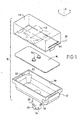
- the figures show a module for positioning and supplying a light emitting diode, this module being designated as a whole by the reference 10.
- the module includes a housing 12 forming a support for at least one light-emitting diode 14, two such diodes having been shown in FIG. 1.
- the diodes 14 are mounted on a printed circuit 16, the outer periphery of which complements the shape of the wall interior 18 of the housing 12.
- the housing 12 is closed by a cover 20, made of a transparent material of so as to allow the passage of the light rays emitted by the light-emitting diode 14 according to a general direction of emission X.
- the housing includes stops 22 on which the printed circuit carrying the diodes 14 abuts.
- the stops 22 can for example be obtained by shoulders 22 formed on the inner wall 18 of the case 12.
- the housing 12 also includes a power supply connector 24. From advantageously, the housing 12 and the connector 24 are in one piece, and obtained by example by injection molding of a thermoplastic material.
- the connector 24 has the shape and the dimensions the base of an incandescent lamp.
- the connector 24 is cylindrical, and includes protrusions 26 allowing its mounting at bayonet in a conventional socket, intended to receive the base of a lamp with incandescence.
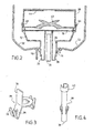
- the module comprises electrical conductors 28 and 30 between the connector 24 and the printed circuit 16 carrying the or light emitting diodes.
- Such conductors are shown in Figures 3 and 4, and are more particularly intended to ensure a central electrical contact in the axis of the cylindrical connector 24 and an electrical contact at the periphery of the connector 24.
- the conductor 28 may have tabs 32 for contact peripheral, these tabs 32 passing through openings 34 formed in the connector 24.
- the tabs 32 can be obtained by folding a tongue 34, the latter possibly being continue with a part 36 intended to come into contact with the printed circuit 16 and be connected, for example by soldering.
- the conductor 28 will advantageously be made in one material with a certain elasticity, so as to ensure good electrical contact between the lugs 32 and the electrical studs contained in the socket receiving the connector 24.
- the conductor 30 can be made in the form of a pawn cylindrical, and ensure a central electrical contact in the axis of the cylindrical connector 24.
- the conductor 30 is formed with a first end 38 in the center of the connector 24 ensuring electrical contact with a central electrical stud contained in the receiving socket the connector 24, and with a second end 40 intended to come into contact with the circuit printed 16 and be connected to it, for example by soldering.
- the conductors 28 and 30 are held in place in the connector 24 while being separated from each other, the connector being for example obtained by overmolding of the material insulator constituting the housing 12 and the connector 24 on the conductors 28 and 30.
- the transparent cover 20 includes means for deflecting the light rays emitted by the diode or diodes electroluminescent 14.
- Such deflection means can for example comprise a first element 42, located in the vicinity of the diode or diodes 14, and capable of distributing the light emitted by the one or more light-emitting diodes in an XY plane essentially perpendicular to the direction general emission X, essentially homogeneously on a second element 44, in general form of plate and able to straighten the light incident on it substantially towards the general direction of emission X'-X, depending on the lighting or signaling function concerned.
- a first element 42 located in the vicinity of the diode or diodes 14, and capable of distributing the light emitted by the one or more light-emitting diodes in an XY plane essentially perpendicular to the direction general emission X, essentially homogeneously on a second element 44, in general form of plate and able to straighten the light incident on it substantially towards the general direction of emission X'-X, depending on the lighting or signaling function concerned.
- Such deflection means are for example described in document FR-A-2 813 379, in the name of the Claimant.
- the cover 20 may by example include ribs 46, intended to cooperate with grooves 48 formed in the inner wall 18 of the housing 12.
- the module 10 is then ready to be used. As shown schematically in section in Figure 2, simply engage the connector 24 in the socket 50 provided in the lighting or signaling device to be fitted.
- This socket 50 was for example provided to receive the base of an incandescent lamp, cooperating with a reflector 52 for form a lighting or signaling beam.
- the module is fixed in the socket 50 by a rotation, so that the module 10 is mounted at bayonet in the socket 50.
- the connector 24 is thus used both for positioning the module in the lighting or signaling device, and its power supply.
- a module has therefore been produced according to the present invention which makes it possible to use in a lighting or signaling device a light-emitting diode in place of a incandescent source, without having to completely overhaul the architecture of the device lighting or signaling, and also making it possible to produce a lighting or signaling system comprising both incandescent sources and diodes electroluminescent, which has only one printed circuit to supply power of two types of light sources, the module itself comprising the printed circuit for the supply of the light-emitting diode (s) it contains.
Landscapes
- Engineering & Computer Science (AREA)
- General Engineering & Computer Science (AREA)
- Physics & Mathematics (AREA)
- Microelectronics & Electronic Packaging (AREA)
- Optics & Photonics (AREA)
- Fastening Of Light Sources Or Lamp Holders (AREA)
- Led Device Packages (AREA)
- Arrangement Of Elements, Cooling, Sealing, Or The Like Of Lighting Devices (AREA)
Abstract
Description
La présente invention concerne de manière générale les dispositifs d'éclairage ou de signalisation, dont les sources lumineuses sont à incandescence, et que l'on désire changer par des sources lumineuses du type de diodes électroluminescentes.The present invention relates generally to lighting or lighting devices. signaling, whose light sources are incandescent, and which one wishes to change by light sources of the light-emitting diode type.
Une telle situation peut par exemple se rencontrer dans les dispositifs d'éclairage ou de signalisation de véhicules automobiles, des tels dispositifs d'éclairage ou de signalisation comportant des sources lumineuses à incandescence seules ou associées à des sources constituées de diodes électroluminescentes.Such a situation can for example be encountered in lighting or lighting devices. signaling of motor vehicles, such lighting or signaling devices comprising incandescent light sources alone or associated with sources made up of light-emitting diodes.
Les diodes électroluminescentes ont de manière connue une durée de vie beaucoup plus élevée que celle des sources à incandescence. L'utilisation de diodes électroluminescentes permet de profiter de leur faible encombrement pour réaliser des dispositifs d'éclairage ou de signalisation relativement compacts. De plus, le faible dégagement de chaleur provoqué par le fonctionnement des diodes électroluminescentes permet par exemple d'utiliser dans leur environnement immédiat des matières plastiques, alors que des lampes à incandescence ou à halogènes imposeraient dans les mêmes conditions l'utilisation de matériaux pouvant supporter des températures élevées. Il en résulte donc un encombrement et un coût réduits.Light-emitting diodes have, in known manner, a long service life higher than that of incandescent sources. The use of diodes light-emitting allows to take advantage of their small footprint to achieve relatively compact lighting or signaling devices. In addition, the low heat generation caused by the operation of light emitting diodes allows for example to use in their immediate environment plastics, whereas incandescent or halogen lamps would impose under the same conditions the use of materials capable of withstanding high temperatures. This therefore results in a reduced size and cost.
On peut alors désirer remplacer des sources à incandescence par des diodes électroluminescentes, mais il est alors nécessaire de modifier profondément la structure du dispositif d'éclairage ou de signalisation pour pouvoir le faire. De plus, les dispositifs d'éclairage ou de signalisation doivent émettre, selon la fonction d'éclairage ou de signalisation dans laquelle la source à incandescence est utilisée, un faisceau lumineux dont la photométrie est définie réglementairement. Le simple remplacement d'une source à incandescence par une diode électroluminescente aura alors pour résultat que le faisceau lumineux n'aura plus la photométrie réglementaire.We may then wish to replace incandescent sources with diodes electroluminescent, but it is then necessary to profoundly modify the structure of the lighting or signaling device to be able to do so. In addition, the devices lighting or signaling must emit, depending on the lighting or signaling in which the incandescent source is used, a light beam whose photometry is defined by law. Simply replacing a source at incandescent by a light emitting diode will then result in the beam light will no longer have regulatory photometry.
Il est d'autres cas où le dispositif d'éclairage ou de signalisation comporte à la fois des sources à incandescence et des diodes électroluminescentes pour assurer différentes fonctions. Par construction, il est alors nécessaire de prévoir dans ce dispositif d'éclairage ou de signalisation, deux circuits imprimés différents, l'un pour les sources à incandescence, l'autre pour les diodes électroluminescentes, de manière à ce que les faisceaux lumineux émis par ces sources différentes soient réglementaires.There are other cases where the lighting or signaling device includes both incandescent sources and light emitting diodes to perform different functions. By construction, it is then necessary to provide in this lighting device or signaling, two different printed circuits, one for incandescent sources, the other for light-emitting diodes, so that the light beams emitted by these different sources are regulatory.
La présente invention se place dans ce contexte et elle a pour but de proposer un module permettant d'utiliser dans un dispositif d'éclairage ou de signalisation une diode électroluminescente à la place d'une source à incandescence, sans avoir à remanier complètement l'architecture du dispositif d'éclairage ou de signalisation, et permettant également de réaliser un dispositif d'éclairage ou de signalisation comportant à la fois des sources à incandescence et des diodes électroluminescentes, qui ne comporte qu'un seul circuit imprimé pour assurer l'alimentation de des deux types de sources lumineuses.The present invention is placed in this context and it aims to provide a module for using a diode in a lighting or signaling device electroluminescent instead of an incandescent source, without having to rearrange completely the architecture of the lighting or signaling device, and allowing also to produce a lighting or signaling device comprising both incandescent sources and light emitting diodes, which has only one printed circuit to supply the two types of light sources.
La présente invention a donc pour objet un module de positionnement et d'alimentation d'une diode électroluminescente, le module comportant un boítier formant support pour au moins une diode électroluminescente et un connecteur d'alimentation électrique.The present invention therefore relates to a positioning module and for supplying a light-emitting diode, the module comprising a housing forming support for at least one light-emitting diode and a power connector electric.
Selon la présente invention, le connecteur a la forme et les dimensions du culot d'une lampe à incandescence, le boítier et le connecteur étant d'une seule pièce, et la diode électroluminescente étant montée sur un circuit imprimé.According to the present invention, the connector has the shape and dimensions of the base of a incandescent lamp, the housing and the connector being in one piece, and the diode electroluminescent being mounted on a printed circuit.
Selon d'autres caractéristiques avantageuses et non limitatives de l'invention :
- le boítier comporte des butées de positionnement du circuit imprimé portant la diode électroluminescente.
- le boítier est fermé par un couvercle transparent permettant le passage des rayons lumineux émis par la diode électroluminescente selon une direction générale d'émission.
- le couvercle transparent est fixé sur le boítier par encliquetage.
- le couvercle comporte des moyens de déviation des rayons lumineux émis par la diode électroluminescente.
- les moyens de déviation des rayons lumineux émis par la diode électroluminescente comprennent un premier élément apte à répartir la lumière émise par la diode électroluminescente dans un plan essentiellement perpendiculaire à la direction générale d'émission, de façon essentiellement homogène sur un deuxième élément en forme générale de plaque et apte à redresser la lumière incidente sur lui sensiblement vers la direction générale d'émission.
- le module comporte des conducteurs électriques entre le connecteur et le circuit imprimé portant la diode électroluminescente.
- the housing includes stops for positioning the printed circuit carrying the light emitting diode.
- the housing is closed by a transparent cover allowing the passage of light rays emitted by the light emitting diode in a general direction of emission.
- the transparent cover is fixed on the housing by snap-fastening.
- the cover includes means for deflecting the light rays emitted by the light-emitting diode.
- the means for deflecting the light rays emitted by the light-emitting diode comprise a first element capable of distributing the light emitted by the light-emitting diode in a plane essentially perpendicular to the general direction of emission, essentially homogeneously over a second element in general form plate and able to straighten the light incident on it substantially towards the general direction of emission.
- the module comprises electrical conductors between the connector and the printed circuit carrying the light-emitting diode.
D'autres buts, caractéristiques et avantages de la présente invention ressortiront clairement de la description qui va maintenant être faite d'un exemple de réalisation donné à titre non limitatif en référence aux dessins annexés sur lesquels :
- La Figure 1 représente une vue éclatée d'un module selon la présente invention,
- La Figure 2 représente une vue en coupe du module de la Figure 1, et
- Les Figures 3A et 3B représentent des vues en perspective de conducteurs électriques équipant le module de la Figure 1.
- FIG. 1 represents an exploded view of a module according to the present invention,
- Figure 2 shows a sectional view of the module of Figure 1, and
- Figures 3A and 3B show perspective views of electrical conductors fitted to the module of Figure 1.
Sur les différentes Figures, les éléments identiques ou jouant le même rôle sont affectés des mêmes signes de référence.In the different Figures, identical elements or playing the same role are affected by the same reference signs.
On a représenté sur les Figures un module de positionnement et d'alimentation d'une
diode électroluminescente, ce module étant désigné dans son ensemble par la référence 10. Le
module comporte un boítier 12 formant support pour au moins une diode électroluminescente
14, deux telles diodes ayant été représentées sur la Figure 1. Les diodes 14 sont montées sur
un circuit imprimé 16, dont le pourtour extérieur est complémentaire de la forme de la paroi
intérieure 18 du boítier 12.The figures show a module for positioning and supplying a
light emitting diode, this module being designated as a whole by the
Le boítier 12 est fermé par un couvercle 20, réalisé en un matériau transparent de
manière à permettre le passage des rayons lumineux émis par la diode électroluminescente 14
selon une direction générale d'émission X.The
De manière à assurer le positionnement de la ou des diodes 14, le boítier comporte des
butées 22 sur lesquelles vient en butée le circuit imprimé portant les diodes 14. Les butées 22
peuvent par exemple être obtenues par des épaulements 22 formés sur la paroi intérieure 18 du
boítier 12. In order to ensure the positioning of the diode or
Le boítier 12 comporte également un connecteur d'alimentation électrique 24. De
manière avantageuse, le boítier 12 et le connecteur 24 sont d'une seule pièce, et obtenus par
exemple par moulage par injection d'une matière thermoplastique.The
Conformément à la présente invention, le connecteur 24 a la forme et les dimensions
du culot d'une lampe à incandescence. Dans le mode de réalisation représenté sur la Figure 1,
le connecteur 24 est cylindrique, et comporte des excroissances 26 permettant son montage à
baïonnette dans une douille conventionnelle, destinée à recevoir le culot d'une lampe à
incandescence.According to the present invention, the
De manière à assurer l'alimentation électrique de la ou des diodes, le module comporte
des conducteurs électriques 28 et 30 entre le connecteur 24 et le circuit imprimé 16 portant la
ou les diodes électroluminescentes. De tels conducteurs sont représentés sur les Figures 3 et 4,
et sont plus particulièrement destinés à assurer un contact électrique central dans l'axe du
connecteur cylindrique 24 et un contact électrique à la périphérie du connecteur 24.In order to ensure the electrical supply of the diode (s), the module comprises
Par exemple, le conducteur 28 peut comporter des pattes 32 pour un contact
périphérique, ces pattes 32 passant par des ouvertures 34 formées dans le connecteur 24. Les
pattes 32 peuvent être obtenues par pliage d'une languette 34, cette dernière pouvant se
continuer par une partie 36 destinée à venir au contact du circuit imprimé 16 et lui être
connectée, par exemple par soudure. Le conducteur 28 sera avantageusement réalisé en un
matériau présentant une certaine élasticité, de manière à assurer un bon contact électrique
entre les pattes 32 et les plots électriques contenus dans la douille recevant le connecteur 24.For example, the
De la même manière, le conducteur 30 pourra être réalisé sous la forme d'un pion
cylindrique, et assurer un contact électrique central dans l'axe du connecteur cylindrique 24.
Le conducteur 30 est formé avec une première extrémité 38 au centre du connecteur 24
assurant le contact électrique avec un plot électrique central contenu dans la douille recevant
le connecteur 24, et avec une seconde extrémité 40 destinée à venir au contact du circuit
imprimé 16 et lui être connectée, par exemple par soudure. In the same way, the
Les conducteurs 28 et 30 sont maintenus en place dans le connecteur 24 en étant
séparés l'un de l'autre, le connecteur étant par exemple obtenu par surmoulage du matériau
isolant constituant le boítier 12 et le connecteur 24 sur les conducteurs 28 et 30.The
Pour obtenir le faisceau lumineux ayant la photométrie requise par la fonction
d'éclairage ou de signalisation dont la ou les diodes électroluminescentes 14 sont la ou les
sources lumineuses, on pourra avantageusement prévoir que le couvercle transparent 20
comporte des moyens de déviation des rayons lumineux émis par la ou les diodes
électroluminescentes 14.To obtain the light beam with the photometry required by the function
lighting or signaling device, the light-emitting diode or
De tels moyens de déviation peuvent par exemple comporter un premier élément 42,
situé au voisinage de la ou des diodes 14, et apte à répartir la lumière émise par la ou les
diodes électroluminescentes dans un plan XY essentiellement perpendiculaire à la direction
générale d'émission X, de façon essentiellement homogène sur un deuxième élément 44, en
forme générale de plaque et apte à redresser la lumière incidente sur lui sensiblement vers la
direction générale d'émission X'-X, selon la fonction d'éclairage ou de signalisation
concernée.Such deflection means can for example comprise a
De tels moyens de déviation sont par exemple décrits dans le document FR-A-2 813 379, au nom de la Demanderesse.Such deflection means are for example described in document FR-A-2 813 379, in the name of the Claimant.
Pour faciliter le montage du couvercle 20 sur le boítier 12, on pourra prévoir que le
couvercle transparent soit fixé sur le boítier par encliquetage. Le couvercle 20 pourra par
exemple comporter des nervures 46, destinées à coopérer avec des sillons 48 formés dans la
paroi intérieure 18 du boítier 12.To facilitate mounting of the
Pour assembler le module de la présente invention, il suffit de disposer le circuit
imprimé 16 sur les butées 22, puis de souder les conducteurs 28 et 30 sur ce circuit imprimé.
Le couvercle 20 peut alors être fixé, par encliquetage, sur le boítier 12.To assemble the module of the present invention, it suffices to arrange the circuit
printed 16 on the
Le module 10 est alors prêt à être utilisé. Comme on l'a représenté schématiquement
en coupe sur la Figure 2, il suffit d'engager le connecteur 24 dans la douille 50 prévue dans le
dispositif d'éclairage ou de signalisation à équiper. Cette douille 50 était par exemple prévue
pour recevoir le culot d'une lampe à incandescence, coopérant avec un réflecteur 52 pour
former un faisceau d'éclairage ou de signalisation. De la même manière que pour cette lampe,
on fixe le module dans la douille 50 par une rotation, de sorte que le module 10 est monté à
baïonnette dans la douille 50. Le connecteur 24 sert ainsi à la fois au positionnement du
module dans le dispositif d'éclairage ou de signalisation, et à son alimentation électrique.The
On a donc bien réalisé selon la présente invention un module permettant d'utiliser dans un dispositif d'éclairage ou de signalisation une diode électroluminescente à la place d'une source à incandescence, sans avoir à remanier complètement l'architecture du dispositif d'éclairage ou de signalisation, et permettant également de réaliser un dispositif d'éclairage ou de signalisation comportant à la fois des sources à incandescence et des diodes électroluminescentes, qui ne comporte qu'un seul circuit imprimé pour assurer l'alimentation de des deux types de sources lumineuses, le module comportant lui-même le circuit imprimé pour l'alimentation de la ou des diodes électroluminescentes qu'il contient.A module has therefore been produced according to the present invention which makes it possible to use in a lighting or signaling device a light-emitting diode in place of a incandescent source, without having to completely overhaul the architecture of the device lighting or signaling, and also making it possible to produce a lighting or signaling system comprising both incandescent sources and diodes electroluminescent, which has only one printed circuit to supply power of two types of light sources, the module itself comprising the printed circuit for the supply of the light-emitting diode (s) it contains.
Bien entendu, la présente invention n'est pas limitée aux modes de réalisation qui ont été décrits, mais l'homme du métier pourra au contraire lui apporter de nombreuses modifications qui rentrent dans son cadre. C'est ainsi par exemple qu'on pourra prévoir un montage du module par vissage, au lieu du montage à baïonnette qui a été décrit.Of course, the present invention is not limited to the embodiments which have have been described, but those skilled in the art may on the contrary provide it with numerous modifications that fall within its scope. This is how, for example, we can plan a mounting of the module by screwing, instead of the bayonet mounting which has been described.
Claims (7)
Applications Claiming Priority (2)
| Application Number | Priority Date | Filing Date | Title |
|---|---|---|---|
| FR0211346 | 2002-09-12 | ||
| FR0211346A FR2844579B1 (en) | 2002-09-12 | 2002-09-12 | MODULE FOR POSITIONING AND SUPPLYING LIGHT EMITTING DIODE |
Publications (2)
| Publication Number | Publication Date |
|---|---|
| EP1398563A1 true EP1398563A1 (en) | 2004-03-17 |
| EP1398563B1 EP1398563B1 (en) | 2006-02-22 |
Family
ID=31726043
Family Applications (1)
| Application Number | Title | Priority Date | Filing Date |
|---|---|---|---|
| EP03292243A Expired - Lifetime EP1398563B1 (en) | 2002-09-12 | 2003-09-11 | Power supply and mounting module for light-emitting diode |
Country Status (4)
| Country | Link |
|---|---|
| EP (1) | EP1398563B1 (en) |
| AT (1) | ATE318390T1 (en) |
| DE (1) | DE60303655T2 (en) |
| FR (1) | FR2844579B1 (en) |
Cited By (3)
| Publication number | Priority date | Publication date | Assignee | Title |
|---|---|---|---|---|
| WO2007036193A1 (en) * | 2005-09-30 | 2007-04-05 | Osram Opto Semiconductors Gmbh | Radiation-emitting element and method for producing a radiation-emitting element |
| WO2009053887A2 (en) * | 2007-10-26 | 2009-04-30 | Koninklijke Philips Electronics N.V. | Illumination system |
| EP2275736A2 (en) * | 2009-07-17 | 2011-01-19 | Steinel GmbH | Light module unit |
Families Citing this family (2)
| Publication number | Priority date | Publication date | Assignee | Title |
|---|---|---|---|---|
| DE102009055858A1 (en) * | 2009-11-26 | 2011-06-01 | Osram Gesellschaft mit beschränkter Haftung | Lighting device and method for building a lighting device |
| US11744026B1 (en) | 2022-08-03 | 2023-08-29 | Appleton Grp Llc | Chassis housing and support structures to secure a circuit board within the chassis housing |
Citations (6)
| Publication number | Priority date | Publication date | Assignee | Title |
|---|---|---|---|---|
| US5947588A (en) * | 1997-10-06 | 1999-09-07 | Grand General Accessories Manufacturing Inc. | Light fixture with an LED light bulb having a conventional connection post |
| DE29915140U1 (en) * | 1999-08-29 | 1999-11-25 | Strobl, Thomas, 82541 Münsing | LED spotlight |
| DE20014813U1 (en) * | 2000-08-26 | 2000-12-14 | Müller, Stefan, 83278 Traunstein | Compact, multi-beam LED light set |
| US6276822B1 (en) * | 1998-02-20 | 2001-08-21 | Yerchanik Bedrosian | Method of replacing a conventional vehicle light bulb with a light-emitting diode array |
| FR2813379A1 (en) | 2000-08-28 | 2002-03-01 | Valeo Vision | SIGNAL LIGHT WITH SIMPLIFIED OPTICAL STRUCTURE |
| US6357902B1 (en) * | 2000-09-25 | 2002-03-19 | Brian Horowitz | After market LED taillight bulb |
-
2002
- 2002-09-12 FR FR0211346A patent/FR2844579B1/en not_active Expired - Fee Related
-
2003
- 2003-09-11 AT AT03292243T patent/ATE318390T1/en not_active IP Right Cessation
- 2003-09-11 DE DE60303655T patent/DE60303655T2/en not_active Expired - Lifetime
- 2003-09-11 EP EP03292243A patent/EP1398563B1/en not_active Expired - Lifetime
Patent Citations (6)
| Publication number | Priority date | Publication date | Assignee | Title |
|---|---|---|---|---|
| US5947588A (en) * | 1997-10-06 | 1999-09-07 | Grand General Accessories Manufacturing Inc. | Light fixture with an LED light bulb having a conventional connection post |
| US6276822B1 (en) * | 1998-02-20 | 2001-08-21 | Yerchanik Bedrosian | Method of replacing a conventional vehicle light bulb with a light-emitting diode array |
| DE29915140U1 (en) * | 1999-08-29 | 1999-11-25 | Strobl, Thomas, 82541 Münsing | LED spotlight |
| DE20014813U1 (en) * | 2000-08-26 | 2000-12-14 | Müller, Stefan, 83278 Traunstein | Compact, multi-beam LED light set |
| FR2813379A1 (en) | 2000-08-28 | 2002-03-01 | Valeo Vision | SIGNAL LIGHT WITH SIMPLIFIED OPTICAL STRUCTURE |
| US6357902B1 (en) * | 2000-09-25 | 2002-03-19 | Brian Horowitz | After market LED taillight bulb |
Cited By (5)
| Publication number | Priority date | Publication date | Assignee | Title |
|---|---|---|---|---|
| WO2007036193A1 (en) * | 2005-09-30 | 2007-04-05 | Osram Opto Semiconductors Gmbh | Radiation-emitting element and method for producing a radiation-emitting element |
| WO2009053887A2 (en) * | 2007-10-26 | 2009-04-30 | Koninklijke Philips Electronics N.V. | Illumination system |
| WO2009053887A3 (en) * | 2007-10-26 | 2009-06-11 | Koninkl Philips Electronics Nv | Illumination system |
| EP2275736A2 (en) * | 2009-07-17 | 2011-01-19 | Steinel GmbH | Light module unit |
| EP2275736A3 (en) * | 2009-07-17 | 2012-08-01 | Steinel GmbH | Light module unit |
Also Published As
| Publication number | Publication date |
|---|---|
| FR2844579B1 (en) | 2005-05-27 |
| FR2844579A1 (en) | 2004-03-19 |
| DE60303655D1 (en) | 2006-04-27 |
| DE60303655T2 (en) | 2006-12-14 |
| EP1398563B1 (en) | 2006-02-22 |
| ATE318390T1 (en) | 2006-03-15 |
Similar Documents
| Publication | Publication Date | Title |
|---|---|---|
| CN102182971B (en) | A light source unit for a semiconductor-type light source of vehicle lighting device and a vehicle lighting device | |
| JP4395104B2 (en) | Lighting device | |
| EP1570205B1 (en) | Mobile illuminating device comprising a tubular housing | |
| US5384693A (en) | Tail light for a bicycle | |
| JP5621489B2 (en) | Light source unit of semiconductor light source for vehicle lamp, vehicle lamp | |
| EP1727170B1 (en) | Electric device comprising a cover plate with an illuminating function | |
| JP2005056708A (en) | Lighting apparatus | |
| FR2922167A1 (en) | LIGHTING MODULE FOR A HEADLIGHT OR LIGHTING OF A MOTOR VEHICLE. | |
| FR2870081A1 (en) | LIGHTING DEVICE WITH MODE CHANGE SWITCH | |
| EP3104074A1 (en) | Positioning device of a led support on a support element and illumination or signalisation device comprising such a device | |
| FR3015002A1 (en) | LIGHTING DEVICE | |
| EP1516777B1 (en) | Illuminating device for electric cigar lighter or multi-functional electrical socket. | |
| EP1398563B1 (en) | Power supply and mounting module for light-emitting diode | |
| FR2887393A1 (en) | Light source module for vehicle lamp, has hemispherical cover formed of glass fixed on the non-conductive layer of circuit board, by melting the low-melting glass arranged between the cover and non-conductive layer | |
| JP5407025B2 (en) | Light source unit of semiconductor light source for vehicle lamp, vehicle lamp | |
| CN1908507A (en) | Electric torch | |
| FR2899164A1 (en) | LIGHTING DEVICE FOR CIGAR LIGHTER OR ELECTRIC MULTI-FUNCTION SOCKET | |
| EP1030998A1 (en) | Motor vehicle headlight equipped with a lamp and improved electromagnetic shielding means | |
| FR2710131A1 (en) | Connector and high-voltage generator assembly for a motor vehicle discharge lamp | |
| FR2894324A1 (en) | Light, especially for navigation, has series of LED circuits fitted between upper and lower electrical assembly units | |
| EP1590602A1 (en) | Illumination device | |
| WO2023031072A1 (en) | Light-emitting module comprising a mount intended to dissipate heat | |
| EP1111297B1 (en) | Support for a self powered emergency lighting unit and self powered unit comprising such a support | |
| JP2004362975A (en) | Electronic apparatus | |
| FR2711864A1 (en) | Electric current switch with touch-sensitive control |
Legal Events
| Date | Code | Title | Description |
|---|---|---|---|
| PUAI | Public reference made under article 153(3) epc to a published international application that has entered the european phase |
Free format text: ORIGINAL CODE: 0009012 |
|
| AK | Designated contracting states |
Kind code of ref document: A1 Designated state(s): AT BE BG CH CY CZ DE DK EE ES FI FR GB GR HU IE IT LI LU MC NL PT RO SE SI SK TR |
|
| AX | Request for extension of the european patent |
Extension state: AL LT LV MK |
|
| 17P | Request for examination filed |
Effective date: 20040621 |
|
| 17Q | First examination report despatched |
Effective date: 20040810 |
|
| AKX | Designation fees paid |
Designated state(s): AT BE BG CH CY CZ DE DK EE ES FI FR GB GR HU IE IT LI LU MC NL PT RO SE SI SK TR |
|
| RAP1 | Party data changed (applicant data changed or rights of an application transferred) |
Owner name: VIGNAL SYSTEMS |
|
| GRAP | Despatch of communication of intention to grant a patent |
Free format text: ORIGINAL CODE: EPIDOSNIGR1 |
|
| GRAS | Grant fee paid |
Free format text: ORIGINAL CODE: EPIDOSNIGR3 |
|
| GRAA | (expected) grant |
Free format text: ORIGINAL CODE: 0009210 |
|
| AK | Designated contracting states |
Kind code of ref document: B1 Designated state(s): AT BE BG CH CY CZ DE DK EE ES FI FR GB GR HU IE IT LI LU MC NL PT RO SE SI SK TR |
|
| PG25 | Lapsed in a contracting state [announced via postgrant information from national office to epo] |
Ref country code: IT Free format text: LAPSE BECAUSE OF FAILURE TO SUBMIT A TRANSLATION OF THE DESCRIPTION OR TO PAY THE FEE WITHIN THE PRESCRIBED TIME-LIMIT;WARNING: LAPSES OF ITALIAN PATENTS WITH EFFECTIVE DATE BEFORE 2007 MAY HAVE OCCURRED AT ANY TIME BEFORE 2007. THE CORRECT EFFECTIVE DATE MAY BE DIFFERENT FROM THE ONE RECORDED. Effective date: 20060222 Ref country code: IE Free format text: LAPSE BECAUSE OF FAILURE TO SUBMIT A TRANSLATION OF THE DESCRIPTION OR TO PAY THE FEE WITHIN THE PRESCRIBED TIME-LIMIT Effective date: 20060222 Ref country code: RO Free format text: LAPSE BECAUSE OF FAILURE TO SUBMIT A TRANSLATION OF THE DESCRIPTION OR TO PAY THE FEE WITHIN THE PRESCRIBED TIME-LIMIT Effective date: 20060222 Ref country code: SI Free format text: LAPSE BECAUSE OF FAILURE TO SUBMIT A TRANSLATION OF THE DESCRIPTION OR TO PAY THE FEE WITHIN THE PRESCRIBED TIME-LIMIT Effective date: 20060222 Ref country code: SK Free format text: LAPSE BECAUSE OF FAILURE TO SUBMIT A TRANSLATION OF THE DESCRIPTION OR TO PAY THE FEE WITHIN THE PRESCRIBED TIME-LIMIT Effective date: 20060222 Ref country code: GB Free format text: LAPSE BECAUSE OF FAILURE TO SUBMIT A TRANSLATION OF THE DESCRIPTION OR TO PAY THE FEE WITHIN THE PRESCRIBED TIME-LIMIT Effective date: 20060222 Ref country code: FI Free format text: LAPSE BECAUSE OF FAILURE TO SUBMIT A TRANSLATION OF THE DESCRIPTION OR TO PAY THE FEE WITHIN THE PRESCRIBED TIME-LIMIT Effective date: 20060222 Ref country code: AT Free format text: LAPSE BECAUSE OF FAILURE TO SUBMIT A TRANSLATION OF THE DESCRIPTION OR TO PAY THE FEE WITHIN THE PRESCRIBED TIME-LIMIT Effective date: 20060222 Ref country code: NL Free format text: LAPSE BECAUSE OF FAILURE TO SUBMIT A TRANSLATION OF THE DESCRIPTION OR TO PAY THE FEE WITHIN THE PRESCRIBED TIME-LIMIT Effective date: 20060222 |
|
| REG | Reference to a national code |
Ref country code: GB Ref legal event code: FG4D Free format text: NOT ENGLISH |
|
| REG | Reference to a national code |
Ref country code: CH Ref legal event code: EP |
|
| REG | Reference to a national code |
Ref country code: IE Ref legal event code: FG4D Free format text: LANGUAGE OF EP DOCUMENT: FRENCH |
|
| REF | Corresponds to: |
Ref document number: 60303655 Country of ref document: DE Date of ref document: 20060427 Kind code of ref document: P |
|
| PG25 | Lapsed in a contracting state [announced via postgrant information from national office to epo] |
Ref country code: DK Free format text: LAPSE BECAUSE OF FAILURE TO SUBMIT A TRANSLATION OF THE DESCRIPTION OR TO PAY THE FEE WITHIN THE PRESCRIBED TIME-LIMIT Effective date: 20060522 Ref country code: SE Free format text: LAPSE BECAUSE OF FAILURE TO SUBMIT A TRANSLATION OF THE DESCRIPTION OR TO PAY THE FEE WITHIN THE PRESCRIBED TIME-LIMIT Effective date: 20060522 Ref country code: BG Free format text: LAPSE BECAUSE OF FAILURE TO SUBMIT A TRANSLATION OF THE DESCRIPTION OR TO PAY THE FEE WITHIN THE PRESCRIBED TIME-LIMIT Effective date: 20060522 |
|
| PG25 | Lapsed in a contracting state [announced via postgrant information from national office to epo] |
Ref country code: ES Free format text: LAPSE BECAUSE OF FAILURE TO SUBMIT A TRANSLATION OF THE DESCRIPTION OR TO PAY THE FEE WITHIN THE PRESCRIBED TIME-LIMIT Effective date: 20060602 |
|
| PG25 | Lapsed in a contracting state [announced via postgrant information from national office to epo] |
Ref country code: PT Free format text: LAPSE BECAUSE OF FAILURE TO SUBMIT A TRANSLATION OF THE DESCRIPTION OR TO PAY THE FEE WITHIN THE PRESCRIBED TIME-LIMIT Effective date: 20060724 |
|
| NLV1 | Nl: lapsed or annulled due to failure to fulfill the requirements of art. 29p and 29m of the patents act | ||
| GBV | Gb: ep patent (uk) treated as always having been void in accordance with gb section 77(7)/1977 [no translation filed] |
Effective date: 20060222 |
|
| REG | Reference to a national code |
Ref country code: IE Ref legal event code: FD4D |
|
| PG25 | Lapsed in a contracting state [announced via postgrant information from national office to epo] |
Ref country code: BE Free format text: LAPSE BECAUSE OF NON-PAYMENT OF DUE FEES Effective date: 20060930 Ref country code: MC Free format text: LAPSE BECAUSE OF NON-PAYMENT OF DUE FEES Effective date: 20060930 |
|
| PLBE | No opposition filed within time limit |
Free format text: ORIGINAL CODE: 0009261 |
|
| STAA | Information on the status of an ep patent application or granted ep patent |
Free format text: STATUS: NO OPPOSITION FILED WITHIN TIME LIMIT |
|
| 26N | No opposition filed |
Effective date: 20061123 |
|
| BERE | Be: lapsed |
Owner name: VIGNAL SYSTEMS Effective date: 20060930 |
|
| PG25 | Lapsed in a contracting state [announced via postgrant information from national office to epo] |
Ref country code: GR Free format text: LAPSE BECAUSE OF FAILURE TO SUBMIT A TRANSLATION OF THE DESCRIPTION OR TO PAY THE FEE WITHIN THE PRESCRIBED TIME-LIMIT Effective date: 20060523 Ref country code: CZ Free format text: LAPSE BECAUSE OF FAILURE TO SUBMIT A TRANSLATION OF THE DESCRIPTION OR TO PAY THE FEE WITHIN THE PRESCRIBED TIME-LIMIT Effective date: 20060222 |
|
| REG | Reference to a national code |
Ref country code: CH Ref legal event code: PL |
|
| PG25 | Lapsed in a contracting state [announced via postgrant information from national office to epo] |
Ref country code: EE Free format text: LAPSE BECAUSE OF FAILURE TO SUBMIT A TRANSLATION OF THE DESCRIPTION OR TO PAY THE FEE WITHIN THE PRESCRIBED TIME-LIMIT Effective date: 20060222 |
|
| PG25 | Lapsed in a contracting state [announced via postgrant information from national office to epo] |
Ref country code: TR Free format text: LAPSE BECAUSE OF FAILURE TO SUBMIT A TRANSLATION OF THE DESCRIPTION OR TO PAY THE FEE WITHIN THE PRESCRIBED TIME-LIMIT Effective date: 20060222 Ref country code: LU Free format text: LAPSE BECAUSE OF NON-PAYMENT OF DUE FEES Effective date: 20060911 Ref country code: HU Free format text: LAPSE BECAUSE OF FAILURE TO SUBMIT A TRANSLATION OF THE DESCRIPTION OR TO PAY THE FEE WITHIN THE PRESCRIBED TIME-LIMIT Effective date: 20060823 Ref country code: CH Free format text: LAPSE BECAUSE OF NON-PAYMENT OF DUE FEES Effective date: 20070930 Ref country code: LI Free format text: LAPSE BECAUSE OF NON-PAYMENT OF DUE FEES Effective date: 20070930 |
|
| PG25 | Lapsed in a contracting state [announced via postgrant information from national office to epo] |
Ref country code: CY Free format text: LAPSE BECAUSE OF FAILURE TO SUBMIT A TRANSLATION OF THE DESCRIPTION OR TO PAY THE FEE WITHIN THE PRESCRIBED TIME-LIMIT Effective date: 20060222 |
|
| REG | Reference to a national code |
Ref country code: FR Ref legal event code: PLFP Year of fee payment: 14 |
|
| PGFP | Annual fee paid to national office [announced via postgrant information from national office to epo] |
Ref country code: DE Payment date: 20160727 Year of fee payment: 14 |
|
| PGFP | Annual fee paid to national office [announced via postgrant information from national office to epo] |
Ref country code: FR Payment date: 20160721 Year of fee payment: 14 |
|
| REG | Reference to a national code |
Ref country code: DE Ref legal event code: R119 Ref document number: 60303655 Country of ref document: DE |
|
| REG | Reference to a national code |
Ref country code: FR Ref legal event code: ST Effective date: 20180531 |
|
| PG25 | Lapsed in a contracting state [announced via postgrant information from national office to epo] |
Ref country code: DE Free format text: LAPSE BECAUSE OF NON-PAYMENT OF DUE FEES Effective date: 20180404 |
|
| PG25 | Lapsed in a contracting state [announced via postgrant information from national office to epo] |
Ref country code: FR Free format text: LAPSE BECAUSE OF NON-PAYMENT OF DUE FEES Effective date: 20171002 |