EP1398558B1 - Pipe nipple and method of manufacturing the same - Google Patents
Pipe nipple and method of manufacturing the same Download PDFInfo
- Publication number
- EP1398558B1 EP1398558B1 EP20030019139 EP03019139A EP1398558B1 EP 1398558 B1 EP1398558 B1 EP 1398558B1 EP 20030019139 EP20030019139 EP 20030019139 EP 03019139 A EP03019139 A EP 03019139A EP 1398558 B1 EP1398558 B1 EP 1398558B1
- Authority
- EP
- European Patent Office
- Prior art keywords
- nipple
- hose
- bore
- pipe
- formation
- Prior art date
- Legal status (The legal status is an assumption and is not a legal conclusion. Google has not performed a legal analysis and makes no representation as to the accuracy of the status listed.)
- Expired - Lifetime
Links
- 210000002445 nipple Anatomy 0.000 title claims description 108
- 238000004519 manufacturing process Methods 0.000 title claims description 4
- 238000001816 cooling Methods 0.000 claims description 20
- 230000015572 biosynthetic process Effects 0.000 claims description 11
- 238000000034 method Methods 0.000 claims description 11
- 238000007493 shaping process Methods 0.000 claims 2
- 239000012530 fluid Substances 0.000 description 11
- 238000005520 cutting process Methods 0.000 description 5
- 238000005755 formation reaction Methods 0.000 description 5
- 239000002184 metal Substances 0.000 description 4
- 229910052751 metal Inorganic materials 0.000 description 4
- 230000007704 transition Effects 0.000 description 4
- XLYOFNOQVPJJNP-UHFFFAOYSA-N water Substances O XLYOFNOQVPJJNP-UHFFFAOYSA-N 0.000 description 4
- 239000002826 coolant Substances 0.000 description 3
- 238000003754 machining Methods 0.000 description 3
- 230000013011 mating Effects 0.000 description 2
- 230000000007 visual effect Effects 0.000 description 2
- 229910000831 Steel Inorganic materials 0.000 description 1
- 238000009825 accumulation Methods 0.000 description 1
- 230000002411 adverse Effects 0.000 description 1
- 238000013459 approach Methods 0.000 description 1
- 238000010276 construction Methods 0.000 description 1
- 238000005260 corrosion Methods 0.000 description 1
- 230000007797 corrosion Effects 0.000 description 1
- 230000001419 dependent effect Effects 0.000 description 1
- 150000002739 metals Chemical class 0.000 description 1
- 239000010959 steel Substances 0.000 description 1
Images

Classifications
-
- B—PERFORMING OPERATIONS; TRANSPORTING
- B23—MACHINE TOOLS; METAL-WORKING NOT OTHERWISE PROVIDED FOR
- B23P—METAL-WORKING NOT OTHERWISE PROVIDED FOR; COMBINED OPERATIONS; UNIVERSAL MACHINE TOOLS
- B23P13/00—Making metal objects by operations essentially involving machining but not covered by a single other subclass
-
- F—MECHANICAL ENGINEERING; LIGHTING; HEATING; WEAPONS; BLASTING
- F16—ENGINEERING ELEMENTS AND UNITS; GENERAL MEASURES FOR PRODUCING AND MAINTAINING EFFECTIVE FUNCTIONING OF MACHINES OR INSTALLATIONS; THERMAL INSULATION IN GENERAL
- F16L—PIPES; JOINTS OR FITTINGS FOR PIPES; SUPPORTS FOR PIPES, CABLES OR PROTECTIVE TUBING; MEANS FOR THERMAL INSULATION IN GENERAL
- F16L33/00—Arrangements for connecting hoses to rigid members; Rigid hose connectors, i.e. single members engaging both hoses
- F16L33/22—Arrangements for connecting hoses to rigid members; Rigid hose connectors, i.e. single members engaging both hoses with means not mentioned in the preceding groups for gripping the hose between inner and outer parts
- F16L33/227—Arrangements for connecting hoses to rigid members; Rigid hose connectors, i.e. single members engaging both hoses with means not mentioned in the preceding groups for gripping the hose between inner and outer parts the hose being introduced into or onto the connecting member and automatically locked
-
- F—MECHANICAL ENGINEERING; LIGHTING; HEATING; WEAPONS; BLASTING
- F01—MACHINES OR ENGINES IN GENERAL; ENGINE PLANTS IN GENERAL; STEAM ENGINES
- F01P—COOLING OF MACHINES OR ENGINES IN GENERAL; COOLING OF INTERNAL-COMBUSTION ENGINES
- F01P11/00—Component parts, details, or accessories not provided for in, or of interest apart from, groups F01P1/00 - F01P9/00
- F01P11/04—Arrangements of liquid pipes or hoses
-
- F—MECHANICAL ENGINEERING; LIGHTING; HEATING; WEAPONS; BLASTING
- F16—ENGINEERING ELEMENTS AND UNITS; GENERAL MEASURES FOR PRODUCING AND MAINTAINING EFFECTIVE FUNCTIONING OF MACHINES OR INSTALLATIONS; THERMAL INSULATION IN GENERAL
- F16L—PIPES; JOINTS OR FITTINGS FOR PIPES; SUPPORTS FOR PIPES, CABLES OR PROTECTIVE TUBING; MEANS FOR THERMAL INSULATION IN GENERAL
- F16L33/00—Arrangements for connecting hoses to rigid members; Rigid hose connectors, i.e. single members engaging both hoses
- F16L33/20—Undivided rings, sleeves or like members contracted on the hose or expanded in the hose by means of tools; Arrangements using such members
-
- F—MECHANICAL ENGINEERING; LIGHTING; HEATING; WEAPONS; BLASTING
- F16—ENGINEERING ELEMENTS AND UNITS; GENERAL MEASURES FOR PRODUCING AND MAINTAINING EFFECTIVE FUNCTIONING OF MACHINES OR INSTALLATIONS; THERMAL INSULATION IN GENERAL
- F16L—PIPES; JOINTS OR FITTINGS FOR PIPES; SUPPORTS FOR PIPES, CABLES OR PROTECTIVE TUBING; MEANS FOR THERMAL INSULATION IN GENERAL
- F16L33/00—Arrangements for connecting hoses to rigid members; Rigid hose connectors, i.e. single members engaging both hoses
- F16L33/30—Arrangements for connecting hoses to rigid members; Rigid hose connectors, i.e. single members engaging both hoses comprising parts inside the hoses only
-
- F—MECHANICAL ENGINEERING; LIGHTING; HEATING; WEAPONS; BLASTING
- F16—ENGINEERING ELEMENTS AND UNITS; GENERAL MEASURES FOR PRODUCING AND MAINTAINING EFFECTIVE FUNCTIONING OF MACHINES OR INSTALLATIONS; THERMAL INSULATION IN GENERAL
- F16L—PIPES; JOINTS OR FITTINGS FOR PIPES; SUPPORTS FOR PIPES, CABLES OR PROTECTIVE TUBING; MEANS FOR THERMAL INSULATION IN GENERAL
- F16L37/00—Couplings of the quick-acting type
- F16L37/02—Couplings of the quick-acting type in which the connection is maintained only by friction of the parts being joined
- F16L37/04—Couplings of the quick-acting type in which the connection is maintained only by friction of the parts being joined with an elastic outer part pressing against an inner part by reason of its elasticity
-
- Y—GENERAL TAGGING OF NEW TECHNOLOGICAL DEVELOPMENTS; GENERAL TAGGING OF CROSS-SECTIONAL TECHNOLOGIES SPANNING OVER SEVERAL SECTIONS OF THE IPC; TECHNICAL SUBJECTS COVERED BY FORMER USPC CROSS-REFERENCE ART COLLECTIONS [XRACs] AND DIGESTS
- Y10—TECHNICAL SUBJECTS COVERED BY FORMER USPC
- Y10T—TECHNICAL SUBJECTS COVERED BY FORMER US CLASSIFICATION
- Y10T137/00—Fluid handling
- Y10T137/7287—Liquid level responsive or maintaining systems
- Y10T137/7297—With second diverse control
- Y10T137/73—Manual control
Definitions
- the present invention relates generally to pipe nipples, and, more particularly, the present invention relates to pipe nipples used as transition pieces between hoses and other system components in automobile cooling systems.
- the present invention relates to a method according to claim 1.
- the present invention relates to a nipple according to the preamble of claim 7.
- a nipple of this kind is known from US 5,487,571 .
- Pipe nipples are commonly used as transition pieces in fluid systems of all types.
- a pipe nipple is a short piece of pipe with each of the ends adapted for connection to other components or other pipes within the fluid system.
- pipe nipples in automobile cooling systems as a transition piece between cooling system components such as, for example, a water pump, and a hose conducting coolant to or from the pump.
- One end of the nipple has external threads thereon for threaded engagement with a threaded port on the pump, and the other end of the pipe nipple is adapted to receive thereon a prepared end of the hose.
- a ring clamp is used to secure the hose on the nipple.
- a portion of the nipple between the threads and the opposite end of the nipple is provided for engagement by a tool used to turn the nipple threads into the threads of the pump threaded port.
- the portion of the nipple engaged by the tool may be round or may have flattened faces, depending on the type of tool to be used for rotating the nipple.
- Known nipples of this type have been manufactured by machining processes.
- Known automotive cooling system nipples have disadvantages and inadequacies. Manufacturing a cooling system nipple by screw machining or other similar cutting equipment inherently leaves grooves on all surfaces that are touched by the machine tool. Such grooves on the interior surface of the pipe nipple bore are problematic to some degree. A rough surface along which the coolant flows increases the friction co-efficient in the pipe nipple, which then tends to inhibit the flow of coolant through the nipple. Moreover, a rough surface promotes the accumulation of corrosive products, which not only may adversely affect the strength of the connector, but also further inhibit flow through the pipe nipple.
- nipples On relatively short nipples, as commonly found in automotive cooling systems, the external surface provided for driving or rotating the nipple is small. Thus, it is difficult to engage the nipple with the proper drive tool, and positioning the tool off the drive surface can damage the threads on one end of the nipple or damage the mating surface for the hose on the other end of the nipple. If driven with a common wrench, it is necessary to rotate the nipple a short distance, disengage, reposition and re-engage the wrench to rotate the nipple a further distance, continuing repetitively until the nipple is properly seated in the water pump. This procedure can be time consuming. Further, the more times that the tool is disengaged from and re-engaged with the pipe nipple increases the possibility that the tool will be improperly positioned causing the aforementioned damage or not properly seating to drive the nipple.
- the end of the hose is stretched somewhat to slide over the nipple.
- the hose end stretched as the hose ages and becomes more brittle, cracks in the cut end of the hose on the nipple can propagate inwardly, eventually causing leakage and failure.
- the present invention provides a pipe nipple particularly suited for automotive cooling systems which is formed by cold forming processes, has an elongated internal drive configuration, and can be provided with a positive stop for the end of a hose applied thereon.
- the present invention provides a method of manufacturing a pipe nipple for an automobile cooling system according to claim 1.
- the present invention provides a nipple according to claim 7.
- An advantage of the present invention is providing a pipe nipple particularly suited for automotive cooling systems, in which the fluid contacting surfaces are not touched by cutting tools thereby eliminating even micro-scratches on the surfaces.
- Another advantage of the present invention is providing a pipe nipple having a large contact area for engagement by a tool or tools to rotate the nipple.
- Still another advantage of the present invention is providing a stop on the exterior of the pipe nipple for verifying that an end of the hose applied over the end of the nipple has been applied sufficiently far onto the nipple.
- a further advantage of the present invention is providing a pipe nipple configured to allow the end of the hose to relax, reducing crack propagation inwardly from the end of the hose.
- Nipple 10 designates a pipe nipple in accordance with the present invention.
- Nipple 10 is particularly suited for use as a nipple in an automotive cooling system, to serve as a transition between, for example, a hose of the cooling system and a water pump in the cooling system.
- pipe nipples in accordance with the present invention can be used for other purposes within automotive cooling system and for other fluid systems of other types.
- Nipple 10 is an elongated, generally annular body 12 having an exterior surface 14 and an axial bore 16 defined by an interior surface 18.
- Nipple 10 is formed of steel or other metals by known cold forming processes such as, for example, eyelet forming or metal drawing. Using punches, dies and the like without machining or cutting to form the elongated structure of body 12 eliminates contact by cutting tools on interior surface 18. Thereby, scratches are not formed on interior surface 18, and corrosive components do not accumulate thereon. Further, fluid flows smoothly and efficiently along interior surface 18 with reduced drag from the reduced presence of surface irregularities.
- Body 12 has a first end 20 and a second end 22.
- a portion of exterior surface 14 from first end 20 inwardly toward second end 22 is provided with a pipe thread 24.
- Pipe thread 24 is of a pitch and depth to engage female threads in a fluid system component to which nipple 10 is to be attached.
- pipe threads 24 can be provided to engage a threaded port of a water pump (not shown).
- Second end 22 is adapted to receive thereon a hose (not shown) of an automotive cooling system.
- Second end 22 is provided with a radially extending circumferential flange 26 slightly inwardly from an outer edge 28 of second end 22.
- a ramp surface 30 is provided between outer edge 28 and flange 26.
- the diameter of nipple 10 at outer edge 28 is provided to readily receive and align a hose (not shown) to be inserted thereon.
- the diameter of flange 26 is slightly larger than the inside diameter of the hose (not shown), causing the house to stretch as it is slid over flange 26.
- Exterior surface 14 is provided of a diameter to snuggly engage the hose.
- a drive configuration 40 is provided in bore 16 from second end 22 inwardly toward first end 20.
- nipple 10 is provided with six comer points 42 by which a hexagonal drive tool can be inserted into bore 16 for rotating nipple 10.
- drive configuration 40 can be of significantly longer length. Further, with an end drive configuration 40 ratcheting tools or other powered rotary tools are more easily used for rotating nipple 10.
- Exterior surface 14 is provided with one or more surface formations 44, such as a plurality of outwardly extending wings 46, which provide both a visual and physical indication when a hose (not shown) has been sufficiently applied over nipple 10.
- a ring clamp or hose clamp can encircle the hose between wings 46 and flange 26 to properly seal the hose against the nipple in a fluid tight connection.
- Fig. 3 illustrates a nipple 50 also in accordance with the present invention.
- Nipple 50 is similar to nipple 10, as evidenced by the similar numerals indicating similar parts and features between nipples 10 and 50.
- nipple 50 includes a different surface formation 44.
- a circumferential ring 52 is provided instead of wings 46. Ring 52 serves a similar purpose as wings 46, providing a stop against which the end of a hose (not shown) can be abutted.
- a circumferential depression 54 is provided in exterior surface 14 immediately adjacent ring 52, at least on the side of ring 52 facing the hose (not shown) to be applied thereon. Depression 54 allows the end of the hose (not shown) to relax, thereby reducing the propensity for cracks to propagate inwardly in the hose from the outer end thereof.
- Surface formations 44 such as wings 46 and ring 52, can be formed by metal pinching or other similar processes well known to those skilled in the metal forming arts.
- nipple 10 or nipple 50 thread 24 is aligned with the mating threads of the component to which nipple 10 or 50 is to be attached.
- the appropriate tool is inserted into drive configuration 40, and is rotated to tighten the nipple.
- ratcheting tools and the like are used more easily than with conventional nipples driven from the exterior surface 14 thereof. The tool is easily seated properly in drive configuration 40, and the danger of damaging threads 24 or of the area of exterior surface 14 on which a hose will be seated is reduced substantially.
- the hose is slid over ramp surface 30 and flange 26.
- the installer is assured that a sufficient length of the hose is present on the nipple to be properly sealed thereon by an appropriate clamp.
- the outer edge of the hose is positioned in depression 54, thereby relieving the strain of the hose stretched over body 12. Crack origination and propagation inwardly from the end of the hose is reduced.
- the present invention provides an improved automotive cooling system pipe nipple which is more easily driven for engagement with other cooling system components and which eliminates scratches on fluid contacting surfaces which can form corrosion sites and inhibit fluid flow there along. Further, the invention provides both a physical and visual indication when a hose has been applied over the nipple a length sufficient for proper engagement by a clamp ring used to secure the hose on the nipple. In one embodiment of the invention the end of a hose applied on the nipple is allowed to relax to reduce crack formation and crack propagation.
Landscapes
- Engineering & Computer Science (AREA)
- General Engineering & Computer Science (AREA)
- Mechanical Engineering (AREA)
- Chemical & Material Sciences (AREA)
- Combustion & Propulsion (AREA)
- Supports For Pipes And Cables (AREA)
- Joints Allowing Movement (AREA)
- Rigid Pipes And Flexible Pipes (AREA)
Description
- The present invention relates generally to pipe nipples, and, more particularly, the present invention relates to pipe nipples used as transition pieces between hoses and other system components in automobile cooling systems. In particular, the present invention relates to a method according to claim 1. Further, the present invention relates to a nipple according to the preamble of claim 7. A nipple of this kind is known from
US 5,487,571 . - Pipe nipples are commonly used as transition pieces in fluid systems of all types. In a basic form thereof, a pipe nipple is a short piece of pipe with each of the ends adapted for connection to other components or other pipes within the fluid system.
- It is known to use pipe nipples in automobile cooling systems as a transition piece between cooling system components such as, for example, a water pump, and a hose conducting coolant to or from the pump. One end of the nipple has external threads thereon for threaded engagement with a threaded port on the pump, and the other end of the pipe nipple is adapted to receive thereon a prepared end of the hose. A ring clamp is used to secure the hose on the nipple. A portion of the nipple between the threads and the opposite end of the nipple is provided for engagement by a tool used to turn the nipple threads into the threads of the pump threaded port. The portion of the nipple engaged by the tool may be round or may have flattened faces, depending on the type of tool to be used for rotating the nipple. Known nipples of this type have been manufactured by machining processes.
- Known automotive cooling system nipples have disadvantages and inadequacies. Manufacturing a cooling system nipple by screw machining or other similar cutting equipment inherently leaves grooves on all surfaces that are touched by the machine tool. Such grooves on the interior surface of the pipe nipple bore are problematic to some degree. A rough surface along which the coolant flows increases the friction co-efficient in the pipe nipple, which then tends to inhibit the flow of coolant through the nipple. Moreover, a rough surface promotes the accumulation of corrosive products, which not only may adversely affect the strength of the connector, but also further inhibit flow through the pipe nipple.
- On relatively short nipples, as commonly found in automotive cooling systems, the external surface provided for driving or rotating the nipple is small. Thus, it is difficult to engage the nipple with the proper drive tool, and positioning the tool off the drive surface can damage the threads on one end of the nipple or damage the mating surface for the hose on the other end of the nipple. If driven with a common wrench, it is necessary to rotate the nipple a short distance, disengage, reposition and re-engage the wrench to rotate the nipple a further distance, continuing repetitively until the nipple is properly seated in the water pump. This procedure can be time consuming. Further, the more times that the tool is disengaged from and re-engaged with the pipe nipple increases the possibility that the tool will be improperly positioned causing the aforementioned damage or not properly seating to drive the nipple.
- To effectively seat the hose on the nipple in a fluid tight connection, the end of the hose is stretched somewhat to slide over the nipple. When the hose is applied over the nipple end, it is difficult to verify the length of the nipple portion within the hose. If an insufficient length of the nipple is in the hose, the ring clamp applied there around may not function effectively. Further, with the hose end stretched, as the hose ages and becomes more brittle, cracks in the cut end of the hose on the nipple can propagate inwardly, eventually causing leakage and failure.
- What is needed in the art is a pipe nipple formed by processes not using cutting tools on fluid contacting surfaces with a new, more effective drive configuration for the nipple.
- The present invention provides a pipe nipple particularly suited for automotive cooling systems which is formed by cold forming processes, has an elongated internal drive configuration, and can be provided with a positive stop for the end of a hose applied thereon.
- In one aspect thereof, the present invention provides a method of manufacturing a pipe nipple for an automobile cooling system according to claim 1.
- In another aspect thereof, the present invention provides a nipple according to claim 7.
- Further aspects of the present invention are defined by the dependent claims.
- An advantage of the present invention is providing a pipe nipple particularly suited for automotive cooling systems, in which the fluid contacting surfaces are not touched by cutting tools thereby eliminating even micro-scratches on the surfaces.
- Another advantage of the present invention is providing a pipe nipple having a large contact area for engagement by a tool or tools to rotate the nipple.
- Still another advantage of the present invention is providing a stop on the exterior of the pipe nipple for verifying that an end of the hose applied over the end of the nipple has been applied sufficiently far onto the nipple.
- A further advantage of the present invention is providing a pipe nipple configured to allow the end of the hose to relax, reducing crack propagation inwardly from the end of the hose.
- Other features and advantages of the invention will become apparent to those skilled in the art upon review of the following detailed description, claims and drawings in which like numerals are used to designate like features.
-
-
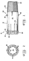
Fig. 1 is an elevational view of a pipe nipple in accordance with the present invention; -
Fig. 2 is an end view of the pipe nipple shown inFig. 1 ; -
Fig. 3 is an elevational view similar to that ofFig. 1 , but illustrating a second embodiment of the present invention; and -
Fig. 4 is an end view of the pipe nipple shown inFig. 3 . - Before the embodiments of the invention are explained in detail, it is to be understood that the invention is not limited in its application to the details of construction and the arrangements of the components set forth in the following description or illustrated in the drawings, but is defined by the appended claims.
- Referring now more specifically to the drawings and to
Fig. 1 in particular,numeral 10 designates a pipe nipple in accordance with the present invention. Nipple 10 is particularly suited for use as a nipple in an automotive cooling system, to serve as a transition between, for example, a hose of the cooling system and a water pump in the cooling system. However, it should be understood that pipe nipples in accordance with the present invention can be used for other purposes within automotive cooling system and for other fluid systems of other types. - Nipple 10 is an elongated, generally
annular body 12 having anexterior surface 14 and anaxial bore 16 defined by aninterior surface 18. Nipple 10 is formed of steel or other metals by known cold forming processes such as, for example, eyelet forming or metal drawing. Using punches, dies and the like without machining or cutting to form the elongated structure ofbody 12 eliminates contact by cutting tools oninterior surface 18. Thereby, scratches are not formed oninterior surface 18, and corrosive components do not accumulate thereon. Further, fluid flows smoothly and efficiently alonginterior surface 18 with reduced drag from the reduced presence of surface irregularities. -
Body 12 has afirst end 20 and asecond end 22. A portion ofexterior surface 14 fromfirst end 20 inwardly towardsecond end 22 is provided with apipe thread 24.Pipe thread 24 is of a pitch and depth to engage female threads in a fluid system component to which nipple 10 is to be attached. For example,pipe threads 24 can be provided to engage a threaded port of a water pump (not shown). -
Second end 22 is adapted to receive thereon a hose (not shown) of an automotive cooling system.Second end 22 is provided with a radially extendingcircumferential flange 26 slightly inwardly from anouter edge 28 ofsecond end 22. Aramp surface 30 is provided betweenouter edge 28 andflange 26. The diameter ofnipple 10 atouter edge 28 is provided to readily receive and align a hose (not shown) to be inserted thereon. However, the diameter offlange 26 is slightly larger than the inside diameter of the hose (not shown), causing the house to stretch as it is slid overflange 26.Exterior surface 14 is provided of a diameter to snuggly engage the hose. - For rotating
nipple 10 about its longitudinal axis, to drive the nipple relative to the threaded member to which nipple 10 is connected, adrive configuration 40 is provided inbore 16 fromsecond end 22 inwardly towardfirst end 20. In the embodiment shown inFig. 2 ,nipple 10 is provided with sixcomer points 42 by which a hexagonal drive tool can be inserted intobore 16 for rotatingnipple 10. As compared with prior known nipples, driveconfiguration 40 can be of significantly longer length. Further, with anend drive configuration 40 ratcheting tools or other powered rotary tools are more easily used for rotatingnipple 10. -
Exterior surface 14 is provided with one ormore surface formations 44, such as a plurality of outwardly extendingwings 46, which provide both a visual and physical indication when a hose (not shown) has been sufficiently applied overnipple 10. With a hose (not shown) applied with its end againstwings 46, a ring clamp or hose clamp (not shown) can encircle the hose betweenwings 46 andflange 26 to properly seal the hose against the nipple in a fluid tight connection. -
Fig. 3 illustrates anipple 50 also in accordance with the present invention.Nipple 50 is similar tonipple 10, as evidenced by the similar numerals indicating similar parts and features betweennipples nipple 50 includes adifferent surface formation 44. Acircumferential ring 52 is provided instead ofwings 46.Ring 52 serves a similar purpose aswings 46, providing a stop against which the end of a hose (not shown) can be abutted. Acircumferential depression 54 is provided inexterior surface 14 immediatelyadjacent ring 52, at least on the side ofring 52 facing the hose (not shown) to be applied thereon.Depression 54 allows the end of the hose (not shown) to relax, thereby reducing the propensity for cracks to propagate inwardly in the hose from the outer end thereof. -
Surface formations 44, such aswings 46 andring 52, can be formed by metal pinching or other similar processes well known to those skilled in the metal forming arts. - In using either
nipple 10 ornipple 50,thread 24 is aligned with the mating threads of the component to whichnipple drive configuration 40, and is rotated to tighten the nipple. By drivingnipples exterior surface 14 thereof. The tool is easily seated properly indrive configuration 40, and the danger ofdamaging threads 24 or of the area ofexterior surface 14 on which a hose will be seated is reduced substantially. - To attach a hose to
second end 22, the hose is slid overramp surface 30 andflange 26. When the end of the hose approaches thesurface formation 44, such aswings 46 orring 52, the installer is assured that a sufficient length of the hose is present on the nipple to be properly sealed thereon by an appropriate clamp. Withnipple 50, the outer edge of the hose is positioned indepression 54, thereby relieving the strain of the hose stretched overbody 12. Crack origination and propagation inwardly from the end of the hose is reduced. - The present invention provides an improved automotive cooling system pipe nipple which is more easily driven for engagement with other cooling system components and which eliminates scratches on fluid contacting surfaces which can form corrosion sites and inhibit fluid flow there along. Further, the invention provides both a physical and visual indication when a hose has been applied over the nipple a length sufficient for proper engagement by a clamp ring used to secure the hose on the nipple. In one embodiment of the invention the end of a hose applied on the nipple is allowed to relax to reduce crack formation and crack propagation.
- Various features of the invention are set forth in the following claims.
Claims (14)
- A method of manufacturing a pipe nipple (10) for an automobile cooling system, comprising:cold-forming a tubular body (12) having first and second ends (20, 22) and a bore (16) there through from said first end (20) to said second end (22), including:threading a portion (24) of said body (12) from said first end (20) inwardly toward said second end (22);forming an outwardly extending flange (26) at said second end (22); andshaping said bore (16) from said second end (22) inwardly toward said first end (20) to provide a drive configuration (40) in said bore (16) from said second end (22) inwardly toward said first end (20) for receiving a tool therein for rotating said nipple (10) about a longitudinal axis of the nipple (10).
- The method of claim 1, said shaping step including forming corners (42) in said bore (16) for receiving a hex tool therein.
- The method of claim 1 or 2, including forming an outwardly extending formation (44) on said nipple (10) between and spaced from said first and second ends (20, 22).
- The method of claim 3, including forming a plurality of outwardly extending wings (46) as said formation (44).
- The method of claim 3, including forming a circumferential ring (52) as said formation (44).
- The method of claim 5, including forming a circumferential depression (54) adjacent said ring (52) toward said second end.
- A nipple comprising:a tubular body (12) having an outer surface (14), first and second ends (20, 22) and a longitudinal bore (16) there through;said first end (20) having threads (24) thereon;said second end (22) having an outwardly extending flange (26) and being configured to receive a hose thereon;characterized in thatsaid bore (16) comprises at said second end (22) a drive configuration (40) in said bore from said second end (22) inwardly toward said first end (20) for receiving a tool therein for rotating said nipple (10) about a longitudinal axis of the nipple.
- The nipple of claim 7, said bore (16) being configured at said second end (22) for receiving a hex tool therein.
- The nipple of claim 7 or 8, said outer surface (14) of said nipple (10) having at least one outwardly extending formation (44) between said threads (24) and said flange (26) functioning as a stop for a hose inserted on said nipple (10).
- The nipple of claim 9, said at least one formation (44) including a plurality of spaced wings (46).
- The nipple of claim 9, said at least one formation (44) including a circumferential ring (52) about said nipple (10).
- The nipple of claim 11, including a circumferential depression (54) adjacent said circumferential ring (52) on a side of said ring (52) toward said second end (22).
- The nipple of at least one of claims 7 to 12, made by cold forming.
- The nipple according to at least one of claims 7 to 13, wherein:said nipple (10) is a pipe nipple (10) for an automobile cooling system;said threads (24) of said first end (20) are adapted for engagement with threads of a cooling system componentsaid second end (22) is adapted to be received in a cooling system hose.
Applications Claiming Priority (4)
| Application Number | Priority Date | Filing Date | Title |
|---|---|---|---|
| US460127 | 1999-12-13 | ||
| US41074502P | 2002-09-13 | 2002-09-13 | |
| US410745P | 2002-09-13 | ||
| US10/460,127 US20040051311A1 (en) | 2002-09-13 | 2003-06-12 | Pipe nipple |
Publications (2)
| Publication Number | Publication Date |
|---|---|
| EP1398558A1 EP1398558A1 (en) | 2004-03-17 |
| EP1398558B1 true EP1398558B1 (en) | 2008-11-12 |
Family
ID=31891547
Family Applications (1)
| Application Number | Title | Priority Date | Filing Date |
|---|---|---|---|
| EP20030019139 Expired - Lifetime EP1398558B1 (en) | 2002-09-13 | 2003-08-23 | Pipe nipple and method of manufacturing the same |
Country Status (6)
| Country | Link |
|---|---|
| US (3) | US20040051311A1 (en) |
| EP (1) | EP1398558B1 (en) |
| KR (1) | KR100969306B1 (en) |
| CA (1) | CA2440547C (en) |
| DE (1) | DE60324637D1 (en) |
| MX (1) | MXPA03008150A (en) |
Families Citing this family (6)
| Publication number | Priority date | Publication date | Assignee | Title |
|---|---|---|---|---|
| US20080185836A1 (en) * | 2007-02-06 | 2008-08-07 | Accudyn Products, Inc. | Pipe Nipple |
| US20090114652A1 (en) * | 2007-11-07 | 2009-05-07 | Nilsen Martin J | Threaded connection element |
| CN102152067A (en) * | 2010-12-21 | 2011-08-17 | 重庆巨泰机械有限公司 | Gas tube joint of gas meter and machining process of gas tube joint |
| CN203099146U (en) * | 2012-04-25 | 2013-07-31 | 中天奥克产品有限公司 | Fluid accessory |
| US20140353965A1 (en) * | 2012-05-11 | 2014-12-04 | Higashio Mech Co., Ltd. | Pipe joint |
| US10722324B2 (en) * | 2018-01-08 | 2020-07-28 | Stoma Ventures, LLC | Adapter for a tailpiece for a dental valve |
Family Cites Families (45)
| Publication number | Priority date | Publication date | Assignee | Title |
|---|---|---|---|---|
| US230895A (en) | 1880-08-10 | Leather-splitting machine | ||
| US651134A (en) * | 1900-01-19 | 1900-06-05 | John Dickens | Swivel connection. |
| US1343967A (en) * | 1918-11-15 | 1920-06-22 | New York Belting & Packing Com | Hose-coupling |
| US1528967A (en) * | 1920-11-27 | 1925-03-10 | Martin C Bersted | Flexible conduit |
| US1509802A (en) * | 1920-12-24 | 1924-09-23 | Joseph F Weigand | Hose coupling |
| FR810096A (en) | 1936-08-11 | 1937-03-15 | Pipe fittings | |
| US2139745A (en) * | 1937-04-07 | 1938-12-13 | Howard W Goodall | Hose coupling |
| US2333350A (en) * | 1942-08-22 | 1943-11-02 | Weatherhead Co | Hose coupling |
| US2468338A (en) * | 1944-08-11 | 1949-04-26 | Resistoflex Corp | Hose coupling |
| US3479713A (en) * | 1964-10-27 | 1969-11-25 | Weatherhead Co | Method of making a hose coupling |
| US3408092A (en) * | 1967-04-13 | 1968-10-29 | Appleton Electric Co | Single piece connector for flexible hosing |
| US3684319A (en) * | 1970-05-27 | 1972-08-15 | Tasco Eng & Supply Inc | Hose end coupling |
| US3874714A (en) * | 1972-10-25 | 1975-04-01 | Westinghouse Electric Corp | Fitting for water supply arrangement |
| US3992044A (en) * | 1974-11-29 | 1976-11-16 | Specialty Connector Corporation | Flexible metal conduit with sealed end connectors |
| US4018459A (en) * | 1975-07-30 | 1977-04-19 | Reed Irrigation Systems | Submain connector |
| US4163573A (en) * | 1977-02-28 | 1979-08-07 | Chiyoda Tsusho K.K. | Hose fitting |
| JPS5829437B2 (en) * | 1980-07-24 | 1983-06-22 | トヨタ自動車株式会社 | Pipe fitting with cooling fins |
| US4412693A (en) * | 1981-07-31 | 1983-11-01 | Sergio Campanini | Swivel hose coupling with threaded nipple |
| US4457544A (en) * | 1981-08-13 | 1984-07-03 | Liquid Tight Corporation | Connector for flexible electrical conduit |
| DE3220945C2 (en) * | 1982-06-03 | 1984-11-22 | Josef Gartner & Co, 8883 Gundelfingen | Weld-free connection |
| US4519636A (en) * | 1982-10-20 | 1985-05-28 | Koomey, Inc. | Seal for an underwater connector |
| FR2552851B1 (en) * | 1983-09-30 | 1986-08-14 | Poutrait Morin | NOZZLES FOR FIXING AT THE END OF A FLEXIBLE DUCT, TO CONSTITUTE A CONNECTION FOR USE ON A PORTABLE PUMP FOR INFLATING TIRES, AND CONNECTION COMPRISING SUCH A NOZZLE |
| JPS60174302A (en) * | 1984-02-20 | 1985-09-07 | Tsukiboshi Seisakusho:Kk | Nipple for car |
| US4733890A (en) * | 1984-07-09 | 1988-03-29 | Stratoflex, Inc. | Formed fluid coupling apparatus |
| IT8583626A0 (en) * | 1985-11-25 | 1985-11-25 | Vulcano Di Pozzi Gian Carlo | "UNISEX" SELF-LOCKING FITTING WITH "CLIK" FOR QUICK CONNECTION OF PLASTIC HOSES. |
| US4817997A (en) * | 1987-06-25 | 1989-04-04 | Ingram Thomas L | Hose coupling |
| FR2652773A1 (en) * | 1989-10-11 | 1991-04-12 | Metaplast | Method of obtaining a flanged bush, especially intended for the connection of a pipe to a coupling, and device for its implementation |
| CN1053024A (en) | 1991-02-11 | 1991-07-17 | 上海有色金属研究所 | Cold forming method for metal pipe fitting by alkane filling |
| US5317799A (en) * | 1992-06-26 | 1994-06-07 | Dayco Products, Inc. | Method of making hose coupling with ferrule end bent over insert |
| US5240291A (en) * | 1992-07-06 | 1993-08-31 | Zornow Jeffrey S | Sanitary hose coupler |
| US5462317A (en) * | 1994-03-23 | 1995-10-31 | Keller; Wilhelm A. | Adapter for a mixing or dispensing device |
| US5537721A (en) | 1994-08-19 | 1996-07-23 | Hans Oetiker Ag Maschinen- Und Apparatefabrik | Tolerance-compensating hose clamp |
| US5487571A (en) * | 1994-08-29 | 1996-01-30 | Robertson; Duane D. | Pipe fitting |
| JP3445858B2 (en) * | 1994-12-29 | 2003-09-08 | 臼井国際産業株式会社 | Automotive metal piping with a protective coating layer |
| US6102442A (en) * | 1995-02-24 | 2000-08-15 | Arlington Industries, Inc. | Waterlight fitting for flexible conduit |
| US5636887A (en) * | 1995-03-20 | 1997-06-10 | Chrysler Corporation | Apparatus for lifting objects by suction and releasing them by gas pressure |
| CA2189406C (en) * | 1996-11-01 | 2007-01-23 | Istvan Feher | Coupling for composite hose and method of making same |
| US5951064A (en) * | 1997-09-02 | 1999-09-14 | Diebolt International, Inc. | Modular fluid control panel and connector fittings |
| IT1294764B1 (en) | 1997-09-03 | 1999-04-12 | Manuli Rubber Ind Spa | HIGH PRESSURE FITTING FOR RUBBER HOSES WITH IMPROVED SEALING CHARACTERISTICS |
| CN2313518Y (en) | 1997-11-25 | 1999-04-14 | 崔源湘 | Mixing valve of shower with adjustable central gaps and changeable directions |
| US6109659C1 (en) * | 1998-06-12 | 2002-02-26 | Power Transmission Tech | Hydrostatic rotary union |
| US6116573A (en) * | 1998-12-22 | 2000-09-12 | Cornette Technology, Llc | Packing system for valves |
| US6302451B1 (en) * | 2000-03-15 | 2001-10-16 | Dana Corporation | Quick-connect hose end couplings |
| KR100426334B1 (en) * | 2002-04-03 | 2004-04-08 | 주식회사 대우화스너 | manufacturing method of nipple for the wheel |
| US6719330B2 (en) * | 2002-06-18 | 2004-04-13 | Qest | Flexible tubing/fitting connection |
-
2003
- 2003-06-12 US US10/460,127 patent/US20040051311A1/en not_active Abandoned
- 2003-08-23 DE DE60324637T patent/DE60324637D1/en not_active Expired - Lifetime
- 2003-08-23 EP EP20030019139 patent/EP1398558B1/en not_active Expired - Lifetime
- 2003-09-05 KR KR1020030062274A patent/KR100969306B1/en not_active IP Right Cessation
- 2003-09-09 MX MXPA03008150A patent/MXPA03008150A/en active IP Right Grant
- 2003-09-11 CA CA 2440547 patent/CA2440547C/en not_active Expired - Fee Related
-
2004
- 2004-09-09 US US10/936,859 patent/US7503588B2/en not_active Expired - Fee Related
-
2005
- 2005-08-12 US US11/202,661 patent/US20050285388A1/en not_active Abandoned
Also Published As
| Publication number | Publication date |
|---|---|
| US20050285388A1 (en) | 2005-12-29 |
| CA2440547A1 (en) | 2004-03-13 |
| KR20040024476A (en) | 2004-03-20 |
| CA2440547C (en) | 2009-04-14 |
| KR100969306B1 (en) | 2010-07-09 |
| DE60324637D1 (en) | 2008-12-24 |
| US20040051311A1 (en) | 2004-03-18 |
| EP1398558A1 (en) | 2004-03-17 |
| US20050029803A1 (en) | 2005-02-10 |
| MXPA03008150A (en) | 2004-03-19 |
| US7503588B2 (en) | 2009-03-17 |
Similar Documents
| Publication | Publication Date | Title |
|---|---|---|
| US11143226B2 (en) | Two-piece blind fastener | |
| JP4663713B2 (en) | Conduit fitting with pull-up indication | |
| EP2069646B1 (en) | Threaded fastener with predetermined torque | |
| EP1262702B1 (en) | Method and structure for preventing slipping-off of a tube in a pipe joint made of resin | |
| EP2350514B1 (en) | Pipe joint | |
| US20140353969A1 (en) | Tube connection structure | |
| US6581981B2 (en) | Pipe-fitting with flexible sleeve and cinching nut | |
| US20050285388A1 (en) | Pipe nipple | |
| US20130153063A1 (en) | Hydraulic Fitting For Bulkhead Mounting With Key Shaped Cross Section | |
| CN109073120B (en) | Catheter fitting with travel impedance feature | |
| US10955074B2 (en) | Threaded pipe connections and sockets for making the same in situ | |
| US6598286B1 (en) | Metal tube coupling arrangement and method of manufacture | |
| CA2324175A1 (en) | Swivel coupling and meyhod for attaching a swivel nut to a tail piece | |
| RU2621429C2 (en) | Pipe fitting | |
| US20030197379A1 (en) | Multi-sealing compression fitting for plumbing connections | |
| CN216343296U (en) | Stud and fastening assembly | |
| CN219692577U (en) | Tee joint | |
| JP4198429B2 (en) | Pipe retaining ring for thin-walled pipe joint and joint structure using the same | |
| KR102343225B1 (en) | Thermal cycle resistant fastening system for refrigerant fitting | |
| CN100425899C (en) | Pipe nipple | |
| JP2003254476A (en) | Mechanical pipe joint | |
| US20090039645A1 (en) | Fitting and tube assembly for refrigeration systems | |
| WO2008040977A1 (en) | Threaded fastener with predetermined torque |
Legal Events
| Date | Code | Title | Description |
|---|---|---|---|
| PUAI | Public reference made under article 153(3) epc to a published international application that has entered the european phase |
Free format text: ORIGINAL CODE: 0009012 |
|
| AK | Designated contracting states |
Kind code of ref document: A1 Designated state(s): AT BE BG CH CY CZ DE DK EE ES FI FR GB GR HU IE IT LI LU MC NL PT RO SE SI SK TR |
|
| AX | Request for extension of the european patent |
Extension state: AL LT LV MK |
|
| 17P | Request for examination filed |
Effective date: 20040730 |
|
| AKX | Designation fees paid |
Designated state(s): DE FR GB IT |
|
| 17Q | First examination report despatched |
Effective date: 20070122 |
|
| GRAP | Despatch of communication of intention to grant a patent |
Free format text: ORIGINAL CODE: EPIDOSNIGR1 |
|
| GRAS | Grant fee paid |
Free format text: ORIGINAL CODE: EPIDOSNIGR3 |
|
| GRAA | (expected) grant |
Free format text: ORIGINAL CODE: 0009210 |
|
| AK | Designated contracting states |
Kind code of ref document: B1 Designated state(s): DE FR GB IT |
|
| REG | Reference to a national code |
Ref country code: GB Ref legal event code: FG4D |
|
| REF | Corresponds to: |
Ref document number: 60324637 Country of ref document: DE Date of ref document: 20081224 Kind code of ref document: P |
|
| PLBE | No opposition filed within time limit |
Free format text: ORIGINAL CODE: 0009261 |
|
| STAA | Information on the status of an ep patent application or granted ep patent |
Free format text: STATUS: NO OPPOSITION FILED WITHIN TIME LIMIT |
|
| 26N | No opposition filed |
Effective date: 20090813 |
|
| PGFP | Annual fee paid to national office [announced via postgrant information from national office to epo] |
Ref country code: GB Payment date: 20110825 Year of fee payment: 9 Ref country code: FR Payment date: 20110830 Year of fee payment: 9 Ref country code: DE Payment date: 20110830 Year of fee payment: 9 |
|
| PGFP | Annual fee paid to national office [announced via postgrant information from national office to epo] |
Ref country code: IT Payment date: 20110823 Year of fee payment: 9 |
|
| GBPC | Gb: european patent ceased through non-payment of renewal fee |
Effective date: 20120823 |
|
| REG | Reference to a national code |
Ref country code: FR Ref legal event code: ST Effective date: 20130430 |
|
| PG25 | Lapsed in a contracting state [announced via postgrant information from national office to epo] |
Ref country code: IT Free format text: LAPSE BECAUSE OF NON-PAYMENT OF DUE FEES Effective date: 20120823 |
|
| PG25 | Lapsed in a contracting state [announced via postgrant information from national office to epo] |
Ref country code: GB Free format text: LAPSE BECAUSE OF NON-PAYMENT OF DUE FEES Effective date: 20120823 Ref country code: DE Free format text: LAPSE BECAUSE OF NON-PAYMENT OF DUE FEES Effective date: 20130301 |
|
| PG25 | Lapsed in a contracting state [announced via postgrant information from national office to epo] |
Ref country code: FR Free format text: LAPSE BECAUSE OF NON-PAYMENT OF DUE FEES Effective date: 20120831 |
|
| REG | Reference to a national code |
Ref country code: DE Ref legal event code: R119 Ref document number: 60324637 Country of ref document: DE Effective date: 20130301 |