EP1398465A1 - Turbolader und Rotorgehäuse hierfür - Google Patents
Turbolader und Rotorgehäuse hierfür Download PDFInfo
- Publication number
- EP1398465A1 EP1398465A1 EP02020411A EP02020411A EP1398465A1 EP 1398465 A1 EP1398465 A1 EP 1398465A1 EP 02020411 A EP02020411 A EP 02020411A EP 02020411 A EP02020411 A EP 02020411A EP 1398465 A1 EP1398465 A1 EP 1398465A1
- Authority
- EP
- European Patent Office
- Prior art keywords
- rotor
- housing
- turbocharger
- channel
- axis
- Prior art date
- Legal status (The legal status is an assumption and is not a legal conclusion. Google has not performed a legal analysis and makes no representation as to the accuracy of the status listed.)
- Granted
Links
Images

Classifications
-
- F—MECHANICAL ENGINEERING; LIGHTING; HEATING; WEAPONS; BLASTING
- F01—MACHINES OR ENGINES IN GENERAL; ENGINE PLANTS IN GENERAL; STEAM ENGINES
- F01D—NON-POSITIVE DISPLACEMENT MACHINES OR ENGINES, e.g. STEAM TURBINES
- F01D25/00—Component parts, details, or accessories, not provided for in, or of interest apart from, other groups
- F01D25/24—Casings; Casing parts, e.g. diaphragms, casing fastenings
-
- F—MECHANICAL ENGINEERING; LIGHTING; HEATING; WEAPONS; BLASTING
- F01—MACHINES OR ENGINES IN GENERAL; ENGINE PLANTS IN GENERAL; STEAM ENGINES
- F01D—NON-POSITIVE DISPLACEMENT MACHINES OR ENGINES, e.g. STEAM TURBINES
- F01D9/00—Stators
- F01D9/02—Nozzles; Nozzle boxes; Stator blades; Guide conduits, e.g. individual nozzles
- F01D9/026—Scrolls for radial machines or engines
-
- F—MECHANICAL ENGINEERING; LIGHTING; HEATING; WEAPONS; BLASTING
- F02—COMBUSTION ENGINES; HOT-GAS OR COMBUSTION-PRODUCT ENGINE PLANTS
- F02C—GAS-TURBINE PLANTS; AIR INTAKES FOR JET-PROPULSION PLANTS; CONTROLLING FUEL SUPPLY IN AIR-BREATHING JET-PROPULSION PLANTS
- F02C6/00—Plural gas-turbine plants; Combinations of gas-turbine plants with other apparatus; Adaptations of gas-turbine plants for special use
- F02C6/04—Gas-turbine plants providing heated or pressurised working fluid for other apparatus, e.g. without mechanical power output
- F02C6/10—Gas-turbine plants providing heated or pressurised working fluid for other apparatus, e.g. without mechanical power output supplying working fluid to a user, e.g. a chemical process, which returns working fluid to a turbine of the plant
- F02C6/12—Turbochargers, i.e. plants for augmenting mechanical power output of internal-combustion piston engines by increase of charge pressure
-
- F—MECHANICAL ENGINEERING; LIGHTING; HEATING; WEAPONS; BLASTING
- F05—INDEXING SCHEMES RELATING TO ENGINES OR PUMPS IN VARIOUS SUBCLASSES OF CLASSES F01-F04
- F05D—INDEXING SCHEME FOR ASPECTS RELATING TO NON-POSITIVE-DISPLACEMENT MACHINES OR ENGINES, GAS-TURBINES OR JET-PROPULSION PLANTS
- F05D2220/00—Application
- F05D2220/40—Application in turbochargers
Definitions
- the present invention relates to a turbocharger with a rotor shaft, which defines an axis of rotation, a turbine housing with at least one feed channel for exhaust gas, in which turbine housing an end of the rotor shaft protrudes, and in which at least one turbine rotor attached to this rotor shaft and so in a predetermined first plane perpendicular to the axis of rotation within a first rotor space is rotatably mounted and the periphery of which the exhaust gas can be fed.
- the Turbocharger a compressor housing with at least one supply duct for air on, in which protrudes the other end of the rotor shaft, on which at least one compressor rotor in a. predetermined second plane perpendicular to the axis of rotation within a second rotor space is attached and the periphery of which the air can be fed.
- the object of the invention is to achieve burst protection in a simple manner, provide without additional measures and / or thick housing walls must load the turbocharger by weight and make production more expensive.
- At least one of the supply channels is axially offset from the respective plane of the associated rotor and has a duct branch leading to the rotor space, the radially outer duct wall of which transferred obliquely from the rotor space to the feed channel. Due to the sloping channel wall In the event of a rotor bursting, the trajectory is deflected by rotor parts, one part of the energy inherent in such parts is reduced. So that the remaining Residual energy can easily be absorbed on the outer casing of the respective housing without to penetrate the housing. Therefore, such housings can by the invention are made thinner and do not require any additional burst protection measures.
- the turbine rotor in particular is subjected to a load is because it is also exposed to a corrosive load. Therefore it is preferred if it is at least the supply duct for exhaust gas which is the inclined Has channel wall.
- the sloping duct wall to the axis of rotation takes an angle of at least 45 °, preferably at least 60 °.
- the angle can also be steeper, for example 75 ° to reach.
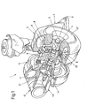
- a turbocharger 1 has a turbine housing part 2 and an associated compressor housing part 3, which along an axis of rotation R are arranged.
- the turbine housing part 2 is partially shown in section, so that the on the axis R located turbine rotor 4 is visible, the one end of a rotor shaft 5 is attached, which is mounted in a middle part 6 of the housing.
- the turbine housing 2 has a supply nozzle 7 for exhaust gas, which flows into an approximately annular supply channel 9 for exhaust gas flows out or continues in this, to the turbine rotor 4 exhaust gas from a Feed internal combustion engine.
- the feed takes place in the embodiment shown via the blades 8 of a known (and therefore not described here in detail) Guide grid of variable geometry, which is mounted in a vane bearing ring 10 Adjustment shafts in terms of their position (more radial to the rotor 4 or more tangential) are adjustable.
- the position of these blades 8 controls the supply amount of exhaust gas Turbine rotor 4, but it is known from the literature that this supply amount also through other gas control devices, such as the discharge of the exhaust gas via one on the turbine housing passing shunt can be regulated via a corresponding valve can.
- more than one feed channel 9 can also be provided, in particular if several turbine rotors should be attached to the shaft 5.
- the turbine rotor 4 is on the same rotor shaft 5 at the other end, driven compressor rotor 21 driven.
- This compressor rotor sucks air through a supply channel 11 surrounding it and an attached one Feed pipe 12, compresses it and blows it out through an axial pipe 13 '.
- the turbine housing 2 also has an axial connection 13 ".
- a rotor housing 20 is now shown with reference to FIG. 2, which for example (and preferably) instead of the housing 2 of FIG. 1, but possibly in a similar form also for the housing 3, should be used to the turbocharger shown in Fig. 1 to make a turbocharger according to the invention.
- This housing 20 extends along a longitudinal axis R ', which also corresponds approximately to the axis of rotation R according to FIG. 1.
- a central plane P running perpendicular to this corresponds to the central plane of the one Rotor (4 or 21), which is to be used in this housing 20.
- the middle plane P accordingly passes through a space 23 in which the respective rotor 4 or 21 rotates.
- this rotor space 23 is radially outside of an inclined channel wall 24 limited.
- This sloping channel wall 24 results from the fact that the feed channel 9/11 is clearly axially offset from the plane P. Therefore, the respective gas is supplied not directly via the feed channel 9/11, but via an inclined channel branch 25 which Gas leads from the feed channel 9/11 into the rotor space 23. If now the respective rotor in its rotor chamber 23 rotates and should burst due to the centrifugal force, so his pieces fly radially outwards in relation to the axis R 'and initially hit on the inclined wall 24, which makes an angle ⁇ and a complementary angle ß with the longitudinal axis corresponding to the axis of rotation R. R 'a.
- This latter angle should preferably be at least 45 °, expediently at least 60 °.
- the inclined wall 24 thus destroys part of the impact energy broken rotor piece without being exposed to excessive stress, because the impact is deflected towards the feed channel 9/11. So extended but also the distance of the trajectory, whereby further impact energy is lost. Then when a burst part finally hits the inside wall of the feed channel, it is Residual energy is already so small that damage to the housing wall is no longer possible is possible. Therefore, the housing 20 can be compared to conventional housings be relatively thin-walled - and thus also more cost-effective.
- FIG. 2 relates to the arrangement shown in FIG. 1, see above there are of course two rotor spaces (one for the rotor 4, one for the rotor 21) axially offset from one another, the rotors 4, 21 each being assigned a separate rotor space which corresponds to the rotor space 23 of FIG. 2.
Landscapes
- Engineering & Computer Science (AREA)
- Mechanical Engineering (AREA)
- General Engineering & Computer Science (AREA)
- Chemical & Material Sciences (AREA)
- Chemical Kinetics & Catalysis (AREA)
- General Chemical & Material Sciences (AREA)
- Combustion & Propulsion (AREA)
- Supercharger (AREA)
Abstract
Description
- Fig. 1
- zeigt einen Turbolader der bisherigen Bauart in Perspektivansicht, teilweise im Schnitt, und
- Fig. 2
- einen Axialschnitt durch ein erfindungsgemäß ausgebildetes Gehäuse für einen Turbolader nach Fig. 1.
Claims (9)
- Turbolader (1), der folgendes aufweist:dadurch gekennzeichnet, daßeine Rotorwelle (5), die eine Rotationsachse (R; R') definiert,ein Turbinengehäuse (2; 20) mit mindestens einem Zufuhrkanal (9) für Abgas, in welches ein Ende der Rotorwelle (5) ragt, und in welchemmindestens ein Turbinenrotor (4) an dieser Rotorwelle (5) befestigt und so in einer vorbestimmten ersten, zur Rotationsachse (R, R') senkrechten Ebene (P) innerhalb eines ersten Rotorraumes (23) drehbar gelagert ist und dessen Peripherie das Abgas zuführbar ist,ein Kompressorgehäuse (3) mit mindestens einem Zufuhrkanal (11) für Luft, in welches das andere Ende der Rotorwelle (5) ragt, an demwenigstens ein Kompressorrotor (21) in einer vorbestimmten zweiten, zur Rotationsachse (R; R') senkrechten Ebene (P) innerhalb eines zweiten Rotorraumes (23) befestigt ist und dessen Peripherie die Luft zuführbar ist,
mindestens einer der Zufuhrkanäle (9, 11) gegenüber der jeweiligen Ebene (P) des zugehörigen Rotors (4, 21) axial versetzt angeordnet ist und wenigstens einen zum Rotorraum (23) führenden Kanalast (25) aufweist, dessen radial äußere Kanalwand (24) vom Rotorraum (23) zum Zufuhrkanal (9, 11) schräg überleitet. - Turbolader (1) nach Anspruch 1, dadurch gekennzeichnet, daß es wenigstens der Zufuhrkanal (9) für Abgas ist, welcher die schräge Kanalwand (24) aufweist.
- Turbolader (1) nach Anspruch 1 oder 2, dadurch gekennzeichnet, daß die schräge Kanalwand (24) zur Rotationsachse (R') einen Winkel (ß) von mindestens 45° einnimmt.
- Turbolader (1) nach Anspruch 3, dadurch gekennzeichnet, daß die schräge Kanalwand (24) zur Rotationsachse (R') einen Winkel (ß) von mindestens 60° einnimmt.
- Turbolader (1) nach einem der vorhergehenden Ansprüche, dadurch gekennzeichnet, daß der jeweilige Zufuhrkanal (9, 11) gegen den Mittelteil (6) des gesamten Gehäuses (2, 3, 6) versetzt ist.
- Rotorgehäuse (20) für einen Turbolader (1) nach einem der vorhergehenden Ansprüche, mit einem Raum (23) zur Aufnahme eines Rotors (4, 21) koaxial zu seiner Längsachse (R'), welcher Raum (23) in einer zur Längsachse (R') senkrechten Ebene (P) liegt, im Bereich welcher Ebene (P) auch rund um den Raum (23) zur Aufnahme eines Rotors (4, 21) ein Zufuhrkanal (9, 11) für ein Gas vorgesehen ist dadurch gekennzeichnet, daß der Zufuhrkanal (9/11) gegenüber der jeweiligen Ebene (P) des zugehörigen Rotors (4, 21) axial versetzt ist und wenigstens einen zum Rotorraum (23) führenden Kanalast (25) aufweist, dessen radial äußere Kanalwand (24) vom Rotorraum (23) zum Zufuhrkanal (9) schräg überleitet.
- Rotorgehäuse (20) nach Anspruch 6, dadurch gekennzeichnet, daß die schräge Kanalwand (24) zur Längsachse (R') einen Winkel (ß) von mindestens 45° einnimmt.
- Rotorgehäuse (20) nach Anspruch 7, dadurch gekennzeichnet, daß die schräge Kanalwand (24) zur Längsachse (R') einen Winkel (ß) von mindestens 60° einnimmt.
- Rotorgehäuse (20) nach einem der Ansprüche 5 bis 8, dadurch gekennzeichnet, daß der jeweilige Zufuhrkanal (9/11) gegen den Mittelteil (6) des gesamten Gehäuses (2, 3, 6) versetzt ist.
Priority Applications (3)
| Application Number | Priority Date | Filing Date | Title |
|---|---|---|---|
| EP20020020411 EP1398465B1 (de) | 2002-09-10 | 2002-09-10 | Turbolader und Rotorgehäuse hierfür |
| DE50203152T DE50203152D1 (de) | 2002-09-10 | 2002-09-10 | Turbolader und Rotorgehäuse hierfür |
| JP2003309840A JP2004132366A (ja) | 2002-09-10 | 2003-09-02 | ターボチャージャー及びそれのためのローターハウジング |
Applications Claiming Priority (1)
| Application Number | Priority Date | Filing Date | Title |
|---|---|---|---|
| EP20020020411 EP1398465B1 (de) | 2002-09-10 | 2002-09-10 | Turbolader und Rotorgehäuse hierfür |
Publications (2)
| Publication Number | Publication Date |
|---|---|
| EP1398465A1 true EP1398465A1 (de) | 2004-03-17 |
| EP1398465B1 EP1398465B1 (de) | 2005-05-18 |
Family
ID=31725404
Family Applications (1)
| Application Number | Title | Priority Date | Filing Date |
|---|---|---|---|
| EP20020020411 Expired - Lifetime EP1398465B1 (de) | 2002-09-10 | 2002-09-10 | Turbolader und Rotorgehäuse hierfür |
Country Status (3)
| Country | Link |
|---|---|
| EP (1) | EP1398465B1 (de) |
| JP (1) | JP2004132366A (de) |
| DE (1) | DE50203152D1 (de) |
Cited By (1)
| Publication number | Priority date | Publication date | Assignee | Title |
|---|---|---|---|---|
| US9255485B2 (en) | 2011-02-02 | 2016-02-09 | Mitsubishi Heavy Industries, Ltd. | Turbine housing made of sheet metal |
Families Citing this family (1)
| Publication number | Priority date | Publication date | Assignee | Title |
|---|---|---|---|---|
| JP5769407B2 (ja) | 2010-02-01 | 2015-08-26 | 三菱重工業株式会社 | 板金タービンハウジング |
Citations (4)
| Publication number | Priority date | Publication date | Assignee | Title |
|---|---|---|---|---|
| US4482304A (en) * | 1980-09-30 | 1984-11-13 | Aktiengesellschaft Kuhnle, Kopp & Kausch | Compressor of a type incorporated in an exhaust gas turbocharger |
| US4565505A (en) * | 1983-04-11 | 1986-01-21 | Woollenweber William E | Combination flow turbine for internal combustion engine turbochargers |
| EP0186389A1 (de) * | 1984-12-14 | 1986-07-02 | The Garrett Corporation | Geregeltes Wärmeübertragungssystem für einen Turbolader |
| US5094587A (en) * | 1990-07-25 | 1992-03-10 | Woollenweber William E | Turbine for internal combustion engine turbochargers |
-
2002
- 2002-09-10 DE DE50203152T patent/DE50203152D1/de not_active Expired - Fee Related
- 2002-09-10 EP EP20020020411 patent/EP1398465B1/de not_active Expired - Lifetime
-
2003
- 2003-09-02 JP JP2003309840A patent/JP2004132366A/ja not_active Withdrawn
Patent Citations (4)
| Publication number | Priority date | Publication date | Assignee | Title |
|---|---|---|---|---|
| US4482304A (en) * | 1980-09-30 | 1984-11-13 | Aktiengesellschaft Kuhnle, Kopp & Kausch | Compressor of a type incorporated in an exhaust gas turbocharger |
| US4565505A (en) * | 1983-04-11 | 1986-01-21 | Woollenweber William E | Combination flow turbine for internal combustion engine turbochargers |
| EP0186389A1 (de) * | 1984-12-14 | 1986-07-02 | The Garrett Corporation | Geregeltes Wärmeübertragungssystem für einen Turbolader |
| US5094587A (en) * | 1990-07-25 | 1992-03-10 | Woollenweber William E | Turbine for internal combustion engine turbochargers |
Cited By (1)
| Publication number | Priority date | Publication date | Assignee | Title |
|---|---|---|---|---|
| US9255485B2 (en) | 2011-02-02 | 2016-02-09 | Mitsubishi Heavy Industries, Ltd. | Turbine housing made of sheet metal |
Also Published As
| Publication number | Publication date |
|---|---|
| EP1398465B1 (de) | 2005-05-18 |
| DE50203152D1 (de) | 2005-06-23 |
| JP2004132366A (ja) | 2004-04-30 |
Similar Documents
| Publication | Publication Date | Title |
|---|---|---|
| DE69203705T2 (de) | Stator zur Einführung von Luft in das Innere einer Turbomaschine und Verfahren zum Montieren einer Schaufel dieses Stators. | |
| EP1502008B1 (de) | Befestigungsvorrichtung für ein laufrad auf einer welle | |
| EP0048012B1 (de) | Desintegrator und Verfahren zum Betrieb des Desintegrators | |
| EP1394364B1 (de) | Turbolader und Schaufellagerring hierfür | |
| DE3302576C2 (de) | Fangehäuse mit einer Schaufelbruchschutzeinrichtung für ein Axialgasturbinentriebwerk | |
| EP0834646A1 (de) | Berstschutzvorrichtung für Radialturbinen von Turboladern | |
| EP0834645B1 (de) | Verdichterradbefestigung für Turbolader | |
| DE2031612A1 (de) | Vielstufiger Axialkompressor mit einem Luftableitsystem als Zwischen stufe | |
| EP1383987A1 (de) | Berstschutzvorrichtung für radialverdichter von turboladern | |
| DE2648850B2 (de) | ||
| CH672941A5 (de) | ||
| EP0806547B1 (de) | Axialturbine eines Abgasturboladers | |
| DE102018113753A1 (de) | Planetengetriebe und Gasturbinentriebwerk | |
| DE102007028742A1 (de) | Luftversorger, insbesondere für ein Luftversorgungssystem von Brennstoffzellen | |
| DE3521798C2 (de) | Axialverdichter mit Pumpverhütungsmaßnahmen | |
| DE102005039820A1 (de) | Containment-Sicherung für Strömungsmaschinen mit radial durchströmten Verdichterrad | |
| EP1398465B1 (de) | Turbolader und Rotorgehäuse hierfür | |
| DE19847772B4 (de) | Schläger- oder Gebläseschlägermühle | |
| WO2008055717A1 (de) | Gehäuseverbindung eines abgasturboladers | |
| WO2012107193A1 (de) | Gehäuse für einen abgasturbolader mit berstschutz - knautschzone | |
| DE29917625U1 (de) | Vorrichtung zum Beeinflussen der Strömung im Einströmbereich von Strömungsmaschinen | |
| EP3153671A1 (de) | Schutzvorrichtung für eine strömungsmaschine | |
| DE102012212483A1 (de) | Zahnärztliches Präparationsinstrument | |
| DE19824421A1 (de) | Gehäuseausbildung an einer Gasturbine | |
| DE69808345T2 (de) | Verdichter mit zumindest einer verdichtungsstufe und einem feuchtigkeitsabscheider |
Legal Events
| Date | Code | Title | Description |
|---|---|---|---|
| PUAI | Public reference made under article 153(3) epc to a published international application that has entered the european phase |
Free format text: ORIGINAL CODE: 0009012 |
|
| AK | Designated contracting states |
Kind code of ref document: A1 Designated state(s): AT BE BG CH CY CZ DE DK EE ES FI FR GB GR IE IT LI LU MC NL PT SE SK TR |
|
| AX | Request for extension of the european patent |
Extension state: AL LT LV MK RO SI |
|
| RAP1 | Party data changed (applicant data changed or rights of an application transferred) |
Owner name: BORGWARNER, INC. |
|
| 17P | Request for examination filed |
Effective date: 20040430 |
|
| 17Q | First examination report despatched |
Effective date: 20040603 |
|
| GRAP | Despatch of communication of intention to grant a patent |
Free format text: ORIGINAL CODE: EPIDOSNIGR1 |
|
| AKX | Designation fees paid |
Designated state(s): DE FR GB IT NL |
|
| GRAS | Grant fee paid |
Free format text: ORIGINAL CODE: EPIDOSNIGR3 |
|
| GRAA | (expected) grant |
Free format text: ORIGINAL CODE: 0009210 |
|
| RAP1 | Party data changed (applicant data changed or rights of an application transferred) |
Owner name: BORGWARNER INC. |
|
| AK | Designated contracting states |
Kind code of ref document: B1 Designated state(s): DE FR GB IT NL |
|
| REG | Reference to a national code |
Ref country code: GB Ref legal event code: FG4D Free format text: NOT ENGLISH |
|
| GBT | Gb: translation of ep patent filed (gb section 77(6)(a)/1977) |
Effective date: 20050518 |
|
| REG | Reference to a national code |
Ref country code: IE Ref legal event code: FG4D Free format text: LANGUAGE OF EP DOCUMENT: GERMAN |
|
| REF | Corresponds to: |
Ref document number: 50203152 Country of ref document: DE Date of ref document: 20050623 Kind code of ref document: P |
|
| ET | Fr: translation filed | ||
| PLBE | No opposition filed within time limit |
Free format text: ORIGINAL CODE: 0009261 |
|
| STAA | Information on the status of an ep patent application or granted ep patent |
Free format text: STATUS: NO OPPOSITION FILED WITHIN TIME LIMIT |
|
| 26N | No opposition filed |
Effective date: 20060221 |
|
| PGFP | Annual fee paid to national office [announced via postgrant information from national office to epo] |
Ref country code: FR Payment date: 20080904 Year of fee payment: 7 Ref country code: IT Payment date: 20080916 Year of fee payment: 7 Ref country code: NL Payment date: 20080813 Year of fee payment: 7 |
|
| PGFP | Annual fee paid to national office [announced via postgrant information from national office to epo] |
Ref country code: GB Payment date: 20080808 Year of fee payment: 7 |
|
| PGFP | Annual fee paid to national office [announced via postgrant information from national office to epo] |
Ref country code: DE Payment date: 20080930 Year of fee payment: 7 |
|
| REG | Reference to a national code |
Ref country code: NL Ref legal event code: V1 Effective date: 20100401 |
|
| GBPC | Gb: european patent ceased through non-payment of renewal fee |
Effective date: 20090910 |
|
| REG | Reference to a national code |
Ref country code: FR Ref legal event code: ST Effective date: 20100531 |
|
| PG25 | Lapsed in a contracting state [announced via postgrant information from national office to epo] |
Ref country code: NL Free format text: LAPSE BECAUSE OF NON-PAYMENT OF DUE FEES Effective date: 20100401 Ref country code: FR Free format text: LAPSE BECAUSE OF NON-PAYMENT OF DUE FEES Effective date: 20090930 Ref country code: DE Free format text: LAPSE BECAUSE OF NON-PAYMENT OF DUE FEES Effective date: 20100401 |
|
| PG25 | Lapsed in a contracting state [announced via postgrant information from national office to epo] |
Ref country code: GB Free format text: LAPSE BECAUSE OF NON-PAYMENT OF DUE FEES Effective date: 20090910 |
|
| PG25 | Lapsed in a contracting state [announced via postgrant information from national office to epo] |
Ref country code: IT Free format text: LAPSE BECAUSE OF NON-PAYMENT OF DUE FEES Effective date: 20090910 |