EP1398405A2 - Sewing machine and tread cassette attached thereto - Google Patents
Sewing machine and tread cassette attached thereto Download PDFInfo
- Publication number
- EP1398405A2 EP1398405A2 EP03020608A EP03020608A EP1398405A2 EP 1398405 A2 EP1398405 A2 EP 1398405A2 EP 03020608 A EP03020608 A EP 03020608A EP 03020608 A EP03020608 A EP 03020608A EP 1398405 A2 EP1398405 A2 EP 1398405A2
- Authority
- EP
- European Patent Office
- Prior art keywords
- thread
- cassette
- pinion
- sewing machine
- moving speed
- Prior art date
- Legal status (The legal status is an assumption and is not a legal conclusion. Google has not performed a legal analysis and makes no representation as to the accuracy of the status listed.)
- Granted
Links
Images









Classifications
-
- D—TEXTILES; PAPER
- D05—SEWING; EMBROIDERING; TUFTING
- D05B—SEWING
- D05B43/00—Spool-pin assemblies incorporated in sewing machines
-
- D—TEXTILES; PAPER
- D05—SEWING; EMBROIDERING; TUFTING
- D05B—SEWING
- D05B47/00—Needle-thread tensioning devices; Applications of tensometers
-
- D—TEXTILES; PAPER
- D05—SEWING; EMBROIDERING; TUFTING
- D05B—SEWING
- D05B87/00—Needle- or looper- threading devices
- D05B87/02—Needle- or looper- threading devices with mechanical means for moving thread through needle or looper eye
Definitions
- This invention relates to a sewing machine in which a moving speed at which a thread cassette having a supply of thread is attached to a sewing machine body is limited.
- the user sometimes attaches the thread cassette to the cassette mount at a stroke.
- the thread cassette and/or the cassette mount may be damaged or broken due to a shock during attachment, or equipment installed in the sewing machine for sewing or sewing preparation may be broken.
- an operating force from the thread cassette is sometimes transmitted via an operating force transmitting member to the threading mechanism so that the threading mechanism is operated.
- the transmitting member transmits the operating force from the thread cassette to the threading mechanism.
- an object of the present invention is to provide a sewing machine in which shock caused by the attachment of the thread cassette can be reduced and the operation of the threading mechanism or the thread carrying mechanism can be stabilized.
- the present invention provides a sewing machine comprising a sewing machine body provided with a cassette mount, a thread cassette having a supply of thread and detachably attached to the cassette mount, and a moving speed limiting unit limiting a moving speed of the thread cassette when the thread cassette is attached to the cassette mount.
- the moving speed of the thread cassette is limited by the moving speed limiting unit when the thread cassette is attached to the cassette mount, whereupon shock caused in the thread cassette or the sewing machine body can be reduced during attachment of the thread cassette.
- the moving speed limiting unit includes a rack provided on the thread cassette so as to extend in a predetermined direction, a pinion provided on the sewing machine body so as to mesh the rack, and a rotational resistance applying unit applying rotational resistance to the pinion.
- the rack is moved such that the pinion is rotated.
- the rotational resistance is applied to the pinion by the rotational resistance applying unit, whereupon the moving speed of the thread cassette is limited during attachment.
- the pinion is displaced between a meshing position where the pinion meshes the rack and a retreat position where the pinion is disengaged from the rack
- the moving speed limiting unit includes a switching mechanism switching the pinion to the meshing position when the thread cassette is attached to the cassette mount and to the retreat position when the thread cassette is detached from the cassette mount.
- the pinion is switched to the meshing position by the switching mechanism when the thread cassette is attached to the cassette mount.
- the pinion is switched to the retreat position, whereupon the pinion is prevented from meshing the rack and accordingly, no rotational resistance is applied to the pinion.
- the present invention is applied to a household sewing machine in which a needle thread is automatically passed through an eye of a sewing needle in synchronization with attachment of a thread cassette.
- a household sewing machine M includes a sewing bed 1 having a horizontal bed plane, a pillar 2 standing from a right end of the bed 1, a sewing arm 3 extending leftward from an upper end of the pillar 2 so as to be opposed along the bed 1, and a machine head 4 located at a left end of the arm 3.
- the head 4 is provided with a cassette mount 5 to which a thread cassette 10 is detachably attached. Aneedle thread 11 is drawn from the thread cassette 10.
- the arm 3 or the head 4 thereof includes operation switches 6 (not shown) such as a sewing start switch, sewing finish switch, etc.
- the arm 3 further includes a liquid crystal display 7.
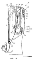
- the head 4 is provided with a needle bar 12, a needle thread take-up lever 13 (see FIG. 15) , a thread tensioning mechanism 14 adjusting a thread tension of the needle thread 11, a threading mechanism 16, and a major part of a thread carrying mechanism 17, and a needle bar threading mechanism 18.
- the needle bar threading mechanism 18 automatically threads a first thread guide 19 provided on a lower end of the needle bar 12 and a second thread guide 20 located near the lower end of the head 4.
- the sewing machine M further includes a moving speed limiting mechanism 21 (a moving speed limiting unit; and see FIG. 9) limiting a moving speed of the thread cassette 10 during attachment of the cassette, a threading operating member 66 (see FIG. 13) corresponding to an operating force transmitting member and an operating force transmitting member for the threading mechanism and a cassette contact 90 (see FIG. 17) corresponding to an operating force transmitting member and an operating force transmitting member for the thread carrying mechanism.
- a moving speed limiting mechanism 21 a moving speed limiting unit; and see FIG. 9
- a threading operating member 66 corresponding to an operating force transmitting member and an operating force transmitting member for the threading mechanism
- a cassette contact 90 see FIG. 17
- the needle thread 11 drawn from the thread cassette 10 attached to the cassette mount 5 is placed on a thread tension shaft (not shown) disposed between a pair of thread tension discs of the thread tensioning mechanism 14.
- the needle thread 11 extending downstream from the thread tension shaft is caught on the needle thread take-up lever 13.
- the threading mechanism 16 and thread carrying mechanism 17 are constructed so as to pass the needle thread 11 through an eye 15a of a sewing needle 15 in synchronization with attachment of the thread cassette 10.
- the thread carryingmechanism 17 As the thread cassette 10 is further attached to the cassette mount 5, the needle thread 11 extending downstream from the needle thread take-up lever 13 is held near the needle eye 15a by the thread carryingmechanism 17 .
- the needle thread 11 is passed through the needle eye 15a and caught on the two thread guides 19 and 20 by the threading mechanism 18.
- the needle thread 11 is set in the sewing machine M so that a sewing operation can be carried out.
- the sewing machine M is constructed so that the needle bar 12 is located at predetermined position above a needle plate 1a before attachment of the thread cassette.
- the bed 1 is provided with a bobbin mount (not shown) to which a bobbin (not shown) is detachably attached. A thread drawn from the bobbin serves as a bobbin thread.
- the bed 1 is further provided with a shuttle mechanism (not shown). When the needle and bobbin threads are set for the sewing operation and a sewing machine motor 9 (not shown) is driven, the needle bar 12 is vertically moved by a needle bar vertically moving mechanism (not shown). The shuttle mechanism is driven in synchronization with the vertical movement of the needle bar 12 so that the needle thread 11 near the needle 15 lowered below a needle plate 1a of the bed 1, whereupon the needle and bobbin threads are entangled to be formed into stitches.
- the thread cassette 10 comprises a cassette body 30 and a lid 31 pivotally mounted on the body.
- the cassette body 30 with the lid 31 defines therein a thread accommodating cavity 33 for accommodating a thread spool 32 serving as a supply of thread.
- a spool pin 34 is mounted on the lid 21.
- the needle thread 11 is set as follows when the preparation for attaching the thread cassette 10 to the cassette mount 5 has been completed. That is, the needle thread 11 extends upward from the thread spool 32 to be drawn out of the thread accommodating cavity 33. The needle thread 11 further extends through a thread path 35 defined between the cassette body 30 and a left end of the lid 31. The needle thread 11 is then put on a first thread guard 36a at a left lower end of the thread cassette 10, further extending rightward thereafter to be put on a second thread guard 36b at a lower end of a partition wall 37 and a third thread guard 36c at a right lower end of the thread cassette 10. The needle thread 11 further extends forward to be put on a fourth thread guard 36d and is then returned to extend leftward. The needle thread 11 is then retained on a thread retainer 38. Furthermore, the needle thread 11 extending leftward is cut by a left blade 39of the thread retainer 38 and the resultant end is put on a fifth thread guard 36e near the blade 39.
- a needle thread take-up lever guide space 40 defined at a right end of the thread cassette 10 extends substantially over the length of the cassette.
- the guide space 40 is open at the rear and the lower portion thereof .
- the thread cassette 10 has a thread tensioning space 41 defined in the central lower end.
- the thread tensioning space 41 is open at the lower portion thereof.
- These spaces 40 and 41 are partitioned by the partition wall 37.
- the right front of the thread cassette 10 is formed with a pair of left and right escape grooves 43 and 44. The escape grooves 43 and 44 prevent a holding member 70 of the thread carrying mechanism 17 from interfering with the right front of the thread cassette 10.
- a thread part 11c between the thread guard 36d and the thread retainer 38 is drawn near the needle eye 15a by the thread carrying mechanism 17 to be held in position (see FIG. 26).
- a cam member 42 which will be described in detail later is provided between the thread guard 36d and the thread retainer 38 for rocking a thread holding member 74 of the thread carrying mechanism 17.
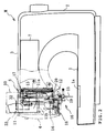
- On the left side of the thread cassette 10 are provided a rack 120 of a moving speed limiting mechanism 21 serving as a moving speed limiting unit and a switching and guiding member 126. The mechanism 21 will be described in detail later.
- the moving speed limiting mechanism 21 comprises the rack 120, a pinion 121 and a rotational resistance applying member 122 (a rotational resistance applying unit).
- the rack 120 is mounted on the thread cassette 10 so as to extend downward.
- the pinion 121 is provided on the machine head 4 so as to be displaced or more specifically rocked between a meshing position where the pinion meshes the rack 120 and a retreat position where the pinion is disengaged from the rack 120.
- the rotational resistance applying member 122 applies rotational resistance to the pinion 121.
- the moving speed limiting mechanism 21 further includes a switching mechanism 123 switching the pinion 121 to the meshing position when the thread cassette 10 is attached to the cassette mount 5 and to the retreat position when the thread cassette 10 is detached from the cassette mount 5.
- the rack 120 extends downward from the vertically middle of the left side of the cassette body 30 and projects leftward.
- the rack 120 has teeth formed on the front thereof.
- the pinion 121 is rotatablymounted on a pinion support plate 124.
- the support plate 124 is further mounted, for rocking motion, on a frame member 14a supporting the thread tensioning shaft of the thread tensioning mechanism 14 with a shaft 124b serving as a rocking axis.
- the pinion support plate 124 includes a right rear end from which a driven pin 124a projects rightward.
- the driven pin 124a is operated by the switching and guiding member 126 so that the pinion 121 is switched from the meshing position to the retreat position.
- the driven pin 124a is received by a receiving member 120a formed on an upper end of the rack 120 when the pinion 121 is switched from the meshing position to the retreat position.
- the pinion 121 is mounted on the rotational resistance applying member 122 which is further mounted on the pinion support plate 124.
- the interior of the rotational resistance applying member 122 is filled with a fluid such as grease.
- the rotational resistance applying member 122 applies rotational resistance to the pinion 121 by means of viscous resistance of the grease.
- the pinion 121 is switched to the meshing position where the pinion meshes the rack 120, when the pinion support plate 124 is rocked rearward, as shown in FIGS. 11C and 11D.
- the pinion support plate 124 is rocked forward, the pinion 121 is switched to the retreat position where the pinion is prevented from meshing the rack 120, as shown in FIG. 11E.
- a switching mechanism 123 comprises a leaf spring 125 (a biasing member) and a switching and guiding member 126.
- the leaf spring 125 biases the pinion 121 from the meshing position toward the retreat position.
- the switching and guiding member 126 is provided on the cassette body 30. When the thread cassette 10 is attached to the cassette mount 5, the pinion 121 is switched against a biasing force of the leaf spring 125 from retreat position to the meshing position.
- the switching and guiding member 126 further guides the rack 120 moved in mesh engagement with the pinion 121.
- the leaf spring 125 has an upper end 125a (a free end) connected to an upper end of the pinion support plate 124 located over the shaft 124b.
- the leaf spring 125 further has a lower end 125b (a fixed end) fixed to the frame member 14a.
- the leaf spring 125 biases the pinion support plate 124 so that the plate 124 stands substantially upright.
- the switching and guiding member 126 is formed integrally on the cassette body 30 so that a portion thereof located in the rear of the rack 120 extends downward.
- the switching and guiding mechanism 126 includes a parallel guide portion 126a and an inclined guide portion 126b.
- the parallel guide portion 126a is located slightly lower than the receiving member 120a of the rack 120 and extends downward in parallel to the rack.
- the inclined guide portion 126b is located below the rack 120 and extends from the lower end of the parallel guide portion 126a so as to be bent obliquely downward.
- a guide groove 127 is formed between the rack 120 and the parallel guide portion 126a. The guide groove 127 guides the driven pin 124a when the thread cassette 10 is detached from the cassette mount 5.
- a guide protrusion 500 (see FIG. 5) is formed on a lower part of the switching and guiding member 126. The guide protrusion 500 adjusts the direction of the cassette body 30 relative to the opening of the cassette mount 5 when the thread cassette 10 is attached to the cassette mount 5.
- the pinion support plate 124 subjected to the biasing force of the leaf spring 125 thereby to stand upright as shown in FIG. 11A is moved upward relative to the thread cassette 10 in the rear of the switching and guiding member 126 while the driven pin 124a is being guided by the inclined guide portion 126b, as shown in FIG. 11B.
- the pinion support plate 124 is rocked rearward against the biasing force of the leaf spring 125, whereupon the pinion 121 is switched to the meshing position where the pinion meshes the rack 120, as shown in FIG. 11C.
- the driven pin 124a once abuts against the receiving portion 120a formed on the upper end of the rack 120 . Subsequently, the pinion support plate 124 is caused to stand upright so that the pinion 121 is departed from the rack 120 to be switched to the retreat position where the pinion is prevented from meshing the rack.
- the pinion 121 is switched to the retreat position upon completion of attachment of the thread cassette 10 to be held at the retreat position by the biasing force of the leaf spring 125 as described above. Accordingly, the driven pin 125 enters the guide groove 127 defined between the rack 120 and the switching and guiding member 126 from the condition as shown in FIG. 12A without mesh engagement of the rack and pinion.
- the thread cassette 10 is then moved upward, the rear of the rack 120 is guided by the driven pin 124a (see FIG. 12B).
- the driven pin 124a is pressed forward against the biasing force of the leaf spring 125 by the inclined guide portion 126b, as shown in FIG. 12C.
- the pinion support plate 124 is then rocked forward as shown in FIG. 12D.
- the driven pin 124a is then disengaged from the inclined guide portion 126b, the biasing force of the leaf spring 125 rocks the pinion support plate 124 rearward, so that the pinion support plate 124 is caused to stand upright.
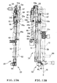
- the threading mechanism 16 comprises a threading shaft 50, a slider guide shaft 51, a slider 52, a hook mechanism 53, a threading shaft driving member 54 and a threading operation member 66.
- the threading shaft 50 and slider guide shaft 51 are provided on the left of the needle bar 12 so as to be vertically moved.
- the slider 52 is fitted with upper ends of the threading shaft 50 and slider guide shaft 51 so as to be vertically moved.
- the hook mechanism 53 is connected to a lower end of the threading shaft 50 so that the needle thread 11 is passed through the needle eye 15a in synchronization with the pivotal movement of the threading shaft 50.
- the threading shaft driving member 54 drives the threading shaft 50 downward in synchronization with attachment of the thread cassette 10.
- the threading operation member 66 is pressed by the thread cassette 10 so that an operating force for operation of the threading mechanism is transmitted to the threading shaft driving member 54.
- the threading shaft 50 and slider guide shaft 51 are mounted on a needle bar base 55 together with the needle bar 12 so that the needle bar 12, needle bar base 55, threading shaft 50 and slider guide shaft 51 are rocked together.
- the needle bar 12 Under the condition immediately before the threading operation (the condition immediately before attachment of the thread cassette 10), the needle bar 12 is located at a position where the needle thread 11 can be passed through the needle eye 15a or more specifically, a predetermined position slightly lower than an uppermost position.
- Two pin members 56a and 56b protrude from an upper end and vertically middle portion of the threading shaft 50.
- the pin member 56b engages a limiting member 13c fixed to the vertically middle portion of the threading shaft 50 when the threading shaft 50 is lowered a predetermined amount.
- the threading shaft 50 is further provided with a coil spring 57 upwardly biasing the threading slider 52.
- the slider guide shaft 51 has an upper half around which a coil spring 58 upwardly biasing the threading slider 52 is provided.
- the threading slider 52 is formed with a cam groove 52a including an upper half straight groove and a lower half spiral groove.
- the threading slider 52 is further provided with a protruding plate 59 protruding upward.
- the protruding plate 59 includes a rear face further including a horizontal face (not shown).
- the hook mechanism 53 includes a threading hook 60 catching the needle thread 11, two guide members 61 and 62 located at both sides of the threading hook 60 respectively, a thread holding wire 90 horizontally extending through the threading hook 60 and guide members 61 and 62, and a hook holding member 64 fixed to the lower end of the threading shaft 50 to hold the threading hook 60, guide members 61 and 62, etc.
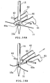
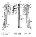
- the threading hook 60 has a distal end formed with hook portion 60a as shown in FIGS. 14A and 14B.
- the hook portion 60a is inserted through the needle eye 15a when the sewing machine M is threaded.
- the needle thread 11 held near the needle eye 15a by the thread carrying mechanism 17 is caught by the threading hook 60 while the hook is guided by the two guide members 61 and 62 disposed at opposite sides thereof.
- the threading shaft driving member 54 is rotatably coupled with the threading operation member 66 provided on the guide shaft 65 so as to be vertically moved.
- the threading shaft driving member 54 is biased clockwise in FIG. 13A by a torsion coil spring 67 .
- the threading operation member 66 is biased upward by a coil spring 68.
- the lower end of the cassette body 30 abuts against the lower end of the threading operation member 66 when the thread cassette 10 is attached to the cassette mount 5.
- the threading operation member 66 is pressed downward against the biasing force of the coil spring 68.
- a driving force transmitting portion 54a is formed on an upper end of the threading shaft driving member 54.
- the driving force transmitting portion 54a abuts the horizontal face of the protruding plate 59 to transmit the driving force at the time of attachment of the thread cassette 10 to the threading slider 52.
- the threading shaft driving member 54 has a lower end formed with a cam portion 54b shutting off transmission of drive force to the threading slider 52.
- the guide shaft 65 has a lower end to which a cam member 69 having an inclined distal cam portion 69a is fixed. The camportion 54b abuts against the distal cam portion 69a when the threading shaft driving member 54 is moved downward a predetermined amount.
- the threading operation by the threading mechanism 16 will now be described.
- an operating force is transmitted from the thread cassette to the threading operation member 66, so that the member 66 is moved downward.
- the threading shaft driving member 54 is driven downward against the biasing force of the coil spring 68 in synchronization with the movement of the threading operation member 66.
- the driving force transmitting portion 54a is brought into contact with the horizontal face of the protruding plate 59 so that the driving force is transmitted to the plate 59.
- the threading shaft 50 and the slider guide shaft 51 are also moved downward.
- the pin member 56a provided on the threading shaft 50 is then moved along the cam groove 52a of the threading slider 52. Accordingly, the downward movement of the threading slider relative to the threading shaft 50 is converted to a rotational movement of the threading shaft 50, whereupon the threading shaft 50 is rotated a predetermined angle.
- the hook mechanism 53 provided on the lower end of the threading shaft 50 is also rotated to the needle 15 side with the shaft 50, the hook portion 60a of the threading hook 60 is passed through the needle eye 15a to catch the needle thread 11, as shown in FIG. 14A.
- the threading shaft driving member 54 is moved downward into a predetermined position and the cam portion 54b abuts the distal cam portion 69a of the cam member 69 when the hook portion 60a has caught the needle thread 11, as shown in FIG. 14A.
- the member 54 is rotated counterclockwise in FIG. 13A by the distal cam portion 69a against the biasing force of the torsion coil spring 67. Since the driving force transmitting portion 54a departs from the horizontal face of the protruding plate 59, the driving force driving the threading shaft 50 downward is not transmitted to the threading slider 52.
- threading shaft 50 is rotated in the opposite direction and returned upward by the biasing force of the coil spring 58.
- the hook mechanism 53 is also rotated in such a direction as to depart from the needle 15. Accordingly, the threading hook 60 which has caught the needle thread 11 is returned through the needle eye 15a, as shown in FIG. 14B, whereupon the threading operation is completed.
- the thread carrying mechanism 17 includes a holding member 70, an interlock transfer mechanism 73, a thread interposing member 74 and a torsion coil spring 75.
- the holding member 70 includes a pair of thread holding portions 71 and 72 capable of holding the needle thread 11 at predetermined intervals.
- the interlock transfer mechanism 73 transfers the thread holding portions 71 and 72 near the needle eye 15a in synchronization with attachment of the thread cassette 10.
- the thread interposing member 74 includes a left thread holding portion 71 for releasably interposing the needle thread 11.
- the torsion coil spring 75 elastically biases the thread interposing member 74 to the thread holding side.
- a cam member 42 is provided on the cassette body 30 of the thread cassette 10 for rocking the thread interposing member 74 temporarily to the releasing side in synchronization with a predetermined stage of a cassette attachment.
- the thread carrying mechanism 17 includes a body frame 76 fixed to the head 4, a moving frame 77 which is guided and supported by the body frame so as to be moved upward and downward and to which the holding member 70 is fixed.
- the moving frame 77 is moved by the interlock transfer mechanism 73.
- the body frame 76 includes a needle thread take-up lever guiding member 78 located at both sides of the vertically rocking path of the needle thread take-up lever 13 and a pair of left and right guide plates 79a and 79b (see FIG. 3) provided on the right side of the guide member 78 and guiding the moving frame 77 verticallymoved.
- the aforesaid guide member 27 guiding the thread cassette 10 in attachment of the cassette is formed integrally on a left portion of the left guide plate 79a.
- the moving frame 77 includes a pair of moving plates 80a and 80b provided between the guide plates 79a and 79b and connected to each other by a plurality of connecting pins.
- the holding member 70 and the thread interposing member 74 will first be described.
- the thread holding portions 71 and 72 of the holding member 70 are connected to each other by a connecting member 81.
- the connecting member 81 has a right end extending horizontally rightward and is fixed via a holding member support 104 to a second wire 101 of the interlock transfer mechanism 73.
- the thread holding portions 71 and 72 are formed with recesses 71a and 72a for catching the needle thread 11 in attachment of the thread cassette 10 respectively.
- the thread interposing member 74 is pivotallymounted on a support shaft 82 furthermounted on the left thread holding member 71.
- a torsion coil spring 75 is provided around the support shaft 82.
- a recess 74a is formed in a front lower end of the thread interposing member 74.
- the recess 74a interposes the needle thread 11 in cooperation with the left thread holding portion 71.
- a driven pin 84 is provided on the lower end of the thread interposing member 74.
- the driven pin 84 is operated by a cam member 42 as will be described later.
- a limiting pin 85 is provided on the upper end of the thread interposing member 74 .
- the upper end of the member 74 is opposed to the driven pin 84 relative to the support shaft 82.
- the limiting pin 85 prevents the thread interposing member 74 from rocking to the thread interposing side over a predetermined range.
- the driven pin 84 projects leftward, whereas the limiting pin 85 projects rightward.
- the interlock transfer mechanism 73 includes a cassette contact 90 made of a synthetic resin and first and second running block mechanisms 91 and 92 .
- the cassette contact 90 comes into contact with the thread cassette 10 during attachment of the cassette thereby to be pressed downward.
- the running block mechanisms 91 and 92 are constructed to move the holding member 70 by an amount of movement four times larger than the movement amount of the cassette contact 90.
- the cassette contact 90 is vertically moved between the paired guide plates 79a and 79b of the body frame 76.
- the cassette contact 90 includes a contact portion 90a formed on a left end thereof so as to project leftward from left guide plate 79a.
- the first running block mechanism 91 includes a pulley 93 which is coupled to the cassette contact 90 so as to be vertically moved with the contact, a first wire 94 wound on the pulley 93 and having an end fixed to the guide plate 79b, and a pulley 95 coupled to the other end of the first wire 94.
- the pulley 93 is enclosed in a pulley accommodating member 96 made of a synthetic resin.
- the pulley accommodating member 96 is vertically moved with the pulley 93 between the guide plates 79a and 79b below the cassette contact.
- a coil spring 97 is provided between the cassette contact 90 and the pulley accommodating member 96 for biasing the cassette contact upward relative to the pulley 93.
- the pulley 93 and the pulley accommodating member 96 are biased upward by a coil spring 98 provided for returning the moving frame 77 upward.
- the coil spring 98 has a lower end connected to the lower end of the left moving plate 80a.
- the first wire 94 has one end fixed to a portion of the guide plate 79b located above the cassette contact 90 and the other end fixed to a pin member 99 connecting upper ends of the paired moving plates 80a and 80b.
- the pin member 99 is supported on the guide plates 79a and 79b so as to be vertically moved along the guide groove 100.
- the pulley 95 is rotatably mounted on the pin member 99. Accordingly, the pulley 95 and moving plates 80a and 80b are vertically moved relative to the guide plates 79a and 79b (body frame 76) while the pin member 99 is guided by the guide groove 100.
- the pulley 93 When the cassette contact 90 is brought into contact with the thread cassette 10 during cassette attachment thereby to be pushed downward, the pulley 93 is also pushed downward with the cassette contact 90. In this case, since the pulley 93 serves as a running block, the pulley 95 and moving frame 77 are moved downward by an amount twice as large as the movement amount of the cassette contact 90.
- the second running block mechanism 92 includes a second wire 101 having both ends fixed to the guide plate 79b and two pulleys 102 and 103 on which the second wire 101 is wound.
- the pulleys 102 and 103 are rotatably supported on the lower and upper ends of the moving plates 80a and 80b respectively.
- the second wire 101 has one end fixed to the upper end of the guide plate 79b and the other end fixed to the lower end of the guide plate 79b while the second wire 101 is wound on the pulleys 102 and 103.
- a holding member support 104 made of a synthetic resin is fixed to a portion of the second wire 101 between the pulleys 102 and 103.
- the connecting member 81 of the holding member 70 is connected to the holding member support 104.
- the holding member support 104 and connecting member 81 are supported between the paired moving plates 80a and 80b so as to be vertically moved along the guide groove 105.
- the two pulleys 102 and 103 are also moved downward with movement of the plates 80a and 80b.
- the pulley 102 acts as a running block. Accordingly, when a portion of the second wire 101 wound on the pulley 102 is pushed downward by the pulley, the second wire 101 is moved downward (leftward as viewed in FIG. 17) from the front (right side as viewed in FIG. 17) of the pulley 102 by an amount twice as large as movement amount of the pulley 102. That is, the holding member 70 connected to the portion of the second wire 101 between the pulleys 102 and 103 is also moved downward and thus, a movement amount of the holding member 70 is four times larger than that of the thread cassette 10.
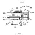
- the cam member 42 is formed integrally on the front of the cassette body 30 so as to project forward as shown in FIGS. 4, 6, 7 and 15.
- the cam member 42 includes a projecting portion 110 projecting forward from the front of the cassette body 30 and a cam formed portion 111 extending rightward from a front end of the projecting portion 110.
- a pin passage 112 is defined between the cam formed portion 111 and the front of the thread cassette 10.
- the driven pin 84 passes through the pin passage 112 relative to the thread cassette 10 during attachment of the cassette.
- a cam face 111a is formed on the rear of the cam formed portion 111.
- the driven pin 84 moves or slides along the cam face 111a during the cassette attachment.
- the cam face 111a includes an upper inclined face expanding rearward as it goes downward and a lower inclined face continuous to a lower end of the upper inclined face and expanding frontward as it goes downward. More specifically, the cam face 111a confronting the front of the thread cassette 10 is formed so as to project rearward. A boundary between the upper and lower inclined faces is bent and the cam face 111a projects rearmost at the bent portion .
- the driven pin 84 passes through the pin passage 112 along the cam face 111a as the thread cassette 10 is moved downward.
- the driven pin 84 is thus operated by the cam member 42 so that the thread interposing member 74 is rocked back and forth.
- the needle thread 11 is interposed between the thread holding portion 71 and the thread interposing member 74.
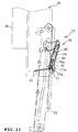
- FIG. 18 shows the condition immediately after the thread cassette 10 has come into contact with the cassette contact 90.
- the thread interposing member 74 is biased to the thread interposing side by the torsion coil spring 75.
- the operating force is transmitted from the thread cassette 10 to the cassette contact 90, so that the contact is moved downward, as shown in FIG. 19.
- the holding member 70 is moved downward in synchronization with the movement of the cassette contact 90. In this case, a movement amount of the holding member 70 is rendered four times larger than that of the thread cassette 10 by the first and second running block mechanisms 91 and 92 in FIG. 17.
- the needle thread 11 is interposed between the recess 71a of the thread holding portion 71 and the recess 74a of the thread interposing portion 74.
- the limiting pin 85 is spaced away upward from the recess 71a and the thread interposing portion 74a.
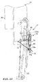
- Themoving frame 77 is further moved downward while the needle thread 11 is interposed, as shown in FIG. 23.
- the needle thread 11 is held near the needle eye 15a by the thread holding portions 71 and 72.
- a hook mechanism 53 of the threading mechanism 16 is rotated clockwise so that the threading hook 60 passes through the needle eye 15a.
- the cassette contact 90 depressed in contact with the lower end of the thread cassette 10 is departed from the cassette when the holding member 70 has been moved near the needle eye 15a.
- the pulley 93 is moved upward by the biasing force of the returning coil spring 98.
- the moving frame 77 and the holding member 70 are moved upward.
- the needle thread 11 held by the thread holding portions 71 and 72 is then caught by the threading hook 60.
- the hook mechanism 53 is returned counterclockwise in FIG. 24, whereupon the needle thread 11 is passed through the needle eye 15a as shown in FIGS. 25 and 26.
- the driven pin 124a When the driven pin 124a relatively reaches the upper end of the switching and guiding member 126, the driven pin 124a is disengaged from the switching and guiding member, as shown in FIG. 11E. The driven pin 124a is then rocked forward by the biasing force of the leaf spring 125 to be once received by the receiving portion 120a. Consequently, the pinion holder plate 124 is slightly rocked forward to stand upright, whereupon the pinion 121 is switched to the retreat position where the pinion is prevented from mesh engagement with the rack 120.
- the operating force for operating threading mechanism 16 and the thread carrying mechanism 17 is transmitted to the threading operating member 66 and the cassette contact 90 when the threading operating member and the cassette contact are pressed by the thread cassette 10. Downwardly moving speeds of the threading operating member 66 and the cassette contact 90 are also limited in the same manner as described above. Accordingly, a suitable operating force is applied to each of the threading mechanism 16 and thread carrying mechanism 17, whereupon these mechanisms are operated at respective suitable operatingspeeds. Consequently, the threading operation and the thread carrying operation can be carried out reliably by the threading mechanism 16 and the thread carrying mechanism 17 respectively.
- the pinion 121 is automatically switched from the meshing position to the retreat position by the switching mechanism 123 in the attachment of the thread cassette 10. Accordingly, the pinion 121 is spaced from the rack 120 when the thread cassette 10 is disengaged from the cassette mount 5. Resistance preventing detachment does not act on the thread cassette 10 as shown in FIGS. 12A to 12E, and the thread cassette can be detached from the cassette mount 5.
- the downwardly moving speed of the thread cassette 10 is limited by the moving speed
- the downwardly moving speed of the thread cassette is limited by the rotational resistance applying member 122 even when the downwardly moving speed of the thread cassette 10 is excessively high, such as when the thread cassette is thrust into the cassette mount 5 at a stroke. Consequently, shock caused in the thread cassette 10 or sewing machine body M1 can be reduced in attachment of the thread cassette. Accordingly, the thread cassette 10 can be prevented from being damaged and the cassette mount 5 can be prevented frombeing broken. Furthermore, any equipment provided in the sewing machine for sewing and sewing preparation can also be prevented from being broken.
- the operating force is transmitted from the thread cassette 10 to the threading operation member 16 and the cassette contact 90. More specifically, the operating force is transmitted from the threading mechanism 16 and the thread carrying mechanism 17 to the threading member 66 and the cassette contact 90. Since the moving speed of the thread cassette 10 is limited by the moving speed limiting mechanism 21, the downwardly moving speeds of the threading operation member 66 and cassette contact 90 are also limited. Consequently, the threading mechanism 16 and the thread carrying mechanism 17 can be operated at suitable speeds respectively, and accordingly, the threading operation and the thread carrying operation can be carried out reliably.
- the switching mechanism 123 switches the pinion 121 to the meshing position where the pinion meshes the rack 120. Consequently, the moving speed of the thread cassette 10 can be limited reliably in the attachment to the cassette mount 5. Furthermore, when the thread cassette 10 is detached from the cassette mount 5, the switching mechanism 123 switches the pinion 121 to the retreat position where the pinion is prevented from mesh engagement with the rack 120. Consequently, the thread cassette 10 can be detached from the cassette mount 5 smoothly since no resistance preventing detachment is applied to the thread cassette.
- the driven pin 124a is reliably abutted against the rear of the inclined guide portion 126b by the elastic biasing force of the leaf spring 125 during attachment of the thread cassette 10. Consequently, since mesh engagement is reliably maintained between the pinion 121 and rack 120, the downwardly moving speed of the thread cassette 10 can reliably be limited.
- the present invention may be applied to sewing machines constructed so that an operating force for operating the threading mechanism 16 or the thread carrying mechanism 16 is supplied by a manually operated operating lever. In this case, even when the operating lever is thrust at a stroke, the downwardly moving speed of the operating force transmitting member can be limited.
- the invention may also be applied to sewing machines provided with no threading mechanism 16 and no thread carrying mechanism 17.
- shock resulting from attachment of the thread cassette is reduced by limiting the downwardly moving speed of the thread cassette by the moving speed limiting mechanism 21. Consequently, components mounted around the cassette mount 5 can be prevented from being broken.
- the moving speed limiting mechanism 21 applies rotational resistance to the pinion 121 meshing the rack 120 thereby to limit the moving speed of the thread cassette 10 .
- rubber or the like may be brought into direct contact with the thread cassette 10 so that frictional resistance is applied to the thread cassette, instead.
- a biasing member such as a coil spring may be provided for biasing the thread cassette 10 upward.
- the liquid of the rotational resistance applying unit may be another liquid having a relatively higher viscosity, instead of grease.
- a suitable fluid or a gas may be employed instead of the liquid.
- an air damper or the like may be used as the rotational resistance applying unit.
- the supply of thread accommodated in the thread cassette may be a thread spool, bobbin or mere lamp of thread, instead, and thus, various types of thread supplymaybe used. Furthermore, the thread spool or lamp of thread may merely be mounted on a spool pin while being exposed.
- the user thrusts the thread cassette 10 into the cassette mount 5.
- Another driving means such as rubber rollers or an electric motor may be provided for automatically attaching the thread cassette.
- the driving means may be used to drive the thread carrying mechanism 17 or the threading mechanism 18.
- the pinion 121 is directly connected to the rotational resistance applying unit 122 in the foregoing embodiment.
- the pinion 121 may be connected via a reduction mechanism for reducing a rotational speed of the pinion 121 to the rotational resistance applying unit 122, instead.
- the predetermined rotational resistance can be applied to the pinion 121 by the rotational resistance applying unit 122 since the rotational speed of the pinion 121 is reduced by the reduction mechanism.
- the moving speed limiting mechanism 21 limits the moving speeds of the threading operation member 66 and cassette contact 90 so that the moving speeds do not exceed predetermined values at which the threading mechanism 16 and the thread carrying mechanism 17 can be operated stably.
- the moving speed limiting mechanism 21 may be constructed so that a speed of the operating force applying member is not reduced to or below a predetermined speed, instead. In this case, a predetermined speed of the operating force transmitting member can be maintained while an attaching efficiency of the thread cassette 10 can be improved.
Landscapes
- Engineering & Computer Science (AREA)
- Textile Engineering (AREA)
- Sewing Machines And Sewing (AREA)
Abstract
Description
Claims (11)
- A sewing machine comprising:a sewing machine body provided with a cassette mount;a thread cassette having a supply of thread and detachably attached to the cassette mount; anda moving speed limiting unit limiting a moving speed of the thread cassette when the thread cassette is attached to the cassette mount.
- A sewing machine according to claim 1, wherein the moving speed limiting unit includes a rack provided on the thread cassette so as to extend in a predetermined direction, a pinion provided on the sewing machine body so as to mesh the rack, and a rotational resistance applying unit applying rotational resistance to the pinion.
- A sewing machine according to claim 2, wherein the pinion is displaced between a meshing position where the pinion meshes the rack and a retreat position where the pinion is disengaged from the rack, and the moving speed limiting unit includes a switching mechanism switching the pinion to the meshing position when the thread cassette is attached to the cassette mount and to the retreat position when the thread cassette is detached from the cassette mount.
- A sewing machine according to claim 3, wherein the switching mechanism includes a biasing member biasing the pinion to the retreat position, a switching guide member provided on the thread cassette to switch the pinion from the retreat position to the meshing position against a biasing force of the biasing member when the thread cassette is attached to the cassette mount and further to guide the rack.
- A sewing machine according to one of claims 1 to 4, further comprising:a threading mechanism passing a thread through an eye of a sewing needle;a first operating force transmitting member moved when receiving an operating force transmitted from the thread cassette during attachment of the thread cassette, thereby operating the threading mechanism by means of movement thereof;a thread carrying mechanism carrying the thread near the needle eye in order that the thread may be passed through the needle eye; anda second operating force transmitting member moved when receiving an operating force transmitted from the thread cassette during attachment of the thread cassette, thereby operating the thread carrying mechanism.
- A sewing machine comprising:a sewing machine body provided with a cassette mount;a threading mechanism passing a thread through an eye of a sewing needle;an operating force transmitting member moved when an operating force is transmitted from the thread cassette thereto during attachment of the thread cassette, thereby operating the threading mechanism by means of movement thereof; anda moving speed limiting unit limiting a moving speed of the operating force transmitting member.
- A sewing machine comprising:a sewing machine body provided with a cassette mount;a thread carrying mechanism carrying a thread near an eye of a sewing needle in order that the thread may be passed through the needle eye;an operating force transmitting member moved when an operating force is transmitted from outside the thread carrying mechanism thereto, thereby operating the thread carrying mechanism by means of movement thereof; anda moving speed limiting unit limiting a moving speed of the operating force transmitting member.
- A thread cassette comprising:a cassette body having a supply of thread and detachably attached to a cassette mount provided in a sewing machine; anda moving speed limiting unit limiting a moving speed of the thread cassette when the thread cassette is attached to the cassette mount.
- A thread cassette according to claim 8, wherein the moving speed limiting unit includes:a rack provided on the cassette body;a pinion provided on the sewing machine body so as to mesh the rack;a rotational resistance applying unit applying rotational resistance to the pinion; anda switching mechanism switching the pinion so that the pinion meshes the rack and the rack is guided when the thread cassette is attached to the cassette mount and so that the pinion is prevented from meshing the rack when the thread cassette is detached from the cassette mount.
- A thread cassette according to claim 9, wherein the rotational resistance applying unit uses a liquid to apply the rotational resistance.
- A thread cassette according to claim 9, wherein the rotational resistance applying unit uses a gas to apply the rotational resistance.
Applications Claiming Priority (2)
| Application Number | Priority Date | Filing Date | Title |
|---|---|---|---|
| JP2002264499A JP3960175B2 (en) | 2002-09-10 | 2002-09-10 | Sewing machine and thread cassette attached to this sewing machine |
| JP2002264499 | 2002-09-10 |
Publications (3)
| Publication Number | Publication Date |
|---|---|
| EP1398405A2 true EP1398405A2 (en) | 2004-03-17 |
| EP1398405A3 EP1398405A3 (en) | 2005-05-25 |
| EP1398405B1 EP1398405B1 (en) | 2011-04-06 |
Family
ID=31884760
Family Applications (1)
| Application Number | Title | Priority Date | Filing Date |
|---|---|---|---|
| EP03020608A Expired - Lifetime EP1398405B1 (en) | 2002-09-10 | 2003-09-10 | Sewing machine and tread cassette attached thereto |
Country Status (5)
| Country | Link |
|---|---|
| US (1) | US7100524B2 (en) |
| EP (1) | EP1398405B1 (en) |
| JP (1) | JP3960175B2 (en) |
| CN (1) | CN100436693C (en) |
| DE (1) | DE60336615D1 (en) |
Families Citing this family (2)
| Publication number | Priority date | Publication date | Assignee | Title |
|---|---|---|---|---|
| US9032889B2 (en) * | 2011-03-04 | 2015-05-19 | Brother International Corporation | Cartridge selection mechanism for a sewing machine |
| CN103710910A (en) * | 2013-12-30 | 2014-04-09 | 吴江市菀坪铭正缝纫机零件厂 | Detachable sewing machine containing box |
Family Cites Families (24)
| Publication number | Priority date | Publication date | Assignee | Title |
|---|---|---|---|---|
| US2900941A (en) * | 1956-03-19 | 1959-08-25 | Singer Mfg Co | Spool holders for sewing machines |
| US3749039A (en) * | 1972-10-24 | 1973-07-31 | Singer Co | Cassette threading arrangement in sewing machines |
| US4100867A (en) * | 1977-01-21 | 1978-07-18 | Mattel, Inc. | Sewing machine |
| US4183313A (en) * | 1978-12-14 | 1980-01-15 | The Singer Company | Sewing machine cassette threading system |
| JPS5761756A (en) * | 1980-09-29 | 1982-04-14 | Aisin Seiki | Magnetic tape for embroidering machine |
| JPS6041751Y2 (en) * | 1980-11-27 | 1985-12-19 | 株式会社ニフコ | door damper device |
| CH674859A5 (en) * | 1988-05-09 | 1990-07-31 | Mefina Sa | |
| CH677509A5 (en) * | 1988-11-30 | 1991-05-31 | Mefina Sa | |
| JP3275352B2 (en) * | 1992-03-31 | 2002-04-15 | アイシン精機株式会社 | Sewing machine |
| JP3640400B2 (en) | 1992-12-23 | 2005-04-20 | 株式会社ニフコ | Car article storage device |
| JP3304030B2 (en) * | 1995-07-24 | 2002-07-22 | 東北パイオニア株式会社 | Loading / ejecting mechanism of tape recorder |
| JP2000145272A (en) | 1998-11-09 | 2000-05-26 | Osaka Kanagu Kk | Speed reducer for self-closing device of sliding door |
| JP2000235749A (en) * | 1999-02-16 | 2000-08-29 | Sanyo Electric Co Ltd | Video cassette recorder |
| JP2001040569A (en) | 1999-05-25 | 2001-02-13 | Miyamoto Kk | Device for feeding or recovering yarn in embroidering machine |
| US6814014B2 (en) * | 2000-07-03 | 2004-11-09 | Brother Kogyo Kabushiki Kaisha | Sewing apparatus and sewing cartridge |
| JP2002095882A (en) * | 2000-09-26 | 2002-04-02 | Brother Ind Ltd | Needle thread cassette and needle thread changing device |
| JP2002189517A (en) | 2000-12-21 | 2002-07-05 | Mitsubishi Heavy Ind Ltd | System for monitoring compressor station for pipe line |
| WO2002053822A1 (en) * | 2000-12-27 | 2002-07-11 | Brother Kogyo Kabushiki Kaisha | Sewing machine |
| JP2002191886A (en) | 2000-12-27 | 2002-07-10 | Brother Ind Ltd | sewing machine |
| JP3797326B2 (en) * | 2000-12-27 | 2006-07-19 | ブラザー工業株式会社 | Sewing machine with upper thread cassette and upper thread cassette |
| JP2002191884A (en) * | 2000-12-27 | 2002-07-10 | Brother Ind Ltd | sewing machine |
| JP3881860B2 (en) * | 2001-10-12 | 2007-02-14 | Juki株式会社 | Thread winding method |
| JP3800137B2 (en) * | 2002-06-28 | 2006-07-26 | ブラザー工業株式会社 | Sewing device and sewing device program |
| USD499751S1 (en) * | 2002-11-07 | 2004-12-14 | Brother Industries, Ltd. | Thread cassette for sewing machine |
-
2002
- 2002-09-10 JP JP2002264499A patent/JP3960175B2/en not_active Expired - Fee Related
-
2003
- 2003-09-08 US US10/656,338 patent/US7100524B2/en not_active Expired - Fee Related
- 2003-09-10 CN CNB031272924A patent/CN100436693C/en not_active Expired - Fee Related
- 2003-09-10 DE DE60336615T patent/DE60336615D1/en not_active Expired - Lifetime
- 2003-09-10 EP EP03020608A patent/EP1398405B1/en not_active Expired - Lifetime
Also Published As
| Publication number | Publication date |
|---|---|
| US20040173131A1 (en) | 2004-09-09 |
| EP1398405B1 (en) | 2011-04-06 |
| DE60336615D1 (en) | 2011-05-19 |
| US7100524B2 (en) | 2006-09-05 |
| CN100436693C (en) | 2008-11-26 |
| EP1398405A3 (en) | 2005-05-25 |
| JP2004097555A (en) | 2004-04-02 |
| JP3960175B2 (en) | 2007-08-15 |
| CN1495314A (en) | 2004-05-12 |
Similar Documents
| Publication | Publication Date | Title |
|---|---|---|
| JPH11333182A (en) | Sewing machine threading device | |
| EP1398405B1 (en) | Sewing machine and tread cassette attached thereto | |
| US6957617B2 (en) | Thread guide threading apparatus and sewing machine provided therewith | |
| US6814016B2 (en) | Sewing machine | |
| US6779470B2 (en) | Sewing apparatus and needle bar position control program therefor | |
| US6880473B2 (en) | Thread holding mechanism and sewing machine provided therewith | |
| US6959656B2 (en) | Threading apparatus for sewing machine | |
| JPWO2002053821A1 (en) | Sewing machine with needle thread cassette and needle thread cassette | |
| US7178473B2 (en) | Sewing machine with automatic threading apparatus | |
| WO2002053822A1 (en) | Sewing machine | |
| JP3797292B2 (en) | Yarn hooking device for yarn guide and sewing machine equipped with this yarn hooking device | |
| JP3797291B2 (en) | Yarn hooking device for needle bar thread guide and sewing machine equipped with this yarn hooking device | |
| US6860212B2 (en) | Threading apparatus for sewing machine | |
| US6776113B2 (en) | Sewing machine with thread tension control function and thread tension control program therefor | |
| US6755140B2 (en) | Sewing apparatus | |
| AU619009B2 (en) | Overlock sewing machine with a looper-thread guide mechanism | |
| US6883448B2 (en) | Sewing apparatus and informing control program therefor | |
| JP2004065321A (en) | sewing machine | |
| JP2006014795A (en) | sewing machine | |
| JP3729409B2 (en) | sewing machine | |
| JP2002325989A (en) | Thread cassette | |
| JP2002355478A (en) | Sewing machine with thread winding function | |
| JP2002191882A (en) | Upper thread cassette |
Legal Events
| Date | Code | Title | Description |
|---|---|---|---|
| PUAI | Public reference made under article 153(3) epc to a published international application that has entered the european phase |
Free format text: ORIGINAL CODE: 0009012 |
|
| AK | Designated contracting states |
Kind code of ref document: A2 Designated state(s): AT BE BG CH CY CZ DE DK EE ES FI FR GB GR HU IE IT LI LU MC NL PT RO SE SI SK TR |
|
| AX | Request for extension of the european patent |
Extension state: AL LT LV MK |
|
| PUAL | Search report despatched |
Free format text: ORIGINAL CODE: 0009013 |
|
| AK | Designated contracting states |
Kind code of ref document: A3 Designated state(s): AT BE BG CH CY CZ DE DK EE ES FI FR GB GR HU IE IT LI LU MC NL PT RO SE SI SK TR |
|
| AX | Request for extension of the european patent |
Extension state: AL LT LV MK |
|
| 17P | Request for examination filed |
Effective date: 20050622 |
|
| AKX | Designation fees paid |
Designated state(s): DE FR GB |
|
| 17Q | First examination report despatched |
Effective date: 20051223 |
|
| GRAP | Despatch of communication of intention to grant a patent |
Free format text: ORIGINAL CODE: EPIDOSNIGR1 |
|
| GRAS | Grant fee paid |
Free format text: ORIGINAL CODE: EPIDOSNIGR3 |
|
| GRAA | (expected) grant |
Free format text: ORIGINAL CODE: 0009210 |
|
| AK | Designated contracting states |
Kind code of ref document: B1 Designated state(s): DE FR GB |
|
| REG | Reference to a national code |
Ref country code: GB Ref legal event code: FG4D |
|
| REF | Corresponds to: |
Ref document number: 60336615 Country of ref document: DE Date of ref document: 20110519 Kind code of ref document: P |
|
| REG | Reference to a national code |
Ref country code: DE Ref legal event code: R096 Ref document number: 60336615 Country of ref document: DE Effective date: 20110519 |
|
| PGFP | Annual fee paid to national office [announced via postgrant information from national office to epo] |
Ref country code: GB Payment date: 20110826 Year of fee payment: 9 |
|
| PLBE | No opposition filed within time limit |
Free format text: ORIGINAL CODE: 0009261 |
|
| STAA | Information on the status of an ep patent application or granted ep patent |
Free format text: STATUS: NO OPPOSITION FILED WITHIN TIME LIMIT |
|
| 26N | No opposition filed |
Effective date: 20120110 |
|
| REG | Reference to a national code |
Ref country code: DE Ref legal event code: R097 Ref document number: 60336615 Country of ref document: DE Effective date: 20120110 |
|
| REG | Reference to a national code |
Ref country code: FR Ref legal event code: ST Effective date: 20120531 |
|
| PG25 | Lapsed in a contracting state [announced via postgrant information from national office to epo] |
Ref country code: FR Free format text: LAPSE BECAUSE OF NON-PAYMENT OF DUE FEES Effective date: 20110930 |
|
| GBPC | Gb: european patent ceased through non-payment of renewal fee |
Effective date: 20120910 |
|
| REG | Reference to a national code |
Ref country code: DE Ref legal event code: R119 Ref document number: 60336615 Country of ref document: DE Effective date: 20130403 |
|
| PG25 | Lapsed in a contracting state [announced via postgrant information from national office to epo] |
Ref country code: DE Free format text: LAPSE BECAUSE OF NON-PAYMENT OF DUE FEES Effective date: 20130403 Ref country code: GB Free format text: LAPSE BECAUSE OF NON-PAYMENT OF DUE FEES Effective date: 20120910 |