EP1398185A1 - Anhängekupplung - Google Patents
Anhängekupplung Download PDFInfo
- Publication number
- EP1398185A1 EP1398185A1 EP02020214A EP02020214A EP1398185A1 EP 1398185 A1 EP1398185 A1 EP 1398185A1 EP 02020214 A EP02020214 A EP 02020214A EP 02020214 A EP02020214 A EP 02020214A EP 1398185 A1 EP1398185 A1 EP 1398185A1
- Authority
- EP
- European Patent Office
- Prior art keywords
- coupling
- cone
- bearing
- ring
- coupling according
- Prior art date
- Legal status (The legal status is an assumption and is not a legal conclusion. Google has not performed a legal analysis and makes no representation as to the accuracy of the status listed.)
- Granted
Links
Images


Classifications
-
- B—PERFORMING OPERATIONS; TRANSPORTING
- B60—VEHICLES IN GENERAL
- B60D—VEHICLE CONNECTIONS
- B60D1/00—Traction couplings; Hitches; Draw-gear; Towing devices
-
- B—PERFORMING OPERATIONS; TRANSPORTING
- B60—VEHICLES IN GENERAL
- B60D—VEHICLE CONNECTIONS
- B60D1/00—Traction couplings; Hitches; Draw-gear; Towing devices
- B60D1/48—Traction couplings; Hitches; Draw-gear; Towing devices characterised by the mounting
- B60D1/54—Traction couplings; Hitches; Draw-gear; Towing devices characterised by the mounting collapsible or retractable when not in use, e.g. hide-away hitches
- B60D2001/542—Traction couplings; Hitches; Draw-gear; Towing devices characterised by the mounting collapsible or retractable when not in use, e.g. hide-away hitches characterised by the number of pivot axes
- B60D2001/548—Three pivot axes
Definitions
- the invention relates to a trailer coupling with a Coupling mouth and an insertable into the coupling mouth Coupling body.
- Trailer couplings are in different embodiments known.
- pin-type towbars in which a coupling pin between the open position and Closed position only linearly adjustable and non-rotatable is led.
- a further provided lifting mechanism is used at the same time to lock the coupling pin in both Positions, with the coupling pin in the closed position thanks to a form-locked knee joint mechanism is locked.
- the from the coupled towing eye against the Coupling bolts generated torques directly on the Transfer lifting mechanism so that the lifting mechanism torsional stresses.
- shear forces generated by the towing eye the coupling pin directly onto the lifting mechanism transmitted so that the lifting mechanism not only torsional stresses, but is also subject to shear stresses. This leads to considerable signs of wear and tear to shorten the lifespan.
- the invention has for its object a trailer coupling the embodiment described above create that increased in a cost-saving manner by Functional reliability and low wear distinguishes, furthermore for heavy-duty attachments, especially for so-called deep attachments is just as suitable as for rigid drawbar trailers but also for commercial vehicles, vehicles of the Agriculture or forestry, self-propelled machinery and car transporters.
- the invention solves this problem with a generic one Trailer coupling in that the coupling body and that Coupling mouth with the formation of a cone coupling corresponding conicity that the Coupling body in the coupling mouth in a coupled state around the main cone axis running in the coupling direction is rotatably mounted and that the cone coupling in one Bearing housing around an orthogonal to the main cone axis Vertical axis is pivotally mounted.
- the invention have the consequence that a Coupling system is realized, which is a backlash-free Coupling with great angular mobility allowed. This angular mobility is controlled by a turnstile formed with mutually perpendicular axes of rotation.
- the vertical axis which is the lateral pivoting the cone coupling allows up to more than 90 °, as well as for the main cone axis intersecting the vertical axis and a pivoting of the cone coupling around this main cone axis allowed.
- the invention is also on the clutch body on the drawbar side a connecting flange with interposition a pivot bearing connected, the Swivel bearing one to the main cone axis and vertical axis forms an orthogonal horizontal axis. That way a turnstile with three mutually perpendicular axes of rotation realized, the horizontal axis a Aufund Movement of the coupling body and consequently the entire cone coupling.
- the cone coupling according to the invention can intersect all axes of rotation, or even one have a predetermined distance from each other.
- the cone coupling according to the invention the free movement for example a drawbar in the room within relative large angular ranges with clutch free of play.
- the angular mobility the cone coupling according to the invention thanks to the implemented turnstile even while driving guaranteed. In fact, it becomes a gimbal Joint realized after coupling. From the game-free Coupling also results in freedom from wear or at least largely wear-free.
- the coupling body expediently a coupling cone with a conical Cover cap with rounding on the front.
- This cover cap which is the insertion of the coupling body into the Clutch mouth relieved, but actually Coupling process practically no longer after coupling participates, consists of rigid plastic or metal, for example brass.
- the pivot bearing preferably has on the drawbar side the bearing cheeks and on the coupling side Bearing journal on which the coupling cone and the cover cap are fixed.
- the bearing collar and the journal are in the coupling cone with the interposition of bearing bushes pivoted about the main cone axis.
- the cover cap can also be attached to the bearing journal be rotated with a given movement game engages in the coupling mouth.
- the coupling cone is all-round Locking groove for retracting and extending the Coupling cone surrounding and radially adjustable Has closure segments.
- the in the locking groove Retracted locking segments lock the coupling cone after the coupling process in the coupling mouth.
- the Locking groove and the locking segments are included Corresponding conicity trained to this extent a backlash-free and therefore wear-free intervention guarantee. In addition, it is flawless Position the coupling body in the coupling mouth ensured.
- the coupling cone is in coupled Position according to the invention of a cone ring as a component of the coupling mouth surrounded without play, with the front on the cone ring a guide ring with radial Guide recesses for the radially movable wear elements is attached.
- the cone ring points to itself opposite sides on vertical trunnions, the with the formation of the vertical axis in corresponding pin receptacles in the bearing housing with the interposition of Bearing bushes are rotatably mounted.
- the guide ring is with the locking segments a control ring for the front Closure segments assigned, being in the closure segments attached control pin in under radius increase or decrease oblique control grooves of the around its Central axis rotatably mounted control ring intervention. Hence results from a rotational movement a radial reciprocation of the control ring the locking segments in the associated guide ring.
- the Control ring has a radial from the coupling mouth cantilevered operating lever.
- the Guide ring with the locking elements and the control ring between the cone ring and a cover with an inner cone as arranged another component of the coupling mouth wherein the cover is attached to the front of the cone ring and its inner cone has the same conicity as the inner cone of the cone ring, ie with the conicity of the cone ring flees.
- This cover can be a guide recess for the operating lever of the control ring.
- the invention further recommends that in the lid and on the control ring a trigger mechanism acting on the control ring is arranged, which is the control ring for a Rotary movement releases or as a safety mechanism locked. Only after the control ring has been released by the The trigger mechanism ensures the springs Rotation of the control ring by a predetermined angle of rotation.
- the trigger mechanism has a on or in the lid against a return spring in Coupling direction pivoted release lever, that of the coupling body entering the coupling mouth or coupling cone is pivoted and onto one pivotable on the cover in the ring plane of the control ring stored locking lever works, the locking lever a Locking recess for snapping one onto the control ring attached locking cam and this after actuation released by the release lever.
- the bearing housing is open as a U-shaped on the drawbar side Housing with a U-base that can be connected on the tractor and .
- the U-legs spanning the cone coupling trained in which the pin receptacles for the Bearing journals are located on the cone ring.
- this middle spring on a bearing pin of the cone ring is connected.
- the cone coupling according to the invention is a new clutch system, which ensures a clutch without play allows high angular mobility at the same time. From the Backlash also results in freedom from wear or at least largely wear-free. It is about with the cone coupling around a closed system small dimensions within that for a 50s Bolt standard coupling specified dimensions. Furthermore can the cone coupling according to the invention technically and economically interesting applications for rigid drawbar trailers Find. The drawbars of such rigid drawbar trailers can then be used as stable beams with box girder profiles be trained. But also applications for everyone Heavy duty attachments and especially for deep ones Attachments are possible. This also applies to commercial vehicles as for agricultural or forestry vehicles, self-driving Working machines, car transporters, etc.
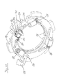
- FIG. 1 there is a trailer coupling with a Coupling mouth 1 and an insertable into the coupling mouth 1 Coupling body 2 shown.
- the clutch body 2 and the coupling mouth 1 are forming a cone coupling with a corresponding conicity.
- the Coupling body 2 is coupled in coupling mouth 1 Condition around the main cone axis running in the longitudinal direction of the coupling K rotatably mounted.
- the cone coupling is in a bearing housing 3 about an orthogonal to the main cone axis K Vertical axis V pivotally mounted.
- To the Coupling body 2 is a connecting flange on the drawbar side 4 with the interposition of a swivel bearing 5 connected.
- the pivot bearing 5 forms a to the main cone axis K and vertical axis V orthogonal horizontal axis H. Furthermore, the pivot bearing 5 has two distanced Bearing cheeks 6, between which a bearing eye 7 on the Connecting flange 4 by means of a bearing pin 8 below Interposition of bearing bushes 9 about the horizontal axis H is pivotally mounted.
- the coupling body 2 has a coupling cone 10 a conical cover cap 11 with a rounded face on.
- the cover cap 11 is made of rigid plastic.
- the pivot bearing 5 has the bearing cheeks on the drawbar side 6 and on the coupling side a bearing collar 12 with a bearing journal 13 on which the coupling cone 10 and Cover cap 11 are fixed.
- the camp 12 and the bearing journal 13 are in the coupling cone 10 with the interposition of bearing bushes 16 about the main cone axis K rotatably mounted.
- the coupling cone 10 has a circumferential locking groove 17 for retracting and extending the coupling cone 10 surrounding and radially adjustable closure segments 18 on. These closure segments 18 are used to lock the in the coupling mouth 1 retracted coupling cone 10 in coupled position.
- the locking groove 17 and the Closure segments 18 are of a corresponding conicity trained to have a backlash-free engagement and consequently proper positioning of the coupling cone 10 in to ensure coupled position.
- the clutch cone 10 is in the coupled position of a cone ring 19 as Part of the coupling mouth 1 surrounded without play.
- To the Cone ring 19 is a guide ring 20 on the face radial guide recesses 21 for the radially movable Closure elements 18 attached.
- the cone ring 19 has vertical bearing journal 22 on opposite sides on, forming the vertical axis V in corresponding Pin receptacles 23 in the bearing housing 3 below Interposition of bearing bushes 24 rotatably mounted are.
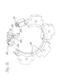
- the guide ring 20 with the wear segments 18 is a control ring 25 for the closure segments 18 assigned.
- In the closure segments 18 are Control pin 26 attached in the under increasing radius or - decrease oblique control grooves 27 of his Central axis rotatably mounted control ring 25 intervene. Rotation of the control ring 25 thus leads to a reciprocating movement of the closure segments 18 just in the closed position or open position.
- the Control ring 25 has a radial from the coupling mouth 1 projecting actuating lever 28 on which the Control ring 25 can be rotated.
- the Guide ring 20 with the closure elements 18 and Control ring 25 are between the cone ring 19 and one Cover 29 with inner cone as a further part of Coupling mouth 1 arranged.
- the cover 29 is on the end face attached to the cone ring 19 and its inner cone has the same conicity as the inner cone of the cone ring 19 on, so that there is an aligned conicity. in the Otherwise, the cover 29 has a guide recess 30 for the actuating lever 28 emerging to the outside.
- control ring 25 On the control ring 25 are distributed over its circumference and in the circumferential direction acting springs 31 arranged are supported on the cover 29 with a predetermined voltage and can set the control ring 25 in rotary motion.
- Cover 29 and on the control ring 25 is on the control ring 25 acting trigger mechanism arranged, which the control ring 25 for a rotational movement over the Actuating lever 28 or via the attacking springs 31 releases or locked as a safety mechanism.
- the trigger mechanism has one on or in the cover 29 pivotable against a return spring 32 in the coupling direction stored trigger lever 33, which from the in Coupling mouth 1 retracting coupling body 2 or Coupling cone 10 is pivoted and on one at the Cover 29 pivoted in the ring plane of the control ring 25 stored locking lever 34 operates, the locking lever 34 a locking recess 35 for locking one on the control ring 25 attached locking cam 36.
- the release lever 33 actuated by the clutch cone 10 and the locking lever 34 depressed with the release of the locking cam 36.
- the control ring 25 is due to its circumferential spring action rotated by a predetermined angle and has transferred the closure segments 18 into the closed position (see Fig. 10).
- a compression spring 37 pushable actuating pin 38 stored in the extended position when swiveling the release lever 33 to a button 39 of the locking lever 34 works in the pivoting direction of the locking lever.
- the locking lever 34 is acted upon by a return spring 40.
- the bearing housing 3 is a U-shaped drawbar side open housing with a connectable on the tractor side U-base 41 and U-legs spanning the cone coupling 42 formed in which the pin receptacles 23 for the bearing pins 22 are located on the cone ring 19.
- On the an upper U-leg 42 is a middle spring 43 for Center the coupling jaw 1 in the middle position arranged.
- This middle spring 43 is on the associated bearing journal 22 of the conical ring 19 connected.
- the cone coupling is opened by Actuation of the control ring 25 by means of the actuation lever 28 in the circumferential direction.
- the closure segments 18 raised and release the coupling cone 10.
Landscapes
- Engineering & Computer Science (AREA)
- Transportation (AREA)
- Mechanical Engineering (AREA)
- Mechanical Operated Clutches (AREA)
- Massaging Devices (AREA)
- Percussion Or Vibration Massage (AREA)
- Dental Tools And Instruments Or Auxiliary Dental Instruments (AREA)
Abstract
Description
- Fig. 1
- Eine erfindungsgemäße Anhängekupplung in perspektivischer Darstellung und entkuppeltem Zustand,
- Fig. 2
- den Gegenstand nach Fig. 1 im Zuge eines Kupplungsvorganges,
- Fig. 3
- den Gegenstand nach Fig. 1 nach Abschluss des Kupplungsvorganges und folglich bei in das Kupplungsmaul eingeführtem Kupplungskörper,
- Fig. 4
- das Kupplungsmaul für den Gegenstand nach Fig. 1 in perspektivischer Darstellung,
- Fig. 5
- einen Vertikalschnitt durch eine erfindungsgemäße Anhängekupplung,
- Fig. 6
- einen Horizontalschnitt durch den Gegenstand nach Fig. 5,
- Fig. 7
- einen Querschnitt AA durch den Gegenstand nach Fig. 6 im Bereich des Führungsringes mit seinen in Schließstellung befindlichen Verschlusssegmenten,
- Fig. 8
- einen Querschnitt BB durch den Gegenstand nach Fig. 6 im Bereich des Steuerrings mit seinen Steuernuten,
- Fig. 9
- den Steuerring für den Gegenstand nach Fig. 1 in perspektivischer Darstellung bei gedrücktem Auslösehebel und in Offenstellung befindlichen Verschlusssegmenten,
- Fig. 10
- den Gegenstand nach Fig. 9 bei gedrücktem Auslösehebel und in Schließstellung befindlichen Verschlusssegmenten,
- Fig. 11
- den Gegenstand nach Fig. 9 ohne Auslösehebel,
- Fig. 12
- Auslösehebel und Rasthebel für den Gegenstand nach Fig. 9 bei entlastetem Auslösehebel und
- Fig. 13
- den Gegenstand nach Fig. 1 in Explosivdarstellung.
Claims (23)
- Anhängekupplung mit einem Kupplungsmaul und einem in das Kupplungsmaul einführbaren Kupplungskörper, dadurch gekennzeichnet, dass der Kupplungskörper (2) und das Kupplungsmaul (1) unter Bildung einer Konuskupplung mit korrespondierender Konizität ausgebildet sind, dass der Kupplungskörper (2) in dem Kupplungsmaul (1) in gekuppeltem Zustand um die in Kupplungslängsrichtung verlaufende Konushauptachse (K) drehbar gelagert ist und dass die Konuskupplung in einem Lagergehäuse (3) um eine zur Konushauptachse (K) orthogonale Vertikalachse (V) schwenkbar gelagert ist.
- Anhängekupplung nach Anspruch 1, dadurch gekennzeichnet, dass an dem Kupplungskörper (2) ein Verbindungsflansch (4) unter Zwischenschaltung eines Schwenklagers (5) angeschlossen ist und das Schwenklager (5) eine zur Konushauptachse (K) orthogonale Horizontalachse (H) bildet.
- Anhängekupplung nach Anspruch 1 oder 2, dadurch gekennzeichnet, dass das Schwenklager (5) zwei Lagerwangen (6) aufweist zwischen denen ein Lagerauge (7) an dem Verbindungsflansch (4) mittels eines Lagerbolzens (8) unter Zwischenschaltung von Lagerbuchsen (9) um die Horizontalachse (H) schwenkbar gelagert ist.
- Anhängekupplung nach einem der Ansprüche 1 bis 3, dadurch gekennzeichnet, dass der Kupplungskörper (2) einen Kupplungskonus (10) mit einer konischen Abdeckkappe (11) aufweist.
- Anhängekupplung nach einem der Ansprüche 1 bis 4, dadurch gekennzeichnet, dass die Abdeckkappe (11) aus biegeelastischem Kunststoff oder Metall, z. B. Messing besteht.
- Anhängekupplung nach einem der Ansprüche 1 bis 5, dadurch gekennzeichnet, dass das Schwenklager (5) deichselseitig die Lagerwangen (6) und kupplungsseitig einen Lagerbund (12) mit einem Lagerzapfen (13) aufweist auf dem der Kupplungskonus (10) und die Abdeckkappe (11) fixiert sind.
- Anhängekupplung nach einem der Ansprüche 1 bis 6, dadurch gekennzeichnet, dass der Lagerbund (12) und der Lagerzapfen (13) in dem Kupplungskonus (10) unter Zwischenschaltung von Lagerbuchsen (16) um die Konushauptachse (K) drehbar gelagert sind.
- Anhängekupplung nach einem der Ansprüche 1 bis 7, dadurch gekennzeichnet, dass der Kupplungskonus (10) eine umlaufende Verschlussnut (17) zum Einfahren und Ausfahren von den Kupplungskonus (10) umgebenden und radial verstellbaren Verschlusssegmenten (18) aufweist.
- Anhängekupplung nach einem der Ansprüche 1 bis 8, dadurch gekennzeichnet, dass die Verschlussnut (17) und die Verschlusssegmente (18) mit korrespondierender Konizität ausgebildet sind.
- Anhängekupplung nach einem der Ansprüche 1 bis 9, dadurch gekennzeichnet, dass der Kupplungskonus (10) in gekuppelter Stellung von einem Konusring (19) als Bestandteil des Kupplungsmauls (1) umgeben ist und das stirnseitig an dem Konusring (19) ein Führungsring (20) mit radialen Führungsausnehmungen (21) für die Verschlusselemente (18) befestigt ist.
- Anhängekupplung nach einem der Ansprüche 1 bis 10, dadurch gekennzeichnet, dass der Konusring (19) auf sich gegenüberliegenden Seiten Lagerzapfen (22) aufweist, die unter Bildung der Vertikalachse (V) in entsprechenden Zapfenaufnahmen (23) in dem Lagergehäuse (3) unter Zwischenschaltung von Lagerbuchsen (24) drehbar gelagert sind.
- Anhängekupplung nach einem der Ansprüche 1 bis 11, dadurch gekennzeichnet, dass dem Führungsring (20) mit den Verschlusssegmenten (18) ein Steuerring (25) für die Verschlusssegmente (18) zugeordnet ist und dass in den Verschlusssegmenten (18) befestigte Steuerzapfen (26) in unter Radiuszunahme bzw. -abnahme schrägverlaufende Steuernuten (27) des um seine Mittelachse in Umfangsrichtung drehbar gelagerten Steuerrings (25) eingreifen.
- Anhängekupplung nach einem der Ansprüche 1 bis 12, dadurch gekennzeichnet, dass der Steuerring (25) einen radial aus dem Kupplungsmaul (1) vorkragenden Betätigungshebel (28) aufweist.
- Anhängekupplung nach einem der Ansprüche 1 bis 13, dadurch gekennzeichnet, dass der Führungsring (20) mit den Verschlusselementen (18) und der Steuerring (25) zwischen dem Konusring (19) und einem Deckel (29) mit Innenkonus als Bestandteil des Kupplungsmauls (1) angeordnet sind, wobei der Deckel (29) an dem Konusring (19) befestigt ist und sein Innenkonus die gleiche Konizität wie der Innenkonus des Konusringes (19) aufweist.
- Anhängekupplung nach einem der Ansprüche 1 bis 14, dadurch gekennzeichnet, dass der Deckel (29) eine Führungsausnehmung (30) für den Betätigungshebel (28) aufweist.
- Anhängekupplung nach einem der Ansprüche 1 bis 15, dadurch gekennzeichnet, dass an dem Steuerring (25) über seinen Umfang verteilte und in Umfangsrichtung wirkende Stellfedern (31) angeordnet sind, die am Deckel (29) abgestützt sind.
- Anhängekupplung nach einem der Ansprüche 1 bis 16, dadurch gekennzeichnet, dass in dem Deckel (29) und an dem Steuerring (25) ein auf den Steuerring (25) wirkender Auslösemechanismus angeordnet ist, welcher den Steuerring (25) für eine Drehbewegung freigibt oder als Sicherheitsmechanismus arretiert.
- Anhängekupplung nach einem der Ansprüche 1 bis 17, dadurch gekennzeichnet, dass der Auslösemechanismus einen an dem Deckel (29) gegen eine Rückstellfeder (32) in Kupplungsrichtung schwenkbar gelagerten Auslösehebel (33) aufweist, der von dem in das Kupplungsmaul (1) einfahrenden Kupplungskörper (2) verschwenkt wird und auf einen an dem Deckel (29) in Ringebene des Steuerrings (25) schwenkbar gelagerten Rasthebel (34) arbeitet, wobei der Rasthebel (34) eine Rastausnehmung (35) zum Einrasten eines an dem Steuerring (25) befestigten Rastnockens (36) aufweist.
- Anhängekupplung nach einem der Ansprüche 1 bis 18, dadurch gekennzeichnet, dass bei in Schließstellung befindlicher Konuskupplung der Auslösehebel (33) betätigt ist und der Rasthebel (34) unter Freigabe des Rastnockens (36) niedergedrückt ist und dass der Steuerring (25) in Folge seiner umfangseitigen Federbeaufschlagung um ein vorgegebenes Winkelmaß gedreht ist und die Verschlusssegmente (18) in Schließstellung überführt hat.
- Anhängekupplung nach einem der Ansprüche 1 bis 19, dadurch gekennzeichnet, dass in dem Auslösehebel (33) ein in Richtung auf den Rasthebel (34) vorkragender und gegen die Wirkung einer Druckfeder (37) eindrückbarer Betätigungsstift (38) gelagert ist, der in ausgefahrener Stellung auf eine Taste (39) des Rasthebels (34) in Schwenkrichtung des Rasthebels (34) arbeitet.
- Anhängekupplung nach einem der Ansprüche 1 bis 20, dadurch gekennzeichnet, dass der Rasthebel (34) von einer Rückstellfeder (40) beaufschlagt ist.
- Anhängekupplung nach einem der Ansprüche 1 bis 21, dadurch gekennzeichnet, dass das Lagergehäuse (3) als U-förmiges deichselseitig offenes Gehäuse mit einer zugmaschinenseitig anschließbaren U-Basis (41) und die Konuskupplung übergreifenden U-Schenkeln (42) ausgebildet ist, in denen sich die Zapfenaufnahmen (23) für die Lagerzapfen (22) an dem Konusring (19) befinden.
- Anhängekupplung nach einem der Ansprüche 1 bis 22, dadurch gekennzeichnet, dass auf dem einen U-Schenkel (42) eine Mittelstandfeder (43) zum Zentrieren des Kupplungsmauls (1) in Mittelstellung angeordnet ist und dass diese Mittelstandfeder (43) an einen Lagerzapfen (22) des Konusrings (19) angeschlossen ist.
Priority Applications (3)
| Application Number | Priority Date | Filing Date | Title |
|---|---|---|---|
| EP02020214A EP1398185B1 (de) | 2002-09-10 | 2002-09-10 | Anhängekupplung |
| AT02020214T ATE345218T1 (de) | 2002-09-10 | 2002-09-10 | Anhängekupplung |
| DE50208714T DE50208714D1 (de) | 2002-09-10 | 2002-09-10 | Anhängekupplung |
Applications Claiming Priority (1)
| Application Number | Priority Date | Filing Date | Title |
|---|---|---|---|
| EP02020214A EP1398185B1 (de) | 2002-09-10 | 2002-09-10 | Anhängekupplung |
Publications (2)
| Publication Number | Publication Date |
|---|---|
| EP1398185A1 true EP1398185A1 (de) | 2004-03-17 |
| EP1398185B1 EP1398185B1 (de) | 2006-11-15 |
Family
ID=31725376
Family Applications (1)
| Application Number | Title | Priority Date | Filing Date |
|---|---|---|---|
| EP02020214A Expired - Lifetime EP1398185B1 (de) | 2002-09-10 | 2002-09-10 | Anhängekupplung |
Country Status (3)
| Country | Link |
|---|---|
| EP (1) | EP1398185B1 (de) |
| AT (1) | ATE345218T1 (de) |
| DE (1) | DE50208714D1 (de) |
Cited By (4)
| Publication number | Priority date | Publication date | Assignee | Title |
|---|---|---|---|---|
| EP1777084A1 (de) | 2005-10-07 | 2007-04-25 | VBG AB (Publ) | Multifunktionskupplung |
| FR2951404A1 (fr) * | 2009-10-20 | 2011-04-22 | New York Finance Et Innovation N Y F I | Dispositif d'accrochage et de verrouillage automatique d'un attelage entre un vehicule tracteur et un vehicule tracte routiers |
| DE102011079422A1 (de) * | 2011-07-19 | 2013-01-24 | Zf Friedrichshafen Ag | Anhängerkupplung |
| DE102016108897A1 (de) * | 2016-05-13 | 2017-11-16 | Peter Schnabl | Verbindungseinrichtung zum Verbinden eines Zugfahrzeugs mit einem Anhänger |
Citations (5)
| Publication number | Priority date | Publication date | Assignee | Title |
|---|---|---|---|---|
| GB614356A (en) * | 1946-07-11 | 1948-12-14 | Alexander Polhill Bevan | Improvements in or relating to coupling devices |
| US2779607A (en) * | 1954-04-19 | 1957-01-29 | Edward W Milhizer | Trailer coupling with universal joint |
| FR1171103A (fr) * | 1957-04-11 | 1959-01-22 | Accouplement automatique orientable pour véhicules | |
| DE2333141A1 (de) * | 1973-06-29 | 1975-01-23 | Agria Werke Gmbh | Vorrichtung zum kuppeln eines motorfahrzeuges mit einem frontanbaugeraet |
| US4421340A (en) * | 1980-11-08 | 1983-12-20 | Dr. Ing. H.C.F. Porsche Aktiengesellschaft | Coupling means comprising a centering device and a locking mechanism for a motor driven utility unit having a complementary unit |
-
2002
- 2002-09-10 DE DE50208714T patent/DE50208714D1/de not_active Expired - Lifetime
- 2002-09-10 EP EP02020214A patent/EP1398185B1/de not_active Expired - Lifetime
- 2002-09-10 AT AT02020214T patent/ATE345218T1/de not_active IP Right Cessation
Patent Citations (5)
| Publication number | Priority date | Publication date | Assignee | Title |
|---|---|---|---|---|
| GB614356A (en) * | 1946-07-11 | 1948-12-14 | Alexander Polhill Bevan | Improvements in or relating to coupling devices |
| US2779607A (en) * | 1954-04-19 | 1957-01-29 | Edward W Milhizer | Trailer coupling with universal joint |
| FR1171103A (fr) * | 1957-04-11 | 1959-01-22 | Accouplement automatique orientable pour véhicules | |
| DE2333141A1 (de) * | 1973-06-29 | 1975-01-23 | Agria Werke Gmbh | Vorrichtung zum kuppeln eines motorfahrzeuges mit einem frontanbaugeraet |
| US4421340A (en) * | 1980-11-08 | 1983-12-20 | Dr. Ing. H.C.F. Porsche Aktiengesellschaft | Coupling means comprising a centering device and a locking mechanism for a motor driven utility unit having a complementary unit |
Cited By (5)
| Publication number | Priority date | Publication date | Assignee | Title |
|---|---|---|---|---|
| EP1777084A1 (de) | 2005-10-07 | 2007-04-25 | VBG AB (Publ) | Multifunktionskupplung |
| FR2951404A1 (fr) * | 2009-10-20 | 2011-04-22 | New York Finance Et Innovation N Y F I | Dispositif d'accrochage et de verrouillage automatique d'un attelage entre un vehicule tracteur et un vehicule tracte routiers |
| DE102011079422A1 (de) * | 2011-07-19 | 2013-01-24 | Zf Friedrichshafen Ag | Anhängerkupplung |
| DE102016108897A1 (de) * | 2016-05-13 | 2017-11-16 | Peter Schnabl | Verbindungseinrichtung zum Verbinden eines Zugfahrzeugs mit einem Anhänger |
| DE102016108897B4 (de) * | 2016-05-13 | 2020-06-10 | Peter Schnabl | Verbindungseinrichtung zum Verbinden eines Zugfahrzeugs mit einem Anhänger |
Also Published As
| Publication number | Publication date |
|---|---|
| ATE345218T1 (de) | 2006-12-15 |
| DE50208714D1 (de) | 2006-12-28 |
| EP1398185B1 (de) | 2006-11-15 |
Similar Documents
| Publication | Publication Date | Title |
|---|---|---|
| EP2431201B1 (de) | Kupplungskopf einer Kupplungsvorrichtung zum mechanischen Verbinden von zwei Einheiten, insbesondere Fahrzeugeinheiten | |
| WO2022207274A1 (de) | Automatische mittelpufferkupplung für schienenfahrzeuge sowie hieraus zusammengesetzte kupplungsanordnung | |
| DE102007029051A1 (de) | Anhängekupplung für Kraftfahrzeuge | |
| EP1535765A1 (de) | Anhängerkupplung | |
| EP1597098B1 (de) | Kupplungsvorrichtung für zugfahrzeuge | |
| EP1321344B1 (de) | Vorrichtung zur horizontalen Mittenrückstellung oder seitlichen Einstellung für eine Mittelpufferkupplung eines Schienenfahrzeuges | |
| DE60109816T2 (de) | Gelenkstellglied für einen kotflügelspiegel eines kraftfahrzeugs | |
| EP1251016A2 (de) | Anhängerkupplung für ein Fahrzeug, insbesondere für einen Ackerschlepper | |
| EP1400379A1 (de) | Anhängerkupplung | |
| DE2013240A1 (de) | Kupplung für gelenkig verbundene Fahrzeugkombinationen | |
| EP1495883B1 (de) | Anhängekupplung | |
| EP1398185A1 (de) | Anhängekupplung | |
| EP3143861A1 (de) | Landwirtschaftliches mähwerk und zuggespann und verfahren zum betreiben des mähwerks | |
| EP0877677A1 (de) | Vorrichtung zur verriegelung eines containers an einem fahrzeugchassis | |
| WO2013117255A1 (de) | Verschlussanordnung, insbesondere für reifenschutzketten | |
| DE10202190B4 (de) | Container-Verriegelungsvorrichtung | |
| DE10347816B4 (de) | Anhängekupplung mit lastfreier Drehlagereinrichtung | |
| EP0823342B1 (de) | Anhängerkupplung | |
| EP1302341B1 (de) | Anhängerkupplung | |
| WO2020169327A1 (de) | Kopplungseinrichtung eines routenzugs | |
| EP3912880B1 (de) | Übergangsplattform eines übergangs mit einer trittplatte und übergang mit einer solchen übergangsplattform | |
| EP0464260B1 (de) | Anhängekupplung für Fahrzeuge | |
| DE10251395B3 (de) | Anhängerkupplung zum Ziehen eines Anhängers mit einem Zugfahrzeug | |
| EP1116609B1 (de) | Anhängerkupplung | |
| EP1468848A1 (de) | Anhängerkupplung für ein Fahrzeug |
Legal Events
| Date | Code | Title | Description |
|---|---|---|---|
| PUAI | Public reference made under article 153(3) epc to a published international application that has entered the european phase |
Free format text: ORIGINAL CODE: 0009012 |
|
| AK | Designated contracting states |
Kind code of ref document: A1 Designated state(s): AT BE BG CH CY CZ DE DK EE ES FI FR GB GR IE IT LI LU MC NL PT SE SK TR |
|
| AX | Request for extension of the european patent |
Extension state: AL LT LV MK RO SI |
|
| 17P | Request for examination filed |
Effective date: 20040817 |
|
| AKX | Designation fees paid |
Designated state(s): AT BE BG CH CY CZ DE DK EE ES FI FR GB GR IE IT LI LU MC NL PT SE SK TR |
|
| GRAP | Despatch of communication of intention to grant a patent |
Free format text: ORIGINAL CODE: EPIDOSNIGR1 |
|
| RAP1 | Party data changed (applicant data changed or rights of an application transferred) |
Owner name: GKN WALTERSCHEID CRAMER GMBH |
|
| GRAS | Grant fee paid |
Free format text: ORIGINAL CODE: EPIDOSNIGR3 |
|
| GRAA | (expected) grant |
Free format text: ORIGINAL CODE: 0009210 |
|
| AK | Designated contracting states |
Kind code of ref document: B1 Designated state(s): AT BE BG CH CY CZ DE DK EE ES FI FR GB GR IE IT LI LU MC NL PT SE SK TR |
|
| PG25 | Lapsed in a contracting state [announced via postgrant information from national office to epo] |
Ref country code: IT Free format text: LAPSE BECAUSE OF FAILURE TO SUBMIT A TRANSLATION OF THE DESCRIPTION OR TO PAY THE FEE WITHIN THE PRESCRIBED TIME-LIMIT;WARNING: LAPSES OF ITALIAN PATENTS WITH EFFECTIVE DATE BEFORE 2007 MAY HAVE OCCURRED AT ANY TIME BEFORE 2007. THE CORRECT EFFECTIVE DATE MAY BE DIFFERENT FROM THE ONE RECORDED. Effective date: 20061115 Ref country code: IE Free format text: LAPSE BECAUSE OF FAILURE TO SUBMIT A TRANSLATION OF THE DESCRIPTION OR TO PAY THE FEE WITHIN THE PRESCRIBED TIME-LIMIT Effective date: 20061115 Ref country code: CZ Free format text: LAPSE BECAUSE OF FAILURE TO SUBMIT A TRANSLATION OF THE DESCRIPTION OR TO PAY THE FEE WITHIN THE PRESCRIBED TIME-LIMIT Effective date: 20061115 Ref country code: NL Free format text: LAPSE BECAUSE OF FAILURE TO SUBMIT A TRANSLATION OF THE DESCRIPTION OR TO PAY THE FEE WITHIN THE PRESCRIBED TIME-LIMIT Effective date: 20061115 Ref country code: SK Free format text: LAPSE BECAUSE OF FAILURE TO SUBMIT A TRANSLATION OF THE DESCRIPTION OR TO PAY THE FEE WITHIN THE PRESCRIBED TIME-LIMIT Effective date: 20061115 Ref country code: FI Free format text: LAPSE BECAUSE OF FAILURE TO SUBMIT A TRANSLATION OF THE DESCRIPTION OR TO PAY THE FEE WITHIN THE PRESCRIBED TIME-LIMIT Effective date: 20061115 |
|
| REG | Reference to a national code |
Ref country code: GB Ref legal event code: FG4D Free format text: NOT ENGLISH |
|
| REG | Reference to a national code |
Ref country code: CH Ref legal event code: EP |
|
| REF | Corresponds to: |
Ref document number: 50208714 Country of ref document: DE Date of ref document: 20061228 Kind code of ref document: P |
|
| REG | Reference to a national code |
Ref country code: IE Ref legal event code: FG4D Free format text: LANGUAGE OF EP DOCUMENT: GERMAN |
|
| PG25 | Lapsed in a contracting state [announced via postgrant information from national office to epo] |
Ref country code: DK Free format text: LAPSE BECAUSE OF FAILURE TO SUBMIT A TRANSLATION OF THE DESCRIPTION OR TO PAY THE FEE WITHIN THE PRESCRIBED TIME-LIMIT Effective date: 20070215 Ref country code: BG Free format text: LAPSE BECAUSE OF FAILURE TO SUBMIT A TRANSLATION OF THE DESCRIPTION OR TO PAY THE FEE WITHIN THE PRESCRIBED TIME-LIMIT Effective date: 20070215 Ref country code: SE Free format text: LAPSE BECAUSE OF FAILURE TO SUBMIT A TRANSLATION OF THE DESCRIPTION OR TO PAY THE FEE WITHIN THE PRESCRIBED TIME-LIMIT Effective date: 20070215 |
|
| PG25 | Lapsed in a contracting state [announced via postgrant information from national office to epo] |
Ref country code: ES Free format text: LAPSE BECAUSE OF FAILURE TO SUBMIT A TRANSLATION OF THE DESCRIPTION OR TO PAY THE FEE WITHIN THE PRESCRIBED TIME-LIMIT Effective date: 20070226 |
|
| PG25 | Lapsed in a contracting state [announced via postgrant information from national office to epo] |
Ref country code: PT Free format text: LAPSE BECAUSE OF FAILURE TO SUBMIT A TRANSLATION OF THE DESCRIPTION OR TO PAY THE FEE WITHIN THE PRESCRIBED TIME-LIMIT Effective date: 20070416 |
|
| NLV1 | Nl: lapsed or annulled due to failure to fulfill the requirements of art. 29p and 29m of the patents act | ||
| GBV | Gb: ep patent (uk) treated as always having been void in accordance with gb section 77(7)/1977 [no translation filed] |
Effective date: 20061115 |
|
| REG | Reference to a national code |
Ref country code: IE Ref legal event code: FD4D |
|
| EN | Fr: translation not filed | ||
| EN | Fr: translation not filed | ||
| PLBE | No opposition filed within time limit |
Free format text: ORIGINAL CODE: 0009261 |
|
| STAA | Information on the status of an ep patent application or granted ep patent |
Free format text: STATUS: NO OPPOSITION FILED WITHIN TIME LIMIT |
|
| 26N | No opposition filed |
Effective date: 20070817 |
|
| PG25 | Lapsed in a contracting state [announced via postgrant information from national office to epo] |
Ref country code: GB Free format text: LAPSE BECAUSE OF FAILURE TO SUBMIT A TRANSLATION OF THE DESCRIPTION OR TO PAY THE FEE WITHIN THE PRESCRIBED TIME-LIMIT Effective date: 20061115 |
|
| BERE | Be: lapsed |
Owner name: GKN WALTERSCHEID CRAMER G.M.B.H. Effective date: 20070930 |
|
| PG25 | Lapsed in a contracting state [announced via postgrant information from national office to epo] |
Ref country code: MC Free format text: LAPSE BECAUSE OF NON-PAYMENT OF DUE FEES Effective date: 20070930 Ref country code: GR Free format text: LAPSE BECAUSE OF FAILURE TO SUBMIT A TRANSLATION OF THE DESCRIPTION OR TO PAY THE FEE WITHIN THE PRESCRIBED TIME-LIMIT Effective date: 20070216 Ref country code: FR Free format text: LAPSE BECAUSE OF FAILURE TO SUBMIT A TRANSLATION OF THE DESCRIPTION OR TO PAY THE FEE WITHIN THE PRESCRIBED TIME-LIMIT Effective date: 20070629 |
|
| REG | Reference to a national code |
Ref country code: CH Ref legal event code: PL |
|
| PG25 | Lapsed in a contracting state [announced via postgrant information from national office to epo] |
Ref country code: LI Free format text: LAPSE BECAUSE OF NON-PAYMENT OF DUE FEES Effective date: 20070930 Ref country code: CH Free format text: LAPSE BECAUSE OF NON-PAYMENT OF DUE FEES Effective date: 20070930 |
|
| PG25 | Lapsed in a contracting state [announced via postgrant information from national office to epo] |
Ref country code: BE Free format text: LAPSE BECAUSE OF NON-PAYMENT OF DUE FEES Effective date: 20070930 |
|
| PG25 | Lapsed in a contracting state [announced via postgrant information from national office to epo] |
Ref country code: FR Free format text: LAPSE BECAUSE OF FAILURE TO SUBMIT A TRANSLATION OF THE DESCRIPTION OR TO PAY THE FEE WITHIN THE PRESCRIBED TIME-LIMIT Effective date: 20061115 Ref country code: AT Free format text: LAPSE BECAUSE OF NON-PAYMENT OF DUE FEES Effective date: 20070910 |
|
| PG25 | Lapsed in a contracting state [announced via postgrant information from national office to epo] |
Ref country code: EE Free format text: LAPSE BECAUSE OF FAILURE TO SUBMIT A TRANSLATION OF THE DESCRIPTION OR TO PAY THE FEE WITHIN THE PRESCRIBED TIME-LIMIT Effective date: 20061115 |
|
| PG25 | Lapsed in a contracting state [announced via postgrant information from national office to epo] |
Ref country code: CY Free format text: LAPSE BECAUSE OF FAILURE TO SUBMIT A TRANSLATION OF THE DESCRIPTION OR TO PAY THE FEE WITHIN THE PRESCRIBED TIME-LIMIT Effective date: 20061115 Ref country code: LU Free format text: LAPSE BECAUSE OF NON-PAYMENT OF DUE FEES Effective date: 20070910 |
|
| PG25 | Lapsed in a contracting state [announced via postgrant information from national office to epo] |
Ref country code: TR Free format text: LAPSE BECAUSE OF FAILURE TO SUBMIT A TRANSLATION OF THE DESCRIPTION OR TO PAY THE FEE WITHIN THE PRESCRIBED TIME-LIMIT Effective date: 20061115 |
|
| REG | Reference to a national code |
Ref country code: DE Ref legal event code: R082 Ref document number: 50208714 Country of ref document: DE Representative=s name: NEUMANN MUELLER OBERWALLENEY & PARTNER PATENTA, DE Ref country code: DE Ref legal event code: R081 Ref document number: 50208714 Country of ref document: DE Owner name: WALTERSCHEID GMBH, DE Free format text: FORMER OWNER: GKN WALTERSCHEID CRAMER GMBH, 53797 LOHMAR, DE |
|
| PGFP | Annual fee paid to national office [announced via postgrant information from national office to epo] |
Ref country code: DE Payment date: 20210921 Year of fee payment: 20 |
|
| REG | Reference to a national code |
Ref country code: DE Ref legal event code: R071 Ref document number: 50208714 Country of ref document: DE |