EP1398183B1 - Reinforced air bladder for safety tire, method of manufacturing the air bladder and method of manufacturing reinforced layer formed body - Google Patents
Reinforced air bladder for safety tire, method of manufacturing the air bladder and method of manufacturing reinforced layer formed body Download PDFInfo
- Publication number
- EP1398183B1 EP1398183B1 EP02728190A EP02728190A EP1398183B1 EP 1398183 B1 EP1398183 B1 EP 1398183B1 EP 02728190 A EP02728190 A EP 02728190A EP 02728190 A EP02728190 A EP 02728190A EP 1398183 B1 EP1398183 B1 EP 1398183B1
- Authority
- EP
- European Patent Office
- Prior art keywords
- reinforcing layer
- air bag
- toric
- tire
- narrow
- Prior art date
- Legal status (The legal status is an assumption and is not a legal conclusion. Google has not performed a legal analysis and makes no representation as to the accuracy of the status listed.)
- Expired - Fee Related
Links
Images


Classifications
-
- B—PERFORMING OPERATIONS; TRANSPORTING
- B60—VEHICLES IN GENERAL
- B60C—VEHICLE TYRES; TYRE INFLATION; TYRE CHANGING; CONNECTING VALVES TO INFLATABLE ELASTIC BODIES IN GENERAL; DEVICES OR ARRANGEMENTS RELATED TO TYRES
- B60C17/00—Tyres characterised by means enabling restricted operation in damaged or deflated condition; Accessories therefor
- B60C17/01—Tyres characterised by means enabling restricted operation in damaged or deflated condition; Accessories therefor utilising additional inflatable supports which become load-supporting in emergency
- B60C17/02—Tyres characterised by means enabling restricted operation in damaged or deflated condition; Accessories therefor utilising additional inflatable supports which become load-supporting in emergency inflated or expanded in emergency only
-
- B—PERFORMING OPERATIONS; TRANSPORTING
- B60—VEHICLES IN GENERAL
- B60C—VEHICLE TYRES; TYRE INFLATION; TYRE CHANGING; CONNECTING VALVES TO INFLATABLE ELASTIC BODIES IN GENERAL; DEVICES OR ARRANGEMENTS RELATED TO TYRES
- B60C19/00—Tyre parts or constructions not otherwise provided for
- B60C19/12—Puncture preventing arrangements
- B60C19/122—Puncture preventing arrangements disposed inside of the inner liner
-
- Y—GENERAL TAGGING OF NEW TECHNOLOGICAL DEVELOPMENTS; GENERAL TAGGING OF CROSS-SECTIONAL TECHNOLOGIES SPANNING OVER SEVERAL SECTIONS OF THE IPC; TECHNICAL SUBJECTS COVERED BY FORMER USPC CROSS-REFERENCE ART COLLECTIONS [XRACs] AND DIGESTS
- Y10—TECHNICAL SUBJECTS COVERED BY FORMER USPC
- Y10T—TECHNICAL SUBJECTS COVERED BY FORMER US CLASSIFICATION
- Y10T152/00—Resilient tires and wheels
- Y10T152/10—Tires, resilient
- Y10T152/10495—Pneumatic tire or inner tube
- Y10T152/10513—Tire reinforcement material characterized by short length fibers or the like
Definitions
- This invention relates to a toric reinforced air bag for a safety tire which is used in a safety tire, particularly a safety tire for heavy duty vehicles capable of continuing safe running over a given distance even if an internal tire pressure drops or disappears due to puncture of the tire or the like and which is expansion-deformed based on the drop of the internal tire pressure to subrogate a load support from the tire, and a method of producing the same.
- a tubeless pneumatic tire as shown at a cross section in FIG. 1 , in which a hollow, toric air bag 102 made of a soft rubber likewise a tire tube is put in an interior of a tire 101 and a reinforcing layer 103 is arranged on an outer peripheral side of a crown portion of the air bag 102 over the full periphery thereof.
- a safety tire is used by assembling the pneumatic tire 101 onto a standard rim 104 and filling a given air pressure into an interior of the tire through a valve 105 and further filling an air pressure higher than the internal tire pressure into an interior of the air bag 102 through another valve 106.
- standard rim used herein means a rim specified according to a standard of JATMA YEAR BOOK 2000 , ETRTO STANDARD MANUAL 2000, TRA (THE TIRE and RIM ASSOCIATION INC. ) YEAR BOOK 2000 or the like. As represented by JATMA YEAR BOOK, the standard rim is an approved rim described in its General Information.
- the air bag 102 is expansion-deformed under an extension deformation of the reinforcing layer 103 to approximately uniformly adhere to the inner face of the tire 101 over its full periphery and hence the air bag 102 acts as in the conventional tire tube to subrogate a load support from the tire 101 while controlling deflection deformation of the tire to a small extent, whereby a continuous and safe running can be realized upon puncture of the tire or the like.
- the toric reinforced air bag is constructed by integrally vulcanization-joining the reinforcing layer 103 on the outer peripheral side of the air bag 102
- a stone or other foreign matter enters, from a punctured hole of the tire into the interior of the tire and sticks into, butts onto or rubs against the reinforcing layer 103 to create cracks in the reinforcing layer 103
- the toric reinforced air bag by integrally uniting the reinforcing layer 103 with the air bag 102 through vulcanization, it is necessary that a starting material for the reinforcing layer is applied onto an outer peripheral face of an uncured air bag having an unstable shape over a given region while suppressing an expansion shape of the uncured air bag as is expected, if necessary, and both the materials are joined through vulcanization, so that there is finally caused a problem that it is difficult to accurately arrange the reinforcing layer 103 on a given position of the air bag 102.
- the invention is made for solving the above problems of the conventional techniques and the object of the invention is to provide a toric reinforced air bag for a safety tire capable of effectively preventing the propagation of cracks to the air bag even if the cracks or the like are created in the reinforcing layer and a method of producing a toric reinforced air bag for a safety tire in which a reinforcing layer can be accurately produced in a desired shape and size and also such a reinforcing layer can be simply and easily fitted onto a desired position of a toric air bag.
- the present invention in one aspect provides a toric reinforced air bag for a safety tire placed inside a tire and inflated under a certain internal pressure, and expansion-deformed accompanied with the drop of the internal tire pressure to subrogate a load support from the tire, in which a crown portion of a toric air bag having a hollow torus shape as a whole is fitted on its outer peripheral side over a full periphery thereof with a reinforcing layer distinct from the air bag, and said reinforcing layer comprises a narrow-width strip of a composite material of rubber and fibrous members spirally wound in a widthwise direction and has a seamless structure on its periphery.
- the invention in another aspect provides a method of producing a toric reinforced air bag for a safety tire placed inside a tire and inflated under a certain internal pressure, and expansion-deformed accompanied with the drop of the internal tire pressure to subrogate a load support from the tire, which comprises spirally winding a narrow-width strip of a composite material of rubber and fibrous members on a hard support having a cross-sectional outer profile form corresponding to a crown portion of a toric air bag having a hollow torus shape as a whole at a cured state in a widthwise direction to form an uncured reinforcing layer, taking out the reinforcing layer from the hard support, and fitting the toric air bag into an inside of the reinforcing layer over a full periphery thereof, and then subjecting to vulcanization.
- the reinforcing layer is made of a composite material of rubber and fibrous members such as wavy cords, organic fiber cords, non-woven fabric or the like.
- the rubbing of the toric air bag with an inner peripheral face of a tread portion at a normal state of the tire can be effectively suppressed by the function of the reinforcing layer controlling the size growth, while if the internal tire pressure is lost by puncture of the tire or other damage, the toric air bag can subrogate a load support from the tire under an expansion deformation of the toric air bag based on the extension deformation of the reinforcing layer.
- nitrogen gas or other inert gas may be filled in each of the tire and the toric air bag instead of air.
- the toric air bag and the reinforcing layer are closed to each other in the assembling, while the toric air bag and the reinforcing layer are separated from each other at the time of creating the crack in the reinforcing layer.
- the toric air bag and the reinforcing layer are joined at a weak adhesion strength in the assembling thereof.
- the toric air bag and the reinforcing layer are joined at a strong adhesion strength in the assembling thereof, the displacement therebetween can be prevented, but when a crack is created in the reinforcing layer, they can not be separated from each other and are at an integrally united state and hence the crack is propagated to the toric air bag.
- the toric air bag and the reinforcing layer are joined with weak adhesion strength in the assembling onto the rim, they are at a state of easily separating from each other after the assembling onto the rim and hence the propagation of the crack to the toric air bag can be prevented even if the crack is created in the reinforcing layer. That is, even if the toric air bag and the reinforcing layer are at a joined state after the assembling onto the rim, since the adhesion strength is weak, the propagation of the crack from the reinforcing layer to the toric air bag can be prevented.
- adheresion strength means a result obtained according to a peeling test defined in JIS K6301. In this case, a measuring temperature is 20°C.
- the adhesion strength is preferably not more than 4 kN/m, more preferably 0.5-2.0 kN/m.
- the adhesion strength is less than 0.5 kN/m, there may occur the displacement between the toric air bag and the reinforcing layer, entrance of the foreign matter therebetween, and also there is a fear of deteriorating the operability in the assembling onto the rim and the dissembling therefrom.
- the reinforcing layer has a seamless structure on its periphery. According to this structure, more uniform extension deformation over the full periphery of the reinforcing layer is ensured as compared with a case that the starting materials for the reinforcing layer are lap-joined at one or more places on the periphery to form a joint portions(s) in the reinforcing layer, whereby the toric air bag can be sufficiently uniformly expanded over the full periphery at a time of puncturing the tire.
- the reinforcing layer is fitted onto the toric air bag over a range of not less than 1/3 of a periphery length at a cross section thereof. That is, if the fitting range of the reinforcing layer is too narrow, there is a fear that the foreign matter entered into the tire directly sticks into the toric air bag or rubs therewith. When the fitting range of the reinforcing layer is less than 1/3 of the periphery length, the toric air bag is likely to partially expand toward one side at its cross section in the expansion deformation of the toric air bag and hence deterioration of the durability can not be avoided due to the fact that the toric air bag is not uniformly expansion-deformed at its cross section.
- the reinforcing layer is particularly post-built on the outer peripheral side of the crown portion of the toric air bag having a hollow torus shape as a whole over a full periphery thereof at a cured state of at least one of the toric air bag and the reinforcing layer.
- the strong vulcanization joining between the toric air bag and the reinforcing layer can be advantageously prevented irrespective of the necessity of vulcanization after the building of the reinforcing layer, so that the propagation of a crack to the toric air bag in the toric reinforced air bag can be sufficiently prevented.
- the toric reinforced air bag can be produced with higher accuracy because the reinforcing layer can be simply and accurately built onto a given position of the toric air bag as is expected irrespective of the vulcanization of the reinforcing layer itself.
- the uncured reinforcing layer is built onto the cured toric air bag and then such a reinforcing layer is subjected to vulcanization.
- the reinforcing layer can be relatively weakly joined to the cured toric air bag accompanied with the vulcanization of the reinforcing layer, so that the propagation of a crack from the reinforcing layer to the toric air bag can be sufficiently prevented but also the penetration of foreign matter entered into the tire between the toric air bag and the reinforcing layer can be effectively blocked.
- an uncured reinforcing layer having flange-shaped flared portions in its both sides is applied onto the outer peripheral side of the cured toric air bag and then the reinforcing layer is subjected to vulcanization at a state of applying the flared portions of the reinforcing layer onto inner peripheral portions of the toric air bag.
- the uncured reinforcing layer can be formed by building a composite material of fibrous member and rubber onto a peripheral face of a hard support having a required outer profile form.
- the reinforcing layer having a high dimension accuracy can be simply and rapidly produced by forming the uncured reinforcing layer on the shape-stable hard support without being affected by the toric air bag. Therefore, this reinforcing layer can be always properly fitted onto the required position of the toric air bag irrespective of the vulcanization of the reinforcing layer and hence the toric reinforced air bag can be realized with a high accuracy.
- the reinforcing layer is constructed with the composite material of fibrous member and rubber, so that the required elongation ratio-tensile strength characteristic and other properties can easily be given to the cured reinforcing layer under proper selection of form, density and material of the fibrous member, winding number thereof, rubber properties and so on.
- a narrow-width strip of the composite material is extended substantially in a peripheral direction of the hard support and spirally wound in a widthwise direction of the hard support to form an uncured reinforcing layer, whereby the reinforcing layer can be made sufficiently uniform over its full periphery as a seamless structure having no joint portion on the periphery but also the reinforcing layer having a required dimension accuracy can be simply and easily formed while preventing the occurrence of wrinkles or the like on the reinforcing layer based on the winding of the narrow-width strip.
- the fibrous member in the composite material may be cords extending straight or wavy in an extending direction of the narrow-width strip or a non-woven fabric.
- the function of suppressing the size growth of the toric air bag can be sufficiently developed while ensuring a high rigidity of the reinforcing layer, and also the toric air bag can be equally closed to the inner face of the tire by making the expansion deformation of the toric air bag uniform in the case of causing a given pressure difference.
- the formation of the narrow-width strip is easy, and also the desired rigidity distribution can be easily given to the reinforcing layer.
- the narrow-width strip is built onto the hard support at an angle of 0-30° with respect to a peripheral direction thereof from viewpoints that the strip is properly applied onto the hard support without causing wrinkles and that the rigidity distribution of the reinforcing layer in the peripheral direction thereof is uniformly ensured.
- At least widthwise parts of the wound strips may be overlapped with each other.
- relative rigidity of the reinforcing layer in the widthwise direction and the like can be easily adjusted, if necessary, by changing an overlap amount of the narrow-width strip in the widthwise direction of the hard support.
- the uncured reinforcing layer can be formed by building the narrow-width strips onto the hard support so as to extend the strip substantially in the widthwise direction thereof with no space.
- the occurrence of wrinkles can be more advantageously suppressed to realize an effective reduction of inferior quality while keeping advantages based on the formation of the reinforcing layer on the hard support.
- the reinforcing layer As mentioned above, it is possible to form plural constructional parts for the reinforcing layer on one or more arc-shaped segment supports. In this case, it is possible to miniaturize the shaping equipment. On the other hand, when the shaping is carried out by annually and endlessly building the narrow-width strips on a ring-shaped hard support over its full periphery in a given order, there are some merits in view of the operating number and quality because it is useless to post-join the plural constructional parts for the reinforcing layer shaped on the segment supports to each other.
- Such a formation of the reinforcing layer can be carried out by returning a continuous narrow-width strip at each side end of a hard support to build zigzag thereonto, or by building many short-length narrow-width strips on a hard support so as to straightforward extend the strip from one side edge of the support to the other side edge thereof.
- FIG. 2 is a cross section view of a safety tire incorporated with a toric reinforced air bag according to the invention, which shows a state that the toric reinforced air bag is placed in a tire assembled onto a standard rim and a given air pressure P 1 (gauge pressure), for example a maximum air pressure described in the aforementioned JATMA YEAR BOOK is filled in the interior of the tire and an air pressure P 2 higher by 20 kPa or more than the air pressure P 1 is filled in the interior of the toric reinforced air bag.
- P 1 gauge pressure
- numeral 1 is a tubeless pneumatic tire
- numeral 2 a toric reinforced air bag placed in the tire
- numeral 3 a standard rim assembled with the tire 1
- numerals 4 and 5 valves for filling air into the tire 1 and the reinforced toric air bag 2, respectively.
- the illustrated toric reinforced air bag 2 is constructed by fitting a reinforcing layer 7 separated from a toric air bag and having preferably a seamless structure in a peripheral direction onto an outer peripheral side of a crown portion of a toric air bag 6 having a hollow torus shape as a whole over the full periphery thereof.
- both the air bag and the reinforcing layer may be at a completely non-joint state or may be joined at a low strength with or without an adhesive.
- adhesion strength therebetween i.e. adhesion strength according to a peeling test defined in JIS K6301, is not more than 4 kN/m, more preferably 0.5-2 kN/m.
- the position displacement between the toric air bag and the reinforcing layer is prevented on and after the production of the toric reinforced air bag but also the propagation of a crack in the reinforcing layer to the toric air bag is prevented as previously mentioned, while the invasion of foreign matter between the toric air bag 6 and the reinforcing layer 7 can be more advantageously prevented.
- the reinforcing layer 7 in the toric reinforced air bag 2 preferably has an elongation amount in a peripheral direction of not less than 15% in the subrogation of load support by, for example, the toric reinforced air bag 2 for suppressing a crushed deformation amount of the tire 1.
- the elongation deformation may be a range of elastic region of the reinforcing layer 7 or a range from elastic region to plastic region thereof.
- the reinforcing layer 7 is made of a composite material formed by covering straight extending organic fiber cords with a rubber composition
- the elongation deformation is frequently done in an elastic region of the organic fiber cord.
- the reinforcing layer is made of a composite material formed by covering wavy cords with a rubber composition
- the elongation deformation is done in an elastic region causing disappearance of wave form of the cord.
- the reinforcing layer 7 is made of a composite material of non-woven fabric and rubber composition
- the elongation deformation is usually done in a plastic region disengaging the intertwisting of fibers in the non-woven fabric.
- the fiber of the non-woven fabric used in the reinforcing layer 7 use may be made of natural polymer fibers such as cotton, cellulose and the like; synthetic polymer fibers such as aromatic polyamide fiber, aliphatic polyamide fiber, polyester fiber, polyvinyl alcohol fiber, rayon fiber, polyolefin ketone fiber, polybenzoxazole fiber and the like; and inorganic fibers such as glass fiber, carbon fiber, steel filament and the like.
- aromatic polyamide fiber mention may be made of polyparaphenylene terephthalamide, polymethaphenylene terephthalamide, polyparaphenylene isophthalamide, polymethaphenylene isophthalamide and the like. These fibers may be used alone or in a combination of two or more.
- These fibers may have any cross sectional shapes such as circle, ellipse, polygon and so on, and fibers having a hollow portion therein may be used. Further, there may be used composite fibers of a core-sheath structure, - type shape, petal type shape, lamellar shape or the like in which different materials are applied to inner and outer layers, respectively. If these fibers are sufficiently adhered to a matrix rubber in the composite after the vulcanization, it is not required that such a fiber is previously subjected to an adhesion treatment. However, if the adhesion is not sufficient, the fiber is subjected to the adhesion treatment.
- a needle punching method As a method of producing the non-woven fabric, a needle punching method, a carding method, a melt blowing method, and a spun bonding method are all suitable.
- the carding method of entangling fibers through a water stream or needles and the spun bonding method of joining fibers to each other are more suitable for the non-woven fabric to be produced.
- rubber component is not particularly limited, but diene rubbers such as natural rubber, butadiene rubber, styrene-butadiene rubber, isoprene rubber and the like are preferable. Also, the rubber composition preferably has a tensile stress at 50% elongation M 50 of 2.0-9.0 MPa and a tensile stress at 100% elongation M 100 of 4.0-15.0 MPa.
- a weight of the non-woven fabric in the rubber composition is within a range of 10-300 g/m 2 .
- the weight of the non-woven fabric is less than 10 g/m 2 , it is difficult to maintain the uniformity of the non-woven fabric and the unevenness of fiber distribution becomes large and hence scattering in the strength, rigidity and elongation at break of the reinforcing layer 7 made of the composite body of cured rubber composition and non-woven fabric becomes large, while when the weight exceeds 300 g/m 2 , it is difficult to penetrate the rubber composition into spaces inside the non-woven fabric dependent upon the fluidity of the rubber composition, and hence the uniformity of the reinforcing layer 7 is easily damaged. In any case, a weight outside the above range is unfavourable.
- the toric rubbery air bag 6 in the toric reinforced air bag 2 can be produced, for example, as follows.
- a flat and hollow rubber shaped body 9 having a hollow portion 8 formed by spraying or applying a lubricant or releasing agent such as stearic acid in a central part in its thickness direction is extruded in the form of a band and cut into a given length, and a valve 5 capable of supplying or releasing pressure in the hollow portion 8 is attached to the cut shaped body 9. Then, both ends of the cut shaped body 9 are butt-joined in an endless form at a state of locating the valve 5 at an inner peripheral side as shown in FIG. 4 to form a ring-shaped body 10 having a continuous hollow portion 8 therein as an uncured toric air bag.
- a lubricant or releasing agent such as stearic acid
- the ring-shaped body 10 is expanded by supplying an internal pressure such as pressurized air or the like through the valve 5 into the hollow portion 8 and placed in an interior of a vulcanization mold and further expanded in the vulcanization mold so as to close the whole of the ring-shaped body 10 to an inner face of the mold and cured through vulcanization to obtain a toric air bag product.
- an internal pressure such as pressurized air or the like
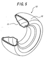
- the reinforcing layer 7 is produced as shown in, for example, FIG. 5 , in which a starting material 12 for the reinforcing layer made of a composite material of fibrous members and rubber is built onto a peripheral face of a hard support 11 having a peripheral shape corresponding to a required outer peripheral face shape of the toric air bag 6 over, for example, its full periphery with no space under the support 11 supporting a large external force, whereby a shaped body 13 for the reinforcing layer as an uncured reinforcing layer can be simply and rapidly formed over a required region of the hard support 11 with higher accuracy as is expected.
- the shaped body 13 for the reinforcing layer is placed in a vulcanization mold together with the support 11 or without the support and then the shaped body 13 is cured through vulcanization, whereby the reinforcing layer 7 can be produced while keeping the high shaping accuracy. This is true in the case of producing the reinforcing layer up to a side face region or an inner peripheral region of the support 11.
- the thus produced reinforcing layer 7 is fitted onto the outer peripheral face of the toric air bag 6 as shown in FIG. 2 , whereby a desired toric reinforced air bag 2 can be formed.
- the reinforcing layer 7 is arranged in the cross section of the toric air bag over a range of not less than 1/3 of a periphery length for expansion-deforming the toric air bag 6 under sufficient equality in the cross section without displacement.
- the reinforcing layer 7 is particularly formed on the shape-stable hard support having a desired shape as previously mentioned, the reinforcing layer 7 can be easily and always formed with higher accuracy without sufficiently preventing the occurrence of wrinkles or the like irrespectively of the width, thickness and the like and even if it is applied over a zone ranging from the crown portion of the support to the side face portion or inner peripheral portion thereof. Therefore, this method can simply and rapidly cope with the change of design or the like of the toric reinforced air bag 2, directly the reinforcing layer 7.
- the uncured toric air bag i.e. ring-shaped body 10 in the figure
- the uncured reinforcing layer i.e. shaped body 13 for the reinforcing layer in the figure
- the uncured constitutional portion is subjected to vulcanization at an integrally united state.
- the uncured constitutional portion can be joined to the cured constitutional portion at a relatively low joining strength.
- the uncured reinforcing layer When the uncured reinforcing layer is built onto the cured toric air bag, the uncured reinforcing layer can be simply and accurately built onto a given position of the toric air bag as is expected. Therefore, when the uncured reinforcing layer is vulcanized while maintaining the built state, a toric reinforced air bag having a high dimensional accuracy can be produced.
- FIG. 6 is a partially cutaway perspective view illustrating another example of a shaped body for the reinforcing layer as an uncured reinforcing layer.
- a narrow-width strip made of a composite material of fibrous members and rubber, preferably strip 14 having a constant width of 10-70 mm is extended onto an outer peripheral face of a hard support 11 having a required cross-sectional outer profile form or substantially an annular form as a whole in substantially a peripheral direction of the support 11 and spirally wound in a widthwise direction with no space between the strips so as to extend over the whole of the widthwise required region of the support 11, whereby a shaped body 13 for the reinforcing layer endlessly extending about the support 11 and having a seamless structure on the periphery is formed.
- the fibrous members in the composite material may be organic fiber cords extending straight in the extending direction of the strip 14, organic or metallic fiber cords extending wavy in the extending direction, or a non-woven fabric, preferably non-woven fabric having no directionality of fibers.
- non-woven fabric can be used the same ones as previously mentioned.
- a shaped body 13 for the reinforcing layer As mentioned above, a shaped body 13 having the required shape and size can be simply and easily formed with higher accuracy.
- an angle ⁇ of the strip 14 with respect to the peripheral direction of the support 11 is within a range of 0-30°.
- the strip 14 can be wound with no space between the strips while overlapping at least widthwise parts of the strips with each other, or while contacting side faces of the strips with each other.
- the overlap amount between the strips 14 can be properly changed in accordance with the widthwise position of the support 11.
- a toric reinforced air bag 2 having a high dimensional accuracy can be constructed by vulcanizing the thus formed shaped body 13 for the reinforcing layer in any one of the aforementioned methods.
- FIG. 7a is a view illustrating a modification example of the cross-sectional outer profile form in the hard support, in which the ring-shaped hard support 11 is provided on its radially inner end portion with a protruding portion 11a flangedly protruding in the widthwise direction for the purpose of forming a winding margin of the uncured reinforcing layer to be formed toward an inner peripheral side of the toric air bag.
- the formation of the shaped body 13 for the reinforcing layer on such a support 11 can be carried out by extending the strip 14 substantially in the peripheral direction and spirally winding it likewise the aforementioned case.
- the shaped body 13 for the reinforcing layer can be formed only by building the strips 14 onto a radially outer face of the support 11, so that the forming operation itself can be facilitated as compared with the case that the strip 14 is built up to a radially inner face side of the support 11 as shown in FIG. 6 .
- the shaped body 13 for the reinforcing layer formed on such a support is taken out from the support 11 before vulcanization, and then built onto a given region of a crown portion of the cured toric air bag 6 and both flangedly protruding side portions 13a of the shaped body 13 for the reinforcing layer are built up to the inner peripheral portions of the toric air bag 6 as shown in FIG. 7b , and thereafter the shaped body 13 for the reinforcing layer is subjected to vulcanization, whereby a product, i.e. a toric reinforced air bag 2 can be formed.
- a partial reinforcement is further required in the thus formed and cured reinforcing layer 7, it is possible to arrange an additional reinforcing layer made of the same composite material or a composite material having different fibrous members in the formation of, for example, the shaped body 13 for the reinforcing layer.
- the additional reinforcing layer is sufficiently and properly arranged on the required region, the winding of the relatively narrow-width strip is not essential, and it is possible to use a wide-width band of the composite material capable of covering the required region by winding.
- the required shaped body 13 for the reinforcing layer can be formed by building the narrow-width strip 14 onto the shape-stable hard support having the required cross-sectional outer profile form. That is, a shaped body 13 having the desired shape and size and capable of surely and adequately arranged on the given position of the toric air bag before or after the vulcanization can be simply and easily produced.
- invention safety tires having a structure shown in FIG. 2 and a tire size of 315/60R22.5 (defined in ETRTO 2000), in which a carcass is comprised of one carcass ply having a radial structure of steel cords, and a reinforcing layer is made of a composite material of a non-woven fabric and a rubber composition, and a toric air bag is made of a soft rubber for a tire tube, and a ratio of the reinforcing layer to a peripheral length of the toric air bag and an adhesion strength therebetween are changed, respectively.
- the running endurance test is conducted on a drum at a speed of 60 km/h under a load of 34.8 kN to evaluate whether or not the tire can be run over 150,000 km as an indication for commercial endurance, while the running endurance test under low pressure is conducted under the same load and speed conditions as mentioned above to measure a running distance until the occurrence of tire trouble as an evaluation by index.
- Table 1-2 Comparative Tires 1 2 3 Construction of reinforcing layer no reinforcing layer joining of reinforcing layer through vulcanization joining of reinforcing layer through vulcanization Ratio of reinforcing layer to periphery length of toric air bag 0 30% 50% Adhesive strength (kN/m) - 6 6 6 Running endurance test (km) trouble (70,000) complete run complete run Running endurance test under low pressure (index) 100 115 120 Insertion of small stone endurance of toric reinforced air bag (index) 100 350 400 trouble form formation of hole formation of hole formation of hole
- a comparative tire 1 has a structure shown in FIG. 1 except the removal of the reinforcing layer, while the reinforcing layer is joined to the toric air bag through vulcanization in comparative tires 2 and 3, respectively.
- Table 1 are also shown evaluation results on endurances of the tire and toric reinforced air bag when the same running endurance test under low pressure as mentioned above is conducted at a state of inserting five broken stone pieces into an interior of the tire.
- the running endurance and the running endurance under low pressure are improved in the invention tires as the width of the reinforcing layer becomes wider with respect to the toric air bag.
- the invention tires are excellent in respect of the endurance of the toric reinforced air bag in the insertion of small stones as compared with the comparative tires 2 and 3 in which the reinforcing layer is joined to the toric air bag through vulcanization and can effectively prevent the breakage of the toric air bag.
- a comparative tire 4 in the above table is constructed by winding one composite material using a non-woven fabric as a fibrous member on a hard support in its peripheral direction one time to form a shaped body for the reinforcing layer. Therefore, the shaped body and hence the reinforcing layer has one joint line on its periphery.
- the invention tires 15-25 each formed by building strips in the peripheral direction can develop excellent running endurance and running endurance under low pressure irrespectively of the strip width or irrespective of the presence or absence of the overlapped portion. Also, since the fibrous member is a non-woven fabric, the endurance of the toric reinforced air bag upon the insertion of the small stones can be improved as compared with the case of using the organic fiber cords as the fibrous member.
- the endurance of the toric air bag upon the insertion of small stones is tendentiously improved even in the invention tires 26-33, in which the strips using the non-woven fabric as the fibrous member are built in the widthwise direction and particularly the width of the strip is 30-80 mm as compared with the case of using the organic fiber cord as the fibrous member.
- the propagation to the toric air bag can be effectively prevented to largely improve the running endurance when the load support is subrogated by the toric reinforced air bag.
- the desired reinforcing layer is produced simply and rapidly and can be accurately fitted onto the required position of the toric air bag, whereby the function of controlling the size growth and the function of stretching in the peripheral direction inherent to the reinforcing layer itself can be sufficiently properly developed, respectively.
- the shaped body for the reinforcing layer is formed by building the strips onto the hard support having the required constant cross-sectional outer profile form, whereby the shaped body for the reinforcing layer having the desired shape and size and capable of always and properly fitting onto the given position of the toric air bag can be produced simply, easily and efficiently.
Description
- This invention relates to a toric reinforced air bag for a safety tire which is used in a safety tire, particularly a safety tire for heavy duty vehicles capable of continuing safe running over a given distance even if an internal tire pressure drops or disappears due to puncture of the tire or the like and which is expansion-deformed based on the drop of the internal tire pressure to subrogate a load support from the tire, and a method of producing the same.
- Heretofore, there have been proposed various tires as a safety tire capable of continuously and safely running to a place provided with an equipment for exchanging or repairing the tire even if the internal tire pressure drops or disappears due to the puncture of the tire, damage of an air valve and the like.
- As an example, there is a tubeless pneumatic tire as shown at a cross section in
FIG. 1 , in which a hollow,toric air bag 102 made of a soft rubber likewise a tire tube is put in an interior of atire 101 and a reinforcinglayer 103 is arranged on an outer peripheral side of a crown portion of theair bag 102 over the full periphery thereof. Such a safety tire is used by assembling thepneumatic tire 101 onto astandard rim 104 and filling a given air pressure into an interior of the tire through avalve 105 and further filling an air pressure higher than the internal tire pressure into an interior of theair bag 102 through anothervalve 106. - The term "standard rim" used herein means a rim specified according to a standard of JATMA YEAR BOOK 2000, ETRTO STANDARD MANUAL 2000, TRA (THE TIRE and RIM ASSOCIATION INC.) YEAR BOOK 2000 or the like. As represented by JATMA YEAR BOOK, the standard rim is an approved rim described in its General Information.
- In the case of running the safety tire under loading in the presence of the given air pressure inside the
tire 101, the rubbing of theair bag 102 with an inner peripheral face of a tread portion in a ground contact region of a tread can be effectively prevented by the action of the reinforcinglayer 103 acting as a member for suppressing size growth of theair bag 102. - On the other hand, if a pressure difference between an inside and an outside of the
air bag 102 exceeds a given value due to the drop or disappearance of the internal tire pressure, theair bag 102 is expansion-deformed under an extension deformation of the reinforcinglayer 103 to approximately uniformly adhere to the inner face of thetire 101 over its full periphery and hence theair bag 102 acts as in the conventional tire tube to subrogate a load support from thetire 101 while controlling deflection deformation of the tire to a small extent, whereby a continuous and safe running can be realized upon puncture of the tire or the like. - In the above proposed technique, when the toric reinforced air bag is constructed by integrally vulcanization-joining the reinforcing
layer 103 on the outer peripheral side of theair bag 102, if a stone or other foreign matter enters, from a punctured hole of the tire into the interior of the tire and sticks into, butts onto or rubs against the reinforcinglayer 103 to create cracks in the reinforcinglayer 103, there is a problem that a danger of prematurely propagating such cracks to theair bag 102 integrally united with the reinforcinglayer 103. - Also, in order to produce the toric reinforced air bag by integrally uniting the reinforcing
layer 103 with theair bag 102 through vulcanization, it is necessary that a starting material for the reinforcing layer is applied onto an outer peripheral face of an uncured air bag having an unstable shape over a given region while suppressing an expansion shape of the uncured air bag as is expected, if necessary, and both the materials are joined through vulcanization, so that there is finally caused a problem that it is difficult to accurately arrange the reinforcinglayer 103 on a given position of theair bag 102. - The invention is made for solving the above problems of the conventional techniques and the object of the invention is to provide a toric reinforced air bag for a safety tire capable of effectively preventing the propagation of cracks to the air bag even if the cracks or the like are created in the reinforcing layer and a method of producing a toric reinforced air bag for a safety tire in which a reinforcing layer can be accurately produced in a desired shape and size and also such a reinforcing layer can be simply and easily fitted onto a desired position of a toric air bag.
- Attention is also drawn to the disclosures of
US-A-2987093 ,US-A-3885614 ,US-A-4963207 , andEP-A-0928702 . - The present invention in one aspect provides a toric reinforced air bag for a safety tire placed inside a tire and inflated under a certain internal pressure, and expansion-deformed accompanied with the drop of the internal tire pressure to subrogate a load support from the tire, in which a crown portion of a toric air bag having a hollow torus shape as a whole is fitted on its outer peripheral side over a full periphery thereof with a reinforcing layer distinct from the air bag, and said reinforcing layer comprises a narrow-width strip of a composite material of rubber and fibrous members spirally wound in a widthwise direction and has a seamless structure on its periphery.
- The invention in another aspect provides a method of producing a toric reinforced air bag for a safety tire placed inside a tire and inflated under a certain internal pressure, and expansion-deformed accompanied with the drop of the internal tire pressure to subrogate a load support from the tire, which comprises spirally winding a narrow-width strip of a composite material of rubber and fibrous members on a hard support having a cross-sectional outer profile form corresponding to a crown portion of a toric air bag having a hollow torus shape as a whole at a cured state in a widthwise direction to form an uncured reinforcing layer, taking out the reinforcing layer from the hard support, and fitting the toric air bag into an inside of the reinforcing layer over a full periphery thereof, and then subjecting to vulcanization.
- Particular embodiments of the invention are the subject of the respective dependent claims.
- The reinforcing layer is made of a composite material of rubber and fibrous members such as wavy cords, organic fiber cords, non-woven fabric or the like.
- When such a toric reinforced air bag is used in a safety tire likewise the above-mentioned case, the rubbing of the toric air bag with an inner peripheral face of a tread portion at a normal state of the tire can be effectively suppressed by the function of the reinforcing layer controlling the size growth, while if the internal tire pressure is lost by puncture of the tire or other damage, the toric air bag can subrogate a load support from the tire under an expansion deformation of the toric air bag based on the extension deformation of the reinforcing layer. Moreover, nitrogen gas or other inert gas may be filled in each of the tire and the toric air bag instead of air.
- Even if cracks are created in the reinforcing layer by foreign matter entered from a punctured hole into the interior of the tire, since the reinforcing layer and the toric air bag are separated from each other at a time of creating the crack in the reinforcing layer, the propagation of the crack from the reinforcing layer to the toric air bag can be effectively suppressed.
- However, when the tire is assembled onto a rim at a state of separating the toric air bag and the reinforcing layer from each other, displacement between the toric air bag and the reinforcing layer is caused and the reinforcing layer can not protect the toric air bag from the foreign matter and also there is a fear that the operability in the assembling onto the rim is deteriorated. It is at least required that the toric air bag and the reinforcing layer are closed to each other in the assembling, while the toric air bag and the reinforcing layer are separated from each other at the time of creating the crack in the reinforcing layer. For this end, it is preferable that the toric air bag and the reinforcing layer are joined at a weak adhesion strength in the assembling thereof.
- If the toric air bag and the reinforcing layer are joined at a strong adhesion strength in the assembling thereof, the displacement therebetween can be prevented, but when a crack is created in the reinforcing layer, they can not be separated from each other and are at an integrally united state and hence the crack is propagated to the toric air bag.
- On the other hand, when the toric air bag and the reinforcing layer are joined with weak adhesion strength in the assembling onto the rim, they are at a state of easily separating from each other after the assembling onto the rim and hence the propagation of the crack to the toric air bag can be prevented even if the crack is created in the reinforcing layer. That is, even if the toric air bag and the reinforcing layer are at a joined state after the assembling onto the rim, since the adhesion strength is weak, the propagation of the crack from the reinforcing layer to the toric air bag can be prevented.
- The term "adhesion strength" used herein means a result obtained according to a peeling test defined in JIS K6301. In this case, a measuring temperature is 20°C.
- The adhesion strength is preferably not more than 4 kN/m, more preferably 0.5-2.0 kN/m.
- In other words, when the adhesion strength exceeds 4 kN/m, the joined state between the toric air bag and the reinforcing layer is too near to the integrally united state through vulcanization joining, so that it is difficult to surely prevent the propagation of the crack from the reinforcing layer to the toric air bag.
- Moreover, when the adhesion strength is less than 0.5 kN/m, there may occur the displacement between the toric air bag and the reinforcing layer, entrance of the foreign matter therebetween, and also there is a fear of deteriorating the operability in the assembling onto the rim and the dissembling therefrom.
- The reinforcing layer has a seamless structure on its periphery. According to this structure, more uniform extension deformation over the full periphery of the reinforcing layer is ensured as compared with a case that the starting materials for the reinforcing layer are lap-joined at one or more places on the periphery to form a joint portions(s) in the reinforcing layer, whereby the toric air bag can be sufficiently uniformly expanded over the full periphery at a time of puncturing the tire.
- Also, it is preferable that the reinforcing layer is fitted onto the toric air bag over a range of not less than 1/3 of a periphery length at a cross section thereof. That is, if the fitting range of the reinforcing layer is too narrow, there is a fear that the foreign matter entered into the tire directly sticks into the toric air bag or rubs therewith. When the fitting range of the reinforcing layer is less than 1/3 of the periphery length, the toric air bag is likely to partially expand toward one side at its cross section in the expansion deformation of the toric air bag and hence deterioration of the durability can not be avoided due to the fact that the toric air bag is not uniformly expansion-deformed at its cross section.
- In the production method of the toric reinforced air bag according to the invention, the reinforcing layer is particularly post-built on the outer peripheral side of the crown portion of the toric air bag having a hollow torus shape as a whole over a full periphery thereof at a cured state of at least one of the toric air bag and the reinforcing layer.
- According to this method, the strong vulcanization joining between the toric air bag and the reinforcing layer can be advantageously prevented irrespective of the necessity of vulcanization after the building of the reinforcing layer, so that the propagation of a crack to the toric air bag in the toric reinforced air bag can be sufficiently prevented.
- Moreover, when the uncured toric air bag is subjected to vulcanization prior to the building of the cured or uncured reinforcing layer, the toric reinforced air bag can be produced with higher accuracy because the reinforcing layer can be simply and accurately built onto a given position of the toric air bag as is expected irrespective of the vulcanization of the reinforcing layer itself.
- This is true in the case that the uncured reinforcing layer is built onto the cured toric air bag and then such a reinforcing layer is subjected to vulcanization. In addition, the reinforcing layer can be relatively weakly joined to the cured toric air bag accompanied with the vulcanization of the reinforcing layer, so that the propagation of a crack from the reinforcing layer to the toric air bag can be sufficiently prevented but also the penetration of foreign matter entered into the tire between the toric air bag and the reinforcing layer can be effectively blocked.
- Preferably, an uncured reinforcing layer having flange-shaped flared portions in its both sides is applied onto the outer peripheral side of the cured toric air bag and then the reinforcing layer is subjected to vulcanization at a state of applying the flared portions of the reinforcing layer onto inner peripheral portions of the toric air bag. According to this method, in addition to the above advantages based on the vulcanization of the reinforcing layer after the building onto the cured toric air bag, a chance of contacting foreign matter entered into the tire with the toric air bag can more advantageously reduced because the inner peripheral side portions of the toric air bag are covered with the flange-shaped flared portions of the uncured reinforcing layer.
- The uncured reinforcing layer can be formed by building a composite material of fibrous member and rubber onto a peripheral face of a hard support having a required outer profile form.
- According to this method, the reinforcing layer having a high dimension accuracy can be simply and rapidly produced by forming the uncured reinforcing layer on the shape-stable hard support without being affected by the toric air bag. Therefore, this reinforcing layer can be always properly fitted onto the required position of the toric air bag irrespective of the vulcanization of the reinforcing layer and hence the toric reinforced air bag can be realized with a high accuracy.
- Also, the reinforcing layer is constructed with the composite material of fibrous member and rubber, so that the required elongation ratio-tensile strength characteristic and other properties can easily be given to the cured reinforcing layer under proper selection of form, density and material of the fibrous member, winding number thereof, rubber properties and so on.
- In this case, a narrow-width strip of the composite material is extended substantially in a peripheral direction of the hard support and spirally wound in a widthwise direction of the hard support to form an uncured reinforcing layer, whereby the reinforcing layer can be made sufficiently uniform over its full periphery as a seamless structure having no joint portion on the periphery but also the reinforcing layer having a required dimension accuracy can be simply and easily formed while preventing the occurrence of wrinkles or the like on the reinforcing layer based on the winding of the narrow-width strip.
- The fibrous member in the composite material may be cords extending straight or wavy in an extending direction of the narrow-width strip or a non-woven fabric. In this case, the function of suppressing the size growth of the toric air bag can be sufficiently developed while ensuring a high rigidity of the reinforcing layer, and also the toric air bag can be equally closed to the inner face of the tire by making the expansion deformation of the toric air bag uniform in the case of causing a given pressure difference. In addition, the formation of the narrow-width strip is easy, and also the desired rigidity distribution can be easily given to the reinforcing layer.
- Also, when a narrow-width strip having a width of 10-70 mm is built onto the hard support to form the uncured reinforcing layer, a high forming operation efficiency can be realized while sufficiently ensuring the building accuracy and operability of the strip.
- It is preferable that the narrow-width strip is built onto the hard support at an angle of 0-30° with respect to a peripheral direction thereof from viewpoints that the strip is properly applied onto the hard support without causing wrinkles and that the rigidity distribution of the reinforcing layer in the peripheral direction thereof is uniformly ensured.
- That is, when the angle exceeds 30°, wrinkles are created in the strip and also it is feared that non-uniform rigidity distribution of the reinforcing layer, bending of the reinforcing layer itself and the like are caused.
- In the winding of the narrow-width strip, at least widthwise parts of the wound strips may be overlapped with each other. In this case, relative rigidity of the reinforcing layer in the widthwise direction and the like can be easily adjusted, if necessary, by changing an overlap amount of the narrow-width strip in the widthwise direction of the hard support.
- On the other hand, it is possible to wind the narrow-width strip while contacting side faces of the strips with each other.
- The uncured reinforcing layer can be formed by building the narrow-width strips onto the hard support so as to extend the strip substantially in the widthwise direction thereof with no space. In this case, the occurrence of wrinkles can be more advantageously suppressed to realize an effective reduction of inferior quality while keeping advantages based on the formation of the reinforcing layer on the hard support.
- In the formation of the reinforcing layer as mentioned above, it is possible to form plural constructional parts for the reinforcing layer on one or more arc-shaped segment supports. In this case, it is possible to miniaturize the shaping equipment. On the other hand, when the shaping is carried out by annually and endlessly building the narrow-width strips on a ring-shaped hard support over its full periphery in a given order, there are some merits in view of the operating number and quality because it is useless to post-join the plural constructional parts for the reinforcing layer shaped on the segment supports to each other.
- Such a formation of the reinforcing layer can be carried out by returning a continuous narrow-width strip at each side end of a hard support to build zigzag thereonto, or by building many short-length narrow-width strips on a hard support so as to straightforward extend the strip from one side edge of the support to the other side edge thereof.
- The invention will be further described with reference to the accompanying drawings, in which
-
FIG. 1 is a widthwise section view of a conventional safety tire. -
FIG. 2 is a widthwise section view of an embodiment of the safety tire according to the invention. -
FIG. 3 is a diagrammatic view of a hollow shaped body for producing an uncured toric air bag. -
FIG. 4 is a perspective view of a ring-shaped body as an uncured toric air bag. -
FIG. 5 is a sectionally perspective view illustrating a forming example of a shaped body for a reinforcing layer. -
FIG. 6 is a sectionally perspective view illustrating another forming example of a shaped body for a reinforcing layer. -
FIG. 7 is a diagrammatic view illustrating the other forming example and an application example of a shaped body for a reinforcing layer. -
FIG. 2 is a cross section view of a safety tire incorporated with a toric reinforced air bag according to the invention, which shows a state that the toric reinforced air bag is placed in a tire assembled onto a standard rim and a given air pressure P1 (gauge pressure), for example a maximum air pressure described in the aforementioned JATMA YEAR BOOK is filled in the interior of the tire and an air pressure P2 higher by 20 kPa or more than the air pressure P1 is filled in the interior of the toric reinforced air bag. - In this figure, numeral 1 is a tubeless pneumatic tire, numeral 2 a toric reinforced air bag placed in the tire, numeral 3 a standard rim assembled with the tire 1, and
numerals toric air bag 2, respectively. - The illustrated toric reinforced
air bag 2 is constructed by fitting a reinforcinglayer 7 separated from a toric air bag and having preferably a seamless structure in a peripheral direction onto an outer peripheral side of a crown portion of atoric air bag 6 having a hollow torus shape as a whole over the full periphery thereof. In this case, both the air bag and the reinforcing layer may be at a completely non-joint state or may be joined at a low strength with or without an adhesive. - When the reinforcing
layer 7 is joined to thetoric air bag 6, it is preferable that the adhesion strength therebetween, i.e. adhesion strength according to a peeling test defined in JIS K6301,is not more than 4 kN/m, more preferably 0.5-2 kN/m. - In this case, the position displacement between the toric air bag and the reinforcing layer is prevented on and after the production of the toric reinforced air bag but also the propagation of a crack in the reinforcing layer to the toric air bag is prevented as previously mentioned, while the invasion of foreign matter between the
toric air bag 6 and the reinforcinglayer 7 can be more advantageously prevented. - The reinforcing
layer 7 in the toric reinforcedair bag 2 preferably has an elongation amount in a peripheral direction of not less than 15% in the subrogation of load support by, for example, the toric reinforcedair bag 2 for suppressing a crushed deformation amount of the tire 1. In this case, the elongation deformation may be a range of elastic region of the reinforcinglayer 7 or a range from elastic region to plastic region thereof. - For instance, when the reinforcing
layer 7 is made of a composite material formed by covering straight extending organic fiber cords with a rubber composition, the elongation deformation is frequently done in an elastic region of the organic fiber cord. Also, when the reinforcing layer is made of a composite material formed by covering wavy cords with a rubber composition, the elongation deformation is done in an elastic region causing disappearance of wave form of the cord. On the other hand, when the reinforcinglayer 7 is made of a composite material of non-woven fabric and rubber composition, the elongation deformation is usually done in a plastic region disengaging the intertwisting of fibers in the non-woven fabric. - As the fiber of the non-woven fabric used in the reinforcing
layer 7, use may be made of natural polymer fibers such as cotton, cellulose and the like; synthetic polymer fibers such as aromatic polyamide fiber, aliphatic polyamide fiber, polyester fiber, polyvinyl alcohol fiber, rayon fiber, polyolefin ketone fiber, polybenzoxazole fiber and the like; and inorganic fibers such as glass fiber, carbon fiber, steel filament and the like. As the aromatic polyamide fiber, mention may be made of polyparaphenylene terephthalamide, polymethaphenylene terephthalamide, polyparaphenylene isophthalamide, polymethaphenylene isophthalamide and the like. These fibers may be used alone or in a combination of two or more. - These fibers may have any cross sectional shapes such as circle, ellipse, polygon and so on, and fibers having a hollow portion therein may be used. Further, there may be used composite fibers of a core-sheath structure, - type shape, petal type shape, lamellar shape or the like in which different materials are applied to inner and outer layers, respectively. If these fibers are sufficiently adhered to a matrix rubber in the composite after the vulcanization, it is not required that such a fiber is previously subjected to an adhesion treatment. However, if the adhesion is not sufficient, the fiber is subjected to the adhesion treatment.
- As a method of producing the non-woven fabric, a needle punching method, a carding method, a melt blowing method, and a spun bonding method are all suitable. Among these methods, the carding method of entangling fibers through a water stream or needles and the spun bonding method of joining fibers to each other are more suitable for the non-woven fabric to be produced.
- In the rubber composition applied to the non-woven fabric, rubber component is not particularly limited, but diene rubbers such as natural rubber, butadiene rubber, styrene-butadiene rubber, isoprene rubber and the like are preferable. Also, the rubber composition preferably has a tensile stress at 50% elongation M50 of 2.0-9.0 MPa and a tensile stress at 100% elongation M100 of 4.0-15.0 MPa.
- Moreover, it is preferable that a weight of the non-woven fabric in the rubber composition is within a range of 10-300 g/m2. When the weight of the non-woven fabric is less than 10 g/m2, it is difficult to maintain the uniformity of the non-woven fabric and the unevenness of fiber distribution becomes large and hence scattering in the strength, rigidity and elongation at break of the reinforcing
layer 7 made of the composite body of cured rubber composition and non-woven fabric becomes large, while when the weight exceeds 300 g/m2, it is difficult to penetrate the rubber composition into spaces inside the non-woven fabric dependent upon the fluidity of the rubber composition, and hence the uniformity of the reinforcinglayer 7 is easily damaged. In any case, a weight outside the above range is unfavourable. - The toric
rubbery air bag 6 in the toric reinforcedair bag 2 can be produced, for example, as follows. - As shown in
FIG. 3 , a flat and hollow rubber shaped body 9 having ahollow portion 8 formed by spraying or applying a lubricant or releasing agent such as stearic acid in a central part in its thickness direction is extruded in the form of a band and cut into a given length, and avalve 5 capable of supplying or releasing pressure in thehollow portion 8 is attached to the cut shaped body 9. Then, both ends of the cut shaped body 9 are butt-joined in an endless form at a state of locating thevalve 5 at an inner peripheral side as shown inFIG. 4 to form a ring-shapedbody 10 having a continuoushollow portion 8 therein as an uncured toric air bag. - Thereafter, the ring-shaped
body 10 is expanded by supplying an internal pressure such as pressurized air or the like through thevalve 5 into thehollow portion 8 and placed in an interior of a vulcanization mold and further expanded in the vulcanization mold so as to close the whole of the ring-shapedbody 10 to an inner face of the mold and cured through vulcanization to obtain a toric air bag product. - On the other hand, the reinforcing
layer 7 is produced as shown in, for example,FIG. 5 , in which a startingmaterial 12 for the reinforcing layer made of a composite material of fibrous members and rubber is built onto a peripheral face of ahard support 11 having a peripheral shape corresponding to a required outer peripheral face shape of thetoric air bag 6 over, for example, its full periphery with no space under thesupport 11 supporting a large external force, whereby a shapedbody 13 for the reinforcing layer as an uncured reinforcing layer can be simply and rapidly formed over a required region of thehard support 11 with higher accuracy as is expected. - Thereafter, the shaped
body 13 for the reinforcing layer is placed in a vulcanization mold together with thesupport 11 or without the support and then the shapedbody 13 is cured through vulcanization, whereby the reinforcinglayer 7 can be produced while keeping the high shaping accuracy. This is true in the case of producing the reinforcing layer up to a side face region or an inner peripheral region of thesupport 11. - The thus produced reinforcing
layer 7 is fitted onto the outer peripheral face of thetoric air bag 6 as shown inFIG. 2 , whereby a desired toric reinforcedair bag 2 can be formed. - In this case, it is preferable that the reinforcing
layer 7 is arranged in the cross section of the toric air bag over a range of not less than 1/3 of a periphery length for expansion-deforming thetoric air bag 6 under sufficient equality in the cross section without displacement. - When the
toric air bag 6 and the reinforcinglayer 7 are separately and independently produced according to the method of the invention, if the reinforcinglayer 7 is particularly formed on the shape-stable hard support having a desired shape as previously mentioned, the reinforcinglayer 7 can be easily and always formed with higher accuracy without sufficiently preventing the occurrence of wrinkles or the like irrespectively of the width, thickness and the like and even if it is applied over a zone ranging from the crown portion of the support to the side face portion or inner peripheral portion thereof. Therefore, this method can simply and rapidly cope with the change of design or the like of the toric reinforcedair bag 2, directly the reinforcinglayer 7. - Although the above is described with respect to the case that the reinforcing
layer 7 as a cure product is built onto thetoric air bag 6 as a cured product, it is possible that the uncured toric air bag, i.e. ring-shapedbody 10 in the figure, or the uncured reinforcing layer, i.e. shapedbody 13 for the reinforcing layer in the figure are built onto the cured reinforcinglayer 7 ortoric air bag 6 and then the uncured constitutional portion is subjected to vulcanization at an integrally united state. In the latter case, the uncured constitutional portion can be joined to the cured constitutional portion at a relatively low joining strength. - When the uncured reinforcing layer is built onto the cured toric air bag, the uncured reinforcing layer can be simply and accurately built onto a given position of the toric air bag as is expected. Therefore, when the uncured reinforcing layer is vulcanized while maintaining the built state, a toric reinforced air bag having a high dimensional accuracy can be produced.
-
FIG. 6 is a partially cutaway perspective view illustrating another example of a shaped body for the reinforcing layer as an uncured reinforcing layer. - A narrow-width strip made of a composite material of fibrous members and rubber, preferably strip 14 having a constant width of 10-70 mm is extended onto an outer peripheral face of a
hard support 11 having a required cross-sectional outer profile form or substantially an annular form as a whole in substantially a peripheral direction of thesupport 11 and spirally wound in a widthwise direction with no space between the strips so as to extend over the whole of the widthwise required region of thesupport 11, whereby a shapedbody 13 for the reinforcing layer endlessly extending about thesupport 11 and having a seamless structure on the periphery is formed. - In this case, the fibrous members in the composite material may be organic fiber cords extending straight in the extending direction of the
strip 14, organic or metallic fiber cords extending wavy in the extending direction, or a non-woven fabric, preferably non-woven fabric having no directionality of fibers. - As the non-woven fabric can be used the same ones as previously mentioned.
- When the constant-
width strip 14 made of the composite material of such fibrous members and a rubber composition impregnating, penetrating, coating or the like thereto is extended substantially in the peripheral direction of the ring-shapedhard support 11 and built thereonto to form a shapedbody 13 for the reinforcing layer as mentioned above, a shapedbody 13 having the required shape and size can be simply and easily formed with higher accuracy. - In the formation of the shaped
body 13 for the reinforcing layer, it is preferable that an angle θ of thestrip 14 with respect to the peripheral direction of thesupport 11 is within a range of 0-30°. Also, thestrip 14 can be wound with no space between the strips while overlapping at least widthwise parts of the strips with each other, or while contacting side faces of the strips with each other. - In the former case, the overlap amount between the
strips 14 can be properly changed in accordance with the widthwise position of thesupport 11. - A toric reinforced
air bag 2 having a high dimensional accuracy can be constructed by vulcanizing the thus formed shapedbody 13 for the reinforcing layer in any one of the aforementioned methods. -
FIG. 7a is a view illustrating a modification example of the cross-sectional outer profile form in the hard support, in which the ring-shapedhard support 11 is provided on its radially inner end portion with a protrudingportion 11a flangedly protruding in the widthwise direction for the purpose of forming a winding margin of the uncured reinforcing layer to be formed toward an inner peripheral side of the toric air bag. - The formation of the shaped
body 13 for the reinforcing layer on such asupport 11 can be carried out by extending thestrip 14 substantially in the peripheral direction and spirally winding it likewise the aforementioned case. - In this case, the shaped
body 13 for the reinforcing layer can be formed only by building thestrips 14 onto a radially outer face of thesupport 11, so that the forming operation itself can be facilitated as compared with the case that thestrip 14 is built up to a radially inner face side of thesupport 11 as shown inFIG. 6 . - Although the outer profile form of the
support 11 shown inFIG. 7a largely differs from that of the toric air bag inflated under an internal pressure, the shapedbody 13 for the reinforcing layer formed on such a support is taken out from thesupport 11 before vulcanization, and then built onto a given region of a crown portion of the curedtoric air bag 6 and both flangedly protrudingside portions 13a of the shapedbody 13 for the reinforcing layer are built up to the inner peripheral portions of thetoric air bag 6 as shown inFIG. 7b , and thereafter the shapedbody 13 for the reinforcing layer is subjected to vulcanization, whereby a product, i.e. a toric reinforcedair bag 2 can be formed. - If a partial reinforcement is further required in the thus formed and cured reinforcing
layer 7, it is possible to arrange an additional reinforcing layer made of the same composite material or a composite material having different fibrous members in the formation of, for example, the shapedbody 13 for the reinforcing layer. In so far as the additional reinforcing layer is sufficiently and properly arranged on the required region, the winding of the relatively narrow-width strip is not essential, and it is possible to use a wide-width band of the composite material capable of covering the required region by winding. - As mentioned above, the required shaped
body 13 for the reinforcing layer can be formed by building the narrow-width strip 14 onto the shape-stable hard support having the required cross-sectional outer profile form. That is, a shapedbody 13 having the desired shape and size and capable of surely and adequately arranged on the given position of the toric air bag before or after the vulcanization can be simply and easily produced. - The invention will be further described with reference to the following Examples.
- There are provided invention safety tires having a structure shown in
FIG. 2 and a tire size of 315/60R22.5 (defined in ETRTO 2000), in which a carcass is comprised of one carcass ply having a radial structure of steel cords, and a reinforcing layer is made of a composite material of a non-woven fabric and a rubber composition, and a toric air bag is made of a soft rubber for a tire tube, and a ratio of the reinforcing layer to a peripheral length of the toric air bag and an adhesion strength therebetween are changed, respectively. After each of these tires is assembled onto a standard rim, a running endurance test under conditions that an air pressure filled in the tire is 900 kPa as a gauge pressure and an air pressure filled in the toric reinforced air bag is 950 kPa as a gauge pressure and a running endurance test under low pressure condition that an internal pressure of the toric reinforced air bag is 450 kPa through its expansion deformation at a puncture state of rendering the internal tire pressure into 0 kPa are carried out to obtain results as shown in Table 1. - The running endurance test is conducted on a drum at a speed of 60 km/h under a load of 34.8 kN to evaluate whether or not the tire can be run over 150,000 km as an indication for commercial endurance, while the running endurance test under low pressure is conducted under the same load and speed conditions as mentioned above to measure a running distance until the occurrence of tire trouble as an evaluation by index. The larger the index value, the better the result.

Table 1-2 Comparative Tires 1 2 3 Construction of reinforcing layer no reinforcing layer joining of reinforcing layer through vulcanization joining of reinforcing layer through vulcanization Ratio of reinforcing layer to periphery length of toric air bag 0 30% 50% Adhesive strength (kN/m) - 6 6 Running endurance test (km) trouble (70,000) complete run complete run Running endurance test under low pressure (index) 100 115 120 Insertion of small stone endurance of toric reinforced air bag (index) 100 350 400 trouble form formation of hole formation of hole formation of hole - In Table 1, a comparative tire 1 has a structure shown in
FIG. 1 except the removal of the reinforcing layer, while the reinforcing layer is joined to the toric air bag through vulcanization incomparative tires 2 and 3, respectively. - In Table 1 are also shown evaluation results on endurances of the tire and toric reinforced air bag when the same running endurance test under low pressure as mentioned above is conducted at a state of inserting five broken stone pieces into an interior of the tire.
- As seen from Table 1, the running endurance and the running endurance under low pressure are improved in the invention tires as the width of the reinforcing layer becomes wider with respect to the toric air bag. Also, the invention tires are excellent in respect of the endurance of the toric reinforced air bag in the insertion of small stones as compared with the
comparative tires 2 and 3 in which the reinforcing layer is joined to the toric air bag through vulcanization and can effectively prevent the breakage of the toric air bag. - With respect to invention tires in which the structure of the reinforcing layer is variously changed and the ratio of the reinforcing layer to the periphery length of the toric air bag is 60% and the adhesion strength therebetween is 1.5 kN/m, the running endurance test and the running endurance test under low pressure are conducted under the same conditions as in Example 1 to obtain results as shown in Table 2.
- Even in this case, the larger the index value, the better the result.

- A
comparative tire 4 in the above table is constructed by winding one composite material using a non-woven fabric as a fibrous member on a hard support in its peripheral direction one time to form a shaped body for the reinforcing layer. Therefore, the shaped body and hence the reinforcing layer has one joint line on its periphery. - As seen from Table 2, the invention tires 15-25 each formed by building strips in the peripheral direction can develop excellent running endurance and running endurance under low pressure irrespectively of the strip width or irrespective of the presence or absence of the overlapped portion. Also, since the fibrous member is a non-woven fabric, the endurance of the toric reinforced air bag upon the insertion of the small stones can be improved as compared with the case of using the organic fiber cords as the fibrous member.
- Moreover, when the angle of the strip is 50° with respect to the peripheral direction, the deterioration of the endurance of the toric reinforced air bag upon the insertion of small stones is not avoided.
- Further, it is understood that the endurance of the toric air bag upon the insertion of small stones is tendentiously improved even in the invention tires 26-33, in which the strips using the non-woven fabric as the fibrous member are built in the widthwise direction and particularly the width of the strip is 30-80 mm as compared with the case of using the organic fiber cord as the fibrous member.
- In the toric reinforced air bag according to the invention, even if cracks or other damage are caused in the reinforcing layer, the propagation to the toric air bag can be effectively prevented to largely improve the running endurance when the load support is subrogated by the toric reinforced air bag. According to the method of producing the toric reinforced air bag according to the invention, the desired reinforcing layer is produced simply and rapidly and can be accurately fitted onto the required position of the toric air bag, whereby the function of controlling the size growth and the function of stretching in the peripheral direction inherent to the reinforcing layer itself can be sufficiently properly developed, respectively.
- Further, according to the method of producing the shaped body for the reinforcing layer according to the invention, the shaped body for the reinforcing layer is formed by building the strips onto the hard support having the required constant cross-sectional outer profile form, whereby the shaped body for the reinforcing layer having the desired shape and size and capable of always and properly fitting onto the given position of the toric air bag can be produced simply, easily and efficiently.
Claims (13)
- A toric reinforced air bag (2) for a safety tire placed inside a tire (1) and inflated under a certain internal pressure, and expansion-deformed accompanied with the drop of the internal tire pressure to subrogate a load support from the tire, in which a crown portion of a toric air bag (6) having a hollow torus shape as a whole is fitted on its outer peripheral side over a full periphery thereof with a reinforcing layer (7) distinct from the air bag, and said reinforcing layer comprises a narrow-width strip (14) of a composite material of rubber and fibrous members spirally wound in a widthwise direction and has a seamless structure on its periphery.
- A toric reinforced air bag as claimed in claim 1, wherein the reinforcing layer (7) is joined to the toric air bag (6) at an adhesion strength of not more than 4 kN/m.
- A toric reinforced air bag as claimed in claim 1 or 2, wherein the reinforcing layer (7) is fitted onto the toric air bag (6) over a range of not less than 1/3 of a periphery length at a cross section thereof.
- A method of producing a toric reinforced air bag (2) for a safety tire placed inside a tire (1) and inflated under a certain internal pressure, and expansion-deformed accompanied with the drop of the internal tire pressure to subrogate a load support from the tire, which comprises spirally winding a narrow-width strip (14) of a composite material of rubber and fibrous members on a hard support (11) having a cross-sectional outer profile form corresponding to a crown portion of a toric air bag (6) having a hollow torus shape as a whole at a cured state in a widthwise direction to form an uncured reinforcing layer (7), taking out the reinforcing layer (7) from the hard support (11), and fitting the toric air bag (6) into an inside of the reinforcing layer over a full periphery thereof, and then subjecting to vulcanization.
- A method as claimed in claim 4, wherein an uncured reinforcing layer (7) having flange-shaped flared portions in its both sides is applied onto the outer peripheral side of the cured toric air bag (6) and then the reinforcing layer is subjected to vulcanization at a state of applying the flared portions of the reinforcing layer onto inner peripheral portions of the toric air bag.
- A method as claimed in claim 4 or 5, wherein the fibrous member is cords extending straight or wavy in an extending direction of the narrow-width strip (14) or a non-woven fabric.
- A method as claimed in claim 6, wherein the narrow-width strip (14) has a width of 10-70 mm.
- A method as claimed in claim 6 or 7, wherein the narrow-width strip (14) is built onto a hard support (11) at an angle of 0-30° with respect to a peripheral direction thereof.
- A method as claimed in any of claims 6 to 8, wherein the narrow-width strip (14) is wound so that at least widthwise parts of the wound strips are overlapped with each other.
- A method as claimed in claim 9, wherein an overlap amount of the narrow-width strip (14) is changed in the widthwise direction of a hard support (11).
- A method as, claimed in any of claims 6 to 8, wherein the narrow-width strip (14) is wound while contacting side faces of the strips with each other.
- A method as claimed in claim 6 or 7, wherein the uncured reinforcing layer (7) is formed by building narrow-width strips (14) onto a hard support (11) so as to extend the strip substantially in the widthwise direction thereof with no spacing between the narrow-width strips.
- A method as claimed in claim 6, 7 or 12, wherein the narrow-width strip (14) is built on a ring-shaped hard support (11) over its full periphery.
Applications Claiming Priority (7)
| Application Number | Priority Date | Filing Date | Title |
|---|---|---|---|
| JP2001159814 | 2001-05-29 | ||
| JP2001159814 | 2001-05-29 | ||
| JP2002037190 | 2002-02-14 | ||
| JP2002037191 | 2002-02-14 | ||
| JP2002037191 | 2002-02-14 | ||
| JP2002037190 | 2002-02-14 | ||
| PCT/JP2002/005217 WO2002096678A1 (en) | 2001-05-29 | 2002-05-29 | Reinforced air bladder for safety tire, method of manufacturing the air bladder, and method of manufacturing reinforced layer formed body |
Publications (3)
| Publication Number | Publication Date |
|---|---|
| EP1398183A1 EP1398183A1 (en) | 2004-03-17 |
| EP1398183A4 EP1398183A4 (en) | 2004-12-01 |
| EP1398183B1 true EP1398183B1 (en) | 2008-06-11 |
Family
ID=27346804
Family Applications (1)
| Application Number | Title | Priority Date | Filing Date |
|---|---|---|---|
| EP02728190A Expired - Fee Related EP1398183B1 (en) | 2001-05-29 | 2002-05-29 | Reinforced air bladder for safety tire, method of manufacturing the air bladder and method of manufacturing reinforced layer formed body |
Country Status (6)
| Country | Link |
|---|---|
| US (2) | US7165587B2 (en) |
| EP (1) | EP1398183B1 (en) |
| JP (1) | JP4393070B2 (en) |
| DE (1) | DE60227073D1 (en) |
| ES (1) | ES2307749T3 (en) |
| WO (1) | WO2002096678A1 (en) |
Families Citing this family (23)
| Publication number | Priority date | Publication date | Assignee | Title |
|---|---|---|---|---|
| WO2004108437A1 (en) * | 2003-06-06 | 2004-12-16 | Bridgestone Corporation | Air bladder for safety tire |
| US20050109439A1 (en) * | 2003-11-13 | 2005-05-26 | Droegemueller David S. | Integrated tire rim airbag system |
| CN100473550C (en) * | 2004-06-02 | 2009-04-01 | 株式会社普利司通 | Reinforcing air envelope for safety tire |
| WO2005118316A1 (en) | 2004-06-02 | 2005-12-15 | Bridgestone Corporation | Reinforcing air envelope for safety tire |
| US20090008013A1 (en) * | 2004-07-27 | 2009-01-08 | Bridgestone Corporation | Air Bladder for Safety Tire |
| FR2874616B1 (en) * | 2004-08-31 | 2007-06-01 | Ruiz Maria Amelia Ramon | HOMOGENEOUS CHEMICAL RANGE OF HIGH VISCOSITY ANTI-CUP FLUID AND ITS VARIANTS, FORMING AN ADDITIONAL REINFORCING LAYER ON THE TREAD BAND AND ON THE FLANKS OF TIRES |
| JP4549169B2 (en) * | 2004-11-26 | 2010-09-22 | 株式会社ブリヂストン | Pneumatic bladders and safety tires for safety tires |
| US8615409B1 (en) | 2005-04-15 | 2013-12-24 | Recovery Data-Connect, L.L.C. | System and method for identification, perfection, collection, and valuation of third-party claims including subrogation claims |
| CN101198483B (en) * | 2005-06-15 | 2010-05-19 | 株式会社普利司通 | Air bladder for safety tire and safety tire using the same |
| JP2007118803A (en) * | 2005-10-28 | 2007-05-17 | Bridgestone Corp | Air sack for safety tire and safety tire |
| JP4750544B2 (en) * | 2005-11-30 | 2011-08-17 | 株式会社ブリヂストン | Pneumatic bladders and safety tires for safety tires |
| US8356647B2 (en) * | 2006-06-02 | 2013-01-22 | Bridgestone Corporation | Pneumatic tire |
| EP2058114B1 (en) * | 2006-08-28 | 2012-04-18 | Toyo Tire & Rubber Co. Ltd. | Method for manufacturing tire |
| JP2008074268A (en) * | 2006-09-21 | 2008-04-03 | Bridgestone Corp | Air bladder for safety tire |
| JP2010130899A (en) | 2007-03-14 | 2010-06-17 | Ajinomoto Co Inc | Microorganism producing l-glutamic acid-based amino acid, and method for producing amino acid |
| JP5078435B2 (en) * | 2007-05-21 | 2012-11-21 | 株式会社ブリヂストン | Air sac vulcanizing method and air sac vulcanizing system |
| EP2219887A1 (en) * | 2007-12-14 | 2010-08-25 | Michele De Carlo | Tire with a puncture protection strip |
| WO2015006432A1 (en) | 2013-07-09 | 2015-01-15 | Hybrid Electric Conversion Co., Llc | Pneumatic tire security system employing internal high pressure air bag |
| US10632699B2 (en) | 2015-06-25 | 2020-04-28 | Bridgestone Americas Tire Operations, Llc | Bladder rings for tire vulcanization mold |
| CN113365854B (en) * | 2019-03-19 | 2023-03-28 | 沈宗和 | Tubeless tire assembly with single-section structure |
| CN110385946A (en) * | 2019-07-29 | 2019-10-29 | 江西科技学院 | A kind of tire assembly and automobile |
| CN110978895B (en) * | 2019-12-05 | 2022-04-01 | 怀化沃普环保科技有限公司 | Combined type explosion-proof tire |
| CN112406418A (en) * | 2020-11-13 | 2021-02-26 | 湖南成鑫专用汽车有限公司 | High-safety automobile tire |
Family Cites Families (31)
| Publication number | Priority date | Publication date | Assignee | Title |
|---|---|---|---|---|
| US584289A (en) * | 1897-06-08 | moeg-an | ||
| US1144239A (en) * | 1915-02-23 | 1915-06-22 | Reinforced Inner Tube Company | Inner tube for pneumatic tires. |
| US2244941A (en) * | 1939-04-26 | 1941-06-10 | William H Degnen | Inner tube |
| US2510974A (en) * | 1945-02-14 | 1950-06-13 | Hainlen Anna | Safety inner tube for pneumatic tires |
| NL108868C (en) | 1957-07-22 | |||
| GB987983A (en) * | 1961-03-08 | 1965-03-31 | Dunlop Rubber Co | Improvements in or relating to the manufacture of pneumatic tyres |
| US3802982A (en) * | 1970-01-06 | 1974-04-09 | Steelastic Co | Reinforced tire fabric and method and apparatus for making same |
| US3724521A (en) | 1971-05-06 | 1973-04-03 | Exxon Research Engineering Co | Anti-flat device |
| JPS5249602B2 (en) * | 1972-10-21 | 1977-12-19 | ||
| US3933114A (en) * | 1973-08-06 | 1976-01-20 | Brunswick Corporation | Self-purging tell-tale nozzle |
| JPS5233668B2 (en) * | 1973-08-09 | 1977-08-30 | ||
| US3993114A (en) * | 1974-03-13 | 1976-11-23 | Hinderks M V | Pneumatic tire |
| US4008743A (en) * | 1975-08-27 | 1977-02-22 | The General Tire & Rubber Company | Pneumatic tire with puncture resistance internal safety structure |
| DE2553449A1 (en) * | 1975-11-28 | 1977-06-08 | Continental Gummi Werke Ag | Vehicle wheel tube for emergency running - has reinforcement of woven cord layers contracting laterally as dia. increases |
| US4126720A (en) * | 1976-05-21 | 1978-11-21 | Edwards George R | Radial tire manufacturing method |
| US4164250A (en) * | 1976-11-15 | 1979-08-14 | Uniroyal, Inc. | Nail-deflecting, inner-tube assembly for run-flat tires |
| US4137894A (en) | 1977-06-17 | 1979-02-06 | The Firestone Tire & Rubber Company | Pneumatic tire, rim and run-flat system combination |
| DE3014213A1 (en) * | 1980-04-14 | 1981-10-15 | Uniroyal Englebert Reifen GmbH, 5100 Aachen | EMERGENCY WHEEL |
| FR2603841B1 (en) * | 1986-09-17 | 1989-02-24 | Michelin & Cie | METHOD OF MANUFACTURING A TIRE WITH LAYING RUBBER PRODUCTS AND REINFORCING ELEMENTS ON A SUPPORT, DEVICE FOR LAYING RUBBER PRODUCTS AND MACHINE USING SUCH DEVICE (S) |
| JPH02182507A (en) * | 1989-01-05 | 1990-07-17 | Sumitomo Rubber Ind Ltd | Assembly of radial tire and rim |
| EP0453294B1 (en) * | 1990-04-18 | 1995-07-05 | Sumitomo Rubber Industries Limited | Belted radial tyre for motorcycle and belt making method |
| JPH05104916A (en) * | 1990-12-29 | 1993-04-27 | Yoshiaki Watanabe | Tire with internal partition wall |
| ES2208860T3 (en) | 1997-12-30 | 2004-06-16 | Pirelli Pneumatici Societa' Per Azioni | TIRE FOR VEHICLE WHEELS. |
| JP2002059718A (en) * | 2000-08-23 | 2002-02-26 | Bridgestone Corp | Safety pneumatic tire |
| JP2002059719A (en) * | 2000-08-23 | 2002-02-26 | Bridgestone Corp | Safety pneumatic tire |
| JP2002067632A (en) * | 2000-08-24 | 2002-03-08 | Bridgestone Corp | Safety pneumatic tire |
| JP2002067631A (en) * | 2000-09-01 | 2002-03-08 | Bridgestone Corp | Safety pneumatic tire |
| JP2002120526A (en) * | 2000-10-19 | 2002-04-23 | Bridgestone Corp | Air bag for safety tire, and safety tire using it |
| JP2002144444A (en) * | 2000-11-09 | 2002-05-21 | Bridgestone Corp | Method for producing air bag for safety tire and air bag |
| WO2002043975A1 (en) * | 2000-11-30 | 2002-06-06 | Bridgestone Corporation | Air bladder for safe tire |
| JP4358467B2 (en) * | 2001-05-24 | 2009-11-04 | 株式会社ブリヂストン | Rubber-fiber composite material and rubber article using the same |
-
2002
- 2002-05-29 WO PCT/JP2002/005217 patent/WO2002096678A1/en active IP Right Grant
- 2002-05-29 US US10/478,990 patent/US7165587B2/en not_active Expired - Fee Related
- 2002-05-29 ES ES02728190T patent/ES2307749T3/en not_active Expired - Lifetime
- 2002-05-29 JP JP2002593170A patent/JP4393070B2/en not_active Expired - Fee Related
- 2002-05-29 EP EP02728190A patent/EP1398183B1/en not_active Expired - Fee Related
- 2002-05-29 DE DE60227073T patent/DE60227073D1/en not_active Expired - Lifetime
-
2006
- 2006-11-15 US US11/599,406 patent/US20070056678A1/en not_active Abandoned
Also Published As
| Publication number | Publication date |
|---|---|
| US7165587B2 (en) | 2007-01-23 |
| WO2002096678A1 (en) | 2002-12-05 |
| DE60227073D1 (en) | 2008-07-24 |
| JPWO2002096678A1 (en) | 2004-09-09 |
| EP1398183A4 (en) | 2004-12-01 |
| EP1398183A1 (en) | 2004-03-17 |
| US20040177909A1 (en) | 2004-09-16 |
| US20070056678A1 (en) | 2007-03-15 |
| JP4393070B2 (en) | 2010-01-06 |
| ES2307749T3 (en) | 2008-12-01 |
Similar Documents
| Publication | Publication Date | Title |
|---|---|---|
| EP1398183B1 (en) | Reinforced air bladder for safety tire, method of manufacturing the air bladder and method of manufacturing reinforced layer formed body | |
| KR100850694B1 (en) | Method of manufacturing pneumatic tire | |
| EP1752315B1 (en) | Reinforcing air envelope for safety tire | |
| US6415840B1 (en) | Pneumatic safety tire with rubber-organic filament fiber layer | |
| US6814118B2 (en) | Pneumatic tire with specified airtight layer on inner surface | |
| CZ444099A3 (en) | Radial pneumatic tyre | |
| CN103889740A (en) | Pneumatic tire | |
| EP2676788A1 (en) | Rubber patch for repairing radial tires, method for repairing radial tires using same, and repaired radial tire | |
| US10099517B2 (en) | Side-reinforced run-flat tire | |
| US4569381A (en) | Pneumatic tires having a high resistance to cut growth | |
| JP4257723B2 (en) | Tire and rim assembly | |
| JPH05310013A (en) | Runflat pneumatic radial tire | |
| JP2004009666A (en) | Pneumatic radial tire for aircraft and its manufacturing method | |
| JPH0645192B2 (en) | Radial tire manufacturing method | |
| EP2067635B1 (en) | Radial tire for aircraft and its production method | |
| US20170174010A1 (en) | Pneumatic tire with a sealant component | |
| JP3982901B2 (en) | Pneumatic tire | |
| JP4259732B2 (en) | Pneumatic tire and manufacturing method thereof | |
| EP1637361B1 (en) | Air bladder for safety tire | |
| JP3686197B2 (en) | Pneumatic tire | |
| PL179190B1 (en) | Pneumatic tyre and non-vulcanised pneumatic carcass | |
| GB1598298A (en) | Radial pneumatic tyres | |
| JPH11151906A (en) | Pneumatic radial tire and manufacture thereof | |
| JPH1199808A (en) | Pneumatic radial tyre |
Legal Events
| Date | Code | Title | Description |
|---|---|---|---|
| PUAI | Public reference made under article 153(3) epc to a published international application that has entered the european phase |
Free format text: ORIGINAL CODE: 0009012 |
|
| 17P | Request for examination filed |
Effective date: 20031201 |
|
| AK | Designated contracting states |
Kind code of ref document: A1 Designated state(s): AT BE CH CY DE DK ES FI FR GB GR IE IT LI LU MC NL PT SE TR |
|
| A4 | Supplementary search report drawn up and despatched |
Effective date: 20041015 |
|
| 17Q | First examination report despatched |
Effective date: 20050616 |
|
| 17Q | First examination report despatched |
Effective date: 20050616 |
|
| GRAP | Despatch of communication of intention to grant a patent |
Free format text: ORIGINAL CODE: EPIDOSNIGR1 |
|
| RTI1 | Title (correction) |
Free format text: REINFORCED AIR BLADDER FOR SAFETY TIRE, METHOD OF MANUFACTURING THE AIR BLADDER AND METHOD OF MANUFACTURING REINFORCED LAYER FORMED BODY |
|
| GRAC | Information related to communication of intention to grant a patent modified |
Free format text: ORIGINAL CODE: EPIDOSCIGR1 |
|
| GRAS | Grant fee paid |
Free format text: ORIGINAL CODE: EPIDOSNIGR3 |
|
| GRAA | (expected) grant |
Free format text: ORIGINAL CODE: 0009210 |
|
| AK | Designated contracting states |
Kind code of ref document: B1 Designated state(s): DE ES FR GB IT |
|
| RBV | Designated contracting states (corrected) |
Designated state(s): DE ES FR GB IT |
|
| REG | Reference to a national code |
Ref country code: GB Ref legal event code: FG4D |
|
| REF | Corresponds to: |
Ref document number: 60227073 Country of ref document: DE Date of ref document: 20080724 Kind code of ref document: P |
|
| REG | Reference to a national code |
Ref country code: ES Ref legal event code: FG2A Ref document number: 2307749 Country of ref document: ES Kind code of ref document: T3 |
|
| PLBE | No opposition filed within time limit |
Free format text: ORIGINAL CODE: 0009261 |
|
| STAA | Information on the status of an ep patent application or granted ep patent |
Free format text: STATUS: NO OPPOSITION FILED WITHIN TIME LIMIT |
|
| 26N | No opposition filed |
Effective date: 20090312 |
|
| PGFP | Annual fee paid to national office [announced via postgrant information from national office to epo] |
Ref country code: ES Payment date: 20090609 Year of fee payment: 8 |
|
| PGFP | Annual fee paid to national office [announced via postgrant information from national office to epo] |
Ref country code: GB Payment date: 20100329 Year of fee payment: 9 |
|
| PGFP | Annual fee paid to national office [announced via postgrant information from national office to epo] |
Ref country code: FR Payment date: 20100525 Year of fee payment: 9 |
|
| PGFP | Annual fee paid to national office [announced via postgrant information from national office to epo] |
Ref country code: DE Payment date: 20100526 Year of fee payment: 9 Ref country code: IT Payment date: 20100521 Year of fee payment: 9 |
|
| REG | Reference to a national code |
Ref country code: ES Ref legal event code: FD2A Effective date: 20110714 |
|
| PG25 | Lapsed in a contracting state [announced via postgrant information from national office to epo] |
Ref country code: ES Free format text: LAPSE BECAUSE OF NON-PAYMENT OF DUE FEES Effective date: 20110704 |
|
| PG25 | Lapsed in a contracting state [announced via postgrant information from national office to epo] |
Ref country code: ES Free format text: LAPSE BECAUSE OF NON-PAYMENT OF DUE FEES Effective date: 20100530 |
|
| GBPC | Gb: european patent ceased through non-payment of renewal fee |
Effective date: 20110529 |
|
| REG | Reference to a national code |
Ref country code: FR Ref legal event code: ST Effective date: 20120131 |
|
| PG25 | Lapsed in a contracting state [announced via postgrant information from national office to epo] |
Ref country code: IT Free format text: LAPSE BECAUSE OF NON-PAYMENT OF DUE FEES Effective date: 20110529 |
|
| REG | Reference to a national code |
Ref country code: DE Ref legal event code: R119 Ref document number: 60227073 Country of ref document: DE Effective date: 20111201 |
|
| PG25 | Lapsed in a contracting state [announced via postgrant information from national office to epo] |
Ref country code: FR Free format text: LAPSE BECAUSE OF NON-PAYMENT OF DUE FEES Effective date: 20110531 |
|
| PG25 | Lapsed in a contracting state [announced via postgrant information from national office to epo] |
Ref country code: GB Free format text: LAPSE BECAUSE OF NON-PAYMENT OF DUE FEES Effective date: 20110529 |
|
| PG25 | Lapsed in a contracting state [announced via postgrant information from national office to epo] |
Ref country code: DE Free format text: LAPSE BECAUSE OF NON-PAYMENT OF DUE FEES Effective date: 20111201 |