US10632699B2 - Bladder rings for tire vulcanization mold - Google Patents
Bladder rings for tire vulcanization mold Download PDFInfo
- Publication number
- US10632699B2 US10632699B2 US15/737,844 US201615737844A US10632699B2 US 10632699 B2 US10632699 B2 US 10632699B2 US 201615737844 A US201615737844 A US 201615737844A US 10632699 B2 US10632699 B2 US 10632699B2
- Authority
- US
- United States
- Prior art keywords
- ring
- bladder
- rings
- axial length
- axial
- Prior art date
- Legal status (The legal status is an assumption and is not a legal conclusion. Google has not performed a legal analysis and makes no representation as to the accuracy of the status listed.)
- Active, expires
Links
- 238000004073 vulcanization Methods 0.000 title claims description 13
- 230000004323 axial length Effects 0.000 claims abstract description 63
- 230000005484 gravity Effects 0.000 description 1
- 238000002347 injection Methods 0.000 description 1
- 239000007924 injection Substances 0.000 description 1
- 239000000463 material Substances 0.000 description 1
- 238000000034 method Methods 0.000 description 1
- 238000012986 modification Methods 0.000 description 1
- 230000004048 modification Effects 0.000 description 1
- 239000007787 solid Substances 0.000 description 1
Images


Classifications
-
- B—PERFORMING OPERATIONS; TRANSPORTING
- B29—WORKING OF PLASTICS; WORKING OF SUBSTANCES IN A PLASTIC STATE IN GENERAL
- B29D—PRODUCING PARTICULAR ARTICLES FROM PLASTICS OR FROM SUBSTANCES IN A PLASTIC STATE
- B29D30/00—Producing pneumatic or solid tyres or parts thereof
- B29D30/06—Pneumatic tyres or parts thereof (e.g. produced by casting, moulding, compression moulding, injection moulding, centrifugal casting)
- B29D30/0601—Vulcanising tyres; Vulcanising presses for tyres
- B29D30/0654—Flexible cores therefor, e.g. bladders, bags, membranes, diaphragms
- B29D2030/0657—Removing the vulcanizing media from the flexible cores, e.g. draining or evacuating
-
- B—PERFORMING OPERATIONS; TRANSPORTING
- B29—WORKING OF PLASTICS; WORKING OF SUBSTANCES IN A PLASTIC STATE IN GENERAL
- B29D—PRODUCING PARTICULAR ARTICLES FROM PLASTICS OR FROM SUBSTANCES IN A PLASTIC STATE
- B29D30/00—Producing pneumatic or solid tyres or parts thereof
- B29D30/06—Pneumatic tyres or parts thereof (e.g. produced by casting, moulding, compression moulding, injection moulding, centrifugal casting)
- B29D30/0601—Vulcanising tyres; Vulcanising presses for tyres
- B29D30/0654—Flexible cores therefor, e.g. bladders, bags, membranes, diaphragms
- B29D2030/0659—Details or accessories for the flexible cores not otherwise provided for
-
- B—PERFORMING OPERATIONS; TRANSPORTING
- B29—WORKING OF PLASTICS; WORKING OF SUBSTANCES IN A PLASTIC STATE IN GENERAL
- B29D—PRODUCING PARTICULAR ARTICLES FROM PLASTICS OR FROM SUBSTANCES IN A PLASTIC STATE
- B29D30/00—Producing pneumatic or solid tyres or parts thereof
- B29D30/06—Pneumatic tyres or parts thereof (e.g. produced by casting, moulding, compression moulding, injection moulding, centrifugal casting)
- B29D30/0601—Vulcanising tyres; Vulcanising presses for tyres
- B29D30/0645—Devices for inserting vulcanising cores, i.e. bladders, into the tyres; Closing the press in combination herewith
Definitions
- the disclosure generally relates to bladder rings for a tire vulcanization mold. More particularly, the disclosure relates to bladder rings having particular dimensions or spacing to support a bladder in a tire vulcanization mold.
- tires are molded in a vulcanization mold that heats a green tire while pressing an outer surface of the green tire against an inner surface of the vulcanization mold.
- the green tire is placed in a cavity of the vulcanization mold, about a bladder.
- the bladder is initially placed in an axially extended state. After the green tire is disposed about the bladder, the bladder is then axially contracted so that the entire bladder is disposed within a cavity of the green tire.
- a hot pressure medium such as steam is then pressure injected into the bladder, thereby expanding the bladder in a radial direction. Due to this radial expansion, the bladder presses the green tire against the inner surface of the vulcanization mold.
- a tire vulcanization mold in one embodiment, includes a plurality of mold surfaces defining a tire cavity, and a center post disposed in the tire cavity.
- the mold further includes a first ring disposed about the center post.
- the first ring has a first diameter and a first axial length.
- the mold also has a second ring disposed about the center post.
- the second ring has a second diameter equal to the first diameter, and a second axial length.
- the mold further includes a bladder having a first end connected to the first ring and a second end connected to the second ring.
- At least one of the first and second rings is configured to move axially along the center post between a first, extended position in which the first ring is distal from the second ring and a second, compressed position in which the first ring is proximate to the second ring.
- first and second rings When the first and second rings are in the first, extended position the sum of the first axial length and second axial length is greater than a space between the first ring and the second ring.
- the mold also includes a vacuum configured to apply vacuum pressure to an inside of the bladder when the first and second rings are in the first, extended position.
- the mold further includes a hot pressure medium supply configured to provide a hot pressure medium to the inside of the bladder when the first and second rings are in the second, compressed position.
- tire mold has a cavity with a flexible bladder disposed in a central portion of the cavity.
- the tire mold further includes a first ring connected to a first end of the flexible bladder, and a second ring connected to a second end of the flexible bladder. At least one of the first and second rings is configured to move between a first position and a second position.
- the flexible bladder is stretched to a maximum axial length when the first and second rings are in a first position. When the first and second rings are in the first position the sum of the first axial length and second axial length is greater than a space between the first ring and the second ring.
- a bladder ring assembly for a tire vulcanization mold includes a first bladder ring configured to engage a first end of a bladder and a second bladder ring configured to engage a second end of the bladder.
- the first bladder ring has a first annular portion with a first diameter D 1 and a first axial length L 1 , wherein L 1 ⁇ 4 ⁇ D 1 .
- the second bladder ring has a second annular portion with a second diameter D 2 and a second axial length L 2 , wherein L 2 ⁇ 4 ⁇ D 2 .
- FIGS. 1A-1B illustrate a cutaway of a prior art embodiment of a bladder ring assembly for a tire mold, with the rings in extended and compressed positions, respectively;
- FIGS. 2A-2B illustrate a cutaway of one embodiment of a bladder ring assembly for a tire mold, with the rings in extended and compressed positions, respectively;
- FIG. 3 illustrates a perspective view of a tire mold with the bladder ring assembly of FIGS. 2A-2B ;
- FIG. 4 illustrates a cutaway of an alternative embodiment of bladder rings
- FIG. 5 illustrates a cutaway of another alternative embodiment of bladder rings
- FIGS. 6A-6B illustrate a cutaway of an alternative embodiment of a bladder ring assembly, with the rings in extended and compressed positions, respectively;
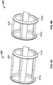
- FIGS. 7A-7B illustrate a cutaway of another alternative embodiment of a bladder ring assembly, with the rings in extended and compressed positions, respectively;
- FIGS. 8A-8B illustrate a cutaway of another alternative embodiment of a bladder ring assembly, with the rings in extended and compressed positions, respectively.
- Axial and “axially” refer to a direction that is parallel to the axis of rotation of a tire.
- “Circumferential” and “circumferentially” refer to a direction extending along the perimeter of the surface of the tread perpendicular to the axial direction.
- Ring and radially refer to a direction perpendicular to the axis of rotation of a tire.
- FIGS. 1A and 1B show a cutaway of an exemplary prior art embodiment of a bladder ring assembly 100 for a tire mold.
- the bladder ring assembly 100 includes a flexible bladder 110 having a first end connected to a first bladder ring 120 a and a second end connected to a second bladder ring 120 b .
- the first and second bladder rings 120 a,b are disposed about a center post (not shown), and are configured to be moved with respect to each other along the center post.
- the first bladder ring 120 a is fixed with respect to the center post, and only the second bladder ring 120 b translates along the center post.
- both the first and second bladder rings 120 a,b translate along the center post.
- first and second rings 120 a,b move relative to each other between an axially extended position in which the first ring is distal from the second ring (as shown in FIG. 1A ) and an axially compressed position in which the first ring is proximate to the second ring (as shown in FIG. 1B ).
- the bladder ring assembly 100 When the bladder ring assembly 100 is in the axially extended position, vacuum pressure may be applied to the interior of the bladder 110 to reduce the diameter of the bladder. The vacuum pressure may cause lobes 130 to form on the surface of the bladder 110 , with adjacent lobes 130 being separated by a valley 140 .
- the bladder ring assembly 100 When the bladder ring assembly 100 is in the axially extended position, it is configured to receive a green tire (not shown). After the green tire is disposed about the bladder 110 , the first and second bladder rings 120 a,b are moved to the axially compressed position so that the bladder 110 is axially contracted to be disposed within a cavity of the green tire. A hot pressure medium such as steam is then pressure injected into the bladder 110 , thereby further expanding the bladder 110 in a radial direction.
- FIGS. 2A and 2B show a cutaway of one embodiment of a bladder ring assembly 200 for a tire mold.
- the bladder ring assembly 200 includes a flexible bladder 210 having a first end connected to a first bladder ring 220 a and a second end connected to a second bladder ring 220 b .
- the first bladder ring 210 a has a first annular portion 230 a with a first diameter D 1 and a first axial length L 1 .
- the second bladder ring 210 b has a second annular portion 230 b with a second diameter D 2 and a second axial length L 2 .
- each of the first and second annular portions 230 a,b includes a plurality of ridges 240 that run circumferentially along an external surface of the annular portion.
- the first and second annular portions 230 a,b are solid portions.
- the first and second annular portions may include a plurality of apertures.
- the first diameter D 1 is equal to the second diameter D 2 .
- the first axial length L 1 is also equal to the second axial length L 1 .
- the first axial length is different from the second axial length.
- the first and second diameters D 1 , D 2 are between 16 to 22 inches (40 to 55 centimeters). In other embodiments, the first and second diameters D 1 , D 2 may be between 4 to 80 inches (10 to 200 centimeters). Additionally, in one known embodiment, the first and second axial lengths L 1 , L 2 are between 2 to 8 inches (5 to 20 centimeters).
- the first and second axial lengths L 1 , L 2 may be between 2 to 60 inches (5 to 150 centimeters). In one embodiment, a ratio of the first diameter D 1 to the first axial length L 1 is less than 4:1, and a ratio of the second diameter D 2 to the second axial length L 2 is likewise less than 4:1. In other words, D 1 ⁇ 4 ⁇ L 1 and D 2 ⁇ 4 ⁇ L 2 .
- the first and second bladder rings 220 a,b are disposed about a center post (not shown), and are configured to be moved with respect to each other along the center post.
- the first bladder ring 220 a is fixed with respect to the center post, and only the second bladder ring 220 b translates along the center post.
- both the first and second bladder rings 220 a,b translate along the center post.
- the first and second rings 220 a,b move relative to each other between an axially extended position in which the first ring is distal from the second ring (as shown in FIG. 2A ) and an axially compressed position in which the first ring is proximate to the second ring (as shown in FIG. 2B ).
- the bladder 210 When the bladder ring assembly 200 is in the axially extended position, the bladder 210 is stretched to a maximum axial length and the first bladder ring 220 a is separated from the second bladder ring 220 b by a gap G.
- the sum of the first axial length L 1 and second axial length L 2 is greater than the gap G.
- the sum of the first axial length L 1 and second axial length L 2 is approximately 1.5 times greater than the gap G.
- the sum of the first axial length L 1 and second axial length L 2 ranges from 0.5 times the gap G to 5 times the gap G.
- the first axial length L 1 is at least 40% of the maximum axial length of the bladder 210 and the second axial length L 2 is also at least 40% of the maximum axial length of the bladder 210 .
- first and second bladder rings 220 a,b when the first and second bladder rings 220 a,b are in the axially compressed position, they are still separated by a small gap.
- the first bladder ring contacts the second bladder ring in the axially compressed position.
- the bladder ring assembly 200 When the bladder ring assembly 200 is in the axially extended position, vacuum pressure is applied to the interior of the bladder 210 to reduce the diameter of the bladder.
- the vacuum pressure causes lobes 250 to form on the surface of the bladder 210 , with adjacent lobes 250 being separated by a valley 260 .
- the axial lengths and the external annular surfaces of the bladder rings 220 a , 220 b may be selected to reduce the number of lobes 250 that are formed in the bladder 210 .
- the axial lengths and the external annular surfaces of the bladder rings 220 a , 220 b may also be selected to reduce the depths of the valleys 260 that are formed in the bladder 210 .
- the axial lengths and the external annular surfaces of the bladder rings 220 a , 220 b may also be selected to reduce the amount of strain on the first and second ends of the bladder 210 .
- FIG. 3 shows a perspective view of a tire mold 300 with the bladder ring assembly 200 in the axially extended position.
- the tire mold 300 includes a vacuum (not shown) that applies vacuum pressure to the inside of the bladder ring assembly 200 .
- the bladder ring assembly 200 is configured to receive a green tire T in a tire cavity defined by the interior surfaces of the tire mold 300 .
- the first and second bladder rings are moved to the axially compressed position so that the bladder is axially contracted to be disposed within a cavity of the green tire T.
- the tire mold 300 further includes a hot pressure medium supply (not shown), that injects a hot pressure medium such as steam into the bladder ring assembly 200 when the bladder ring assembly is in the axially compressed position.
- a hot pressure medium such as steam
- the injection of the hot pressure medium expands the bladder in a radial direction, thereby pressing the green tire T into an internal surface of the tire mold 300 .
- FIG. 4 illustrates a cutaway of an alternative embodiment of bladder rings 400 a,b .
- the bladder rings 400 a,b are substantially the same as the bladder rings 220 a,b described above with reference to FIGS. 2A-2B except for the differences described herein.
- Each of the bladder rings 400 a,b has an outer, circular end and an inner end having a plurality of arches.
- the resulting geometry is a substantially cylindrical shape with undulating waves disposed about the annular surface.
- the bladder rings 400 a,b are arranged such that the arches of the opposing rings are offset.
- the bladder rings 400 a,b are arranged such that the arches of the opposing rings are aligned.
- the bladder rings 400 a,b may be rotated with respect to each other to be aligned at a desired orientation.
- FIG. 5 shows a cutaway of an alternative embodiment of bladder rings 500 a,b .
- the bladder rings 500 a,b are substantially the same as the bladder rings 220 a,b , and 400 a,b described above with reference to FIGS. 2A-2B, and 4 except for the differences described herein.
- Each of the bladder rings 500 a,b has an outer, circular end.
- a first bladder ring 500 a has an inner end having a plurality of arches
- a second bladder ring 500 b has a circular, inner end.
- both bladder rings have circular inner and outer rings.
- one or more additional bladder rings are disposed between the first and second bladder rings.
- the bladder rings may include a plurality of telescoping tubes.
- FIGS. 6A-6B show a cutaway of an alternative embodiment of a bladder ring assembly 600 , with the rings in extended and compressed positions.
- the bladder ring assembly 600 is substantially the same as the bladder ring assembly 200 described above with reference to FIGS. 2A-2B except for the differences described herein.
- the bladder ring assembly 600 includes a first bladder ring 610 a and a second bladder ring 610 b , each having an annular surface formed by a plurality of discrete portions 620 .
- Each of the discrete portions has a curved end, and therefore has a plurality of axial lengths.
- the axial length of the bladder rings 610 a,b is defined by the maximum axial length of the discrete portions 620 .
- Each of the discrete portions 620 is hingedly connected to an outer end of one of the rings 610 a,b .
- the discrete portions 620 extend in a substantially axial direction.
- the discrete portions 620 of the opposing rings contact each other.
- the discrete portions 620 of the opposing rings bias each other towards a radially outward position. Therefore, the discrete portions 620 may be referred to as articulating portions.
- the discrete portions 620 of opposing rings are offset such that the maximum axial length of one discrete portion is aligned with a minimum axial length of the opposing discrete portion.
- any orientation of the bladder rings may be employed.
- FIGS. 7A-7B show a cutaway of another alternative embodiment of a bladder ring assembly 700 , with the rings in extended and compressed positions.
- the bladder ring assembly 700 is substantially the same as the bladder ring assembly 200 described above with reference to FIGS. 2A-2B except for the differences described herein.
- the bladder ring assembly 700 includes a first bladder ring 710 a and a second bladder ring 710 b , each having an annular surface with a plurality of axial lengths. However, it should be understood that the axial length of the bladder rings 710 a,b is defined by the maximum axial length of each ring.
- the opposing bladder rings 710 a,b are offset such that the maximum axial length of a first ring 710 a is aligned with a minimum axial length of a second ring 710 b .
- finger-like protrusions define the plurality of axial lengths.
- the plurality of axial lengths may be defined by a wavy surface or other geometry.
- FIGS. 8A-8B show a cutaway of another alternative embodiment of a bladder ring assembly 800 , with the rings in extended and compressed positions.
- the bladder ring assembly 800 is substantially the same as the bladder ring assembly 200 described above with reference to FIGS. 2A-2B except for the differences described herein.
- the bladder ring assembly 800 includes a first bladder ring 810 a and a second bladder ring 810 b , with a plurality of telescoping arms 820 extending there-between. In the illustrated embodiment, five telescoping arms are employed. In an alternative embodiment (not shown), two, three, or four telescoping arms are employed. In another alternative embodiment (not shown), six or more telescoping arms are employed. The number of telescoping arms may be selected according to the size of the bladder rings. For example, it may be desirable to have more telescoping arms around larger bladder rings.
- the telescoping arms 820 are substantially cylindrical tubes including a large diameter portion that receives a small diameter portion. While only two pieces are illustrated for each telescoping arm, it should be understood that three or more telescoping pieces may be nested inside the telescoping arms. In one known embodiment, the telescoping arms include three to six nested pieces. However, it should be understood that any number of nested pieces may be employed.
- the diameter of the telescoping arms may be selected according to the size of the bladder rings 810 .
- the cross-sections of the telescoping arms may be square, rectangular, pentagonal, hexagonal, oval, or any other geometric shape.
- the telescoping arms may have open geometries.
- the telescoping arms may be C-shaped or L-shaped, or even have a planar geometry.
- each telescoping arm 820 is attached to the first bladder ring 810 a and a second end of the telescoping arm is attached to the second bladder ring 810 b .
- the telescoping arms 820 are in a compressed state when the bladder rings 810 a,b are in the compressed position, and the telescoping arms 820 are pulled into an extended state when the bladder rings 810 a,b are moved to an extended state.
- each telescoping arm 820 is attached to the first bladder ring 810 a , but second end of the telescoping arm is left free.
- the first bladder ring 810 a is an upper ring that is above the second bladder ring 810 b , and when the bladder rings 810 a,b move to an extended position, gravity causes the telescoping arms to extend downwards.
- the telescoping arms are mounted to rotatable rings that are mounted to the bladder rings.
- the rotatable rings may be rotated after a predetermined number of uses. Rotating in this manner may prevent the bladder from repeated stresses in the same locations.
- the telescoping arms may be replaced with folding arms.
- folding arms may be constructed of a flexible material.
- the folding arms may be constructed of a plurality of rigid members that are hingedly connected.
Abstract
Description
Claims (8)
Priority Applications (1)
| Application Number | Priority Date | Filing Date | Title |
|---|---|---|---|
| US15/737,844 US10632699B2 (en) | 2015-06-25 | 2016-06-27 | Bladder rings for tire vulcanization mold |
Applications Claiming Priority (3)
| Application Number | Priority Date | Filing Date | Title |
|---|---|---|---|
| US201562184299P | 2015-06-25 | 2015-06-25 | |
| US15/737,844 US10632699B2 (en) | 2015-06-25 | 2016-06-27 | Bladder rings for tire vulcanization mold |
| PCT/US2016/039535 WO2016210406A1 (en) | 2015-06-25 | 2016-06-27 | Bladder rings for tire vulcanization mold |
Publications (2)
| Publication Number | Publication Date |
|---|---|
| US20190001599A1 US20190001599A1 (en) | 2019-01-03 |
| US10632699B2 true US10632699B2 (en) | 2020-04-28 |
Family
ID=57586714
Family Applications (1)
| Application Number | Title | Priority Date | Filing Date |
|---|---|---|---|
| US15/737,844 Active 2036-09-29 US10632699B2 (en) | 2015-06-25 | 2016-06-27 | Bladder rings for tire vulcanization mold |
Country Status (3)
| Country | Link |
|---|---|
| US (1) | US10632699B2 (en) |
| EP (1) | EP3313653B1 (en) |
| WO (1) | WO2016210406A1 (en) |
Families Citing this family (2)
| Publication number | Priority date | Publication date | Assignee | Title |
|---|---|---|---|---|
| DE102021205427A1 (en) | 2020-06-05 | 2021-12-09 | Continental Reifen Deutschland Gmbh | Apparatus for assembling heating bladders for the vulcanization of tires and methods therefor |
| EP4209336A1 (en) * | 2022-01-11 | 2023-07-12 | Siemens Aktiengesellschaft | Heating bellows device for a tyre heating press device for vulcanising a vehicle tyre |
Citations (36)
| Publication number | Priority date | Publication date | Assignee | Title |
|---|---|---|---|---|
| US2736059A (en) * | 1956-02-28 | Tire curing press | ||
| US2880454A (en) | 1953-08-31 | 1959-04-07 | James W Brundage | Tire shaping device |
| US3640653A (en) | 1970-06-29 | 1972-02-08 | Nrm Corp | Tire curing press |
| US3712769A (en) | 1971-06-03 | 1973-01-23 | Goodrich Co B F | Fire loading apparatus with preheating device for green tires |
| US3902831A (en) | 1971-11-26 | 1975-09-02 | Bridgestone Tire Co Ltd | Device for removing a cured tire from a curing mold |
| US4608219A (en) | 1985-06-11 | 1986-08-26 | Nrm Corporation | Tire press, loader and method |
| US4670209A (en) | 1985-03-26 | 1987-06-02 | Kabushiki Kaisha Kobe Seiko Sho | Vulcanizing method for a tire press |
| US4877469A (en) | 1987-03-18 | 1989-10-31 | The Armstrong Rubber Company | Reinforced tire curing bladder and method for using same |
| EP0489268A1 (en) | 1990-12-06 | 1992-06-10 | Compagnie Generale Des Etablissements Michelin-Michelin & Cie | Turn-over device for tyrebuilding drum |
| US5165939A (en) | 1990-05-29 | 1992-11-24 | Pirelli Coordinamento Pneumatici S.P.A. | Vulcanization press having two molds operated separately from each other, in particular for vehicle tires |
| US6217307B1 (en) * | 1999-04-12 | 2001-04-17 | Pirelli Tire Llc | Spring spacer for bladder assembly in a tire curing press |
| US6363989B1 (en) | 1999-02-02 | 2002-04-02 | Pirelli Pneumatici S.P.A. | Anti-tack bladder |
| US6416305B1 (en) | 1998-10-26 | 2002-07-09 | Mcneil & Nrm, Inc. | Tire curing press center mechanism |
| US6620367B1 (en) | 1999-08-17 | 2003-09-16 | Kabushiki Kaisha Kobe Seiko Sho (Kobe Steel, Ltd.) | Tire vulcanizing method and tire vulcanizer |
| EP1398183A1 (en) | 2001-05-29 | 2004-03-17 | Bridgestone Corporation | REINFORCED AIR BLADDER FOR SAFETY TIRE,METHOD OF MANUFACTURING THE AIR BLADDER, AND METHOD OF MANUFACTURING REINFORCED LAYER FORMED BODY |
| US6770229B2 (en) | 2001-12-07 | 2004-08-03 | John R. Cole | Method for relieving pressure in newly vulcanized tires while still in the tire press |
| US6908584B2 (en) | 2002-08-16 | 2005-06-21 | John R. Cole | Apparatus and method for locking a tire vulcanizing press |
| JP2006150678A (en) | 2004-11-26 | 2006-06-15 | Yokohama Rubber Co Ltd:The | Tire vulcanizing apparatus |
| JP2006231615A (en) | 2005-02-23 | 2006-09-07 | Yokohama Rubber Co Ltd:The | Bladder for tire vulcanization and its manufacturing method |
| JP2007076268A (en) | 2005-09-16 | 2007-03-29 | Yokohama Rubber Co Ltd:The | Tire vulcanizer |
| US7281916B2 (en) | 2001-08-10 | 2007-10-16 | Bridgestone Corporation | Tire vulcanizing system and tire manufacturing method to be used therefor |
| JP2007331200A (en) | 2006-06-14 | 2007-12-27 | Yokohama Rubber Co Ltd:The | Tire vulcanizing apparatus |
| US20080084007A1 (en) | 2006-10-05 | 2008-04-10 | Carlisle Intangible Company | Low aspect ratio tire curing bladder |
| US20100032079A1 (en) * | 2006-12-06 | 2010-02-11 | Pirelli Tyre S.P.A. | Process and apparatus for manufacturing tyres |
| US7661944B2 (en) * | 2005-10-05 | 2010-02-16 | Ichimaru Giken Co., Ltd. | Tire vulcanizing device |
| US20100089520A1 (en) | 2008-10-13 | 2010-04-15 | The Goodyear Tire & Rubber Company | bladder, an apparatus and a method for shaping and curing a tire |
| WO2010128566A1 (en) | 2009-05-07 | 2010-11-11 | 横浜ゴム株式会社 | Method of manufacturing pneumatic tire |
| EP2289692A1 (en) | 2008-06-10 | 2011-03-02 | Bridgestone Corporation | Process for producing unvalcanized tire and apparatus for producing the tire |
| US7987697B2 (en) | 2008-07-14 | 2011-08-02 | Continental Tire North America, Inc. | Curing bladder leak detection system for a tire press |
| US8114335B2 (en) | 2002-12-30 | 2012-02-14 | The Goodyear Tire & Rubber Company | Partial depth-wise cure of a tire inner liner |
| JP2012086580A (en) | 2012-02-06 | 2012-05-10 | Sumitomo Rubber Ind Ltd | Method of manufacturing tire |
| JP5052335B2 (en) | 2005-03-03 | 2012-10-17 | 株式会社ブリヂストン | Manufacturing method and manufacturing device for pneumatic tire for safety tire |
| US20130087953A1 (en) | 2011-10-05 | 2013-04-11 | Michael Brendan Rodgers | Tire Curing Bladders |
| US8506276B2 (en) | 2010-04-23 | 2013-08-13 | The Yokohama Rubber Co., Ltd. | Method for manufacturing bladder for use in manufacturing tires |
| US8596322B2 (en) | 2010-12-10 | 2013-12-03 | The Goodyear Tire & Rubber Company | Tire support apparatus |
| WO2014099458A1 (en) | 2012-12-19 | 2014-06-26 | Bridgestone Americas Tire Operations, Llc | Method for producing tire-curing bladder |
Family Cites Families (3)
| Publication number | Priority date | Publication date | Assignee | Title |
|---|---|---|---|---|
| JP3999331B2 (en) * | 1998-02-25 | 2007-10-31 | 三菱重工業株式会社 | Tire vulcanization equipment |
| US6733712B2 (en) * | 2001-04-18 | 2004-05-11 | Pirelli Tire Llc | Extendable curing press center post |
| JP5474753B2 (en) * | 2010-12-21 | 2014-04-16 | 株式会社神戸製鋼所 | Central mechanism of tire vulcanizer |
-
2016
- 2016-06-27 EP EP16815481.3A patent/EP3313653B1/en active Active
- 2016-06-27 US US15/737,844 patent/US10632699B2/en active Active
- 2016-06-27 WO PCT/US2016/039535 patent/WO2016210406A1/en active Application Filing
Patent Citations (36)
| Publication number | Priority date | Publication date | Assignee | Title |
|---|---|---|---|---|
| US2736059A (en) * | 1956-02-28 | Tire curing press | ||
| US2880454A (en) | 1953-08-31 | 1959-04-07 | James W Brundage | Tire shaping device |
| US3640653A (en) | 1970-06-29 | 1972-02-08 | Nrm Corp | Tire curing press |
| US3712769A (en) | 1971-06-03 | 1973-01-23 | Goodrich Co B F | Fire loading apparatus with preheating device for green tires |
| US3902831A (en) | 1971-11-26 | 1975-09-02 | Bridgestone Tire Co Ltd | Device for removing a cured tire from a curing mold |
| US4670209A (en) | 1985-03-26 | 1987-06-02 | Kabushiki Kaisha Kobe Seiko Sho | Vulcanizing method for a tire press |
| US4608219A (en) | 1985-06-11 | 1986-08-26 | Nrm Corporation | Tire press, loader and method |
| US4877469A (en) | 1987-03-18 | 1989-10-31 | The Armstrong Rubber Company | Reinforced tire curing bladder and method for using same |
| US5165939A (en) | 1990-05-29 | 1992-11-24 | Pirelli Coordinamento Pneumatici S.P.A. | Vulcanization press having two molds operated separately from each other, in particular for vehicle tires |
| EP0489268A1 (en) | 1990-12-06 | 1992-06-10 | Compagnie Generale Des Etablissements Michelin-Michelin & Cie | Turn-over device for tyrebuilding drum |
| US6416305B1 (en) | 1998-10-26 | 2002-07-09 | Mcneil & Nrm, Inc. | Tire curing press center mechanism |
| US6363989B1 (en) | 1999-02-02 | 2002-04-02 | Pirelli Pneumatici S.P.A. | Anti-tack bladder |
| US6217307B1 (en) * | 1999-04-12 | 2001-04-17 | Pirelli Tire Llc | Spring spacer for bladder assembly in a tire curing press |
| US6620367B1 (en) | 1999-08-17 | 2003-09-16 | Kabushiki Kaisha Kobe Seiko Sho (Kobe Steel, Ltd.) | Tire vulcanizing method and tire vulcanizer |
| EP1398183A1 (en) | 2001-05-29 | 2004-03-17 | Bridgestone Corporation | REINFORCED AIR BLADDER FOR SAFETY TIRE,METHOD OF MANUFACTURING THE AIR BLADDER, AND METHOD OF MANUFACTURING REINFORCED LAYER FORMED BODY |
| US7281916B2 (en) | 2001-08-10 | 2007-10-16 | Bridgestone Corporation | Tire vulcanizing system and tire manufacturing method to be used therefor |
| US6770229B2 (en) | 2001-12-07 | 2004-08-03 | John R. Cole | Method for relieving pressure in newly vulcanized tires while still in the tire press |
| US6908584B2 (en) | 2002-08-16 | 2005-06-21 | John R. Cole | Apparatus and method for locking a tire vulcanizing press |
| US8114335B2 (en) | 2002-12-30 | 2012-02-14 | The Goodyear Tire & Rubber Company | Partial depth-wise cure of a tire inner liner |
| JP2006150678A (en) | 2004-11-26 | 2006-06-15 | Yokohama Rubber Co Ltd:The | Tire vulcanizing apparatus |
| JP2006231615A (en) | 2005-02-23 | 2006-09-07 | Yokohama Rubber Co Ltd:The | Bladder for tire vulcanization and its manufacturing method |
| JP5052335B2 (en) | 2005-03-03 | 2012-10-17 | 株式会社ブリヂストン | Manufacturing method and manufacturing device for pneumatic tire for safety tire |
| JP2007076268A (en) | 2005-09-16 | 2007-03-29 | Yokohama Rubber Co Ltd:The | Tire vulcanizer |
| US7661944B2 (en) * | 2005-10-05 | 2010-02-16 | Ichimaru Giken Co., Ltd. | Tire vulcanizing device |
| JP2007331200A (en) | 2006-06-14 | 2007-12-27 | Yokohama Rubber Co Ltd:The | Tire vulcanizing apparatus |
| US20080084007A1 (en) | 2006-10-05 | 2008-04-10 | Carlisle Intangible Company | Low aspect ratio tire curing bladder |
| US20100032079A1 (en) * | 2006-12-06 | 2010-02-11 | Pirelli Tyre S.P.A. | Process and apparatus for manufacturing tyres |
| EP2289692A1 (en) | 2008-06-10 | 2011-03-02 | Bridgestone Corporation | Process for producing unvalcanized tire and apparatus for producing the tire |
| US7987697B2 (en) | 2008-07-14 | 2011-08-02 | Continental Tire North America, Inc. | Curing bladder leak detection system for a tire press |
| US20100089520A1 (en) | 2008-10-13 | 2010-04-15 | The Goodyear Tire & Rubber Company | bladder, an apparatus and a method for shaping and curing a tire |
| WO2010128566A1 (en) | 2009-05-07 | 2010-11-11 | 横浜ゴム株式会社 | Method of manufacturing pneumatic tire |
| US8506276B2 (en) | 2010-04-23 | 2013-08-13 | The Yokohama Rubber Co., Ltd. | Method for manufacturing bladder for use in manufacturing tires |
| US8596322B2 (en) | 2010-12-10 | 2013-12-03 | The Goodyear Tire & Rubber Company | Tire support apparatus |
| US20130087953A1 (en) | 2011-10-05 | 2013-04-11 | Michael Brendan Rodgers | Tire Curing Bladders |
| JP2012086580A (en) | 2012-02-06 | 2012-05-10 | Sumitomo Rubber Ind Ltd | Method of manufacturing tire |
| WO2014099458A1 (en) | 2012-12-19 | 2014-06-26 | Bridgestone Americas Tire Operations, Llc | Method for producing tire-curing bladder |
Non-Patent Citations (3)
| Title |
|---|
| AMCL Machinery Ltd.; Tyre Curing Presses: Aubo Range; URL: http://www.amcl.in/images/products/downloads/aubo%20range.pdf. The year of publication is sufficiently earlier than the effective U.S. filing date and any foreign priority date. MPEP 609.04(a). |
| International Search Report and Written Opinion; corresponding PCT Application No. PCT/US2016/039535; filed Jun. 27, 2016; Authorized Officer Kang; dated Sep. 30, 2016. |
| Rockwell Automation; Tire Building Machine: Reduce Design Time and Improve TCO for Tire Manufacturers; URL: http://literature.rockwellautomation.com/idc/groups/literature/documents/wp/tire-wp002_-en-p.pdf; 2013. The year of publication is sufficiently earlier than the effective U.S. filing date and any foreign priority date. MPEP 609.04 (a). |
Also Published As
| Publication number | Publication date |
|---|---|
| EP3313653A1 (en) | 2018-05-02 |
| WO2016210406A1 (en) | 2016-12-29 |
| EP3313653A4 (en) | 2019-04-10 |
| EP3313653B1 (en) | 2020-05-06 |
| US20190001599A1 (en) | 2019-01-03 |
Similar Documents
| Publication | Publication Date | Title |
|---|---|---|
| US3035629A (en) | Tire building apparatus and method | |
| US20130008611A1 (en) | Multi-Piece Sealing Sleeve | |
| US7491285B2 (en) | Method for molding bead portion of green tire and bead portion molding device | |
| EP3037249A1 (en) | Sleeveless tire building drum | |
| SK155299A3 (en) | Tyre building drum with turn-up apparatus | |
| EP2698243B1 (en) | Sleeveless tire building drum | |
| US10632699B2 (en) | Bladder rings for tire vulcanization mold | |
| CN104619465B (en) | Assembly method and assembling device | |
| BR102014025896B1 (en) | drum for tire construction | |
| DE602005009958D1 (en) | REVENTROMMELANELUNGNUNG WITH ENVELOPING MECHANISMS FOR CONSTRUCTION OF UNVULKANIZED TIRE | |
| JPS6253342B2 (en) | ||
| EP2698244B1 (en) | Sleeveless tire building drum with interchangeable width elements | |
| JP2006168367A (en) | Bead fixing segment interlaced for tire manufacturing drum | |
| NL2020768B1 (en) | Tire building drum and turn-up method | |
| JP4754668B2 (en) | Tire building drum | |
| US3281305A (en) | Tire building drum variable in diameter | |
| US4060445A (en) | Building drum for tires and cylindrical articles having axially spaced beads | |
| KR20120073624A (en) | Sleeve for mandrel advanced durable | |
| JP6933928B2 (en) | Central mechanism for tire assembly drum | |
| JPS5917945B2 (en) | Air spring molding device | |
| JP2009196191A (en) | Method and mechanism of locking bead core | |
| BR0107380A (en) | Mounting drum for tire manufacturing | |
| CN106457713A (en) | Process and apparatus for building tyres | |
| CN209971620U (en) | Turning-up device for a tyre building drum and tyre building drum | |
| JP6848692B2 (en) | Molding drum |
Legal Events
| Date | Code | Title | Description |
|---|---|---|---|
| AS | Assignment |
Owner name: BRIDGESTONE AMERICAS TIRE OPERATIONS, LLC, TENNESSEE Free format text: ASSIGNMENT OF ASSIGNORS INTEREST;ASSIGNORS:ASPER, ROBERT W.;NESBITT, ADAM K.;BARR, JASON R.;AND OTHERS;SIGNING DATES FROM 20150709 TO 20150812;REEL/FRAME:044431/0795 Owner name: BRIDGESTONE AMERICAS TIRE OPERATIONS, LLC, TENNESS Free format text: ASSIGNMENT OF ASSIGNORS INTEREST;ASSIGNORS:ASPER, ROBERT W.;NESBITT, ADAM K.;BARR, JASON R.;AND OTHERS;SIGNING DATES FROM 20150709 TO 20150812;REEL/FRAME:044431/0795 |
|
| FEPP | Fee payment procedure |
Free format text: ENTITY STATUS SET TO UNDISCOUNTED (ORIGINAL EVENT CODE: BIG.); ENTITY STATUS OF PATENT OWNER: LARGE ENTITY |
|
| AS | Assignment |
Owner name: BRIDGESTONE AMERICAS TIRE OPERATIONS, LLC, TENNESSEE Free format text: ASSIGNMENT OF ASSIGNORS INTEREST;ASSIGNOR:KIM, HYEONJAE;REEL/FRAME:044973/0420 Effective date: 20180216 Owner name: BRIDGESTONE AMERICAS TIRE OPERATIONS, LLC, TENNESS Free format text: ASSIGNMENT OF ASSIGNORS INTEREST;ASSIGNOR:KIM, HYEONJAE;REEL/FRAME:044973/0420 Effective date: 20180216 |
|
| STPP | Information on status: patent application and granting procedure in general |
Free format text: DOCKETED NEW CASE - READY FOR EXAMINATION |
|
| STPP | Information on status: patent application and granting procedure in general |
Free format text: NON FINAL ACTION MAILED |
|
| STPP | Information on status: patent application and granting procedure in general |
Free format text: RESPONSE TO NON-FINAL OFFICE ACTION ENTERED AND FORWARDED TO EXAMINER |
|
| STPP | Information on status: patent application and granting procedure in general |
Free format text: FINAL REJECTION MAILED |
|
| STPP | Information on status: patent application and granting procedure in general |
Free format text: DOCKETED NEW CASE - READY FOR EXAMINATION |
|
| STPP | Information on status: patent application and granting procedure in general |
Free format text: NOTICE OF ALLOWANCE MAILED -- APPLICATION RECEIVED IN OFFICE OF PUBLICATIONS |
|
| STCF | Information on status: patent grant |
Free format text: PATENTED CASE |
|
| FEPP | Fee payment procedure |
Free format text: MAINTENANCE FEE REMINDER MAILED (ORIGINAL EVENT CODE: REM.); ENTITY STATUS OF PATENT OWNER: LARGE ENTITY |