EP1398144B1 - Laminated trim element - Google Patents
Laminated trim element Download PDFInfo
- Publication number
- EP1398144B1 EP1398144B1 EP03019639A EP03019639A EP1398144B1 EP 1398144 B1 EP1398144 B1 EP 1398144B1 EP 03019639 A EP03019639 A EP 03019639A EP 03019639 A EP03019639 A EP 03019639A EP 1398144 B1 EP1398144 B1 EP 1398144B1
- Authority
- EP
- European Patent Office
- Prior art keywords
- element according
- recesses
- core part
- trim element
- trim
- Prior art date
- Legal status (The legal status is an assumption and is not a legal conclusion. Google has not performed a legal analysis and makes no representation as to the accuracy of the status listed.)
- Expired - Lifetime
Links
- 239000000853 adhesive Substances 0.000 claims abstract description 34
- 230000001070 adhesive effect Effects 0.000 claims abstract description 34
- 239000004033 plastic Substances 0.000 claims description 8
- 229920003023 plastic Polymers 0.000 claims description 8
- 238000010030 laminating Methods 0.000 claims description 7
- 239000002023 wood Substances 0.000 claims description 7
- 239000000463 material Substances 0.000 claims description 6
- 239000002184 metal Substances 0.000 claims description 5
- 229920000049 Carbon (fiber) Polymers 0.000 claims description 4
- 239000004917 carbon fiber Substances 0.000 claims description 4
- 238000009827 uniform distribution Methods 0.000 claims description 4
- VNWKTOKETHGBQD-UHFFFAOYSA-N methane Chemical compound C VNWKTOKETHGBQD-UHFFFAOYSA-N 0.000 claims description 3
- 238000003475 lamination Methods 0.000 description 16
- 238000004519 manufacturing process Methods 0.000 description 5
- 238000000034 method Methods 0.000 description 3
- 150000001875 compounds Chemical class 0.000 description 2
- 238000009826 distribution Methods 0.000 description 2
- 238000005516 engineering process Methods 0.000 description 2
- 239000000758 substrate Substances 0.000 description 2
- 239000011324 bead Substances 0.000 description 1
- 239000003795 chemical substances by application Substances 0.000 description 1
- 238000010276 construction Methods 0.000 description 1
- 238000007796 conventional method Methods 0.000 description 1
- 230000001419 dependent effect Effects 0.000 description 1
- 238000001035 drying Methods 0.000 description 1
- 230000004313 glare Effects 0.000 description 1
- 238000002347 injection Methods 0.000 description 1
- 239000007924 injection Substances 0.000 description 1
- 230000007246 mechanism Effects 0.000 description 1
- 238000003801 milling Methods 0.000 description 1
- 238000000465 moulding Methods 0.000 description 1
- 235000011837 pasties Nutrition 0.000 description 1
- 238000007493 shaping process Methods 0.000 description 1
- 239000000243 solution Substances 0.000 description 1
- 238000004381 surface treatment Methods 0.000 description 1
- 230000000007 visual effect Effects 0.000 description 1
- 238000003466 welding Methods 0.000 description 1
Images


Classifications
-
- B—PERFORMING OPERATIONS; TRANSPORTING
- B32—LAYERED PRODUCTS
- B32B—LAYERED PRODUCTS, i.e. PRODUCTS BUILT-UP OF STRATA OF FLAT OR NON-FLAT, e.g. CELLULAR OR HONEYCOMB, FORM
- B32B3/00—Layered products comprising a layer with external or internal discontinuities or unevennesses, or a layer of non-planar form; Layered products having particular features of form
- B32B3/26—Layered products comprising a layer with external or internal discontinuities or unevennesses, or a layer of non-planar form; Layered products having particular features of form characterised by a particular shape of the outline of the cross-section of a continuous layer; characterised by a layer with cavities or internal voids ; characterised by an apertured layer
- B32B3/30—Layered products comprising a layer with external or internal discontinuities or unevennesses, or a layer of non-planar form; Layered products having particular features of form characterised by a particular shape of the outline of the cross-section of a continuous layer; characterised by a layer with cavities or internal voids ; characterised by an apertured layer characterised by a layer formed with recesses or projections, e.g. hollows, grooves, protuberances, ribs
-
- B—PERFORMING OPERATIONS; TRANSPORTING
- B32—LAYERED PRODUCTS
- B32B—LAYERED PRODUCTS, i.e. PRODUCTS BUILT-UP OF STRATA OF FLAT OR NON-FLAT, e.g. CELLULAR OR HONEYCOMB, FORM
- B32B15/00—Layered products comprising a layer of metal
- B32B15/04—Layered products comprising a layer of metal comprising metal as the main or only constituent of a layer, which is next to another layer of the same or of a different material
- B32B15/08—Layered products comprising a layer of metal comprising metal as the main or only constituent of a layer, which is next to another layer of the same or of a different material of synthetic resin
-
- B—PERFORMING OPERATIONS; TRANSPORTING
- B32—LAYERED PRODUCTS
- B32B—LAYERED PRODUCTS, i.e. PRODUCTS BUILT-UP OF STRATA OF FLAT OR NON-FLAT, e.g. CELLULAR OR HONEYCOMB, FORM
- B32B21/00—Layered products comprising a layer of wood, e.g. wood board, veneer, wood particle board
- B32B21/04—Layered products comprising a layer of wood, e.g. wood board, veneer, wood particle board comprising wood as the main or only constituent of a layer, which is next to another layer of the same or of a different material
- B32B21/08—Layered products comprising a layer of wood, e.g. wood board, veneer, wood particle board comprising wood as the main or only constituent of a layer, which is next to another layer of the same or of a different material of synthetic resin
-
- B—PERFORMING OPERATIONS; TRANSPORTING
- B32—LAYERED PRODUCTS
- B32B—LAYERED PRODUCTS, i.e. PRODUCTS BUILT-UP OF STRATA OF FLAT OR NON-FLAT, e.g. CELLULAR OR HONEYCOMB, FORM
- B32B27/00—Layered products comprising a layer of synthetic resin
- B32B27/06—Layered products comprising a layer of synthetic resin as the main or only constituent of a layer, which is next to another layer of the same or of a different material
- B32B27/08—Layered products comprising a layer of synthetic resin as the main or only constituent of a layer, which is next to another layer of the same or of a different material of synthetic resin
-
- B—PERFORMING OPERATIONS; TRANSPORTING
- B32—LAYERED PRODUCTS
- B32B—LAYERED PRODUCTS, i.e. PRODUCTS BUILT-UP OF STRATA OF FLAT OR NON-FLAT, e.g. CELLULAR OR HONEYCOMB, FORM
- B32B27/00—Layered products comprising a layer of synthetic resin
- B32B27/12—Layered products comprising a layer of synthetic resin next to a fibrous or filamentary layer
-
- B—PERFORMING OPERATIONS; TRANSPORTING
- B32—LAYERED PRODUCTS
- B32B—LAYERED PRODUCTS, i.e. PRODUCTS BUILT-UP OF STRATA OF FLAT OR NON-FLAT, e.g. CELLULAR OR HONEYCOMB, FORM
- B32B37/00—Methods or apparatus for laminating, e.g. by curing or by ultrasonic bonding
- B32B37/12—Methods or apparatus for laminating, e.g. by curing or by ultrasonic bonding characterised by using adhesives
- B32B37/1284—Application of adhesive
-
- B—PERFORMING OPERATIONS; TRANSPORTING
- B32—LAYERED PRODUCTS
- B32B—LAYERED PRODUCTS, i.e. PRODUCTS BUILT-UP OF STRATA OF FLAT OR NON-FLAT, e.g. CELLULAR OR HONEYCOMB, FORM
- B32B2605/00—Vehicles
-
- B—PERFORMING OPERATIONS; TRANSPORTING
- B32—LAYERED PRODUCTS
- B32B—LAYERED PRODUCTS, i.e. PRODUCTS BUILT-UP OF STRATA OF FLAT OR NON-FLAT, e.g. CELLULAR OR HONEYCOMB, FORM
- B32B2605/00—Vehicles
- B32B2605/003—Interior finishings
-
- B—PERFORMING OPERATIONS; TRANSPORTING
- B60—VEHICLES IN GENERAL
- B60R—VEHICLES, VEHICLE FITTINGS, OR VEHICLE PARTS, NOT OTHERWISE PROVIDED FOR
- B60R13/00—Elements for body-finishing, identifying, or decorating; Arrangements or adaptations for advertising purposes
- B60R13/02—Internal Trim mouldings ; Internal Ledges; Wall liners for passenger compartments; Roof liners
Definitions
- the present invention relates to a laminated panel member, particularly to a panel member in which the adhesive used for laminating is distributed through channels.
- Core part and panel are joined together by lamination.
- an adhesive is applied to the surface of the core member after it has been inserted into a workpiece holder, and after placing the diaphragm, the pressure required for lamination is applied to the diaphragm by means of a lamination stamp, whereupon it is laminated to the core member by means of the adhesive.
- the adhesive is usually applied in the form of strips. This deviates when laminating to the side and should form a layer of the same thickness as possible between the core part and aperture. Often, however, the adhesive does not run evenly during lamination, so that unwanted bulges of the aperture disturb the visual impression.
- a surface treatment method is known in which the surface is roughened before the application of adhesive.
- the roughness, ie grooves, is preferably produced by photablation or electroerosion.
- the invention is based on the idea to achieve a uniform distribution of the adhesive between the panel and the core part.
- Lamination here is to be understood as the two-dimensional contacting of the underside of the diaphragm with the upper side of the core part carrying the depressions and channels.
- adhesive is meant any adhesive commonly used for lamination, especially those adhesives which must be used in volumes which may be unevenly distributed.
- the core part may be formed as a molded part, which is configured on the back so that it fits to the raw surface to be veneered. On the other hand, it must have as flat as possible recesses and channels surface, but may contain desired bulges or other shapes.
- the visor must also be smooth on its underside and either in shape to match the top of the core part or by its flexibility can be brought into the appropriate form during lamination.
- the recesses are connected to the channels with each other.
- the channels interconnect as many recesses with each other as to ensure uniform distribution of the adhesive between the recesses during lamination of the core member with shroud.
- the depressions can be arranged in a great variety of ways on the upper side of the core part. For example, they may be distributed empirically based on the surface configuration of the core part, or preferably arranged in rows and on these orthogonal columns on the surface of the core part. Also with respect to the running channels between wells are the designer a variety of options available. Thus, for example, the application of the adhesive can be taken into account and, in the case of strip-wise application of adhesive, a preferred direction for the distribution can be determined, in which more channels are arranged than in other directions. Also, after trial laminations, the tool used to make the core member may still be modified to add or remove channels. This can be done by milling away or welding on webs, which later stamp out the channels.
- the channels extend from recess to recess within each row and / or column.
- the wells of a row or a column are each connected together or compounds are made both between wells of a row and a column of each of the wells.
- the arrangement of the channels can be designed such that they run between each recess and the respectively directly adjacent recesses. In an orthogonal arrangement in rows and columns, this means, for example, that in the corners of the core part, the recesses with the three neighboring recesses, at the edges with the five neighboring recesses and in the central region of the surface of the core part, each recess with the eight adjacent recesses through channels can be.
- mixed forms and preferred directions can be determined, in which more or less channels are used.
- each recess is directly surrounded by six other recesses arranged in a uniform triangle around this recess.
- the channels between each recess may be in respectively directly adjacent recesses, i. in the case of rectangular depressions with two other depressions, in the case of marginal with three or five adjacent wells and in the case on the main surface of the core part befind Anlagen compounds with six other adjacent wells be connected by channels.
- the depressions may, for example, have a circular outline and be designed as hollow cylinders or lenticular or spherical depressions. Exactly so it is also possible other forms of depressions in the Floor plan to use, for example, hexagonal, instituteekkige or square.
- the depressions preferably have a depth of 0.1 to 1 mm, but the actual depth to be used depends on the area of the core part and the amount of adhesive applied during lamination.
- the depressions can have a mutual distance measured from center of depression to center of depression of 10 mm to 25 mm, whereby these distances also depend on the specific embodiment of embodiments according to the present invention, eg material thickness of the diaphragm, viscosity of the adhesive and other parameters.
- the channels may have a width of 2 to 5 mm, and a depth of 0.1 to 1.5 mm, wherein the specific dimensions of empirical values, the amount of adhesive used and the viscosity or the drying behavior of the adhesive can be influenced.
- the channels may preferably have a rectangular, dreiekkigen or round cross-section, which may depend in addition to the needs of distribution also on the available possibilities or advantages in the production of tools for the core part.
- the adhesive is preferably a pasty material which, during lamination of the core portion and aperture, is formed into a layer of substantially homogeneous thickness between the core portion and the aperture. Only a homogeneous thickness can prevent the occurrence of unwanted protrusions or dents in the aperture.
- the core part may further comprise at least one holder for fixing the diaphragm element on a substrate.
- Corresponding holding mechanisms are familiar to the person skilled in the art of glare technology and can be, for example, plug-in elements for receiving corresponding openings in the substrate.
- Such male members may be equipped with barbs or the like to prevent subsequent slippage after mounting the panel member on the ground.
- the diaphragm element is an aperture for a vehicle interior.
- the panel may for example consist of sheet metal, a plastic plate, carbon fibers, wood veneer or a laminate.
- Laminates for example of wood veneer and a soft sheet, have been developed to improve the splintering behavior of wood veneer.
- the core part may have an edge and the diaphragm may be led beyond the edge on at least one side of the core part and bent around it. In this way, the edge of the core part is no longer visible, but only the surface of the corresponding curved aperture.
- the core part may contain plastic or consist of plastic, for example, be a corresponding injection molded part.
- the present invention provides an aperture member which avoids the prior art aperture surface irregularities without complicating its manufacture.
- Fig. 1 schematically represents the elements required for lamination.
- the diaphragm element 1 consists of core element 10, aperture 20, in the present case a diaphragm plate, and caterpillar applied strips of adhesive 30, shown here in cross section.
- the sandwiched arrangement of these elements is compressed by means of a laminating ram 2 and a pressure applying ram 3.
- Not shown is also necessary for lamination workpiece holder into which the core member 10 is inserted.
- the core member 10 is in the present embodiment in addition to the actual, here curved element with recesses 11 and male members 12 with barbs 13, which may be designed so that they yield when inserted into an opening of a surface to be veneered and after passing through the opening in return their shape to form the barb.
- the panel 20 further has at least one, here shown at two, of their sides a bulge, which can extend around the side of the core part 10 around and this includes from all or some pages so that the user Core part can no longer perceive.
- the adhesive beads 30 are pressed flat and at least partially run into the depressions, where excess adhesive is absorbed.
- FIG Fig. 2 The surface of a core member according to a first embodiment of the invention is shown in FIG Fig. 2 shown.
- the depressions 11 are arranged on the surface of the core part 10 in rows 14 and columns 15.
- only recesses of the rows 14 are interconnected by channels 16, wherein emanate from each well 16 on the row 14 to the terminal wells two channels. A compensation of excess adhesive can therefore only take place in the direction of the rows 14 here.
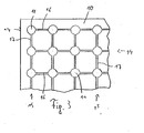
- Fig. 3 shows a further embodiment of a core part 10 only partially shown, in which in addition to the rows 14 through channels 16 and the columns 15 are interconnected by means of channels 17. Each recess thus has two channels to compensate for the running adhesive.
Abstract
Description
Die vorliegende Erfindung betrifft ein laminiertes Blendenelement, insbesondere betrifft sie ein Blendenelement, bei dem das zum Laminieren verwendete Klebemittel durch Kanäle verteilt wird.The present invention relates to a laminated panel member, particularly to a panel member in which the adhesive used for laminating is distributed through channels.
Die zunehmende Bedeutung guten Designs auch im industriellen Bereich erfordert in steigendem Maße komplexe Techniken zur Realisierung der gewünschten Oberfläche der neuen Objekte. Aufgrund der bei vielen Produkten notwendigen Konzessionen an die Gestaltung einer Oberfläche oder eines Gehäuses ist man in vielen Fällen dazu übergegangen, den technisch bedingten notwendigen Unterbau von der eigentlichen Oberfläche zu trennen, und die Oberfläche in Form von Blenden dem Produkt hinzuzufügen.The increasing importance of good design also in the industrial sector requires increasingly complex techniques for realizing the desired surface of the new objects. Due to the necessary concessions for the design of a surface or a housing for many products In many cases, one has gone over to separate the technically necessary necessary substructure from the actual surface, and to add the surface in the form of panels to the product.
So sind beispielsweise im Automobilbau die meisten der im Innenraum verwendeten Formteile von komplexem Aufbau. Armaturentafel, Seitenverkleidungen und andere Teile müssen aus sicherheitstechnischen Gründen bestimmten Anforderungen genügen. Die Fertigung aus Kunststoffen führt jedoch häufig dazu, dass die Teile als solche unansehnlich sind. Daher bieten die Automobilhersteller serienmäßig oder als Ausstattungsvariante alternative Oberflächen statt der Standardkunststoffteile an. Diese bestehen zumeist aus sogenannten Zierblenden, die einen Oberflächeneindruck von verschiedenen Holz-, Metall- oder Kohlefasersorten erwecken. Aufgrund der häufig komplex gekrümmten Oberflächen ist es jedoch zumeist nicht einfach, die gewählten Materialien formgebend auf die Oberfläche aufzukleben oder sonstwie zu befestigen. Daher werden Zierblenden auf eine Unterbau bzw. einem Kern angeordnet, der hinsichtlich seiner Form an die Form der Zierblende angepasst ist. Diese Teile sind in einfacher Weise vorzufertigen und können als fertiges Montagestück im Werk aufgeclippt oder sonst wie befestigt werden, ohne dass ein großer Aufwand notwendig ist. Auch auf anderen Gebieten der Technik, wie beispielsweise bei Computerkomponenten oder Stereoanlagen, werden ähnliche Zierblenden verwendet, um einen vom Designer gewünschten Oberflächeneindruck zu erzielen. Auch hier sind häufig laminierte Blendenelemente gewünscht, die aus einem Kernteil und einer Blende bestehen. Die Blende kann je nach Einsatz aus unterschiedlichem Material bestehen und somit verschiedenartiges Design aufweisen. Als Material kann Metall, Holzfurnier oder Kunststoff gewählt werden. Im folgenden wird die Blende als Blendenplatte bezeichnet.For example, in automotive engineering, most of the moldings used in the interior are of complex construction. Dashboard, side panels and other parts must meet certain requirements for safety reasons. The production of plastics, however, often leads to the parts being unsightly as such. Therefore, the car manufacturers offer as standard or as equipment alternative surfaces instead of the standard plastic parts. These consist mostly of so-called decorative panels that create a surface impression of various types of wood, metal or carbon fiber. Due to the often complex curved surfaces, however, it is usually not easy to stick the selected materials shaping the surface or otherwise secure. Therefore, trim panels are placed on a base or a core, which is adapted in shape to the shape of the trim. These parts can be prefabricated in a simple manner and can be clipped as a finished piece of work at the factory or otherwise secured, without a great effort is necessary. Also in other fields of technology, such as computer components or stereos, similar trim panels are used to achieve a surface appearance desired by the designer. Again, laminated panel elements are often desired, which consist of a core part and a diaphragm. Depending on the use, the panel can be made of different materials and therefore different Design. As material metal, wood veneer or plastic can be chosen. In the following, the aperture is called aperture plate.
Kernteil und Blende werden miteinander durch Laminieren verbunden. Hierzu wird ein Klebstoff auf die Oberfläche des Kernteils aufgebracht, nachdem dieses in eine Werkstückhalterung eingesetzt worden ist, und nach Auflegen der Blende wird der zum Laminieren notwendige Druck mittels eines Laminierstempels auf die Blende aufgebracht, woraufhin diese mittels des Klebemittels mit dem Kernteil laminiert wird.Core part and panel are joined together by lamination. For this purpose, an adhesive is applied to the surface of the core member after it has been inserted into a workpiece holder, and after placing the diaphragm, the pressure required for lamination is applied to the diaphragm by means of a lamination stamp, whereupon it is laminated to the core member by means of the adhesive.
Aus fertigungstechnischen Gründen wird zumeist der Klebstoff in Form von Streifen aufgebracht. Dieser weicht beim Laminieren zur Seite aus und soll eine Schicht möglichst gleicher Dicke zwischen Kernteil und Blende bilden. Häufig jedoch verläuft der Klebstoff beim Laminieren nicht gleichmäßig, so dass unerwünschte Aufwölbungen der Blende den optischen Eindruck stören.For manufacturing reasons, the adhesive is usually applied in the form of strips. This deviates when laminating to the side and should form a layer of the same thickness as possible between the core part and aperture. Often, however, the adhesive does not run evenly during lamination, so that unwanted bulges of the aperture disturb the visual impression.
Aus der
Es ist daher die Aufgabe der vorliegenden Erfindung, ein Blendenelement bereit zu stellen, welches aufgrund der gleichmäßigen Verteilung des Klebemittels eine gleichmäßig gewölbte oder ebene Oberfläche hat, die den Designvorgaben entspricht.It is therefore the object of the present invention to provide an aperture element which, due to the uniform distribution of the adhesive, has a uniformly curved or flat surface which conforms to the design specifications.
Diese Aufgabe wird erfindungsgemäß gelöst durch die Bereitstellung eines laminierten Blendenelements gemäß dem unabhängigen Patentanspruch 1. Weitere vorteilhafte Ausgestaltungen und Details der vorliegenden Erfindung ergeben sich aus den abhängigen Patentansprüchen, der Beschreibung und den beigefügten Zeichnungen.This object is achieved according to the invention by providing a laminated panel element according to the
Der Erfindung liegt die Idee zugrunde, ein gleichmäßiges Verteilen des Klebstoffs zwischen der Blende und dem Kernteil zu erzielen.The invention is based on the idea to achieve a uniform distribution of the adhesive between the panel and the core part.
Die Erfindung ist daher gerichtet auf ein laminiertes Blendenelement, welches aufweist:
- ein Kernteil;
- ein auf dem Kern aufgebrachtes Klebemittel; und
- eine auf dem Kernteil positionierte, durch das Klebemittel mit dem Kernmittel laminierte Blende, wobei dieses Blendenelement dadurch gekennzeichnet ist, dass das Kernteil eine Anordnung einer Mehrzahl von Vertiefungen zur Aufnahme und Verteilung von Klebemittel während des Laminierens der Blende auf das Kernteil aufweist.
- a core part;
- an adhesive applied to the core; and
- a diaphragm positioned on the core member and laminated with the core agent by the adhesive, this diaphragm member characterized in that the core member has an array of a plurality of recesses for receiving and distributing adhesive during lamination of the diaphragm to the core member.
Unter Laminieren ist hierbei das flächige Inkontaktbringen der Unterseite der Blende mit der die Vertiefungen und Kanäle tragenden Oberseite des Kernteils zu verstehen. Unter einem Klebemittel ist jeglicher üblicherweise zum Laminieren verwendeter Klebstoff zu verstehen, insbesondere solche Klebstoffe, die in Volumina verwendet werden müssen, bei denen es zu einer ungleichmäßigen Verteilung kommen kann.Lamination here is to be understood as the two-dimensional contacting of the underside of the diaphragm with the upper side of the core part carrying the depressions and channels. By adhesive is meant any adhesive commonly used for lamination, especially those adhesives which must be used in volumes which may be unevenly distributed.
Der Kernteil kann als Formteil ausgebildet sein, welches auf der Rückseite so ausgestaltet ist, dass es zu der zu verblendenden Rohoberfläche passt. Auf der anderen Seite muss es eine bis auf Vertiefungen und Kanäle möglichst ebene Oberfläche aufweisen, die jedoch gewünschte Wölbungen oder andere Formen enthalten kann. Die Blende muss an ihrer Unterseite ebenfalls glatt und entweder in der Form passend zur Oberseite des Kernteils sein oder durch ihre Flexibilität beim Laminieren in die entsprechende Form gebracht werden können.The core part may be formed as a molded part, which is configured on the back so that it fits to the raw surface to be veneered. On the other hand, it must have as flat as possible recesses and channels surface, but may contain desired bulges or other shapes. The visor must also be smooth on its underside and either in shape to match the top of the core part or by its flexibility can be brought into the appropriate form during lamination.
Vorzugsweise sind die Vertiefungen mit den Kanälen untereinander verbunden. Vorzugsweise verbinden die Kanäle jeweils so viele Vertiefungen miteinander, dass ein gleichförmiges Verteilen des Klebemittels zwischen den Vertiefungen während des Laminierens von Kernteil mit Blende sichergestellt ist.Preferably, the recesses are connected to the channels with each other. Preferably, the channels interconnect as many recesses with each other as to ensure uniform distribution of the adhesive between the recesses during lamination of the core member with shroud.
Die Vertiefungen können in unterschiedlichster Weise auf der Oberseite des Kernteils angeordnet sein. Sie können beispielsweise empirisch anhand der Oberflächengestaltung des Kernteils verteilt sein oder vorzugsweise in Reihen und zu diesen orthogonalen Spalten auf der Oberfläche des Kernteils angeordnet sein. Auch bezüglich der zwischen Vertiefungen laufenden Kanäle stehen dem Konstrukteur verschiedenste Möglichkeiten zur Verfügung. So kann beispielsweise auf die Aufbringung des Klebemittels Rücksicht genommen werden und bei streifenweisem Aufbringen von Klebemittel eine Vorzugsrichtung für die Verteilung festgelegt werden, in der mehr Kanäle angeordnet werden als in anderen Richtungen. Auch kann nach Probelaminierungen das zur Herstellung des Kernteils verwendete Werkzeug noch modifiziert werden, um Kanäle hinzu zu fügen oder weg zu nehmen. Dies kann durch Wegfräsen oder Aufschweißen von Stegen geschehen, die später die Kanäle ausprägen.The depressions can be arranged in a great variety of ways on the upper side of the core part. For example, they may be distributed empirically based on the surface configuration of the core part, or preferably arranged in rows and on these orthogonal columns on the surface of the core part. Also with respect to the running channels between wells are the designer a variety of options available. Thus, for example, the application of the adhesive can be taken into account and, in the case of strip-wise application of adhesive, a preferred direction for the distribution can be determined, in which more channels are arranged than in other directions. Also, after trial laminations, the tool used to make the core member may still be modified to add or remove channels. This can be done by milling away or welding on webs, which later stamp out the channels.
Besonders bevorzugt wird es, wenn die Kanäle von Vertiefung zu Vertiefung innerhalb jeder Reihe und/oder jeder Spalte verlaufen. Auf diese Weise werden entweder die Vertiefungen einer Reihe oder die einer Spalte jeweils miteinander verbunden oder es werden Verbindungen sowohl zwischen Vertiefungen einer Reihe als auch einer Spalte von jeder der Vertiefungen aus gemacht. Hierbei kann die Anordnung der Kanäle so ausgestaltet sein, dass sie zwischen jeder Vertiefung und den jeweils direkt benachbarten Vertiefungen verlaufen. Bei einer orthogonalen Anordnung in Reihen und Spalten bedeutet dies beispielsweise, dass in den Ecken des Kernteils die Vertiefungen mit den drei Nachbarvertiefungen, an den Kanten mit den fünf Nachbarvertiefungen und im mittleren Bereich der Oberfläche des Kernteils jede Vertiefung mit den acht benachbarten Vertiefungen durch Kanäle verbunden werden kann. Selbstverständlich können hierbei Mischformen und Vorzugsrichtungen festgelegt werden, in denen mehr oder weniger Kanäle verwendet werden.It is particularly preferred if the channels extend from recess to recess within each row and / or column. In this way, either the wells of a row or a column are each connected together or compounds are made both between wells of a row and a column of each of the wells. In this case, the arrangement of the channels can be designed such that they run between each recess and the respectively directly adjacent recesses. In an orthogonal arrangement in rows and columns, this means, for example, that in the corners of the core part, the recesses with the three neighboring recesses, at the edges with the five neighboring recesses and in the central region of the surface of the core part, each recess with the eight adjacent recesses through channels can be. Of course, in this case mixed forms and preferred directions can be determined, in which more or less channels are used.
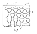
Eine andere mögliche Anordnung der Vertiefung besteht darin, sie in einem wabenförmigen Muster zueinander anzuordnen, so dass jede Vertiefung unmittelbar von sechs anderen Vertiefungen, die in einem gleichmäßigen Dreieck um diese Vertiefung herum angeordnet sind, umgeben ist. In einem solchen Fall können die Kanäle zwischen jeder Vertiefung in jeweils direkt benachbarten Vertiefungen verlaufen, d.h. im Falle eckständiger Vertiefungen mit zwei anderen Vertiefungen, im Falle randständiger mit drei bzw. fünf benachbarten Vertiefungen und im Falle auf der Hauptfläche des kernteils befindlicher Verbindungen mit sechs weiteren, benachbarten Vertiefungen durch Kanäle verbunden sein.Another possible arrangement of the recess is to arrange it in a honeycomb pattern, so that each recess is directly surrounded by six other recesses arranged in a uniform triangle around this recess. In such a case, the channels between each recess may be in respectively directly adjacent recesses, i. in the case of rectangular depressions with two other depressions, in the case of marginal with three or five adjacent wells and in the case on the main surface of the core part befindlicher compounds with six other adjacent wells be connected by channels.
Die Vertiefungen können beispielsweise einen kreisförmigen Grundriss aufweisen und als Hohlzylinder oder linsenförmige oder kugelförmige Vertiefungen ausgeführt sein. Genau so ist es auch möglich, andere Formen von Vertiefungen im Grundriss zu verwenden, beispielsweise sechseckige, fünfekkige oder viereckige. Die Vertiefungen weisen vorzugsweise eine Tiefe von 0,1 bis 1 mm auf, jedoch hängt die konkret anzuwendende Tiefe von der Fläche des Kernteils und der Menge an aufgebrachtem Klebstoff beim Laminieren ab. Die Vertiefungen können einen gegenseitigen Abstand gemessen von Vertiefungsmitte zu Vertiefungsmitte von 10 mm bis 25 mm aufweisen, wobei auch diese Abstände von der konkreten Ausgestaltung von Ausführungsformen gemäß der vorliegenden Erfindung abhängen, z.B. Materialdicke der Blende, Viskosität des Klebers und andere Parameter.The depressions may, for example, have a circular outline and be designed as hollow cylinders or lenticular or spherical depressions. Exactly so it is also possible other forms of depressions in the Floor plan to use, for example, hexagonal, fünfekkige or square. The depressions preferably have a depth of 0.1 to 1 mm, but the actual depth to be used depends on the area of the core part and the amount of adhesive applied during lamination. The depressions can have a mutual distance measured from center of depression to center of depression of 10 mm to 25 mm, whereby these distances also depend on the specific embodiment of embodiments according to the present invention, eg material thickness of the diaphragm, viscosity of the adhesive and other parameters.
Grundsätzlich sind dem Fachmann auf dem Gebiete der Blendenherstellung geeignete Abmessungen und Abstände bekannt oder können von ihm bestimmt werden.Basically, the person skilled in the art of diaphragm production suitable dimensions and distances are known or can be determined by him.
Die Kanäle können eine Breite von 2 bis 5 mm aufweisen, und eine Tiefe von 0,1 bis 1,5 mm, wobei die konkreten Dimensionierungen von empirischen Werten, der Menge des verwendeten Klebemittels sowie der Viskosität oder dem Abtrocknungsverhalten des Klebemittels beeinflusst werden können.The channels may have a width of 2 to 5 mm, and a depth of 0.1 to 1.5 mm, wherein the specific dimensions of empirical values, the amount of adhesive used and the viscosity or the drying behavior of the adhesive can be influenced.
Somit kann eine Dichte an Vertiefung im Bereich zwischen 1600 bis 10 000 Vertiefungen pro m2 vorliegen. Der Fachmann kann aber nach Bedarf von diesen Werten abweichen.Thus, there may be a density of depression in the range of 1600 to 10,000 recesses per m 2. However, the person skilled in the art can deviate from these values as required.
Die Kanäle können vorzugsweise einen rechteckigen, dreiekkigen oder runden Querschnitt aufweisen, der neben den Notwendigkeiten der Verteilung auch von den zur Verfügung stehenden Möglichkeiten oder Vorteilen bei der Herstellung der Werkzeuge für das Kernteil abhängen kann. Wie bereits ausgeführt, können verschiedene Arten von Klebemitteln verwendet werden. Gemäß üblicher Techniken des Laminierens solcher Blendenelemente ist das Klebemittel vorzugsweise ein pastöses Material, das während des Laminierens von Kernteil und Blende zu einer Schicht von im wesentlichen homogener Dicke zwischen Kernteil und Blende umgeformt wird. Nur durch eine homogene Dicke lässt sich das Auftreten unerwünschter Vorwölbungen oder Dellen in der Blende unterbinden.The channels may preferably have a rectangular, dreiekkigen or round cross-section, which may depend in addition to the needs of distribution also on the available possibilities or advantages in the production of tools for the core part. As already stated, Different types of adhesives can be used. In accordance with conventional techniques of laminating such aperture elements, the adhesive is preferably a pasty material which, during lamination of the core portion and aperture, is formed into a layer of substantially homogeneous thickness between the core portion and the aperture. Only a homogeneous thickness can prevent the occurrence of unwanted protrusions or dents in the aperture.
Um eine Befestigung des erfindungsgemäßen Blendenelements am Einsatzort zu ermöglichen, kann das Kernteil weiterhin zumindest einen Halter zur Befestigung des Blendenelements auf einem Untergrund aufweisen. Entsprechende Haltemechanismen sind dem Fachmann auf dem Gebiete der Blendentechnik geläufig und können beispielsweise Einsteckelemente zur Aufnahme in entsprechende Öffnungen des Untergrunds sein. Solche Einsteckelemente können mit Widerhaken oder ähnlichem ausgestattet sein, um ein nachträgliches Verrutschen nach der Montage des Blendenelements auf dem Untergrund zu verhindern.In order to enable an attachment of the diaphragm element according to the invention at the place of use, the core part may further comprise at least one holder for fixing the diaphragm element on a substrate. Corresponding holding mechanisms are familiar to the person skilled in the art of glare technology and can be, for example, plug-in elements for receiving corresponding openings in the substrate. Such male members may be equipped with barbs or the like to prevent subsequent slippage after mounting the panel member on the ground.
Insbesondere wird es bevorzugt, dass das Blendenelement eine Blende für einen Fahrzeuginnenraum ist.In particular, it is preferred that the diaphragm element is an aperture for a vehicle interior.
Dementsprechend, jedoch auch anderen Anwendungen offen, kann die Blende beispielsweise aus Metallblech, einer Kunststoffplatte, Karbonfasern, Holzfurnier oder einem Laminat bestehen. Laminate, beispielsweise aus Holzfurnier und einem weichen Blech, sind entwickelt worden, um das Splitterverhalten von Holzfurnier zu verbessern.Accordingly, but also open to other applications, the panel may for example consist of sheet metal, a plastic plate, carbon fibers, wood veneer or a laminate. Laminates, for example of wood veneer and a soft sheet, have been developed to improve the splintering behavior of wood veneer.
Metalloberflächen, Holzoberflächen oder Kohlefaseroberflächen sind derzeit als Armaturen- und Seitenverkleidungsausgestaltungen bei Kraftfahrzeugen beliebt, so dass diese natürlicherweise bevorzugte Ausführungsformen der Erfindung darstellen werden. Um das Kernteil vollständig oder teilweise vor den Blicken der Nutzer des verblendeten Geräts zu verbergen, kann das Kernteil einen Rand aufweisen und die Blende an zumindest einer Seite des Kernteils über den Rand hinaus geführt und um diesen herum gebogen sein. Auf diese Weise ist der Rand des Kernteils nicht mehr sichtbar, sondern nur noch die Oberfläche der entsprechend gebogenen Blende.Metal surfaces, wood surfaces or carbon fiber surfaces are currently popular as dashboard and side panel designs in automobiles, so that they will naturally constitute preferred embodiments of the invention. In order to completely or partially hide the core part from the eyes of the users of the veneered device, the core part may have an edge and the diaphragm may be led beyond the edge on at least one side of the core part and bent around it. In this way, the edge of the core part is no longer visible, but only the surface of the corresponding curved aperture.
Das Kernteil kann Kunststoff enthalten oder aus Kunststoff bestehen, beispielsweise ein entsprechendes Spritzgussteil sein.The core part may contain plastic or consist of plastic, for example, be a corresponding injection molded part.
Die vorliegende Erfindung stellt ein Blendenelement bereit, welches die Unregelmäßigkeiten der Blendenoberfläche des Standes der Technik vermeidet, ohne dass seine Herstellung komplizierter würde.The present invention provides an aperture member which avoids the prior art aperture surface irregularities without complicating its manufacture.
Im folgenden soll die Erfindung unter Bezugnahme auf die Zeichnungen anhand konkretisierter Ausführungsbeispiele näher erläutert werden, wobei:
- Fig. 1
- eine schematische Darstellung des Laminiervorgangs und der daran beteiligten Elemente ist;
- Fig. 2
- die Oberseite eines Kernteils einer ersten Ausführungsform der vorliegenden Erfindung darstellt;
- Fig. 3
- die Anordnung von Vertiefungen und Kanälen gemäß einer weiteren Ausführungsform der vorliegenden Erfindung zeigt;
- Fig. 4
- eine weitere Anordnung von Vertiefungen und Kanälen gemäß einer weiteren Ausführungsform der vorliegenden Erfindung zeigt; und
- Fig. 5
- noch eine Anordnung von Vertiefungen und Kanälen gemäß einer weiteren Ausführungsform der vorliegenden Erfindung zeigt.
- Fig. 1
- is a schematic representation of the lamination process and the elements involved therewith;
- Fig. 2
- Fig. 11 illustrates the top of a core portion of a first embodiment of the present invention;
- Fig. 3
- shows the arrangement of pits and channels according to another embodiment of the present invention;
- Fig. 4
- shows another arrangement of recesses and channels according to another embodiment of the present invention; and
- Fig. 5
- Still another arrangement of wells and channels according to another embodiment of the present invention shows.
Durch den beim Laminieren ausgeübten Druck des Stößels 3 werden die Klebemittelraupen 30 flach gedrückt und laufen zumindest teilweise in die Vertiefungen, wo überschüssiges Klebemittel aufgenommen wird.As a result of the pressure exerted by the
Die Oberfläche eines Kernteils gemäß einer ersten Ausführungsform der Erfindung ist in
In dem in
In einer nächsten Ausführungsform der vorliegenden Erfindung wird, wie in
Es versteht sich, dass die Erfindung nicht auf die dargestellten Ausführungsformen insbesondere der Kanalanordnungen beschränkt sind. Vielmehr ist eine Vielzahl von Varianten denkbar, welche von der dargestellten Lösung auch bei grundsätzlich anders gearteten Ausführungsformen Gebrauch machen, wobei der Schutzumfang der vorliegenden Erfindung durch die Patentansprüche definiert ist.It is understood that the invention is not limited to the illustrated embodiments, in particular the channel arrangements. Rather, a variety of variants is conceivable, which make use of the illustrated solution even with fundamentally different embodiments, the scope of the present invention being defined by the patent claims.
Claims (20)
- A laminated trim element, comprising:a core part (10);an adhesive (30) applied on the core part (10); anda trim panel (20) arranged on the core part (10) and laminated with the core part (10) by means of the adhesive (30); whereinthe core part (10) comprises an arrangement of a plurality of recesses (11) for receiving and distributing adhesive (30) during laminating the trim panel (20) onto the core part (10), and wherein the recesses (11) are Interconnected by means of channels (16, 17, 18, 19);characterized in that the channels (16, 17, 18, 19) have a width of 2 mm to 5 mm.
- The trim element according to claim 1, characterized in that the channels (16, 17, 18, 19) each Interconnect such a number off recesses (11) that a uniform distribution of the adhesive (30) between the recesses (11) is ensured during laminating the core part (10) with the trim panel (20).
- The trim element according to claim 1 or 2, characterized in that the recesses (11) are arranged on the surface of the core part (10) In rows (14) and columns (15) orthogonal thereto.
- The trim element according to claim 3, characterized in that the channels (16, 17) extend from recess (11) to recess (11) within each row (14) and/or each column (15).
- The trim element according to one of claims 1 to 4, characterized in that the channels (16, 17, 18) extend between each recess and each of the recesses (11) directly adjacent thereto.
- The trim element according to one of the preceding claims, characterized in that the recesses (11) are In a honeycomb arrangement with one another.
- The trim element according to one of the preceding claims, characterized in that the channels (19) extend between each recess (11) and each of the recesses (11) directly adjacent thereto.
- The trim element according to one of claims 1 to 7, characterized in that the recesses (11) comprises a circular plan view.
- The trim element according to one of claims 1 to 8, characterized in that the recesses (11) comprise a depth of 0.1 to 1 mm.
- The trim element according to one of claims 1 to 9, characterized in that the recesses (11) have a mutual spacing of 10 mm to 25 mm as measured between centers of recesses.
- The trim element according to one of claims 1 to 10, characterized in that the recesses (11) comprise a density of 1600 to 10,000 recesses (11) per square meter.
- The trim element according to at least one of the preceding claims, characterized in that the channels (16, 17, 18, 19) comprise a depth of 0.1 to 1 mm.
- The trim element according to at least one of the preceding claims, characterized in that the channels (16, 17, 18, 19) comprise a rectangular, triangular or round cross section.
- The trim element according to at least one of the preceding claims, characterized in that the adhesive (30) is a paste-like material which is formed as a layer of a substantially homogeneous thickness between the core part (10) and the trim panel (20) through laminating the core part (10) with the trim panel (20).
- The trim element according to at least one of the preceding claims, characterized in that the core part (10) further comprises at least one mounting device (12) for attachIng the trim element to a base.
- The trim element according to claim 15, characterized in that the mounting devices are plug-In elements (12, 13) to be received In corresponding openings of a base.
- The trim element according to at least one of the preceding claims, characterized in that it is a trim panel for the interior of a vehicle.
- The trim element according to at least one of the preceding claims, characterized in that the trim panel (20) consists of sheet metal, a plastic plate, carbon fiber, wood veneer or a laminate.
- The trim element according to at least one of the preceding claims, characterized in that the core part (10) comprises an edge and the trim panel (20) extends on at least one side of the core part (10) beyond the edge thereof and Is bent around It.
- The trim element according to at least one of the preceding claims, characterized in that the core part (10) contains plastic.
Applications Claiming Priority (2)
| Application Number | Priority Date | Filing Date | Title |
|---|---|---|---|
| DE10242887 | 2002-09-16 | ||
| DE10242887A DE10242887B4 (en) | 2002-09-16 | 2002-09-16 | Laminated panel element |
Publications (3)
| Publication Number | Publication Date |
|---|---|
| EP1398144A2 EP1398144A2 (en) | 2004-03-17 |
| EP1398144A3 EP1398144A3 (en) | 2004-12-15 |
| EP1398144B1 true EP1398144B1 (en) | 2010-11-10 |
Family
ID=31724792
Family Applications (1)
| Application Number | Title | Priority Date | Filing Date |
|---|---|---|---|
| EP03019639A Expired - Lifetime EP1398144B1 (en) | 2002-09-16 | 2003-09-05 | Laminated trim element |
Country Status (3)
| Country | Link |
|---|---|
| EP (1) | EP1398144B1 (en) |
| AT (1) | ATE487594T1 (en) |
| DE (2) | DE10242887B4 (en) |
Families Citing this family (2)
| Publication number | Priority date | Publication date | Assignee | Title |
|---|---|---|---|---|
| DE102004023058B4 (en) * | 2004-05-11 | 2006-11-02 | Bayerische Motoren Werke Ag | Method for producing a body part for a vehicle and a body part produced according to this method |
| DE102011014513B4 (en) * | 2010-12-29 | 2018-11-15 | Quin Gmbh | Manufacturing process for molded parts with different surface materials |
Family Cites Families (9)
| Publication number | Priority date | Publication date | Assignee | Title |
|---|---|---|---|---|
| DE2944797C2 (en) * | 1979-11-06 | 1983-01-05 | Wechsler & Sellner Kg, 8806 Neuendettelsau | Method for producing a curved strip section |
| JPH0324942A (en) * | 1989-06-23 | 1991-02-01 | Dainippon Printing Co Ltd | Decorative sheet having three-dimensional effect |
| DE8911313U1 (en) * | 1989-09-22 | 1989-11-16 | Dr. Johannes Heidenhain Gmbh, 8225 Traunreut, De | |
| DE4305611A1 (en) * | 1993-02-24 | 1994-08-25 | Daimler Benz Ag | Process for producing a veneered and curved covering part from a wood / metal laminate, in particular an interior fitting part of motor vehicles |
| DE19523900C1 (en) * | 1995-06-30 | 1997-01-16 | Bosch Gmbh Robert | Process for the pretreatment of a plastic surface to be glued |
| DE19706712A1 (en) * | 1996-03-01 | 1997-12-18 | Volkswagen Ag | Folding surface coverings over edges |
| US20010046587A1 (en) * | 1998-12-21 | 2001-11-29 | Raj S. Michael | Encapsulated self adhering acoustic mat for sandwich used in vehicle interior systems |
| FR2796388B1 (en) | 1999-07-16 | 2003-01-03 | Robert Stehle | METHOD AND SYSTEM FOR PREPARING SURFACES BEFORE DEPOSITING AN ADHESIVE OR DECORATIVE PRODUCT |
| DE10105893A1 (en) * | 2001-02-09 | 2002-08-22 | Bosch Gmbh Robert | Laminar component, is produced by forming micro-structured cut-outs in the surface of one of the seam sections using a laser, and then adhering the surfaces together |
-
2002
- 2002-09-16 DE DE10242887A patent/DE10242887B4/en not_active Expired - Fee Related
-
2003
- 2003-09-05 EP EP03019639A patent/EP1398144B1/en not_active Expired - Lifetime
- 2003-09-05 AT AT03019639T patent/ATE487594T1/en active
- 2003-09-05 DE DE50313252T patent/DE50313252D1/en not_active Expired - Lifetime
Also Published As
| Publication number | Publication date |
|---|---|
| EP1398144A3 (en) | 2004-12-15 |
| DE50313252D1 (en) | 2010-12-23 |
| ATE487594T1 (en) | 2010-11-15 |
| DE10242887B4 (en) | 2007-10-18 |
| EP1398144A2 (en) | 2004-03-17 |
| DE10242887A1 (en) | 2004-03-25 |
Similar Documents
| Publication | Publication Date | Title |
|---|---|---|
| DE102014104084A1 (en) | Elastomeric alignment system, method of making same, and cutting punches therefor | |
| DE602005005394T2 (en) | Fastening device for self-piercing rivets with improved die | |
| EP1134438A2 (en) | Connection assembly to mount a fastening element on a structural member | |
| DE112012007279T5 (en) | Vehicle inner panel and method of making same | |
| DE2244945A1 (en) | METHOD FOR MECHANICAL CONNECTING SOCKET-TYPE PARTS TO BOARD-TYPE PARTS | |
| DE102012102637A1 (en) | Method for producing a floor or wall element | |
| DE3016140A1 (en) | METHOD FOR PRODUCING HOLE AND CUTTING MOLDED FROM STEEL TAPE. PUNCHING TOOLS | |
| DE102009051392B4 (en) | Method for producing a composite body from at least one prefabricated metal component and at least one plastic component and positively bonded composite body | |
| WO2019096475A1 (en) | Method for producing a composite component | |
| EP0947778A2 (en) | Insulation element for mounting the pipes of a surface, esp. underfloor heating | |
| EP1398144B1 (en) | Laminated trim element | |
| EP0370353A2 (en) | Method of making a postforming-laminate | |
| WO2017008886A1 (en) | Method for producing a veneer | |
| EP3353430B1 (en) | Furniture connector and piece of furniture produced therewith | |
| DE4441095A1 (en) | Adherent fastening element produced from thermoplastic sheet | |
| EP1398137B1 (en) | Lamination stamp with an elastic element, laminating press and process of fabrication | |
| DE102009009256A1 (en) | Method for producing acoustic active panel that is utilized during e.g. fire protection, involves installing embossing die on section of embossing mold, and moving press-Stamp downwards up to embossing stop unit | |
| DE102016117406B4 (en) | Sink accessory and method of making a sink accessory | |
| DE202020100786U1 (en) | Relief plate | |
| DE8209206U1 (en) | CHAIR SEAT, BACKREST OR SEAT SHELL MADE OF CARDBOARD OR CARDBOARD | |
| EP0555499A1 (en) | Method for producing a furniture front panel made of wood and the furniture front panel so produced | |
| DE3219674A1 (en) | COLD ROLLING TOOL AND METHOD FOR PRODUCING IT | |
| EP3348770B1 (en) | Method for manufacturing a door leaf and door leaf with filling area | |
| DE19821482A1 (en) | Tool for the production of structured thin sheets | |
| EP3845279A1 (en) | Ski or snowboard and method for its manufacture |
Legal Events
| Date | Code | Title | Description |
|---|---|---|---|
| PUAI | Public reference made under article 153(3) epc to a published international application that has entered the european phase |
Free format text: ORIGINAL CODE: 0009012 |
|
| AK | Designated contracting states |
Kind code of ref document: A2 Designated state(s): AT BE BG CH CY CZ DE DK EE ES FI FR GB GR HU IE IT LI LU MC NL PT RO SE SI SK TR |
|
| AX | Request for extension of the european patent |
Extension state: AL LT LV MK |
|
| PUAL | Search report despatched |
Free format text: ORIGINAL CODE: 0009013 |
|
| AK | Designated contracting states |
Kind code of ref document: A3 Designated state(s): AT BE BG CH CY CZ DE DK EE ES FI FR GB GR HU IE IT LI LU MC NL PT RO SE SI SK TR |
|
| AX | Request for extension of the european patent |
Extension state: AL LT LV MK |
|
| 17P | Request for examination filed |
Effective date: 20050610 |
|
| AKX | Designation fees paid |
Designated state(s): AT BE BG CH CY CZ DE DK EE ES FI FR GB GR HU IE IT LI LU MC NL PT RO SE SI SK TR |
|
| GRAP | Despatch of communication of intention to grant a patent |
Free format text: ORIGINAL CODE: EPIDOSNIGR1 |
|
| RIC1 | Information provided on ipc code assigned before grant |
Ipc: B32B 37/12 20060101AFI20100329BHEP |
|
| GRAS | Grant fee paid |
Free format text: ORIGINAL CODE: EPIDOSNIGR3 |
|
| GRAA | (expected) grant |
Free format text: ORIGINAL CODE: 0009210 |
|
| AK | Designated contracting states |
Kind code of ref document: B1 Designated state(s): AT BE BG CH CY CZ DE DK EE ES FI FR GB GR HU IE IT LI LU MC NL PT RO SE SI SK TR |
|
| REG | Reference to a national code |
Ref country code: GB Ref legal event code: FG4D Free format text: NOT ENGLISH |
|
| REG | Reference to a national code |
Ref country code: CH Ref legal event code: EP |
|
| REG | Reference to a national code |
Ref country code: IE Ref legal event code: FG4D Free format text: LANGUAGE OF EP DOCUMENT: GERMAN |
|
| REF | Corresponds to: |
Ref document number: 50313252 Country of ref document: DE Date of ref document: 20101223 Kind code of ref document: P |
|
| REG | Reference to a national code |
Ref country code: NL Ref legal event code: VDEP Effective date: 20101110 |
|
| PG25 | Lapsed in a contracting state [announced via postgrant information from national office to epo] |
Ref country code: FI Free format text: LAPSE BECAUSE OF FAILURE TO SUBMIT A TRANSLATION OF THE DESCRIPTION OR TO PAY THE FEE WITHIN THE PRESCRIBED TIME-LIMIT Effective date: 20101110 Ref country code: CY Free format text: LAPSE BECAUSE OF FAILURE TO SUBMIT A TRANSLATION OF THE DESCRIPTION OR TO PAY THE FEE WITHIN THE PRESCRIBED TIME-LIMIT Effective date: 20101110 Ref country code: NL Free format text: LAPSE BECAUSE OF FAILURE TO SUBMIT A TRANSLATION OF THE DESCRIPTION OR TO PAY THE FEE WITHIN THE PRESCRIBED TIME-LIMIT Effective date: 20101110 Ref country code: SE Free format text: LAPSE BECAUSE OF FAILURE TO SUBMIT A TRANSLATION OF THE DESCRIPTION OR TO PAY THE FEE WITHIN THE PRESCRIBED TIME-LIMIT Effective date: 20101110 Ref country code: PT Free format text: LAPSE BECAUSE OF FAILURE TO SUBMIT A TRANSLATION OF THE DESCRIPTION OR TO PAY THE FEE WITHIN THE PRESCRIBED TIME-LIMIT Effective date: 20110310 Ref country code: BG Free format text: LAPSE BECAUSE OF FAILURE TO SUBMIT A TRANSLATION OF THE DESCRIPTION OR TO PAY THE FEE WITHIN THE PRESCRIBED TIME-LIMIT Effective date: 20110210 Ref country code: SI Free format text: LAPSE BECAUSE OF FAILURE TO SUBMIT A TRANSLATION OF THE DESCRIPTION OR TO PAY THE FEE WITHIN THE PRESCRIBED TIME-LIMIT Effective date: 20101110 |
|
| REG | Reference to a national code |
Ref country code: IE Ref legal event code: FD4D |
|
| PG25 | Lapsed in a contracting state [announced via postgrant information from national office to epo] |
Ref country code: GR Free format text: LAPSE BECAUSE OF FAILURE TO SUBMIT A TRANSLATION OF THE DESCRIPTION OR TO PAY THE FEE WITHIN THE PRESCRIBED TIME-LIMIT Effective date: 20110211 |
|
| PG25 | Lapsed in a contracting state [announced via postgrant information from national office to epo] |
Ref country code: EE Free format text: LAPSE BECAUSE OF FAILURE TO SUBMIT A TRANSLATION OF THE DESCRIPTION OR TO PAY THE FEE WITHIN THE PRESCRIBED TIME-LIMIT Effective date: 20101110 Ref country code: IE Free format text: LAPSE BECAUSE OF FAILURE TO SUBMIT A TRANSLATION OF THE DESCRIPTION OR TO PAY THE FEE WITHIN THE PRESCRIBED TIME-LIMIT Effective date: 20101110 Ref country code: ES Free format text: LAPSE BECAUSE OF FAILURE TO SUBMIT A TRANSLATION OF THE DESCRIPTION OR TO PAY THE FEE WITHIN THE PRESCRIBED TIME-LIMIT Effective date: 20110221 Ref country code: CZ Free format text: LAPSE BECAUSE OF FAILURE TO SUBMIT A TRANSLATION OF THE DESCRIPTION OR TO PAY THE FEE WITHIN THE PRESCRIBED TIME-LIMIT Effective date: 20101110 |
|
| PG25 | Lapsed in a contracting state [announced via postgrant information from national office to epo] |
Ref country code: DK Free format text: LAPSE BECAUSE OF FAILURE TO SUBMIT A TRANSLATION OF THE DESCRIPTION OR TO PAY THE FEE WITHIN THE PRESCRIBED TIME-LIMIT Effective date: 20101110 Ref country code: RO Free format text: LAPSE BECAUSE OF FAILURE TO SUBMIT A TRANSLATION OF THE DESCRIPTION OR TO PAY THE FEE WITHIN THE PRESCRIBED TIME-LIMIT Effective date: 20101110 Ref country code: SK Free format text: LAPSE BECAUSE OF FAILURE TO SUBMIT A TRANSLATION OF THE DESCRIPTION OR TO PAY THE FEE WITHIN THE PRESCRIBED TIME-LIMIT Effective date: 20101110 |
|
| PLBE | No opposition filed within time limit |
Free format text: ORIGINAL CODE: 0009261 |
|
| STAA | Information on the status of an ep patent application or granted ep patent |
Free format text: STATUS: NO OPPOSITION FILED WITHIN TIME LIMIT |
|
| 26N | No opposition filed |
Effective date: 20110811 |
|
| REG | Reference to a national code |
Ref country code: DE Ref legal event code: R097 Ref document number: 50313252 Country of ref document: DE Effective date: 20110811 |
|
| PG25 | Lapsed in a contracting state [announced via postgrant information from national office to epo] |
Ref country code: IT Free format text: LAPSE BECAUSE OF FAILURE TO SUBMIT A TRANSLATION OF THE DESCRIPTION OR TO PAY THE FEE WITHIN THE PRESCRIBED TIME-LIMIT Effective date: 20101110 |
|
| BERE | Be: lapsed |
Owner name: SELLNER G.M.B.H. Effective date: 20110930 |
|
| PG25 | Lapsed in a contracting state [announced via postgrant information from national office to epo] |
Ref country code: MC Free format text: LAPSE BECAUSE OF NON-PAYMENT OF DUE FEES Effective date: 20110930 |
|
| REG | Reference to a national code |
Ref country code: CH Ref legal event code: PL |
|
| GBPC | Gb: european patent ceased through non-payment of renewal fee |
Effective date: 20110905 |
|
| REG | Reference to a national code |
Ref country code: FR Ref legal event code: ST Effective date: 20120531 |
|
| PG25 | Lapsed in a contracting state [announced via postgrant information from national office to epo] |
Ref country code: BE Free format text: LAPSE BECAUSE OF NON-PAYMENT OF DUE FEES Effective date: 20110930 |
|
| PG25 | Lapsed in a contracting state [announced via postgrant information from national office to epo] |
Ref country code: LI Free format text: LAPSE BECAUSE OF NON-PAYMENT OF DUE FEES Effective date: 20110930 Ref country code: CH Free format text: LAPSE BECAUSE OF NON-PAYMENT OF DUE FEES Effective date: 20110930 |
|
| PG25 | Lapsed in a contracting state [announced via postgrant information from national office to epo] |
Ref country code: GB Free format text: LAPSE BECAUSE OF NON-PAYMENT OF DUE FEES Effective date: 20110905 Ref country code: FR Free format text: LAPSE BECAUSE OF NON-PAYMENT OF DUE FEES Effective date: 20110930 |
|
| REG | Reference to a national code |
Ref country code: DE Ref legal event code: R081 Ref document number: 50313252 Country of ref document: DE Owner name: NBHX TRIM GMBH, DE Free format text: FORMER OWNER: SELLNER GMBH, 91564 NEUENDETTELSAU, DE Effective date: 20121024 |
|
| REG | Reference to a national code |
Ref country code: AT Ref legal event code: MM01 Ref document number: 487594 Country of ref document: AT Kind code of ref document: T Effective date: 20110905 |
|
| PG25 | Lapsed in a contracting state [announced via postgrant information from national office to epo] |
Ref country code: AT Free format text: LAPSE BECAUSE OF NON-PAYMENT OF DUE FEES Effective date: 20110905 |
|
| PG25 | Lapsed in a contracting state [announced via postgrant information from national office to epo] |
Ref country code: LU Free format text: LAPSE BECAUSE OF NON-PAYMENT OF DUE FEES Effective date: 20110905 |
|
| PG25 | Lapsed in a contracting state [announced via postgrant information from national office to epo] |
Ref country code: TR Free format text: LAPSE BECAUSE OF FAILURE TO SUBMIT A TRANSLATION OF THE DESCRIPTION OR TO PAY THE FEE WITHIN THE PRESCRIBED TIME-LIMIT Effective date: 20101110 |
|
| PG25 | Lapsed in a contracting state [announced via postgrant information from national office to epo] |
Ref country code: HU Free format text: LAPSE BECAUSE OF FAILURE TO SUBMIT A TRANSLATION OF THE DESCRIPTION OR TO PAY THE FEE WITHIN THE PRESCRIBED TIME-LIMIT Effective date: 20101110 |
|
| PGFP | Annual fee paid to national office [announced via postgrant information from national office to epo] |
Ref country code: DE Payment date: 20191128 Year of fee payment: 17 |
|
| REG | Reference to a national code |
Ref country code: DE Ref legal event code: R119 Ref document number: 50313252 Country of ref document: DE |
|
| PG25 | Lapsed in a contracting state [announced via postgrant information from national office to epo] |
Ref country code: DE Free format text: LAPSE BECAUSE OF NON-PAYMENT OF DUE FEES Effective date: 20210401 |