EP1398094A1 - Method and device for determining the arm length of bent products - Google Patents
Method and device for determining the arm length of bent products Download PDFInfo
- Publication number
- EP1398094A1 EP1398094A1 EP02020284A EP02020284A EP1398094A1 EP 1398094 A1 EP1398094 A1 EP 1398094A1 EP 02020284 A EP02020284 A EP 02020284A EP 02020284 A EP02020284 A EP 02020284A EP 1398094 A1 EP1398094 A1 EP 1398094A1
- Authority
- EP
- European Patent Office
- Prior art keywords
- bending
- bending angle
- leg
- determining
- leg end
- Prior art date
- Legal status (The legal status is an assumption and is not a legal conclusion. Google has not performed a legal analysis and makes no representation as to the accuracy of the status listed.)
- Granted
Links
Images


Classifications
-
- B—PERFORMING OPERATIONS; TRANSPORTING
- B21—MECHANICAL METAL-WORKING WITHOUT ESSENTIALLY REMOVING MATERIAL; PUNCHING METAL
- B21D—WORKING OR PROCESSING OF SHEET METAL OR METAL TUBES, RODS OR PROFILES WITHOUT ESSENTIALLY REMOVING MATERIAL; PUNCHING METAL
- B21D5/00—Bending sheet metal along straight lines, e.g. to form simple curves
- B21D5/002—Positioning devices
-
- B—PERFORMING OPERATIONS; TRANSPORTING
- B21—MECHANICAL METAL-WORKING WITHOUT ESSENTIALLY REMOVING MATERIAL; PUNCHING METAL
- B21D—WORKING OR PROCESSING OF SHEET METAL OR METAL TUBES, RODS OR PROFILES WITHOUT ESSENTIALLY REMOVING MATERIAL; PUNCHING METAL
- B21D5/00—Bending sheet metal along straight lines, e.g. to form simple curves
- B21D5/02—Bending sheet metal along straight lines, e.g. to form simple curves on press brakes without making use of clamping means
- B21D5/0209—Tools therefor
-
- G—PHYSICS
- G01—MEASURING; TESTING
- G01B—MEASURING LENGTH, THICKNESS OR SIMILAR LINEAR DIMENSIONS; MEASURING ANGLES; MEASURING AREAS; MEASURING IRREGULARITIES OF SURFACES OR CONTOURS
- G01B21/00—Measuring arrangements or details thereof, where the measuring technique is not covered by the other groups of this subclass, unspecified or not relevant
- G01B21/02—Measuring arrangements or details thereof, where the measuring technique is not covered by the other groups of this subclass, unspecified or not relevant for measuring length, width, or thickness
-
- G—PHYSICS
- G01—MEASURING; TESTING
- G01B—MEASURING LENGTH, THICKNESS OR SIMILAR LINEAR DIMENSIONS; MEASURING ANGLES; MEASURING AREAS; MEASURING IRREGULARITIES OF SURFACES OR CONTOURS
- G01B21/00—Measuring arrangements or details thereof, where the measuring technique is not covered by the other groups of this subclass, unspecified or not relevant
- G01B21/22—Measuring arrangements or details thereof, where the measuring technique is not covered by the other groups of this subclass, unspecified or not relevant for measuring angles or tapers; for testing the alignment of axes
Landscapes
- Physics & Mathematics (AREA)
- General Physics & Mathematics (AREA)
- Engineering & Computer Science (AREA)
- Mechanical Engineering (AREA)
- Bending Of Plates, Rods, And Pipes (AREA)
- Cable Accessories (AREA)
- Length-Measuring Instruments Using Mechanical Means (AREA)
Abstract
Description
Die Erfindung betrifft ein Verfahren und eine Vorrichtung zur Bestimmung der Schenkellänge wenigstens eines von zwei mittels eines Biegewerkzeugs unter einem Biegewinkel gegeneinander gebogener Schenkel an einem Biegeteil, wobei ein Biegewinkelscheitel im Schnittpunkt geradliniger und den Biegewinkel einschließender Verlaufsrichtungen der Schenkel des Biegeteils liegt und ein Schenkelende des betreffenden Schenkels diesen an der von dem Biegewinkelscheitel abliegenden Seite begrenzt. Die Erfindung betrifft des Weiteren ein Verfahren und eine Vorrichtung zum Biegen von Werkstücken, im Falle derer von dem vorstehenden Verfahren bzw. von der vorstehenden Vorrichtung zur Bestimmung der Schenkellänge an einem Biegeteil Gebrauch gemacht wird.The invention relates to a method and a device for Determination of the leg length of at least one of two means a bending tool bent at a bending angle against each other Leg on a bent part, wherein a bending angle vertex at the intersection of rectilinear and the bending angle enclosing Course of the legs of the bent part lies and a leg end of the leg in question this bounded by the bending angle vertex side. The The invention further relates to a method and a device for bending workpieces, in the case of those of the above Method and of the above device for determination the leg length made use of a bent part becomes.
Neben dem Biegewinkel bildet die Schenkellänge das wichtigste Funktionsmaß eines Biegeteils. Derzeit üblich ist es, die Schenkellänge an einem mittels einer Biegemaschine erstellten Biegeteil nach dessen Entnahme aus der Biegemaschine manuell zu bestimmen. Die Genauigkeit der Schenkellängenbestimmung wird dabei insbesondere durch den Umstand beeinträchtigt, dass die zu vermessenden Schenkel des Biegeteils an der Biegelinie nicht ideal geradlinig aneinanderstoßen sondern vielmehr mit einem Radius ineinander übergehen. Der Biegewinkelscheitel als einer der Endpunkte eines Biegeteilschenkels und als Schnittpunkt der geradlinigen Verläufe beider Biegeteilschenkel ist daher nicht real existent. Folglich kann der Biegewinkelscheitel bei der Bestimmung einer Schenkellänge an einem Biegeteil beispielsweise nicht unmittelbar angetastet werden. Besondere und nur unter Einsatz aufwändiger Messtechnik zu bewältigende Schwierigkeiten treten im Falle von offenen Biegewinkeln, d.h. von Biegewinkeln über 90°, auf. In addition to the bending angle, the leg length forms the most important Functional dimension of a bent part. Currently it is the usual Leg length at one created by means of a bending machine Bending part manually after its removal from the bending machine determine. The accuracy of the leg length determination is This is particularly affected by the fact that the not to be measured leg of the bent part at the bend line ideally in a straight line but rather with one another Radius merge into each other. The bending angle vertex as one the end points of a bent part leg and as an intersection of rectilinear courses of both bending part legs is therefore not real existent. Consequently, the bending angle peak in the Determining a leg length of a bent part, for example not directly touched. Special and only under Use of elaborate measurement technology to overcome difficulties occur in the case of open bending angles, i. of bending angles over 90 °, up.
Eine automatisierte und möglichst genaue Ermittlung von Schenkellängen an Biegeteilen insbesondere im Interesse einer Optimierung der biegenden Werkstückbearbeitung zu ermöglichen, hat sich die vorliegende Erfindung zum Ziel gesetzt.An automated and accurate determination of leg lengths on bent parts, in particular in the interests of optimization to allow the bending workpiece machining has the present invention set the goal.
Erfindungsgemäß gelöst wird diese Aufgabe durch die Verfahren
gemäß den Patentansprüchen 1 und 6 sowie durch die Vorrichtungen
gemäß den Patentansprüchen 8 und 18.This object is achieved according to the invention by the methods
according to claims 1 and 6 and by the devices
according to
Demnach verbleibt das zu vermessende Biegeteil im Falle der Erfindung in dem Biegewerkzeug, wo es definiert angeordnet ist. Die betreffende Schenkellänge wird im Interesse einer möglichst genauen Bestimmung nicht unmittelbar sondern über die Lage des Biegewinkelscheitels und die Lage des Schenkelendes ermittelt. Als Lage des Biegewinkelscheitels wird dabei die Lage des in der Praxis üblicherweise nicht real existierenden Schnittpunktes der geradlinigen Verläufe der aneinanderstoßenden Biegeteilschenkel berücksichtigt.Accordingly, remains to be measured bending part in the case of the invention in the bending tool where it is defined. The leg length is in the interest of a possible exact determination not immediately but about the location of the Bending angle peak and the position of the leg end determined. As the position of the bending angle vertex, the position of the in the practice of usually not really existing intersection the rectilinear courses of the abutting bending part legs considered.
Besondere Ausführungsarten des Verfahrens nach Patentanspruch 1
sind in den abhängigen Patentansprüchen 2 bis 5, eine besondere
Ausführungsart des Verfahrens nach Patentanspruch 6 ist in dem
abhängigen Patentanspruch 7 beschrieben. Besondere Ausführungsarten
der Vorrichtung nach Patentanspruch 8 ergeben sich aus
den abhängigen Patentansprüchen 9 bis 17, besondere Ausführungsarten
der Vorrichtung nach Patentanspruch 18 aus den abhängigen
Patentansprüchen 19 bis 24.Special embodiments of the method according to claim 1
are in the
Gemäß Patentanspruch 2 wird das zu vermessende Biegeteil zur
definierten Anordnung in dem Biegewerkzeug gehalten. Vorrichtungsbezogen
umgesetzt wird dieses Verfahrensmerkmal durch die
Haltevorrichtung gemäß Patentanspruch 9. In bevorzugter Ausgestaltung
der erfindungsgemäßen Biegevorrichtung dient als Haltevorrichtung
zur definierten Anordnung des Biegeteils in dem
Biegewerkzeug das Biegewerkzeug selbst (Patentanspruch 19).According to
Die Bestimmung der Lage des Biegewinkelscheitels erfolgt in
vorteilhafter Ausgestaltung der Erfindung unter Ermittlung des
Biegewinkels (Patentansprüche 3, 10). Zur Ermittlung des Biegewinkels
bestehen dabei verschiedene Möglichkeiten. Beispielsweise
kann der Biegewinkel gemessen werden. Alternativ kann der
Biegewinkel aber auch nach einer sogenannten, in einer Vorrichtungssteuerung
zu hinterlegenden "Biegeformel" berechnet werden.
Die Biegeformel beschreibt den Biegewinkel als Funktion
von werkstück- und werkzeugbezogenen Parametern.The determination of the position of the bending angle vertex takes place in
Advantageous embodiment of the invention with determination of the
Bending angle (
Im Falle der in Patentanspruch 4 beschriebenen Variante des erfindungsgemäßen
Verfahrens zur Schenkellängenbestimmung wird
das zu vermessende Biegeteil an einer Anlage abgestützt und die
Lage des Biegewinkelscheitels anhand der Lage der Abstützung
des Biegeteils an der Anlage bestimmt. Ebenso wie der Biegewinkel
stellt auch die Lage der Abstützung des Biegeteils an der
betreffenden Anlage eine mit der erforderlichen Genauigkeit und
mit herkömmlichen Mitteln bereitzustellende Grundlage für die
Bestimmung der Lage des Biegewinkelscheitels dar. Entsprechend
sind an der erfindungsgemäßen Vorrichtung gemäß Patentanspruch
11 eine mit der Auswerteeinrichtung in Verbindung stehende
Rechnereinheit sowie eine Anlage für das Biegeteil vorgesehen,
an welcher das Biegeteil bei der Bestimmung der Lage des Biegewinkelscheitels
abgestützt ist. Die Rechnereinheit dient dazu,
anhand der Lage der Abstützung des Biegeteils an der Anlage die
Lage des Biegewinkelscheitels zu ermitteln. In bevorzugter Ausgestaltung
der erfindungsgemäßen Biegevorrichtung dient gemäß
Patentanspruch 20 das Biegewerkzeug als Anlage zur Abstützung
des Biegeteils bei der Bestimmung der Lage des Biegewinkelscheitels.In the case of the variant described in
Gemäß den Patentansprüchen 5, 12 und 17 werden im Falle der Erfindung
der Biegewinkel und/oder die Lage des Schenkelendes
vorzugsweise berührungslos, insbesondere optisch bestimmt. Zu
diesem Zweck denkbar ist beispielsweise die Anwendung des
Lichtschnittverfahrens bzw. der Einsatz von Vorrichtungen zur
Durchführung des Lichtschnittverfahrens. Alternativ oder ergänzend
können aber auch taktile Verfahren bzw. Systeme zum Einsatz
kommen. So ist etwa im Falle der in Patentanspruch 14 beschriebenen
Ausführungsform der erfindungsgemäßen Vorrichtung
zur Schenkellängenbestimmung als Erfassungseinheit zur Erfassung
der Lage des Schenkelendes eine Tasteinrichtung vorgesehen,
die an das Schenkelende anlegbar ist. Gemäß Patentanspruch
15 kann diese Tasteinrichtung mit dem Schenkelende bei dessen
Bewegung während des Biegevorgangs bewegbar sein. Insbesondere
kann als Tasteinrichtung ein Positionieranschlag für das zu
biegende Werkstück genutzt werden (Patentanspruch 16). Entsprechend
ist an der erfindungsgemäßen Biegevorrichtung gemäß Patentanspruch
21 als Tasteinrichtung der Erfassungseinheit zur
Erfassung der Lage des Schenkelendes ein Positionieranschlag
der Biegevorrichtung vorgesehen, an welchem das Werkstück vor
der Bearbeitung zur Positionierung gegenüber dem Biegewerkzeug
anlegbar ist. Im Falle der Erfindungsbauart nach Patentanspruch
22 wird ein derartiger Positionieranschlag zur wenigstens teilweisen
Lagerung einer berührungslosen, insbesondere optischen
Erfassungseinheit zur Erfassung der Lage des Schenkelendes verwendet.
Ausweislich Patentanspruch 23 ist der Positionieranschlag
in Weiterbildung der erfindungsgemäßen Biegevorrichtung
gesteuert bewegbar.According to the
Gemäß den Patentansprüchen 7 und 24 wird sowohl im Rahmen des
erfindungsgemäßen Biegeverfahrens als auch an der erfindungsgemäßen
Biegevorrichtung ein als Ergebnis der Bestimmung der
Schenkellänge eines Schenkels erhaltener Schenkellängen-Istwert
mit einem Schenkellängen-Sollwert verglichen und anhand des Ergebnisses
dieses Ist-/Sollwert-Vergleichs wenigstens ein für
die Schenkellänge maßgebender Parameter zumindest eines nachfolgenden
Biegevorgangs definiert. Als zu definierender Parameter
in Frage kommt beispielsweise der Abstand, mit welchem Positionieranschläge
für das zu biegende Werkstück gegenüber der
von dem Biegewerkzeug definierten Biegelinie einzustellen sind.
Als nachfolgende Biegevorgänge sind sowohl Biegevorgänge an anderen
Werkstücken als auch Biegevorgänge an dem selben Werkstück
denkbar, an welchem zuvor die Schenkellänge als Grundlage
für die nachfolgende Parameterdefinition bestimmt worden ist.
Erfindungsgemäß besteht insbesondere die Möglichkeit, an Biegeteilen
mit mehrfachen Abkantungen die Parameter der einzelnen
Biegevorgänge auf der Grundlage des jeweils vorausgehenden
Schenkellängen-Ist-/Sollwert-Vergleichs derart aufeinander abgestimmt
zu definieren, dass die für das Biegeteil vorgegebene
Fertigungstoleranz von den einzelnen Schenkellängen in Summe
eingehalten wird.According to the
Nachstehend wird die Erfindung anhand schematischer Darstellungen zu einem Ausführungsbeispiel näher erläutert. Es zeigen:
- Figur 1
- eine CNC-gesteuerte Biegemaschine mit Gesenkbiegewerkzeug und Hinteranschlagsystem in der stark schematisierten Seitenansicht,
Figur 2- das Hinteranschlagsystem der Biegemaschine gemäß Figur 1 in Einzeldarstellung,
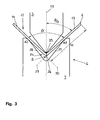
Figur 3- die Verhältnisse an dem Gesenkbiegewerkzeug der Biegemaschine gemäß Figur 1 in Einzeldarstellung und
Figur 4- eine stark schematisierte Darstellung eines Teiles der CNC-Steuerung der Biegemaschine gemäß Figur 1.
- FIG. 1
- a CNC-controlled bending machine with die-bending tool and backgauge system in the highly schematic side view,
- FIG. 2
- the backgauge system of the bending machine according to FIG. 1 in individual representation,
- FIG. 3
- the conditions on the Gesenkbiegewerkzeug the bending machine according to Figure 1 in a detail view and
- FIG. 4
- a highly schematic representation of a part of the CNC control of the bending machine according to Figure 1.
Gemäß Figur 1 besitzt eine Biegemaschine 1 für die Blechbearbeitung
ein Maschinengestell 2, an dem ein Pressbalken 3 hebund
senkbar geführt ist. Zum Antrieb des Pressbalkens 3 dient
ein hydraulischer Pressbalkenantrieb 4.According to Figure 1 has a bending machine 1 for sheet metal processing
a
An dem Pressbalken 3 gehaltert ist ein Oberwerkzeug 5 eines
Biegewerkzeuges in Form eines Gesenkbiegewerkzeuges 6. Dem
Oberwerkzeug 5 zugeordnet ist ein Unterwerkzeug 7, das auf einem
Maschinentisch 8 gelagert ist.Mounted on the
Eine andeutungsweise erkennbare taktile Biegewinkelsensorik 9
ist in das Oberwerkzeug 5 des Gesenkbiegewerkzeuges 6 integriert.
Die Biegewinkelsensorik 9 entspricht in Aufbau und
Funktionsweise der in EP 0 775 028 B1 beschriebenen Vorrichtung. A suggestively detectable tactile
Auf der von der Bedienerseite der Biegemaschine 1 abgewandten
Seite des Gesenkbiegewerkzeuges 6 ist ein Hinteranschlagsystem
10 untergebracht. Gegenüberliegend ist eine Maschinensteuerung
in Form einer CNC-Steuerung 11 vorgesehen.On the side facing away from the operator side of the bending machine 1
Side of the die-bending tool 6 is a
In dem dargestellten Betriebszustand ist ein Abkantvorgang abgeschlossen.
Bei diesem Abkantvorgang erstellt wurde ein Biegeteil
12 mit Schenkeln 13, 14. Ausweislich Figur 1 wird das Biegeteil
12 zwischen dem Oberwerkzeug 5 und dem Unterwerkzeug 7
mit definierter Ausrichtung gehalten.In the illustrated operating state, a bending operation is completed.
In this bending process was created a
Wie im Einzelnen Figur 2 entnommen werden kann, umfasst das
Hinteranschlagsystem 10 zwei Hinteranschläge 15, 16. Dabei
weist der Hinteranschlag 15 einen Anschlagfinger 17, der Hinteranschlag
16 einen Anschlagfinger 18 auf. Die Anschlagfinger
17, 18 bilden Positionieranschläge für den abzukantenden ebenen
Blechzuschnitt und sind unabhängig voneinander jeweils in den
drei Richtungen des Raumes verfahrbar. Die Bewegungssteuerung
der Anschlagfinger 17, 18 erfolgt mittels der CNC-Steuerung 11.
Unterhalb einer Werkstückanlage 19 ist an dem Anschlagfinger 17
eine Kamera 20 angebracht. Entsprechend ist der Anschlagfinger
18 unterhalb einer Werkstückanlage 21 mit einer Kamera 22 versehen.
Die Richtungen der von den Anschlagfingern 17, 18 ausführbaren
Bewegungen sind in Figur 2 durch Pfeile veranschaulicht. As can be seen in detail in FIG. 2, this includes
Gemäß Figur 3 herrschen an dem Gesenkbiegewerkzeug 6 symmetrische
Verhältnisse bezüglich einer Winkelhalbierenden 23 einer
Gesenknut 24 des Unterwerkzeuges 7. Die Winkelhalbierende 23
der Gesenknut 24 fällt zusammen mit der Winkelhalbierenden eines
Biegewinkels ß, der von den Schenkeln 13, 14 des Biegeteils
12 eingeschlossen wird. Zwischen der Winkelhalbierenden 23 und
den Schenkeln 13, 14 des Biegeteils 12 liegt dementsprechend
jeweils ein Winkel der Größe ß/2. An seiner Oberseite wird das
Biegeteil 12 von dem Oberwerkzeug 5 mit einer Oberwerkzeugspitze
25 an einer Biegelinie 26 beaufschlagt. Mit seiner Unterseite
ist das Biegeteil 12 an Flanken 27, 28 der Gesenknut 24 abgestützt,
die somit eine Anlage für das Biegeteil 12 bilden.
Die Punkte bzw. Linien der Abstützung des Biegeteils 12 an den
Flanken 27, 28 der Gesenknut 24 sind in Figur 3 mit A1 und A2
bezeichnet.According to FIG. 3, symmetrical are prevailing on the die bending tool 6
Conditions with respect to an angle bisector 23 a
Wie in Figur 3 deutlich zu erkennen ist, stoßen die Schenkel
13, 14 des Biegeteils 12 nicht mit ideal geradlinigem Verlauf
aneinander sondern gehen vielmehr mit einem Radius ineinander
über. Eine geradlinige Verlaufsrichtung 29 des Schenkels 13 und
eine geradlinige Verlaufsrichtung 30 des Schenkels 14 schneiden
sich in einem Biegewinkelscheitel S, der in Richtung der Winkelhalbierenden
23 unterhalb des Biegeteils 12 liegt. Eine
Schenkellänge b des Schenkels 13 erstreckt sich zwischen dem
Biegewinkelscheitel S und einem Schenkelende E. As can be clearly seen in FIG. 3, the
Aus Gründen der Übersichtlichkeit ist in Figur 3 die in das
Oberwerkzeug 5 des Gesenkbiegewerkzeuges 6 integrierte taktile
Biegewinkelsensorik 9 nicht dargestellt. In bekannter Weise umfasst
die Biegewinkelsensorik 9 zwei Tastscheiben mit unterschiedlichem
Durchmesser, die in ihrer Funktionsstellung symmetrisch
bezüglich der Winkelhalbierenden 23 angeordnet sind und
jeweils an beiden Schenkeln 13, 14 des Biegeteils 12 anliegen.
Ein weiterer wesentlicher Bestandteil der Biegewinkelsensorik 9
ist ein Auswerterechner, der anhand der Differenz der Radien
der beiden Tastscheiben sowie anhand des Abstandes der Tastscheibenmittelpunkte
in Richtung der Winkelhalbierenden 23 den
Biegewinkel ß bestimmt. Bei der Biegewinkelsensorik 9 handelt
es sich somit um eine Vorrichtung zur Ermittlung des Biegewinkels
ß.For reasons of clarity, in
Gemäß Figur 4 ist die Biegewinkelsensorik 9 Teil einer Vorrichtung
31 zur Bestimmung der Lage des Biegewinkelscheitels S.
Verbunden ist die Biegewinkelsensorik 9 dabei mit einer Rechnereinheit
32 die ihrerseits Zugriff hat auf einen Speicher 33,
in welchem der Verlauf der Winkelhalbierenden 23 der Gesenknut
24 an dem Unterwerkzeug 7 sowie die Lage der Abstützpunkte A1,
A2 an den Flanken 27, 28 der Gesenknut 24 in Abhängigkeit von
dem Biegewinkel ß hinterlegt sind. Insofern bilden auch die
Flanken 27, 28 der Gesenknut 24 einen Teil der Vorrichtung 31
zur Bestimmung der Lage des Biegewinkelscheitels S. According to Figure 4, the bending
Anhand des mittels der Biegewinkelsensorik 9 ermittelten Biegewinkels
ß bestimmt die Rechnereinheit 32 den Winkel ß/2, unter
welchem sich die geradlinige Verlaufsrichtung 29 des Schenkels
13 des Biegeteils 12 gegenüber der Winkelhalbierenden 23 der
Gesenknut 24 erstreckt. Aus dem Winkel ß/2, der Lage von A1 sowie
dem Verlauf der Winkelhalbierenden 23 ermittelt die Rechnereinheit
32 schließlich die Lage des Biegewinkelscheitels S
als Schnittpunkt einer die Flanke 27 der Gesenknut 24 in A1
tangierenden und unter dem Winkel ß/2 gegenüber der Winkelhalbierenden
23 verlaufenden Geraden mit der Winkelhalbierenden
23.Based on the determined by means of the
Eine in Figur 4 ebenfalls dargestellte Vorrichtung 34 zu Bestimmung
der Lage des Schenkelendes E umfasst den Hinteranschlag
15 des Hinteranschlagsystems 10 sowie die an dem Anschlagfinger
17 des Hinteranschlages 15 angebrachte Kamera 20.
Diese bildet eine Erfassungseinheit zur Erfassung der Lage des
Schenkelendes E. Das von der Kamera 20 aufgenommene Bild des
Schenkelendes E wird in Form von Signalen einer Rechnereinheit
35 übermittelt. Ebenfalls mit der Rechnereinheit 35 verbunden
ist der Hinteranschlag 15, im Einzelnen dessen Bewegungssteuerung.
Nachdem die Kamera 20 an dem Anschlagfinger 17 eine definierte
Position einnimmt, ist über die Lage des Anschlagfingers
17 die Lage der Kamera 20 bestimmt. Aus der so gewonnenen Lageinformation
sowie den von der Kamera 20 stammenden Signalen
bestimmt die Rechnereinheit 35 die Lage des Schenkelendes E. A likewise shown in Figure 4
Die Nutzung des Anschlagfingers 17 zur Halterung der Kamera 20
empfiehlt sich insbesondere aufgrund des Umstandes, dass der
Anschlagfinger 17 zu dem Zeitpunkt, zu welchem die Lage des
Schenkelendes E zu bestimmen ist, außer Funktion und somit frei
verfügbar ist. Genutzt wird der Anschlagfinger 17, im Einzelnen
dessen Werkstückanlage 19, lediglich zu Beginn des Biegevorgangs.
Zu diesem Zeitpunkt wird der ebene Blechzuschnitt, aus
welchem ein Biegeteil zu erstellen ist, zur Positionierung
gegenüber dem Gesenkbiegewerkzeug 6 an der Werkstückanlage 19,
unter Umständen auch an der Werkstückanlage 21 des Anschlagfingers
18 angelegt. Mittels der als Positionieranschläge dienenden
Anschlagfinger 17, 18 wird der spätere Verlauf der Biegelinie
an dem Biegeteil definiert. Während des Abkantvorgangs und
danach ist der anfänglich ebene Blechzuschnitt von den Anschlagfingern
17, 18 abgehoben. Etwa der bei einem derartigen
Abkantvorgang unter anderem erstellte Schenkel 14 des Biegeteils
12 liegt mit Abstand oberhalb der Anschlagfinger 17, 18.
Letztere sind folglich nach Beginn des Abkantvorganges frei
verfahrbar. Aufgrund ihrer dreiachsigen Beweglichkeit können
die Anschlagfinger 17, 18 jede beliebige Position im Raum einnehmen
und somit die Kamera 20 in jede gewünschte Position
überführen. Insbesondere ist es möglich, die Kamera 20 derart
auszurichten, dass ihre Blickrichtung etwa zur Vermeidung von
Parallaxenfehlern senkrecht zu dem Schenkelende E verläuft. Ergänzend
oder alternativ zu der Kamera 20 kann auch die Kamera
22 an dem Hinteranschlag 16 als Erfassungseinheit zur optischen
Erfassung der Lage des Schenkelendes E dienen. Die Rechnereinheit
35 hat dann (auch) auf die Bewegungssteuerung des Hinteranschlages
16 Zugriff.The use of the
Aus der mittels der Vorrichtung 31 bestimmten Lage des Biegewinkelscheitels
S sowie aus der mittels der Vorrichtung 34 ermittelten
Lage des Schenkelendes E wird in einer Auswerteeinrichtung
36 durch vektorielle Distanzbestimmung die Schenkellänge
b als Strecke zwischen dem Biegewinkelscheitel S und dem
Schenkelende E berechnet. Der so bestimmte Schenkellängen-Istwert
wird in einer Vergleichseinheit 37 mit einem dort hinterlegten
Schenkellängen-Sollwert verglichen. Weicht der Schenkellängen-Ist-
von dem Schenkellängen-Sollwert ab, so wird diese
Abweichung durch eine Korrektureinheit 38 verarbeitet. In dem
gezeigten Beispielsfall wird mittels der Korrektureinheit 38
ein Stellantrieb 39 des Hinteranschlagsystems 10 angesteuert.From the determined by means of the
Sollen etwa nacheinander Abkantungen an verschiedenen Blechen
aber mit gleichem Schenkellängen-Sollwert erstellt werden und
ist die bestimmte Schenkellänge b kleiner als dieser Schenkellängen-Sollwert,
so wird durch entsprechende Ansteuerung des
Stellantriebes 39 das Hinteranschlagsystem 10 um einen in der
Korrektureinheit 38 ermittelten Betrag gegenüber dem Gesenkbiegewerkzeug
6 zurückverfahren. Sind an ein und demselben Blech
mehrere Abkantungen zu erstellen, so kann beispielsweise eine
an der ersten Abkantung festgestellte Abweichung des Schenkellängen-Istwertes
von dem Schenkellängen-Sollwert bei der Einstellung
des Hinteranschlagsystems 10 für den zweiten Biegevorgang
berücksichtigt werden. Auf diese Art und Weise kann automatisiert
dafür gesorgt werden, dass die erstellten Abkantungen
in Summe die vorgegebene Toleranz einhalten.Should about successively bends on different sheets
but be created with the same leg length setpoint and
if the specific leg length b is smaller than this leg length setpoint,
so is by appropriate control of the
Im Übrigen können an der Biegemaschine 1 die Lage des Biegewinkelschenkels S und die Lage des Schenkelendes E auch abweichend von dem vorstehend Beschriebenen bestimmt werden.Incidentally, at the bending machine 1, the position of the bending angle leg S and the position of the leg end E also deviating be determined from that described above.
So lässt sich etwa der Biegewinkel ß auch mittels der in der
CNC-Steuerung 11 hinterlegten Biegeformel berechnen. Diese Biegeformel
beschreibt den Biegewinkel ß als Funktion der Geometrie
von Oberwerkzeug 6 und Unterwerkzeug 7, der Materialfestigkeit,
der Dicke des zu verformenden Bleches und der Eindringtiefe
des Oberwerkzeugs 5 an dem Unterwerkzeug 7. Außerdem
können zur Ermittlung des Biegewinkels ß anstelle der taktilen
Biegewinkelsensorik 9 auch berührungslose optische Systeme eingesetzt
werden. Denkbar ist es, zu diesem Zweck zumindest eine
der Kameras 20, 22 an dem Hinteranschlagsystem 10 einzusetzen.
Entsprechend lässt sich die Lage des Schenkelendes E mit taktilen
Einrichtungen bestimmen. Beispielsweise kann wenigstens einer
der Anschlagfinger 17, 18 an dem Schenkelende E anliegend
diesem während des Abkantvorganges folgen. Durch die Lage des
oder der Anschlagfinger 17, 18 ist die von dem Schenkelende E
eingenommene Position definiert. Schließlich besteht eine Möglichkeit
zur Bestimmung der Lage des Biegewinkelscheitels S
und/oder zur Bestimmung der Lage des Schenkelendes E in der Anwendung
des sogenannten Lichtschnittverfahrens. Beschrieben ist
das Lichtschnittverfahren sowie dessen technische Umsetzung
beispielsweise in DE 43 12 565 A1. Wenigstens eine der Kameras
20, 22 des Hinteranschlagsystems 10 kann dabei unter dem sogenannten
Triangulationswinkel angeordnet werden und eine an dem
Biegeteil 12 erzeugte Lichtspur detektieren.Thus, for example, the bending angle ß also by means of in the
Außer zur Korrektur nachfolgender Bearbeitungsvorgänge kann die
Bestimmung der Schenkellänge b auch dazu dienen, das erstellte
Biegeteil 12 auf Abweichungen von seiner dreidimensionalen
Soll-Gestalt zu überprüfen. So kann etwa bei größeren Abkantlängen
die Schenkellänge b an mehreren Stellen entlang der Biegelinie
26 ermittelt werden. Auch denkbar ist eine Überprüfung
der Winkeligkeit des Biegeteils 12. Die ermittelten Messdaten
lassen sich in jedem Fall automatisiert protokollieren. Die
Auswirkungen der von der Korrektureinheit 38 vorgegebenen Korrekturen
können bei Bedarf visualisiert werden.Except for the correction of subsequent processing operations, the
Determining the leg length b also serve to create the
Claims (24)
Priority Applications (4)
| Application Number | Priority Date | Filing Date | Title |
|---|---|---|---|
| EP02020284A EP1398094B1 (en) | 2002-09-11 | 2002-09-11 | Method and device for determining the arm length of bent products |
| DE50206821T DE50206821D1 (en) | 2002-09-11 | 2002-09-11 | Method and device for determining the leg length on a bent part |
| AT02020284T ATE326297T1 (en) | 2002-09-11 | 2002-09-11 | METHOD AND DEVICE FOR DETERMINING THE LENGTH OF A BENDING PART |
| US10/660,042 US6922903B2 (en) | 2002-09-11 | 2003-09-11 | Method and apparatus for measuring bent workpieces |
Applications Claiming Priority (1)
| Application Number | Priority Date | Filing Date | Title |
|---|---|---|---|
| EP02020284A EP1398094B1 (en) | 2002-09-11 | 2002-09-11 | Method and device for determining the arm length of bent products |
Publications (2)
| Publication Number | Publication Date |
|---|---|
| EP1398094A1 true EP1398094A1 (en) | 2004-03-17 |
| EP1398094B1 EP1398094B1 (en) | 2006-05-17 |
Family
ID=31725385
Family Applications (1)
| Application Number | Title | Priority Date | Filing Date |
|---|---|---|---|
| EP02020284A Expired - Lifetime EP1398094B1 (en) | 2002-09-11 | 2002-09-11 | Method and device for determining the arm length of bent products |
Country Status (4)
| Country | Link |
|---|---|
| US (1) | US6922903B2 (en) |
| EP (1) | EP1398094B1 (en) |
| AT (1) | ATE326297T1 (en) |
| DE (1) | DE50206821D1 (en) |
Cited By (6)
| Publication number | Priority date | Publication date | Assignee | Title |
|---|---|---|---|---|
| AT511107A4 (en) * | 2011-05-09 | 2012-09-15 | Trumpf Maschinen Austria Gmbh | BENDING PUSH BUTTON WITH PROCESSING DEVICE AND METHOD FOR OPERATING A BENDING PEG WITH BUTTONING DEVICE |
| EP1961502A3 (en) * | 2007-02-23 | 2013-09-11 | Bystronic Laser AG | Method and device for bending workpieces |
| AT514077A4 (en) * | 2013-06-20 | 2014-10-15 | Trumpf Maschinen Austria Gmbh | Backgauge device for a bending machine |
| AT520563A4 (en) * | 2017-12-22 | 2019-05-15 | Trumpf Maschinen Austria Gmbh & Co Kg | Determination of the bending shortening of a sheet metal workpiece to be bent |
| CN111530988A (en) * | 2020-05-16 | 2020-08-14 | 合肥浩凌机械设计制造有限公司 | Metal plate punch forming process |
| CN114786833A (en) * | 2019-12-19 | 2022-07-22 | 特鲁普机械奥地利有限公司及两合公司 | Bending machine and control device |
Families Citing this family (10)
| Publication number | Priority date | Publication date | Assignee | Title |
|---|---|---|---|---|
| US7415400B2 (en) * | 2002-10-15 | 2008-08-19 | Livermore Software Technology Corporation | System, method, and device for designing a die to stamp metal parts to an exact final dimension |
| DE202007002793U1 (en) * | 2007-02-22 | 2007-05-10 | Eduard Wille Gmbh & Co. Kg | Electronic tightening angle measuring device for electronic torque spanner, has rotation angle measuring sensor for measurement of angle, and memory for digital storage of measured angle data, where device is detachably attached at spanner |
| US8601854B2 (en) | 2011-02-14 | 2013-12-10 | Satoshi Sakai | Method of bending sheet metal |
| CN102699653B (en) * | 2012-05-22 | 2016-04-20 | 大明重工有限公司 | A kind of many thicknesses of metal sheet material welding bending method |
| US10189068B2 (en) * | 2013-08-09 | 2019-01-29 | Bystronic Laser Ag | Bending press |
| EP2982933B1 (en) * | 2014-08-07 | 2021-03-24 | SALVAGNINI ITALIA S.p.A. | Apparatus and method for measuring a bending angle of a workpiece |
| DE102014225169A1 (en) * | 2014-12-08 | 2016-06-09 | Robert Bosch Gmbh | Pneumatic measuring mandrel and measuring system |
| AT516260B1 (en) * | 2014-12-17 | 2016-04-15 | Trumpf Maschinen Austria Gmbh | Bending tool with a longitudinal offset measuring device |
| US11027323B2 (en) | 2016-06-10 | 2021-06-08 | Advanced Orthodontic Solutions | Method and apparatus for auto-calibration of a wire bending machine |
| CN113267112B (en) * | 2021-03-29 | 2022-08-19 | 河北沧海核装备科技股份有限公司 | Method for measuring bending angle of induction heating bent pipe |
Citations (4)
| Publication number | Priority date | Publication date | Assignee | Title |
|---|---|---|---|---|
| US4660293A (en) * | 1985-10-10 | 1987-04-28 | George Kovacs | Measuring instrument for angled material |
| US5842366A (en) * | 1995-06-12 | 1998-12-01 | Trumpf Gmbh & Company | Method and a tooling machine for bending workpieces |
| US6289598B1 (en) * | 1998-08-12 | 2001-09-18 | Tanabe Seisa Sho Limited | Length measuring device |
| US20010049953A1 (en) * | 1996-12-20 | 2001-12-13 | Amada Company Ltd. | Apparatus for preparing data for manufacturing products with a pre-determined shape, having a memory storing a bending order information |
Family Cites Families (20)
| Publication number | Priority date | Publication date | Assignee | Title |
|---|---|---|---|---|
| IT997137B (en) * | 1973-09-04 | 1975-12-30 | Finike Italiana Marposs | EQUIPMENT FOR MEASURING THE LENGTH OF CURVILINE SEGMENTS |
| US5046852A (en) * | 1988-09-16 | 1991-09-10 | The Boeing Company | Method and apparatus for bending an elongate workpiece |
| SE505985C2 (en) * | 1989-11-14 | 1997-10-27 | Amada Co Ltd | Method and apparatus for sensing bending angles of a metal sheet during bending |
| US5329597A (en) * | 1990-02-23 | 1994-07-12 | Amada Company, Ltd. | Device and method for measuring angles of a work |
| US5531087A (en) * | 1990-10-05 | 1996-07-02 | Kabushiki Kaisha Komatsu Seisakusho | Metal sheet bending machine |
| CH689613A5 (en) * | 1992-10-20 | 1999-07-15 | Beyeler Machines Sa | Device for measuring the bending angle of a sheet in a press. |
| JP2630720B2 (en) * | 1992-11-06 | 1997-07-16 | 丸機械工業株式会社 | Bending angle detecting device for plate material and method of operating press machine using the same |
| DE4312565C2 (en) | 1993-04-17 | 2001-12-13 | Trumpf Maschinen Austria Gmbh | Bending machine for bending flat workpieces |
| KR100323955B1 (en) * | 1993-05-24 | 2002-11-18 | 가부시키가이샤 고마쓰 세이사쿠쇼 | Bending Angle Detection Device, Linear Extraction Device Used in It, and Bending Angle Detection Position Setting Device |
| JP2752898B2 (en) * | 1993-06-16 | 1998-05-18 | 株式会社小松製作所 | Springback angle measuring device in V-bending |
| US5857366A (en) * | 1994-07-08 | 1999-01-12 | Amada Company, Ltd. | Method of bending workpiece to target bending angle accurately and press brake for use in the same method |
| WO1997030327A1 (en) * | 1996-02-13 | 1997-08-21 | Amada Metrecs Company, Limited | Angle detection method for bending machine, angle detection apparatus and angle sensor |
| US5799530A (en) * | 1996-12-20 | 1998-09-01 | Amada Company, Limited | Method of bending operations and bending system using the same |
| JP3222094B2 (en) * | 1997-08-04 | 2001-10-22 | 株式会社アマダ | Method for generating fold line in bending and bending system using the method |
| US6035242A (en) * | 1997-07-07 | 2000-03-07 | Amada Metrecs Company, Limited | Bending simulation method |
| JPH11125514A (en) * | 1997-10-22 | 1999-05-11 | Komatsu Ltd | Bending angle detecting device |
| JP3891697B2 (en) * | 1998-07-02 | 2007-03-14 | 株式会社小松製作所 | Bending angle detection method and bending angle detection device for press brake |
| ATE306069T1 (en) * | 1999-11-19 | 2005-10-15 | Lvd Co | METHOD AND DEVICE FOR MEASURING THE FOLD ANGLE OF A SHEET IN A FOLDING MACHINE |
| US6644080B2 (en) | 2001-01-12 | 2003-11-11 | Finn-Power International, Inc. | Press brake worksheet positioning system |
| JP3801466B2 (en) * | 2001-07-17 | 2006-07-26 | 株式会社東洋工機 | Bending method and bending apparatus |
-
2002
- 2002-09-11 AT AT02020284T patent/ATE326297T1/en active
- 2002-09-11 DE DE50206821T patent/DE50206821D1/en not_active Expired - Lifetime
- 2002-09-11 EP EP02020284A patent/EP1398094B1/en not_active Expired - Lifetime
-
2003
- 2003-09-11 US US10/660,042 patent/US6922903B2/en not_active Expired - Lifetime
Patent Citations (4)
| Publication number | Priority date | Publication date | Assignee | Title |
|---|---|---|---|---|
| US4660293A (en) * | 1985-10-10 | 1987-04-28 | George Kovacs | Measuring instrument for angled material |
| US5842366A (en) * | 1995-06-12 | 1998-12-01 | Trumpf Gmbh & Company | Method and a tooling machine for bending workpieces |
| US20010049953A1 (en) * | 1996-12-20 | 2001-12-13 | Amada Company Ltd. | Apparatus for preparing data for manufacturing products with a pre-determined shape, having a memory storing a bending order information |
| US6289598B1 (en) * | 1998-08-12 | 2001-09-18 | Tanabe Seisa Sho Limited | Length measuring device |
Cited By (11)
| Publication number | Priority date | Publication date | Assignee | Title |
|---|---|---|---|---|
| EP1961502A3 (en) * | 2007-02-23 | 2013-09-11 | Bystronic Laser AG | Method and device for bending workpieces |
| AT511107A4 (en) * | 2011-05-09 | 2012-09-15 | Trumpf Maschinen Austria Gmbh | BENDING PUSH BUTTON WITH PROCESSING DEVICE AND METHOD FOR OPERATING A BENDING PEG WITH BUTTONING DEVICE |
| AT511107B1 (en) * | 2011-05-09 | 2012-09-15 | Trumpf Maschinen Austria Gmbh | BENDING PUSH BUTTON WITH PROCESSING DEVICE AND METHOD FOR OPERATING A BENDING PEG WITH BUTTONING DEVICE |
| AT514077A4 (en) * | 2013-06-20 | 2014-10-15 | Trumpf Maschinen Austria Gmbh | Backgauge device for a bending machine |
| AT514077B1 (en) * | 2013-06-20 | 2014-10-15 | Trumpf Maschinen Austria Gmbh | Backgauge device for a bending machine |
| US9592545B2 (en) | 2013-06-20 | 2017-03-14 | Trumpf Maschinen Austria Gmbh & Co. Kg. | Rear stop device for a bending machine |
| AT520563A4 (en) * | 2017-12-22 | 2019-05-15 | Trumpf Maschinen Austria Gmbh & Co Kg | Determination of the bending shortening of a sheet metal workpiece to be bent |
| AT520563B1 (en) * | 2017-12-22 | 2019-05-15 | Trumpf Maschinen Austria Gmbh & Co Kg | Determination of the bending shortening of a sheet metal workpiece to be bent |
| CN114786833A (en) * | 2019-12-19 | 2022-07-22 | 特鲁普机械奥地利有限公司及两合公司 | Bending machine and control device |
| CN114786833B (en) * | 2019-12-19 | 2024-01-16 | 特鲁普机械奥地利有限公司及两合公司 | Bending machine and control device |
| CN111530988A (en) * | 2020-05-16 | 2020-08-14 | 合肥浩凌机械设计制造有限公司 | Metal plate punch forming process |
Also Published As
| Publication number | Publication date |
|---|---|
| US20040128846A1 (en) | 2004-07-08 |
| ATE326297T1 (en) | 2006-06-15 |
| DE50206821D1 (en) | 2006-06-22 |
| EP1398094B1 (en) | 2006-05-17 |
| US6922903B2 (en) | 2005-08-02 |
Similar Documents
| Publication | Publication Date | Title |
|---|---|---|
| EP1398094B1 (en) | Method and device for determining the arm length of bent products | |
| DE3731704C2 (en) | Method and arrangement for calibrating a sensor mounted on the hand of an industrial robot | |
| EP1961502B1 (en) | Method and device for bending workpieces | |
| WO2007039278A1 (en) | Method for determining a virtual tool center point | |
| DE3902149A1 (en) | Sheet metal working machine, especially sheet metal bending machine with a sheet metal clamping manipulator and a sheet metal position detection device | |
| EP2846943B1 (en) | Method for automated manipulation of a bending tool, and manufacturing device | |
| DE1945017B2 (en) | DEVICE FOR ADJUSTING THE WORKING POINT OF A TOOL FIXED IN A TOOL CARRIER | |
| EP2311583B1 (en) | Method for measuring the thickness of a workpiece with a bending machine and such bending machine | |
| EP2745945B1 (en) | Method and apparatus for non-contact geometric measurement of a sheet-like object to be measured | |
| DE102005051533B4 (en) | Method for improving the positioning accuracy of a manipulator with respect to a serial workpiece | |
| DE102009058817A1 (en) | System for dimensionally stable roll-hemming of component i.e. sheet component, of industrial robot, has sensor device including non-contact measuring sensor to detect path of folding edge | |
| DE2901376B2 (en) | Control device on free bending machines | |
| DE10229293A1 (en) | Method for determining the relative orientation of a robot traversing axis in relation to a robot coordinate system | |
| EP0962843B1 (en) | Method for non-linear display of tool paths of numerically controlled machine tool | |
| DE112017004487T5 (en) | Machine and method for fluid jet cutting | |
| DE10006512C2 (en) | Device for a press brake for measuring the bending angle on the workpiece | |
| EP3584041A1 (en) | Method for connecting components | |
| DE102007056773B4 (en) | Method for automatically determining a virtual operating point | |
| EP1635972B1 (en) | Method and device for shaping workpieces | |
| DE4203284C2 (en) | Method and device for programming numerically controlled machine tools | |
| DE102008024806A1 (en) | Profile processing machine adjusting method for processing of e.g. wood, in continuous process, involves assigning envelope-curve of tool to tool image, and moving tool to predetermined reference-position based on position information | |
| EP4076779B1 (en) | Bending machine comprising an inspection device | |
| DE102009034938B4 (en) | Method for commanding a movement system with a measuring device | |
| DE102009054591A1 (en) | Measuring tool for detecting a contour of an object | |
| WO2004026539A2 (en) | Method for measuring the position of robot-guided workpieces and measuring device for the same |
Legal Events
| Date | Code | Title | Description |
|---|---|---|---|
| PUAI | Public reference made under article 153(3) epc to a published international application that has entered the european phase |
Free format text: ORIGINAL CODE: 0009012 |
|
| AK | Designated contracting states |
Kind code of ref document: A1 Designated state(s): AT BE BG CH CY CZ DE DK EE ES FI FR GB GR IE IT LI LU MC NL PT SE SK TR |
|
| AX | Request for extension of the european patent |
Extension state: AL LT LV MK RO SI |
|
| 17P | Request for examination filed |
Effective date: 20040719 |
|
| 17Q | First examination report despatched |
Effective date: 20040907 |
|
| AKX | Designation fees paid |
Designated state(s): AT BE BG CH CY CZ DE DK EE ES FI FR GB GR IE IT LI LU MC NL PT SE SK TR |
|
| GRAP | Despatch of communication of intention to grant a patent |
Free format text: ORIGINAL CODE: EPIDOSNIGR1 |
|
| RIC1 | Information provided on ipc code assigned before grant |
Ipc: 7G 01B 21/22 B Ipc: 7G 01B 21/02 B Ipc: 7B 21D 5/00 A |
|
| GRAS | Grant fee paid |
Free format text: ORIGINAL CODE: EPIDOSNIGR3 |
|
| GRAA | (expected) grant |
Free format text: ORIGINAL CODE: 0009210 |
|
| AK | Designated contracting states |
Kind code of ref document: B1 Designated state(s): AT BE BG CH CY CZ DE DK EE ES FI FR GB GR IE IT LI LU MC NL PT SE SK TR |
|
| PG25 | Lapsed in a contracting state [announced via postgrant information from national office to epo] |
Ref country code: IE Free format text: LAPSE BECAUSE OF FAILURE TO SUBMIT A TRANSLATION OF THE DESCRIPTION OR TO PAY THE FEE WITHIN THE PRESCRIBED TIME-LIMIT Effective date: 20060517 Ref country code: CZ Free format text: LAPSE BECAUSE OF FAILURE TO SUBMIT A TRANSLATION OF THE DESCRIPTION OR TO PAY THE FEE WITHIN THE PRESCRIBED TIME-LIMIT Effective date: 20060517 Ref country code: SK Free format text: LAPSE BECAUSE OF FAILURE TO SUBMIT A TRANSLATION OF THE DESCRIPTION OR TO PAY THE FEE WITHIN THE PRESCRIBED TIME-LIMIT Effective date: 20060517 Ref country code: FI Free format text: LAPSE BECAUSE OF FAILURE TO SUBMIT A TRANSLATION OF THE DESCRIPTION OR TO PAY THE FEE WITHIN THE PRESCRIBED TIME-LIMIT Effective date: 20060517 |
|
| REG | Reference to a national code |
Ref country code: GB Ref legal event code: FG4D |
|
| REG | Reference to a national code |
Ref country code: CH Ref legal event code: EP |
|
| REG | Reference to a national code |
Ref country code: IE Ref legal event code: FG4D Free format text: LANGUAGE OF EP DOCUMENT: GERMAN Ref country code: GB Ref legal event code: ERR Free format text: NOTIFICATION HAS BEEN RECEIVED FROM THE EUROPEAN PATENT OFFICE THAT IT WAS PUBLISHED IN GERMAN |
|
| REF | Corresponds to: |
Ref document number: 50206821 Country of ref document: DE Date of ref document: 20060622 Kind code of ref document: P |
|
| PG25 | Lapsed in a contracting state [announced via postgrant information from national office to epo] |
Ref country code: SE Free format text: LAPSE BECAUSE OF FAILURE TO SUBMIT A TRANSLATION OF THE DESCRIPTION OR TO PAY THE FEE WITHIN THE PRESCRIBED TIME-LIMIT Effective date: 20060817 Ref country code: DK Free format text: LAPSE BECAUSE OF FAILURE TO SUBMIT A TRANSLATION OF THE DESCRIPTION OR TO PAY THE FEE WITHIN THE PRESCRIBED TIME-LIMIT Effective date: 20060817 |
|
| PG25 | Lapsed in a contracting state [announced via postgrant information from national office to epo] |
Ref country code: ES Free format text: LAPSE BECAUSE OF FAILURE TO SUBMIT A TRANSLATION OF THE DESCRIPTION OR TO PAY THE FEE WITHIN THE PRESCRIBED TIME-LIMIT Effective date: 20060828 |
|
| PG25 | Lapsed in a contracting state [announced via postgrant information from national office to epo] |
Ref country code: MC Free format text: LAPSE BECAUSE OF NON-PAYMENT OF DUE FEES Effective date: 20060930 |
|
| PG25 | Lapsed in a contracting state [announced via postgrant information from national office to epo] |
Ref country code: PT Free format text: LAPSE BECAUSE OF FAILURE TO SUBMIT A TRANSLATION OF THE DESCRIPTION OR TO PAY THE FEE WITHIN THE PRESCRIBED TIME-LIMIT Effective date: 20061017 |
|
| GBT | Gb: translation of ep patent filed (gb section 77(6)(a)/1977) |
Effective date: 20061002 |
|
| ET | Fr: translation filed | ||
| REG | Reference to a national code |
Ref country code: IE Ref legal event code: FD4D |
|
| PLBE | No opposition filed within time limit |
Free format text: ORIGINAL CODE: 0009261 |
|
| STAA | Information on the status of an ep patent application or granted ep patent |
Free format text: STATUS: NO OPPOSITION FILED WITHIN TIME LIMIT |
|
| 26N | No opposition filed |
Effective date: 20070220 |
|
| PG25 | Lapsed in a contracting state [announced via postgrant information from national office to epo] |
Ref country code: GR Free format text: LAPSE BECAUSE OF FAILURE TO SUBMIT A TRANSLATION OF THE DESCRIPTION OR TO PAY THE FEE WITHIN THE PRESCRIBED TIME-LIMIT Effective date: 20060818 |
|
| PG25 | Lapsed in a contracting state [announced via postgrant information from national office to epo] |
Ref country code: BG Free format text: LAPSE BECAUSE OF FAILURE TO SUBMIT A TRANSLATION OF THE DESCRIPTION OR TO PAY THE FEE WITHIN THE PRESCRIBED TIME-LIMIT Effective date: 20060817 Ref country code: EE Free format text: LAPSE BECAUSE OF FAILURE TO SUBMIT A TRANSLATION OF THE DESCRIPTION OR TO PAY THE FEE WITHIN THE PRESCRIBED TIME-LIMIT Effective date: 20060517 |
|
| PG25 | Lapsed in a contracting state [announced via postgrant information from national office to epo] |
Ref country code: TR Free format text: LAPSE BECAUSE OF FAILURE TO SUBMIT A TRANSLATION OF THE DESCRIPTION OR TO PAY THE FEE WITHIN THE PRESCRIBED TIME-LIMIT Effective date: 20060517 Ref country code: LU Free format text: LAPSE BECAUSE OF NON-PAYMENT OF DUE FEES Effective date: 20060911 |
|
| PG25 | Lapsed in a contracting state [announced via postgrant information from national office to epo] |
Ref country code: CY Free format text: LAPSE BECAUSE OF FAILURE TO SUBMIT A TRANSLATION OF THE DESCRIPTION OR TO PAY THE FEE WITHIN THE PRESCRIBED TIME-LIMIT Effective date: 20060517 |
|
| PGFP | Annual fee paid to national office [announced via postgrant information from national office to epo] |
Ref country code: GB Payment date: 20080915 Year of fee payment: 7 |
|
| PGFP | Annual fee paid to national office [announced via postgrant information from national office to epo] |
Ref country code: CH Payment date: 20081002 Year of fee payment: 7 |
|
| PGFP | Annual fee paid to national office [announced via postgrant information from national office to epo] |
Ref country code: FR Payment date: 20080926 Year of fee payment: 7 |
|
| REG | Reference to a national code |
Ref country code: CH Ref legal event code: PL |
|
| GBPC | Gb: european patent ceased through non-payment of renewal fee |
Effective date: 20090911 |
|
| REG | Reference to a national code |
Ref country code: FR Ref legal event code: ST Effective date: 20100531 |
|
| PG25 | Lapsed in a contracting state [announced via postgrant information from national office to epo] |
Ref country code: FR Free format text: LAPSE BECAUSE OF NON-PAYMENT OF DUE FEES Effective date: 20090930 |
|
| PG25 | Lapsed in a contracting state [announced via postgrant information from national office to epo] |
Ref country code: LI Free format text: LAPSE BECAUSE OF NON-PAYMENT OF DUE FEES Effective date: 20090930 Ref country code: CH Free format text: LAPSE BECAUSE OF NON-PAYMENT OF DUE FEES Effective date: 20090930 |
|
| PG25 | Lapsed in a contracting state [announced via postgrant information from national office to epo] |
Ref country code: GB Free format text: LAPSE BECAUSE OF NON-PAYMENT OF DUE FEES Effective date: 20090911 |
|
| PGFP | Annual fee paid to national office [announced via postgrant information from national office to epo] |
Ref country code: DE Payment date: 20190918 Year of fee payment: 18 Ref country code: NL Payment date: 20190918 Year of fee payment: 18 Ref country code: IT Payment date: 20190925 Year of fee payment: 18 |
|
| PGFP | Annual fee paid to national office [announced via postgrant information from national office to epo] |
Ref country code: BE Payment date: 20190918 Year of fee payment: 18 |
|
| PGFP | Annual fee paid to national office [announced via postgrant information from national office to epo] |
Ref country code: AT Payment date: 20190919 Year of fee payment: 18 |
|
| REG | Reference to a national code |
Ref country code: DE Ref legal event code: R119 Ref document number: 50206821 Country of ref document: DE |
|
| REG | Reference to a national code |
Ref country code: NL Ref legal event code: MM Effective date: 20201001 |
|
| REG | Reference to a national code |
Ref country code: AT Ref legal event code: MM01 Ref document number: 326297 Country of ref document: AT Kind code of ref document: T Effective date: 20200911 |
|
| REG | Reference to a national code |
Ref country code: BE Ref legal event code: MM Effective date: 20200930 |
|
| PG25 | Lapsed in a contracting state [announced via postgrant information from national office to epo] |
Ref country code: NL Free format text: LAPSE BECAUSE OF NON-PAYMENT OF DUE FEES Effective date: 20201001 |
|
| PG25 | Lapsed in a contracting state [announced via postgrant information from national office to epo] |
Ref country code: DE Free format text: LAPSE BECAUSE OF NON-PAYMENT OF DUE FEES Effective date: 20210401 |
|
| PG25 | Lapsed in a contracting state [announced via postgrant information from national office to epo] |
Ref country code: BE Free format text: LAPSE BECAUSE OF NON-PAYMENT OF DUE FEES Effective date: 20200930 Ref country code: AT Free format text: LAPSE BECAUSE OF NON-PAYMENT OF DUE FEES Effective date: 20200911 |
|
| PG25 | Lapsed in a contracting state [announced via postgrant information from national office to epo] |
Ref country code: IT Free format text: LAPSE BECAUSE OF NON-PAYMENT OF DUE FEES Effective date: 20200911 |