EP1397030A1 - IONIZED AIR FLOW DISCHARGE TYPE NON−DUSTING IONIZER - Google Patents
IONIZED AIR FLOW DISCHARGE TYPE NON−DUSTING IONIZER Download PDFInfo
- Publication number
- EP1397030A1 EP1397030A1 EP02730725A EP02730725A EP1397030A1 EP 1397030 A1 EP1397030 A1 EP 1397030A1 EP 02730725 A EP02730725 A EP 02730725A EP 02730725 A EP02730725 A EP 02730725A EP 1397030 A1 EP1397030 A1 EP 1397030A1
- Authority
- EP
- European Patent Office
- Prior art keywords
- chamber
- emission type
- type dust
- ionized gas
- gas current
- Prior art date
- Legal status (The legal status is an assumption and is not a legal conclusion. Google has not performed a legal analysis and makes no representation as to the accuracy of the status listed.)
- Granted
Links
Images


Classifications
-
- H—ELECTRICITY
- H05—ELECTRIC TECHNIQUES NOT OTHERWISE PROVIDED FOR
- H05F—STATIC ELECTRICITY; NATURALLY-OCCURRING ELECTRICITY
- H05F3/00—Carrying-off electrostatic charges
- H05F3/06—Carrying-off electrostatic charges by means of ionising radiation
-
- H—ELECTRICITY
- H01—ELECTRIC ELEMENTS
- H01T—SPARK GAPS; OVERVOLTAGE ARRESTERS USING SPARK GAPS; SPARKING PLUGS; CORONA DEVICES; GENERATING IONS TO BE INTRODUCED INTO NON-ENCLOSED GASES
- H01T23/00—Apparatus for generating ions to be introduced into non-enclosed gases, e.g. into the atmosphere
Definitions
- the present invention relates to an ionizer which is used to eliminate static electricity, and more particularly relates to an ionized gas current emission type dust-free ionizer which is an ionizer of a type that emits an ionized gas current toward the object of static electricity removal, and which can be used in explosion-proof facilities and equipment.
- air ionizing devices which neutralize electrical charges in charged bodies by means of ions have conventionally been used as devices for eliminating static electricity in production environments such as clean rooms or the like in which semiconductors, liquid crystal displays (hereafter referred to as "LCDs") or the like are manufactured.
- Corona discharge type ionizers are commonly used as such air ionizing devices.
- a high positive or negative voltage is respectively applied to a positive or negative electrode, so that a corona discharge is generated, and the air surrounding the tip end of the abovementioned electrode is positively and negatively ionized; then, these ions are conveyed by air currents so that the charges on charged bodies are neutralized by ions of the opposite polarity.
- corona discharge type ionizers ionize the air in a state in which the electrodes are exposed in the vicinity of the object of de-charging. As a result, the following problems have also occurred.
- Irregular electromagnetic noise generated from the discharge electrode during the discharge may cause malfunctioning of precision instruments, computers or the like containing semiconductor elements.
- the electrodes are consumed each time that a corona discharge is caused to occur, and the consumed electrode material is scattered. Furthermore, minute amounts of gas components in the air are converted into particles by the corona discharge, and are deposited on the ion generating electrodes, and when these particles reach a certain size, the particles are again scattered. As a result of such generation of dust, the yield drops.
- the present invention has been proposed in order to solve such problem points encountered in the prior art; it is an object of the present invention to provide an ionized gas current emission type dust-free ionizer which makes it possible to take countermeasures against static electricity in narrow spaces without causing the generation of ozone, electromagnetic noise, dust or the like, and which is also devised so that this ionizer can be used in explosion-proof facilities and equipment.
- the present invention is an ionized gas current emission type dust-free ionizer which comprises a chamber having an ionization part that ionizes a portion of an ion carrier gas that is supplied to the interior of this chamber, and a blowing part that feeds the ion carrier gas toward a charged body, and in which the abovementioned ionization part is constructed from an ionization source that is contained in the abovementioned chamber, and a control device which is disposed outside the abovementioned chamber and which controls the quantity of ions generated by the abovementioned ionization source via a high-voltage cable,
- this ionizer being characterized in that the abovementioned ionization source is either the generating part of a soft X-ray generating device, the generating part of a low-energy electron beam generating device, or the generating part of an ultraviolet radiation generating device, and the abovementioned control device, the connecting part between the abovementioned control device and
- the ionized gas current emission type dust-free ionizer of the present invention which has the abovementioned construction, since a corona discharge which might be a cause of ignition is not used as the ionization source, the ignition of combustible substances such as organic solvents or the like can be prevented. Furthermore, since the control device is formed with an explosion-proof structure, the ignition of combustible substances such as organic solvents or the like by the power supply or control board disposed inside the control device can be prevented.
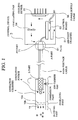
- Fig. 1 is a model diagram which shows the overall construction of the ionized gas current emission type dust-free ionizer of the present embodiment.
- 1 indicates a cylindrical ionization chamber (hereafter referred to as a "chamber"); this chamber is constructed from a metal such as aluminum, stainless steel or the like, or a resin such as polyvinyl chloride or the like.
- this chamber 1 is constructed from an ionization part, a shielding part and a blowing part.
- An ionization source 4 is disposed in the interior of the chamber 1; this ionization source 4 is connected via a high-voltage cable 6 to a control device 5 which controls the quantity of ions generated by the ionization source 4.
- the ionized gas current emission type dust-free ionizer of the present invention has characterizing features in the construction of the control device 5, the construction of the connecting part (part A in Fig. 1) between the control device 5 and high-voltage cable 6, and connecting part (part B in Fig. 1) between the abovementioned ionization source 4 and high-voltage cable 6.
- the constructions of these respective parts will be described in detail below.
- the control device 5 is constructed from an air-tight chamber 51 which has an explosion-proof function. Furthermore, a control board 53 which is a control part that is used to cause the generation of soft X-rays, a low-energy electron beam or ultraviolet radiation from the abovementioned ionization source 4, a circulating fan 54 which circulates cooled air or the like, and a cooling device 55 which controls the interior of the device to a constant temperature, are installed inside the control device 5. Furthermore, a power supply cable 56 is connected to the abovementioned control board 53, and the control device 5 is thus adapted so that this device can be connected to an explosion-proof socket (not shown in the figures) installed on the outside. In the present embodiment, furthermore, the abovementioned cooling device 55 is constructed (for example) by attaching a Peltier element (thermoelectric refrigerating element) to an aluminum heat dissipating plate.
- a Peltier element thermoelectric refrigerating element
- Fig. 2 (A) is an enlarged sectional view which shows the construction of the connecting part (part A in Fig. 1) between the abovementioned control device 5 and the high-voltage cable 6. Furthermore, as is described below, this connecting part has explosion-proof specifications.
- a plug 61 is attached to the tip end portion of the high-voltage cable 6; thus, the high-voltage cable 6 is adapted so that this cable can be detachably connected to a socket 71 disposed in the side wall of the control device 5. Furthermore, the abovementioned plug 61 has a three-core structure, and electrodes 63 are attached to the tip ends of electrode supporting parts 62 that have a specified length "L". Furthermore, a cap nut 65 which has a screw part 64 formed on the inside wall is attached to the outside of the base part 61a of the abovementioned plug 61 so that this nut can rotate.
- insertion holes 72 which engage with the electrode supporting parts 62 that are formed on the abovementioned plug 61 are formed in the socket 71 that is disposed in the side wall of the control device 5, and electrodes 73 that are connected with the electrodes 63 on the side of the abovementioned plug are formed in the deepest parts of these insertion holes 72. Furthermore, a screw part 74 is formed on the outer circumferential surface of the flange part 71a of the socket 71, and the device is adapted so that [this screw part 74] engages with the screw part 64 of the cap nut 65 attached to the abovementioned plug 61.
- the length of the insertion holes 72 is set as "L" in correspondence to the electrode supporting parts 62 on the plug side, and this length "L” is set so that the attachment and detachment of both sets of electrodes can be performed in air-tight spaces constructed by the electrode supporting parts 62 of the plug 61 and the insertion holes 72 of the socket 71.
- packing 66 such as O-rings or the like may be disposed on the base end portions of the electrode supporting parts 62 in order to maintain the air-tightness of the connecting part between the plug 61 and the socket 71.
- the connecting part (part B in Fig. 1) between the ionization source 4 and the high-voltage cable 6 is constructed by causing a pipe 41 made of a resin which has electrical insulating properties such as a polyvinyl chloride, polypropylene, acrylic or the like through the side surface of the chamber 1, and filling the interior of this pipe with an insulating resin 42 such as an epoxy resin or the like.
- a slender tube (not shown in the figures) is connected to the side end portion (right side end portion in the figure) of the chamber 1 via a tube fitting 2, and the device is thus adapted so that the air inside the chamber that is the object of de-charging, or a non-reactive gas such as high-purity N 2 gas or the like (hereafter referred to as the "ion carrier gas”) can be supplied to the interior of the chamber 1 via this tube.
- the term "high-purity N 2 gas” refers to N 2 gas which contains enough oxygen or water vapor to form negative ions, and which has an oxygen concentration (approximately 5% or less) that does not generate ozone.
- an ionization source 4 is disposed near the installation position of the tube fitting 2 inside the chamber 1. Moreover, an ion generating device is formed by this ionization source 4 and the abovementioned control device 5.
- the abovementioned ionization source 4 comprises the generating part of a soft X-ray generating device, the generating part of a low-energy electron beam generating device, the generating part of an ultraviolet radiation generating device or the like, and is adapted so that this ionization source ionizes the ion carrier gas'that flows through the interior of the chamber 1.
- the shielding part of the chamber 1 is formed by two punched plates 10a and 10b in which numerous fine holes 11 with a diameter of approximately 3 ⁇ are formed. These two punched plates 10a and 10b are separated from each other by a distance of approximately 3 mm, and are disposed in shifted positions so that the fine holes 11 do not overlap.
- the tip end portion of the chamber 1 is opened; this part is disposed in the vicinity of the charged body that is the object of de-charging, and is adapted so that the positive and negative ions generated in the abovementioned ion generating device are fed toward this charged body.
- Soft X-rays are extremely weak X-rays with an energy of approximately 3 to 9.5 keV.
- a low-energy electron beam is an electron beam (soft electron beam) which is extracted at a low operating voltage of several tens of kilovolts by means of (for example) a super-compact electron beam irradiation tube manufactured by Ushio Denki K.K. or the like. This electron beam has a travel distance of only about 5 cm in air, and ionizes air or gases in this region.
- the ultraviolet radiation generated by an ultraviolet radiation generating device is short-wavelength radiation with a wavelength of 400 nm or less, and an output power of approximately 30 W.
- the ionization source 4 is a soft X-ray generating part
- either air or a non-reactive gas may be used as the ion carrier gas that is supplied to the chamber 1; however, in cases where the ionization source 4 is a low-energy electron beam generating part or ultraviolet radiation generating part, it is desirable to a non-reactive gas whose oxygen content is small enough that ozone is not generated, such as high-purity N 2 gas or the like, as the ion carrier gas.
- the ionized gas current emission type dust-free ionizer of the present embodiment uses the generating part of a soft X-ray generating device, the generating part of a low-energy electron beam generating device, the generating part of an ultraviolet radiation generating device or the like as an ionization source without using a corona discharge that might be a cause of ignition as this ionization source, the ignition of combustible substances such as organic solvents or the like can be prevented.
- a cooling device consisting of a Peltier element (thermoelectric cooling element) or the like is disposed inside the control device 5 that controls the quantity of ions generated by the abovementioned ionization source, so that heat radiating from the control board and heat sources disposed inside the control device, thus making it possible to control the interior of the device to a constant temperature; accordingly, the control device can be formed with an air-tight structure. As a result, the ignition of combustible substances such as organic solvents or the like by the control board and heat sources disposed inside the device can be prevented.
- the connecting part between the high-voltage cable 6 and the control device 5 has an explosion-proof structure of the type shown in Figure 2
- the attachment or detachment of the electrodes can be performed in an air-tight space formed by the electrode supporting parts 62 of the plug 61 and the insertion holes 72 of the socket 71; accordingly, the ignition of combustible substances such as organic solvents or the like caused by discharges during the attachment or detachment of the plug can be prevented.
- the connecting part between the ionization source 4 and the high-voltage cable 6 also has an explosion-proof structure of the type shown in Figure 1, the ignition of combustible substances such as organic solvents or the like in this connecting part can also be prevented.
- the ion carrier gas that is supplied to the chamber 1 via a tube (not shown in the figures) and the tube fitting 2 is converted into positive and negative ions by irradiation with soft X-rays, a low-energy electron beam, ultraviolet radiation or the like by the ionization source 4 contained in the chamber 1. Furthermore, these positive and negative ions pass through the shielding part installed on the downstream side of the ionization part, and are supplied to the charged body that constitutes the object of de-charging from the tip end portion of the chamber 1, so that the positive and negative charges of opposite polarity on the charged body can be respectively neutralized.
- the ionization source 4 is a soft X-ray generating part
- there is no generation of ozone regardless of whether air or a non-reactive gas is used as the ion carrier gas.
- dust such as the scattering of electrode materials or deposition and re-scattering of impurities in the air, and there is likewise no generation of electromagnetic noise.
- the ionization source 4 is a low-energy electron beam or ultraviolet radiation generating part
- a non-reactive gas whose oxygen content is small enough that there is no generation of ozone, such as high-purity N 2 gas or the like, is used as the ion carrier gas there is no generation of ozone, no generation of dust and no generation of electromagnetic noise during ionization.
- the disturbance of the gas current from the chamber blowing port can be reduced; accordingly, the following merit is also obtained: namely, the decrease in the quantity of ions caused by disturbance of the gas current can be ameliorated.
- the ionization source 4 and the control device 5 constituting the power supply part and control part of this ionization source 4 are installed separately with a high-voltage cable interposed, and since only the ionization source 4 is disposed inside the chamber 1, the internal diameter of the chamber 1 can be reduced; accordingly, the following merits can be obtained: namely, ions can be generated in an extremely narrow space, and de-charging can be performed even in the case of a narrow space such as (for example) the gaps between glass substrates accommodated inside a cassette.
- the ionized gas current emission type dust-free ionizer of the present embodiment makes it possible to obtain an ionizer which allows countermeasures against static electricity to be taken in a narrow space without generating ozone, electromagnetic noise or dust, and which can be used in explosion-proof facilities and equipment.
- the present embodiment is a modification in which the construction of the shielding part of the abovementioned first embodiment is altered.
- the shielding part of the chamber 1 is constructed from two semicircular partition walls 7, 7; these partition walls 7, 7 are alternately formed on the upper part and lower part of the chamber 1 so that a fixed gap is left.
- the ionization source 4 is a soft X-ray generating part or low-energy electron beam generating part
- the system is adapted so that the linearly advancing soft X-rays or electron beam electrons strike the partition walls 7, 7, thus providing a construction in which shielding is provided so that these soft X-rays or electrons do not leak to the outside.
- the ionization source 4 is an ultraviolet radiation generating part, this shielding part is unnecessary.
- the remaining construction is the same as in the abovementioned first embodiment; accordingly, a description is omitted.
- the ionized gas current emission type dust-free ionizer of the present embodiment which has the construction described above, has the same effects and merits as the abovementioned first embodiment; this ionizer can be used in explosion-proof facilities and equipment, and can form the area on the downstream side of the ionization part of the chamber 1 into a shielding structure by means of a simple construction.
- the present embodiment is a modification in which the construction of the blowing part of the abovementioned first embodiment is altered. Furthermore, it goes without saying that the blowing part of the present embodiment can also be applied to the abovementioned second embodiment.
- a nozzle 20 which is used to cause jetting of the ionized gas current is disposed on the downstream side of the shielding part of the chamber 1.
- a nozzle 216, flat nozzle 920, air curtain 302-306, air knife 392-396 or the like manufactured by SILVENT Co. can be used as the abovementioned nozzle 20.
- the same effects and merits as those of the abovementioned first embodiment or second embodiment can be obtained; moreover, since a nozzle 20 which has a desired shape and size is attached to the blowing part, the ionized gas current can be blown onto the charged body at a high velocity, so that dirt or the like adhering to the charged body can be removed with a high efficiency while the charged body is de-charged.
- nozzles 20 By selecting various types of nozzles 20, it is possible to broaden the ionized gas current at a wide angle in a conical shape, or to spread the ionized gas current into the form of an air curtain; accordingly, the ionized gas current can be controlled in accordance with the object of de-charging. Furthermore, by using a nozzle that allows adjustment of the degree of opening, it is easily possible to alter the jet velocity of the ionized gas current.
- the present embodiment is a modification in which the construction of the blowing part of the abovementioned third embodiment is further altered.
- a flexible hose 30 is attached to the blowing part of the chamber 1, and a nozzle 31 is attached to the tip end of this flexible hose 30.
- a nozzle 216, flat nozzle 920, air curtain 302-306, air knife 392-396 or the like manufactured by SILVENT Co. can be used as the abovementioned nozzle 31.
- this flexible hose 30 differs from a vinyl tube or the like in that this hose has a structure can maintain a set shape.
- a flexible hose 30 is attached to the blowing part and a nozzle 31 is further attached to the tip end of this flexible hose 30, not only can the same effects and merits as those of the abovementioned first through third embodiments be obtained, but it is also possible blow the ionized gas current onto the charged body at a high velocity, so that dirt or the like adhering to the charged body can be removed with a high efficiency while the charged body is de-charged.
- nozzles 31 By selecting various types of nozzles 31, it is possible to broaden the ionized gas current at a wide angle in a conical shape, or to spread the ionized gas current into the form of an air curtain; accordingly, the ionized gas current can be controlled in accordance with the object of de-charging. Furthermore, by using a nozzle that allows adjustment of the degree of opening, it is easily possible to alter the jet velocity of the ionized gas current.
- the present embodiment is an embodiment in which the shielding part and blowing part are constructed as an integral unit.
- one or a plurality of openings (holes with a diameter of approximately 1 ⁇ ) 40 which are of a size that can block X-rays or the like are formed (in accordance with the object of de-charging) in a portion of the chamber (e. g., side surface) on the downstream side of the ionization source 4. Furthermore, in the present embodiment, these openings 40 function as a shielding part and a blowing part.
- the ionized gas current emission type dust-free ionizer of the present embodiment which has the construction described above, since a plurality of openings which are of a size that can block X-rays are formed in a portion of the chamber on the downstream side of the ionization source 4, the jetting of an ionized gas current toward the object of de-charging can be accomplished simultaneously with shielding. Furthermore, as will be described below, the present embodiment is especially effective in cases where de-charging is performed by blowing an ionized gas current into the deep portions of narrow spaces such as the gaps between glass substrates in a cassette or the like.
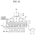
- the ionized gas current emission type dust-free ionizer of the present embodiment has characterizing features in the construction of the blowing port. Specifically, as is shown in Fig. 7, the blowing port 81 in the present embodiment is formed in a cylindrical or prismatic shape, and a chamber 82 and duct 83 are connected to the upstream side of this blowing port 81. Furthermore, the duct 83 comprises piping which is used to supply air or a non-reactive gas such as high-purity N 2 gas or the like (hereafter referred to as the "ion carrier gas") to the object of de-charging in an explosion-proof facility via the abovementioned chamber 82 and blowing port 81.
- a non-reactive gas such as high-purity N 2 gas or the like
- the chamber 82 is formed (for example) in the shape of a cone or square pyramid so that the cross-sectional area on the downstream side is larger than that on the upstream side, and the end portion on the upstream side is connected to the abovementioned duct 83, while the end portion on the downstream side is connected to the abovementioned blowing port 81. Furthermore, it goes without saying that the chamber 82 and blowing port 81 can also be constructed as an integral unit.
- a shielding part 84 is disposed in the vicinity of the tip end portion of the abovementioned blowing port 81.
- this shielding part 84 is constructed from two punched plates 86a and 86b with a thickness of 1 mm in which numerous fine holes 85 with a diameter of approximately 5 mm ⁇ and an opening pitch of approximately 12 mm are formed. These two punched plates 86a and 86b are separated from each other by a distance of approximately 3 mm, and are disposed in positions that are shifted so that the abovementioned fine holes 85 do not overlap.
- the tip end portion of the blowing port 81 is open, and is disposed in the vicinity of the charged body S; the system is thus adapted so that positive and negative ions generated in the ion generating device are fed toward this charged body S.
- an ion generating device is disposed in the side portion of the abovementioned blowing port 81.
- This ion generating device is constructed from an ionization source 4 which is disposed in the side portion of the blowing port 81, and a control device 5 which controls the quantity of ions generated by this ionization source 4.
- this control device 5 is disposed on the outside of the blowing port 81, and consists of a power supply part and control part which are used to generate soft X-rays or ultraviolet radiation from the ionization source; the control device 5 is connected to the ionization source 4 by a high-voltage cable 6.
- this control device 5 the construction of the connecting part between the high-voltage cable 6 and the control device 5, and the construction of the connecting part between the ionization source 4 and the high-voltage cable 6, are the same as in the abovementioned first embodiment; accordingly, a description is omitted.
- this ionizer can be used in explosion-proof facilities and equipment; furthermore, since the ionization source 4 is contained internally in the vicinity of the outlet part of the blowing port 81, the ion carrier gas can be ionized in the vicinity of the blowing port 81, so that ionized air or the like can be supplied to the desired object of de-charging. Furthermore, since the ionization source 4 is contained internally in the side portion of the blowing port 81, and irradiation with radiation such as soft X-rays or the like is performed horizontally with the blowing port, a broad range can be covered by a single ionization source.
- the ionization source 4 is contained internally in the vicinity of the outlet part of the blowing port 81, so that the distance from the ionization source 4 to the outlet of the blowing port is short, so that the following merit is also obtained: namely, there is little decrease in the ions due to the re-coupling of positive and negative ions.
- This embodiment is a modification in which the installation position of the ionization source of the abovementioned sixth embodiment is altered.
- the ionization source 4 is disposed in the central portion of a chamber 82 which is formed in the shape of a cone or square pyramid.
- the remaining construction is the same as in the abovementioned sixth embodiment; accordingly, a description is omitted.
- the ionization source that can be disposed as shown in Fig. 8 is a soft X-ray or ultraviolet radiation generating part.
- the ionized gas current emission type dust-free ionizer of the present embodiment which has the construction described above, not only can the same effects and merits as in the abovementioned sixth embodiment be obtained, but it also possible to perform ionization over a broad range with a small ionization source in the case of an ionization source that can emit soft X-rays or the like over a broad angle. Accordingly, since the ionization efficiency is good, and the quantity of ions generated is increased, the de-charging performance is improved. Furthermore, the angle of incidence of the radiation on the shielding plates is greater than in cases where irradiation is performed horizontally in the vicinity of the shielding plates; accordingly, shielding is facilitated, and shielding plate with vertical holes or the like are unnecessary.
- This embodiment is a modification of the abovementioned sixth embodiment, and indicates a case in which an HEPA filter or ULPA filter is disposed on the upstream side of the blowing port.
- a laminar flow forming filter 91 such as a HEPA filter, ULPA filter or the like is disposed on the upstream side of the blowing port 81, and the system is adapted so that the ion carrier gas that is fed in via the duct 83 and chamber 82 can be formed into a gas current that has a uniform flow velocity distribution over the entire surface of the blowing port 81.
- the ionization source 4 is disposed in the vicinity of the side wall portion between the abovementioned laminar flow forming filter 91 and the shielding part 84.
- the remaining construction is the same as in the abovementioned sixth embodiment; accordingly, a description is omitted.
- the ionized gas current emission type dust-free ionizer of the present embodiment which has the abovementioned construction, not only can the same effects and merits as those of the abovementioned sixth embodiment be obtained, but it is also possible to form the ion carrier gas that is fed in from the chamber 82 into a laminar flow, since a laminar flow forming filter 91 is disposed on the upstream side of the blowing port 81.
- the ionized gas current emission type dust-free ionizer of the present embodiment is a modification of the abovementioned sixth embodiment.
- a laminar flow forming filter 91 such as a HEPA filter, ULPA filter or the like is disposed on the upstream side of the blowing port 81
- an aluminum honeycomb 92 which has vertical holes is disposed on the upstream side of the two punched plates 86a and 86b disposed in the shielding part 84 of the blowing port 81.
- a sleeve-equipped punched plate 93 such as that shown in Fig. 11 (C) instead of installing an aluminum honeycomb 92 with vertical holes.
- the remaining construction is that same as that of the abovementioned sixth embodiment; accordingly, a description is omitted.
- the ionizer can be used in explosion-proof facilities and equipment; furthermore, since a laminar flow forming filter 91 is disposed on the upstream said of the blowing port 81, the ion carrier gas that is fed in from the chamber 82 can be formed into a laminar flow.
- the present invention is not limited to the embodiments described above; various configurations such as those described below are possible. Specifically, the shapes or attachment positions and methods of respective concrete members may be appropriately altered.
- the shape of the shielding part is not limited to the punched plates indicated in the respective embodiments described above; any shape that is capable of preventing the leakage of linearly advancing soft X-rays, low-energy electron beam electrons or the like to the outside, and that can carry the positive and negative ions that are generated, may be used.
- the ionization source 4 is not limited to soft X-rays, a low-energy electron beam or ultraviolet radiation; other electromagnetic waves, beams or the like may be used as long as these sources do not generate ozone, dust or electromagnetic noise as a result of ionization.
- a construction in which an air supply fan 94 is incorporated may be applied.
- the present invention can provide an ionized gas current emission type dust-free ionizer which makes it possible to take countermeasures against static electricity in a narrow space without causing the generation of ozone, electromagnetic noise, dust or the like, and which can also be used in explosion-proof facilities and equipment.
Landscapes
- Health & Medical Sciences (AREA)
- General Health & Medical Sciences (AREA)
- Toxicology (AREA)
- Elimination Of Static Electricity (AREA)
Abstract
Description
Claims (12)
- An ionized gas current emission type dust-free ionizer which comprises a chamber having an ionization part that ionizes a portion of an ion carrier gas that is supplied to the interior of this chamber, and a blowing part that feeds the ion carrier gas toward a charged body, and in which said ionization part is constructed from an ionization source that is contained in said chamber, and a control device which is disposed outside said chamber and which controls the quantity of ions generated by said ionization source via a high-voltage cable, this ionizer being characterized in that:said ionization source is either the generating part of a soft X-ray generating device, the generating part of a low-energy electron beam generating device, or the generating part of an ultraviolet radiation generating device; andsaid control device, the connecting part between said control device and the high-voltage cable, and the connecting part between said ionization source and the high-voltage cable, have an explosion-proof structure.
- The ionized gas current emission type dust-free ionizer according to claim 1, characterized in that said control device has an air-tight structure, and comprises cooling means capable of maintaining the interior of the device at a constant temperature.
- The ionized gas current emission type dust-free ionizer according to claim 2, characterized in that said cooling means are constructed from a thermoelectric refrigerating element.
- The ionized gas current emission type dust-free ionizer according to any of claims 1 through 3, characterized in that:the connecting part between said high-voltage cable and control device is constructed from a plug and socket that can be attached and detached, electrode supporting parts which have a specified length are disposed in said plug, electrodes are disposed on the tip end portions of these electrode supporting parts, insertion holes into which said electrode supporting parts are inserted are formed in said socket, electrodes are disposed in the innermost parts of these insertion holes;the electrical connection between said high-voltage cable and control device is accomplished by electrodes which are disposed on the tip end of said plug and electrodes which are disposed in the innermost parts of the insertion holes of the socket; andsaid plug and socket are adapted so that the attachment and detachment of said electrodes can be performed in a state in which an air-tight state between the electrode supporting parts of said plug and the insertion holes of the socket is maintained.
- The ionized gas current emission type dust-free ionizer according to any one of claims 1 through 4, characterized in that the connecting part between said ionization source and high-voltage cable is formed by a tubular resin that has insulating properties, and an insulating resin with which the interior of said tubular resin is filled.
- The ionized gas current emission type dust-free ionizer according to any one of claims 1 through 5, characterized in that a shielding part which is used to block the soft X-rays or low-energy electron beam generated by said ionization source is formed on the downstream side of the ionization part inside said chamber.
- The ionized gas current emission type dust-free ionizer according to claim 6, characterized in that said shielding part is constructed from a plurality of partition walls which are alternately disposed on the inside walls of said chamber with a specified gap.
- The ionized gas current emission type dust-free ionizer according to claim 6, characterized in that said shielding part is constructed from at least two shielding plates in which a plurality of fine holes are formed, and said shielding plates are disposed so that said fine holes do not overlap.
- The ionized gas current emission type dust-free ionizer according to any one of claims 1 through 8, characterized in that said blowing part is constructed from a nozzle with a specified shape which is attached to the open end of said chamber.
- The ionized gas current emission type dust-free ionizer according to any one of claims 1 through 8, characterized in that said blowing part is constructed from a flexible hose attached to the open end of said chamber, and a nozzle with a specified shape which is attached to the tip end thereof.
- The ionized gas current emission type dust-free ionizer according to any one of claims 1 through 8, characterized in that a plurality of openings are formed in one portion of the downstream-side side surface of said chamber, and the chanber is adapted so that the ion carrier gas is supplied to the charged body via these openings.
- The ionized gas current emission type dust-free ionizer according to any one of claims 1 through 8, characterized in that a laminar flow forming filter is disposed on the upstream side of said blowing part.
Priority Applications (1)
| Application Number | Priority Date | Filing Date | Title |
|---|---|---|---|
| EP08100581A EP1947915A2 (en) | 2001-05-29 | 2002-05-28 | Ionized air flow discharge type non-dusting ionizer |
Applications Claiming Priority (3)
| Application Number | Priority Date | Filing Date | Title |
|---|---|---|---|
| JP2001161060A JP4738636B2 (en) | 2001-05-29 | 2001-05-29 | Explosion-proof dustless ionizer |
| JP2001161060 | 2001-05-29 | ||
| PCT/JP2002/005136 WO2002098188A1 (en) | 2001-05-29 | 2002-05-28 | Ionized air flow discharge type non-dusting ionizer |
Related Child Applications (1)
| Application Number | Title | Priority Date | Filing Date |
|---|---|---|---|
| EP08100581A Division EP1947915A2 (en) | 2001-05-29 | 2002-05-28 | Ionized air flow discharge type non-dusting ionizer |
Publications (3)
| Publication Number | Publication Date |
|---|---|
| EP1397030A1 true EP1397030A1 (en) | 2004-03-10 |
| EP1397030A4 EP1397030A4 (en) | 2004-09-01 |
| EP1397030B1 EP1397030B1 (en) | 2008-03-12 |
Family
ID=19004394
Family Applications (2)
| Application Number | Title | Priority Date | Filing Date |
|---|---|---|---|
| EP08100581A Withdrawn EP1947915A2 (en) | 2001-05-29 | 2002-05-28 | Ionized air flow discharge type non-dusting ionizer |
| EP02730725A Expired - Lifetime EP1397030B1 (en) | 2001-05-29 | 2002-05-28 | IONIZED AIR FLOW DISCHARGE TYPE NON−DUSTING IONIZER |
Family Applications Before (1)
| Application Number | Title | Priority Date | Filing Date |
|---|---|---|---|
| EP08100581A Withdrawn EP1947915A2 (en) | 2001-05-29 | 2002-05-28 | Ionized air flow discharge type non-dusting ionizer |
Country Status (8)
| Country | Link |
|---|---|
| US (2) | US7126807B2 (en) |
| EP (2) | EP1947915A2 (en) |
| JP (1) | JP4738636B2 (en) |
| KR (1) | KR100912981B1 (en) |
| CN (1) | CN1301633C (en) |
| DE (1) | DE60225548T2 (en) |
| TW (1) | TWI242394B (en) |
| WO (1) | WO2002098188A1 (en) |
Cited By (9)
| Publication number | Priority date | Publication date | Assignee | Title |
|---|---|---|---|---|
| WO2008007084A1 (en) * | 2006-07-12 | 2008-01-17 | Kidde Ip Holdings Limited | Smoke detector and ionisation apparatus |
| EP2036856A3 (en) * | 2007-09-04 | 2009-08-19 | Mitsubishi Materials Corporation | Clean bench and method of producing raw material for single crystal silicon |
| TWI401999B (en) * | 2006-04-11 | 2013-07-11 | Takasago Thermal Engineering | A soft X-ray generating device and a de-energizing device |
| TWI453351B (en) * | 2009-06-25 | 2014-09-21 | ||
| US9053892B2 (en) | 2010-12-30 | 2015-06-09 | Walter Kidde Portable Equipment, Inc. | Ionization device |
| WO2024123564A1 (en) * | 2022-12-08 | 2024-06-13 | Hamamatsu Photonics K.K. | Inductively coupled plasma light source with direct gas injection |
| US12156322B2 (en) | 2022-12-08 | 2024-11-26 | Hamamatsu Photonics K.K. | Inductively coupled plasma light source with switched power supply |
| US12578076B2 (en) | 2023-06-05 | 2026-03-17 | Hamamatsu Photonics K.K. | Dual-output laser-driven light source |
| US12674995B2 (en) | 2021-01-21 | 2026-07-07 | Hamamatsu Photonics K.K. | Spectrally shaped light source |
Families Citing this family (34)
| Publication number | Priority date | Publication date | Assignee | Title |
|---|---|---|---|---|
| JP2005005172A (en) * | 2003-06-13 | 2005-01-06 | Genesis Technology Inc | Soft X-ray irradiation apparatus, semiconductor assembly apparatus, and inspection apparatus |
| WO2004113984A1 (en) * | 2003-06-26 | 2004-12-29 | Ls Cable Ltd. | Method and apparatus for installing an optical-fiber unit capable of removing static electricity |
| JP4446755B2 (en) * | 2004-01-29 | 2010-04-07 | トヨタ自動車株式会社 | Static eliminator |
| WO2005101923A1 (en) * | 2004-03-30 | 2005-10-27 | Kansai Technology Licensing Organization Co., Ltd. | X-ray generator employing hemimorphy crystal and ozone generator employing it |
| JP4594111B2 (en) * | 2005-01-17 | 2010-12-08 | 株式会社コガネイ | Static eliminator and discharge module |
| JP4369386B2 (en) * | 2005-03-25 | 2009-11-18 | セイコーエプソン株式会社 | Soft X-ray static eliminator |
| KR100680760B1 (en) * | 2005-04-19 | 2007-02-08 | (주)선재하이테크 | Flexible X-ray Ionizer |
| US7458677B2 (en) * | 2006-06-20 | 2008-12-02 | Eastman Kodak Company | Reduction of turbulence within printing region of inkjet printer heads |
| KR100676527B1 (en) * | 2006-10-16 | 2007-01-30 | (주)선재하이테크 | Charge removal method of ionizer and charged object using soft x-ray |
| JP4941415B2 (en) * | 2007-09-04 | 2012-05-30 | 三菱マテリアル株式会社 | Clean bench |
| US7796727B1 (en) | 2008-03-26 | 2010-09-14 | Tsi, Incorporated | Aerosol charge conditioner |
| JP4404948B1 (en) | 2008-08-28 | 2010-01-27 | シャープ株式会社 | Ion generator |
| WO2010023979A1 (en) * | 2008-08-28 | 2010-03-04 | シャープ株式会社 | Ion detection device and ion generation device |
| JP5322666B2 (en) * | 2008-11-27 | 2013-10-23 | 株式会社Trinc | Ozone-less static eliminator |
| KR101268175B1 (en) | 2009-03-26 | 2013-05-27 | 샤프 가부시키가이샤 | Ion-generation device |
| CN102136681B (en) * | 2010-01-26 | 2013-01-02 | 罗莎国际有限公司 | Self-cooled ionized air generating device |
| JP5485056B2 (en) * | 2010-07-21 | 2014-05-07 | 東京エレクトロン株式会社 | Ion supply apparatus and processing system for target object provided with the same |
| WO2012064979A1 (en) * | 2010-11-10 | 2012-05-18 | Tessera, Inc. | Electronic system with ehd air mover ventilation path isolated from internal air plenum |
| JP5937918B2 (en) * | 2012-08-08 | 2016-06-22 | シャープ株式会社 | Ion generator and static eliminator provided with the same |
| US20140284204A1 (en) * | 2013-03-22 | 2014-09-25 | Airmodus Oy | Method and device for ionizing particles of a sample gas glow |
| CN103353142A (en) * | 2013-05-30 | 2013-10-16 | 苏州华达仪器设备有限公司 | Electrostatic neutralization device for air |
| US9839106B2 (en) | 2014-07-23 | 2017-12-05 | Moxtek, Inc. | Flat-panel-display, bottom-side, electrostatic-dissipation |
| US9839107B2 (en) | 2014-07-23 | 2017-12-05 | Moxtek, Inc. | Flowing-fluid X-ray induced ionic electrostatic dissipation |
| US9826610B2 (en) | 2014-07-23 | 2017-11-21 | Moxtek, Inc. | Electrostatic-dissipation device |
| US9779847B2 (en) | 2014-07-23 | 2017-10-03 | Moxtek, Inc. | Spark gap X-ray source |
| US9084334B1 (en) | 2014-11-10 | 2015-07-14 | Illinois Tool Works Inc. | Balanced barrier discharge neutralization in variable pressure environments |
| WO2016077056A1 (en) * | 2014-11-13 | 2016-05-19 | Moxtek, Inc. | Electrostatic-dissipation device |
| US10524341B2 (en) | 2015-05-08 | 2019-12-31 | Moxtek, Inc. | Flowing-fluid X-ray induced ionic electrostatic dissipation |
| JP6655418B2 (en) | 2016-02-17 | 2020-02-26 | 株式会社Screenホールディングス | Substrate processing apparatus and substrate processing method |
| EP3504007B1 (en) * | 2016-08-26 | 2022-01-12 | Plasma Shield Limited | A gas purifying apparatus |
| KR102020911B1 (en) * | 2018-02-26 | 2019-09-11 | (주)선재하이테크 | In-line Type Photo Ionizer |
| DE102022115343B3 (en) * | 2022-06-21 | 2023-10-05 | Miele & Cie. Kg | Cooking appliance muffle for a cooking appliance, cooking appliance and method for operating a cooking appliance |
| KR102552934B1 (en) * | 2023-02-06 | 2023-07-07 | 주식회사 저스템 | High vacuum static electricity removing device with baffle structure |
| KR102677916B1 (en) * | 2023-05-02 | 2024-06-25 | 주식회사 저스템 | Vacuum static electricity removing device |
Family Cites Families (53)
| Publication number | Priority date | Publication date | Assignee | Title |
|---|---|---|---|---|
| GB466579A (en) * | 1935-12-03 | 1937-05-31 | Cecil Richard Almas Chadfield | Improvements in or relating to means for discharging electricity from materials and machinery |
| US3128378A (en) * | 1960-10-04 | 1964-04-07 | Dynamics Corp America | Negative ion generator using an ultraviolet source to irradiate electrically conductive material |
| GB1380827A (en) | 1971-03-31 | 1975-01-15 | Cierva J J De | Electrostatic charge control systems |
| US3745413A (en) * | 1971-12-16 | 1973-07-10 | Eastman Kodak Co | Ionizing apparatus |
| US4166664A (en) * | 1975-01-24 | 1979-09-04 | Amp Incorporated | High voltage quick disconnect electrical connector assembly |
| US4023071A (en) * | 1975-06-09 | 1977-05-10 | Fussell Gerald W | Transient and surge protection apparatus |
| FR2360199A1 (en) * | 1976-07-27 | 1978-02-24 | Pellin Henri | NEGATIVE IONIZER |
| US4180841A (en) * | 1977-11-21 | 1979-12-25 | Westinghouse Electric Corp. | Ground fault circuit interrupter with grounded neutral protection |
| US4163650A (en) * | 1978-07-24 | 1979-08-07 | Tepco, Incorporated | Portable electronic precipitator |
| JPS58122426A (en) * | 1982-01-14 | 1983-07-21 | Tokyo Tatsuno Co Ltd | Storage box for electronic parts |
| US4630163A (en) * | 1982-09-02 | 1986-12-16 | Efi Corporation | Method and apparatus for a transient-suppression network |
| US4587588A (en) * | 1984-03-02 | 1986-05-06 | Perma Power Electronics, Inc. | Power line transient surge suppressor |
| DE3543096A1 (en) * | 1984-12-05 | 1986-06-05 | Olympus Optical Co., Ltd., Tokio/Tokyo | DEVICE FOR THE CRUSHING OF STONES, LIKE KIDNEY AND GALLET STONES OR THE LIKE |
| JPS62171167A (en) * | 1986-01-23 | 1987-07-28 | Mitsubishi Electric Corp | Manufacture of solar cell |
| JPS62171167U (en) * | 1986-04-21 | 1987-10-30 | ||
| JPH0763649B2 (en) * | 1987-05-26 | 1995-07-12 | ミドリ安全工業株式会社 | Air purifier with static eliminator |
| US4825090A (en) * | 1988-02-09 | 1989-04-25 | Grabis Dietrich W | Shielding membrane |
| US4827371A (en) * | 1988-04-04 | 1989-05-02 | Ion Systems, Inc. | Method and apparatus for ionizing gas with point of use ion flow delivery |
| US4901183A (en) * | 1988-08-29 | 1990-02-13 | World Products, Inc. | Surge protection device |
| JPH0734334B2 (en) * | 1988-10-20 | 1995-04-12 | 株式会社戸上電機製作所 | Airtight electrical equipment |
| JPH0421832A (en) | 1990-05-16 | 1992-01-24 | Canon Inc | Device for suppressing image blur |
| JP2977098B2 (en) * | 1990-08-31 | 1999-11-10 | 忠弘 大見 | Charged material neutralization device |
| JP2542744B2 (en) | 1991-02-05 | 1996-10-09 | 株式会社東芝 | Oil mist treatment device for bearing lubrication device |
| US5177657A (en) * | 1991-05-16 | 1993-01-05 | Felchar Manufacturing Corporation | Ground fault interruptor circuit with electronic latch |
| US5256204A (en) * | 1991-12-13 | 1993-10-26 | United Microelectronics Corporation | Single semiconductor water transfer method and manufacturing system |
| US5448443A (en) * | 1992-07-29 | 1995-09-05 | Suvon Associates | Power conditioning device and method |
| JP2981702B2 (en) * | 1992-08-27 | 1999-11-22 | 愛三工業株式会社 | Ignition coil for internal combustion engine |
| JP3115731B2 (en) | 1993-03-09 | 2000-12-11 | 高砂熱学工業株式会社 | Air impurity removal equipment |
| JP2677945B2 (en) * | 1993-06-18 | 1997-11-17 | 浜松ホトニクス株式会社 | Ion gas generator |
| JP3198736B2 (en) | 1993-07-14 | 2001-08-13 | 東レ株式会社 | Bobbin holding device and bobbin holder |
| JPH0763649A (en) | 1993-08-27 | 1995-03-10 | Asahi Glass Co Ltd | Apparatus and method for measuring focal length of divergence optical system |
| US5418678A (en) * | 1993-09-02 | 1995-05-23 | Hubbell Incorporated | Manually set ground fault circuit interrupter |
| JPH07211483A (en) * | 1994-01-17 | 1995-08-11 | Rion Denshi Kk | Static eliminator |
| JP3696904B2 (en) * | 1994-08-02 | 2005-09-21 | シシド静電気株式会社 | Static eliminator using soft X-ray |
| US5617284A (en) * | 1994-08-05 | 1997-04-01 | Paradise; Rick | Power surge protection apparatus and method |
| JP2668512B2 (en) * | 1994-10-24 | 1997-10-27 | 株式会社レヨーン工業 | Static electricity removal device for object surface by soft X-ray |
| JPH08162284A (en) | 1994-12-09 | 1996-06-21 | Fuiisa Kk | Static eliminator |
| JPH08190993A (en) * | 1995-01-09 | 1996-07-23 | Ceratec:Kk | Radiation type static eliminator and radiation type static erasing method by radiation type static eliminator |
| US5555150A (en) * | 1995-04-19 | 1996-09-10 | Lutron Electronics Co., Inc. | Surge suppression system |
| JP3609893B2 (en) * | 1996-02-05 | 2005-01-12 | 大日本スクリーン製造株式会社 | Substrate processing equipment |
| JP3611063B2 (en) * | 1996-05-21 | 2005-01-19 | 住友電装株式会社 | Case internal / external connection structure |
| JPH10106789A (en) * | 1996-09-26 | 1998-04-24 | Reyoon Kogyo:Kk | Method and apparatus for removing static electricity from object surface |
| JPH10118573A (en) | 1996-10-21 | 1998-05-12 | Shin Etsu Polymer Co Ltd | Method of separating synthetic resin laminate |
| US6522039B1 (en) * | 1996-12-13 | 2003-02-18 | Illinois Tool Works Inc. | Remote power source for electrostatic paint applicator |
| JPH10302541A (en) * | 1997-04-28 | 1998-11-13 | Bridgestone Corp | Light source device |
| US6040967A (en) * | 1998-08-24 | 2000-03-21 | Leviton Manufacturing Co., Inc. | Reset lockout for circuit interrupting device |
| US6365016B1 (en) * | 1999-03-17 | 2002-04-02 | General Electric Company | Method and apparatus for arc plasma deposition with evaporation of reagents |
| JP4489883B2 (en) | 1999-12-17 | 2010-06-23 | 株式会社テクノ菱和 | Chamber type ion transport ionizer |
| JP3902370B2 (en) | 2000-01-18 | 2007-04-04 | エスペック株式会社 | Heat treatment equipment with static elimination function |
| JP4168160B2 (en) * | 2000-03-10 | 2008-10-22 | 株式会社テクノ菱和 | Static electricity outlet |
| US6671186B2 (en) * | 2001-04-20 | 2003-12-30 | Hewlett-Packard Development Company, L.P. | Electromagnetic interference shield |
| KR100472408B1 (en) * | 2001-11-22 | 2005-03-08 | 주식회사 싸이클로젠 | Method For Preparing Composition For Treating Osteoporosis |
| JP7063649B2 (en) * | 2018-02-08 | 2022-05-09 | 株式会社明治 | Pizza crust and its manufacturing method |
-
2001
- 2001-05-29 JP JP2001161060A patent/JP4738636B2/en not_active Expired - Fee Related
-
2002
- 2002-05-28 TW TW091111344A patent/TWI242394B/en not_active IP Right Cessation
- 2002-05-28 EP EP08100581A patent/EP1947915A2/en not_active Withdrawn
- 2002-05-28 KR KR1020037015508A patent/KR100912981B1/en not_active Expired - Fee Related
- 2002-05-28 US US10/479,353 patent/US7126807B2/en not_active Expired - Fee Related
- 2002-05-28 CN CNB028108604A patent/CN1301633C/en not_active Expired - Fee Related
- 2002-05-28 DE DE60225548T patent/DE60225548T2/en not_active Expired - Lifetime
- 2002-05-28 EP EP02730725A patent/EP1397030B1/en not_active Expired - Lifetime
- 2002-05-28 WO PCT/JP2002/005136 patent/WO2002098188A1/en not_active Ceased
-
2006
- 2006-08-22 US US11/507,917 patent/US7397647B2/en not_active Expired - Fee Related
Cited By (12)
| Publication number | Priority date | Publication date | Assignee | Title |
|---|---|---|---|---|
| TWI401999B (en) * | 2006-04-11 | 2013-07-11 | Takasago Thermal Engineering | A soft X-ray generating device and a de-energizing device |
| WO2008007084A1 (en) * | 2006-07-12 | 2008-01-17 | Kidde Ip Holdings Limited | Smoke detector and ionisation apparatus |
| US8334782B2 (en) | 2006-07-12 | 2012-12-18 | Walter Kidde Portable Equipment, Inc. | Smoke detector and ionisation apparatus |
| EP2036856A3 (en) * | 2007-09-04 | 2009-08-19 | Mitsubishi Materials Corporation | Clean bench and method of producing raw material for single crystal silicon |
| US7976599B2 (en) | 2007-09-04 | 2011-07-12 | Mitsubishi Materials Corporation | Clean bench and method of producing raw material for single crystal silicon |
| US8372372B2 (en) | 2007-09-04 | 2013-02-12 | Mitsubishi Materials Corporation | Clean bench and method of producing raw material for single crystal silicon |
| TWI453351B (en) * | 2009-06-25 | 2014-09-21 | ||
| US9053892B2 (en) | 2010-12-30 | 2015-06-09 | Walter Kidde Portable Equipment, Inc. | Ionization device |
| US12674995B2 (en) | 2021-01-21 | 2026-07-07 | Hamamatsu Photonics K.K. | Spectrally shaped light source |
| WO2024123564A1 (en) * | 2022-12-08 | 2024-06-13 | Hamamatsu Photonics K.K. | Inductively coupled plasma light source with direct gas injection |
| US12156322B2 (en) | 2022-12-08 | 2024-11-26 | Hamamatsu Photonics K.K. | Inductively coupled plasma light source with switched power supply |
| US12578076B2 (en) | 2023-06-05 | 2026-03-17 | Hamamatsu Photonics K.K. | Dual-output laser-driven light source |
Also Published As
| Publication number | Publication date |
|---|---|
| JP2002352997A (en) | 2002-12-06 |
| EP1947915A2 (en) | 2008-07-23 |
| DE60225548D1 (en) | 2008-04-24 |
| WO2002098188A9 (en) | 2003-04-10 |
| KR100912981B1 (en) | 2009-08-20 |
| US20040218315A1 (en) | 2004-11-04 |
| US7126807B2 (en) | 2006-10-24 |
| EP1397030A4 (en) | 2004-09-01 |
| CN1513284A (en) | 2004-07-14 |
| TWI242394B (en) | 2005-10-21 |
| US7397647B2 (en) | 2008-07-08 |
| JP4738636B2 (en) | 2011-08-03 |
| DE60225548T2 (en) | 2009-04-23 |
| WO2002098188A1 (en) | 2002-12-05 |
| CN1301633C (en) | 2007-02-21 |
| KR20040004662A (en) | 2004-01-13 |
| EP1397030B1 (en) | 2008-03-12 |
| US20060279897A1 (en) | 2006-12-14 |
Similar Documents
| Publication | Publication Date | Title |
|---|---|---|
| EP1397030B1 (en) | IONIZED AIR FLOW DISCHARGE TYPE NON−DUSTING IONIZER | |
| JP2880427B2 (en) | Air ionization apparatus and air ionization method | |
| US8048200B2 (en) | Clean corona gas ionization for static charge neutralization | |
| TWI460017B (en) | Separating contaminants from gas ions in corona discharge ionizing bars | |
| JPH0632319B2 (en) | Gas ionization method and apparatus | |
| JP2010049829A (en) | Static eliminator and static elimination method | |
| US5249094A (en) | Pulsed-DC ionizer | |
| JP4168160B2 (en) | Static electricity outlet | |
| JP2001189199A (en) | Ion generator and charge removal equipment | |
| JP4409884B2 (en) | Ultrasonic atomizing dustless ionizer and ultrasonic atomizing static elimination or dust removal system | |
| KR100842851B1 (en) | Aerosol particle charging equipment | |
| KR100466293B1 (en) | Chemical vapor deposition method and deposition apparatus | |
| JP4409641B2 (en) | Air ionization apparatus and method | |
| WO2006112580A1 (en) | A flexible soft x-ray ionizer | |
| JP5047765B2 (en) | Charged ion transport ionizer using ion nucleus condensation by adiabatic expansion | |
| JP2838856B2 (en) | Corona air ionizer | |
| JP4230583B2 (en) | Charged particle transport ionization apparatus and method | |
| JP4489883B2 (en) | Chamber type ion transport ionizer | |
| JP2004220872A (en) | Dust-free discharging and dust-removing system | |
| JP5008121B2 (en) | Charged ion transport ionizer using ion nucleus condensation | |
| JP2749202B2 (en) | Charged object neutralization structure, clean room, transport device, living room, plant growing room, positive and negative charge generation method, charged object neutralization method | |
| JP4838876B2 (en) | Chamber type ion transport ionizer | |
| HK1066684A (en) | Ionized air flow discharge type non-dusting ionizer |
Legal Events
| Date | Code | Title | Description |
|---|---|---|---|
| PUAI | Public reference made under article 153(3) epc to a published international application that has entered the european phase |
Free format text: ORIGINAL CODE: 0009012 |
|
| 17P | Request for examination filed |
Effective date: 20031229 |
|
| AK | Designated contracting states |
Kind code of ref document: A1 Designated state(s): AT BE CH CY DE DK ES FI FR GB GR IE IT LI LU MC NL PT SE TR |
|
| A4 | Supplementary search report drawn up and despatched |
Effective date: 20040716 |
|
| 17Q | First examination report despatched |
Effective date: 20060323 |
|
| GRAP | Despatch of communication of intention to grant a patent |
Free format text: ORIGINAL CODE: EPIDOSNIGR1 |
|
| GRAS | Grant fee paid |
Free format text: ORIGINAL CODE: EPIDOSNIGR3 |
|
| GRAA | (expected) grant |
Free format text: ORIGINAL CODE: 0009210 |
|
| AK | Designated contracting states |
Kind code of ref document: B1 Designated state(s): BE CH DE LI SE |
|
| REG | Reference to a national code |
Ref country code: CH Ref legal event code: EP |
|
| REF | Corresponds to: |
Ref document number: 60225548 Country of ref document: DE Date of ref document: 20080424 Kind code of ref document: P |
|
| REG | Reference to a national code |
Ref country code: CH Ref legal event code: NV Representative=s name: E. BLUM & CO. AG PATENT- UND MARKENANWAELTE VSP |
|
| PG25 | Lapsed in a contracting state [announced via postgrant information from national office to epo] |
Ref country code: BE Free format text: LAPSE BECAUSE OF FAILURE TO SUBMIT A TRANSLATION OF THE DESCRIPTION OR TO PAY THE FEE WITHIN THE PRESCRIBED TIME-LIMIT Effective date: 20080312 |
|
| PG25 | Lapsed in a contracting state [announced via postgrant information from national office to epo] |
Ref country code: SE Free format text: LAPSE BECAUSE OF FAILURE TO SUBMIT A TRANSLATION OF THE DESCRIPTION OR TO PAY THE FEE WITHIN THE PRESCRIBED TIME-LIMIT Effective date: 20080612 |
|
| PLBE | No opposition filed within time limit |
Free format text: ORIGINAL CODE: 0009261 |
|
| STAA | Information on the status of an ep patent application or granted ep patent |
Free format text: STATUS: NO OPPOSITION FILED WITHIN TIME LIMIT |
|
| 26N | No opposition filed |
Effective date: 20081215 |
|
| PGFP | Annual fee paid to national office [announced via postgrant information from national office to epo] |
Ref country code: CH Payment date: 20110525 Year of fee payment: 10 |
|
| PGFP | Annual fee paid to national office [announced via postgrant information from national office to epo] |
Ref country code: DE Payment date: 20110607 Year of fee payment: 10 |
|
| REG | Reference to a national code |
Ref country code: CH Ref legal event code: PL |
|
| PG25 | Lapsed in a contracting state [announced via postgrant information from national office to epo] |
Ref country code: CH Free format text: LAPSE BECAUSE OF NON-PAYMENT OF DUE FEES Effective date: 20120531 Ref country code: LI Free format text: LAPSE BECAUSE OF NON-PAYMENT OF DUE FEES Effective date: 20120531 |
|
| REG | Reference to a national code |
Ref country code: DE Ref legal event code: R119 Ref document number: 60225548 Country of ref document: DE Effective date: 20121201 |
|
| PG25 | Lapsed in a contracting state [announced via postgrant information from national office to epo] |
Ref country code: DE Free format text: LAPSE BECAUSE OF NON-PAYMENT OF DUE FEES Effective date: 20121201 |