EP1396872A1 - Electron microscope and its focal point control method - Google Patents
Electron microscope and its focal point control method Download PDFInfo
- Publication number
- EP1396872A1 EP1396872A1 EP02736041A EP02736041A EP1396872A1 EP 1396872 A1 EP1396872 A1 EP 1396872A1 EP 02736041 A EP02736041 A EP 02736041A EP 02736041 A EP02736041 A EP 02736041A EP 1396872 A1 EP1396872 A1 EP 1396872A1
- Authority
- EP
- European Patent Office
- Prior art keywords
- divided
- astigmatism
- focus position
- focus
- spatial frequency
- Prior art date
- Legal status (The legal status is an assumption and is not a legal conclusion. Google has not performed a legal analysis and makes no representation as to the accuracy of the status listed.)
- Withdrawn
Links
Images




Classifications
-
- H—ELECTRICITY
- H01—ELECTRIC ELEMENTS
- H01J—ELECTRIC DISCHARGE TUBES OR DISCHARGE LAMPS
- H01J37/00—Discharge tubes with provision for introducing objects or material to be exposed to the discharge, e.g. for the purpose of examination or processing thereof
- H01J37/02—Details
- H01J37/22—Optical, image processing or photographic arrangements associated with the tube
-
- H—ELECTRICITY
- H01—ELECTRIC ELEMENTS
- H01J—ELECTRIC DISCHARGE TUBES OR DISCHARGE LAMPS
- H01J2237/00—Discharge tubes exposing object to beam, e.g. for analysis treatment, etching, imaging
- H01J2237/21—Focus adjustment
- H01J2237/216—Automatic focusing methods
Definitions
- the present invention relates generally to an electron microscope and a method for controlling the focus position thereof. More specifically, the invention relates to an electron microscope capable of automatically correcting its focus position and astigmatism, and a method for controlling the focus position.
- the S/N ratio of electron microscope images is lowunlike general images, so that the processing of the differential system of picture signals does not function. If an image having a high S/N ratio is intended to be obtained, the dose of electron beams must be increased. However, the irradiation damage of a sample causes a problem, so that the adjusting method for acquiring many images further increases this problem. In addition, a high resolution must be achieved. Finally, even if the S/N ratio is low, the processing of the differential system of picture signals must function. This makes the automatic adjusting method difficult.
- the electron optical system can not easily adj us ted, so that it is desired to automate the adjustment of the electron optical system.
- an electron microscope comprises: an electron optical system for conducting an electron beam to a sample; a focus control part for controlling a focus position of the electron optical system with respect to the sample; an image detecting part for detecting an image caused by the electron beam aimed at the sample; first operating means for spatial frequency changing each of first and second images, which are detected by the image detecting part at two focus positions of a first focus position and a second focus position which is a focus shifted from the first focus position and which is realized by changing a predetermined physical quantity by a known quantity, to obtain first and second transformed images to mutually divide the first and second transformed images on a spatial frequency plane to derive a measured divided quantity indicative of divided results as a function of a spatial frequency; divided quantity data previously prepared as a function of focus positions and spatial frequencies as a set of theoretical divided quantities, the theoretical divided quantities being obtained by deriving an image transfer function with respect to the electron optical system as a function of focus positions and spatial frequencies, substituting the two physical
- the predetermined physical quantity may be a focus position, and the known quantitymaybe a focus shiftedquantity between the first and second focus positions.
- the first operating means may average the divided results to derive the measured divided quantity as a function of a one-dimensional spatial frequency.
- the first operating means may divide the divided results into sections of a range of values of spatial frequencies to average them every one of the sections to derive the measured divided value as a one-dimensional spatial frequency every one of the sections, and the second operating means may make a reference to the divided quantity data to derive the theoretical divided quantity, in which functional characteristics with respect to a spatial frequency correlate to the measured divided quantity, every one of the sections to derive an average theoretical divided quantity of maximum and minimum theoretical divided quantities of the theoretical divided quantities derived every one of the sections, to derive a focus position corresponding to the average theoretical divided quantity as the first focus position.
- the electron microscope may further comprise a stigmater for correcting astigmatism, and astigmatism may be corrected by the stigmater.
- an electron microscope comprises: an electron optical system for conducting an electron beam to a sample; an astigmatism control part for controlling astigmatism of the electron optical system with respect to the sample; an image detecting part for detecting an image caused by the electron beam aimed at the sample; first operating means for spatial frequency changing each of first and second images, which are detected by the image detecting part at two astigmatism quantity of a first astigmatism quantity and a second astigmatism quantity which is an astigmatism quantity shifted from the first astigmatism quantity and which is realized by changing a predetermined physical quantity by a known quantity, to obtain first and second transformed images to mutually divide the first and second transformed images on a spatial frequency plane to derive a measured divided quantity indicative of divided results as a function of a spatial frequency; divided quantity data previously prepared as a function of astigmatism quantities and spatial frequencies as a set of theoretical divided quantities, the theoretical divided quantities being obtained by deriving an image transfer function with respect to the electron optical system as a function of
- a method for controlling a focus position of an electron microscope comprising: a step of conducting an electron beam to a sample; a first operating step of spatial frequency changing each of first and second images, which are detected by an image detecting part at two focus positions of a first focus position and a second focus position, which is a focus shifted from the first focus position and which is realized by changing a predetermined physical quantity by a known quantity, to obtain first and second transformed images to mutually divide the first and second transformed images on a spatial frequency plane to derive a measured divided quantity indicative of divided results as a function of a spatial frequency, when an image caused by the electron beam aimed at the sample is detected by the image detecting part; a second operating step of deriving an image transfer function with respect to the electron optical systemas a function of a focusposition anda spatial frequency, to substitute the two physical quantities, which are shifted from each other by the known quantity, for the image transfer function to obtain first and second transfer function values to mutually
- the predetermined physical quantity may be a focus position
- the known quantity may be a focus shifted quantitybetween the first and second focus positions.
- the first operating means may average the divided results to derive the measured divided quantity as a function of a one-dimensional spatial frequency.
- the first operating means may divide the divided resul ts into sections of a range of values of spatial frequencies to average them every one of the sections to derive the measured divided value as a one-dimensional spatial frequency every one of the sections, and the second operating means may make a reference to the divided quantity data to derive the theoretical divided quantity, in which functional characteristics with respect to a spatial frequency correlate to the measured divided quantity, every one of the sections to derive an average theoretical divided quantity of maximum and minimum theoretical divided quantities of the theoretical divided quantities derived every one of the sections, to derive a focus position corresponding to the average theoretical divided quantity as the first focus position.
- the astigmatism may be corrected by a stigmater.
- a method for controlling an astigmatism quantity of an electron microscope comprising: a step of conducting an electron beam to a sample; a first operating step of spatial-frequency-changing each of first and second images, which are detected by an image detecting part at two astigmatism quantities of a first astigmatism quanti ty and a second astigmatism quanti ty, which is an astigmatism quantity shifted from the first astigmatism quantity and which is realized by changing a predetermined physical quantity by a known quantity, to obtain first and second transformed images to mutually divide the first and second transformed images on a spatial frequency plane to derive a measured divided quantity indicative of divided results as a function of a spatial frequency, when an image caused by the electron beam aimed at the sample is detected by the image detecting part; a second operating step of deriving an image transfer function with respect to the electron optical system as a function of an astigmatism quantity and a spatial frequency, to substitute the two physical
- the first and second two images are detected at two focus positions, which are realized by changing the physical quantity, such as a focus position, to compare the detected results with theoretical data to recognize the electron optical state of the electron microscope to automatically adjust the focus position and/or focusing in the presence of astigmatism.
- Each of the first and second images obtained at the first and second two focus positions is spatial frequency changed to obtain first transformed images to mutually divide the first and second transformed images on the spatial frequency plane, so that it is possible to eliminate the sample function O(x,y) depending the kind of the sample.
- the measured divided quantity is expressed by information on only the electron optical state of the electron optical system without depending on characteristics of various spatial frequencies of the samples themselves, which are capable of being possessed by various samples. As a result, it is possible to precisely carry out focusing and astigmatism correction without depending on characteristics of samples.
- the same technique as that for detecting the first and second two images at two focus positions, which are realized by changing the predetermined physical quantity by the known quantity, to compare the detected results with theoretical data to recognize the electron optical state of the electron microscope to automatically adjust the focus position can be applied for detecting first and second two images at two astigmatism quantities, which are realized by changing a predetermined physical quantity by a known quantity, to compare the detected results with theoretical data to recognize the electron optical state of the electron microscope to automatically astigmatism quantity.
- the present invention is intended to detect first and second two images at two focus positions, which are realized by changing a predetermined physical quantity only by a known quantity, to compare the detected results with theoretical data to recognize the electron optical state of an electron microscope to automatically adjust its focus position and/or astigmatism.
- the predetermined physical quantity may be any physical quantity univocally influencing the focus position of the electron microscope.
- the predetermined physical quantity should not be limited to the focus position, but it may be another physical quantity, e.g., an accelerating voltage of electron beams.
- the focus position itself will be used as an example of a predetermined physical quantity capable of being easily handled, and a focus shifted quantity between two focus positions is used as the known quantity.
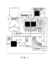
- FIG. 1 an electron microscope and a method for controlling its focus position according to the present invention will be schematically described.
- the electron microscope according to the present invention comprises: an electron optical system 2 for conducting electron beams to a sample 1; a focus control part 3 for controlling a focus position f of the electron optical system 2 with respect to the sample 1; an image detecting part 4 for detecting an image caused by electron beams aimed at the sample 1; a computer 5 for carrying out various operations and controls, and a stigmater 14 for correcting astigmatism.
- the computer 5 comprises a first operating means 11 for carrying out the Fourier transform (FFT) (spatial frequency transformation) of each of first and second images 7 and 8 detected by the image detecting part 4 at two focus positions, one of which is a suitably set first focus position f1 and the other of which is a second focus position f2 shifted from the first focus position f1 by a known focus shifted quantity ⁇ f, to obtain first and second transformed images 9 and 10 to mutually divide the first and second transformed images 9 and 10 on a spatial frequency plane (u, v) to derive a measured divided quantity Rexp indicative of the divided results as a function of a spatial frequency.
- FFT Fourier transform
- u and v denote spatial frequency variables of a rectangular coordinate system.
- the computer 5 has divided quantity data 12 which are previously prepared and stored as a function of a focus position and a spatial frequency as a set of theoretical divided quantities K(r;f)/K(r;f+ ⁇ f).
- the theoretical divided quantities K(r;f) /K(r;f+ ⁇ f) are obtained by deriving an image transfer function K (r, f) with respect to the electron optical system 2 as a function of a focus position and a spatial frequency, substituting the above described two focus positions, which are shifted by the focus shifted quantity ⁇ f, for the image transfer function K(r,f), obtaining a first transfer function value K(r;f) and a second transfer function value K(r;f+ ⁇ f), and mutually dividing the first transfer function value K(r;f1) and the second transfer function value K(r;f+ ⁇ f) on the spatial frequency plane (u,v).
- r denotes a spatial frequency variable of a polar coordinate system
- r 2 u 2 + v 2 .
- the computer 5 further comprises a secondoperatingmeans 13 for making a reference to the divided quantity data 12 to derive a theoretical divided quantity K(r;f0)/K(r;f0+ ⁇ f) wherein functional characteristics with respect to the spatial frequency correlate to the measured divided quantity Rexp, and for deriving a focus position f0 corresponding to the derived theoretical divided quantity (r;f0)/K(r;f0+ ⁇ f) as a first focus position f1.
- a secondoperatingmeans 13 for making a reference to the divided quantity data 12 to derive a theoretical divided quantity K(r;f0)/K(r;f0+ ⁇ f) wherein functional characteristics with respect to the spatial frequency correlate to the measured divided quantity Rexp, and for deriving a focus position f0 corresponding to the derived theoretical divided quantity (r;f0)/K(r;f0+ ⁇ f) as a first focus position f1.
- the focus control part 3 is capable of deriving the first focus position f1 as an absolute position by the results of operations carried out by the second operating means 13, the focus control part 13 is designed to control an electron lens 15 and so forth of the electron optical system 2 to focus the electron optical system 2 to obtain a clear formed image having an automatically adjusted focus.
- the present invention is intended to actually detect an electron optical state to use the detected results to automatically adjust the focus position and/or astigmatism, and is capable of automatically adjusting focusing regardless of the presence of astigmatism.
- the focusing in the absence of astigmatism, and the focusing in the presence of astigmatism (focusing with correction of astigmatism) will be described below.
- K(r;f+ ⁇ f) data are derived from K(r;f) data, so that the theoretical divided quantities K(r;f)/K(r;f+ ⁇ f) with respect to the focus position f can be theoretically easily calculated.
- the divided quantity data 12 is obtained as a set of theoretical divided quantities K(r;f)/K(r;f+ ⁇ f) with respect to various focus positions f.
- each of reference numbers 12a and 12b denotes a part of the divided quantity data 12.
- the axis of abscissas denotes focus positions (focus shifted quantities) f, and the axis of ordinates denotes spatial frequencies r.
- the divided quantity data 12 has been previously derived as a set of theoretical divided quantities K(r;f)/K(r;f+ ⁇ f) with respect to various focus positions f, and has been stored in a memory of the computer 5.
- ⁇ f is the same quantity as the focus shifted quantity ⁇ f which is used when a measured divided quantity Rexp is obtained. Since an effective spectral region increases if ⁇ f is not too wide and suitably set, ⁇ f may be set to be about 1 to 2 [Sch].
- the measured divided quantity Rexp will be described below.
- the first and second images 7 and 8 detected under different electron optical conditions are I 1 (x,y)7 and I 2 (x,y) 8, respectively.
- the transfer function K(u,v) with respect to the electron optical system 2 and the Fourier transforms F[I 1 (x,y)] 9 and F[I 2 (x,y)] 10 of the two images I 1 (x,y) and I 2 (x,y), and the Fourier transform F[O(x,y)] with respect to the sample function O(x,y) of the sample 1, the following expression is established.
- F[I 1.2 (x,y)] F[O(x,y)] ⁇ K 1.2 (u,v)
- the measured divided quantity Rexp obtained by carrying out division between the F[I 1 (x,y)] and F[I 2 (x,y)] does not include the sample function O(x,y) and is expressed by a ratio of the values of the transfer functions K(u,v) at the respective focus positions f1 and f2, as expressed by the following expression.
- the measured divided quantity Rexp is expressed by the expression defined only by the electron optical state of the electron optical system 2 without depending on characteristics of various spatial frequencies of various samples 1 themselves.
- two STEM images I 1 (x,y) 7 and I 2 (x,y) 8 are acquired by shifting the focus position by a predetermined focus shifted quantity ⁇ f.
- the step ST4 comprises a step ST4a of carrying out the transformation of coordinate system from (u,v) to (r, ⁇ ), a step ST4b of averaging one-dimensional data, and a step ST4c of carrying out a signal-noise separation.
- the operating step of carrying out focusing (correction of astigmatism) in the presence of astigmatism is more complicated than the operating step of carrying out focusing in the absence of astigmatism.
- Rexp (u,v) is transformed to Rexp (r, ⁇ ) in view of the rotation symmetry of the measured divided quantity Rexp (r, ⁇ ), and subsequently, all of radius vector distributions Rexp(r, ⁇ ) in discrete directions ⁇ i are averaged as shown by expression (3).
- N denotes the number of discrete directions ⁇ i
- the interval between adjacent discrete directions ⁇ i is, e.g., 1 [degree].
- the upper limit of the spatial frequency required to carry out the fitting of the Rave (r) to the divided quantity data 12 by the cross-correlation method is obtained as follows.
- binary images B (rj, ⁇ i) are prepared by an experimental threshold level to power spectra.
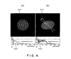
- a one-dimensional radius vector counting histogram P(rj) is prepared for them (see FIG. 4 (a-2)).
- this histogram is expressed as follows.
- the upper limit of the spatial frequency for coincidence of correlation is estimated by a computer program.
- the quantity of a lens current for moving the focus position to the Scherzer focus position is calculated on the basis of the focus position f obtained at ST6, and this is fed back to this lens system.
- the transfer function K(u,v) has not been a circular annular pattern, and has been an elliptical annular pattern or a radial pattern. If the pattern is an elliptical ring, the difference fa in astigmatism and the focus position f can be directly obtained by measuring characteristic positions on major and minor axes. The f1 can be obtained by measuring them on an intermediate axis between the major and minor axes. The value of the focus position on the minor axis corresponds to the maximum theoretical divided quantity, the value of the focus position on the major axis corresponds to the minimum theoretical divided quantity, and an average theoretical divided quantity corresponds to the focus position on the intermediate axis.
- the Rexp(u,v) is calculated, and at ST4a, the Rexp(u,v) is transformed to the (r, ⁇ ) coordinate system to be Rexp(r, ⁇ ). Subsequently, all sets of radius vector distributions Rexp (r, ⁇ ) are averaged in a narrow range of discrete direction ⁇ i-m ⁇ ⁇ i ⁇ ⁇ i+m, and the radius vector distribution in directions of ⁇ i is newly expressed by the respective averaged distributions as follows: wherein the number of additional angles from ⁇ +m to ⁇ -m is M. At this time, the additional angle
- is set to be 9 [deg].
- FIG. 4(b-1) shows a measured divided quantity Rexp in the presence of astigmatism
- FIG. 4 (b-2) shows a one-dimensional radius vector counting histogram P(rj) derived with respect to the discrete angular range
- the fitting operation is carried out by the cross-correlation.
- the fitting operation of the averaged one-dimensional Rave(r, ⁇ ) in all discrete orientations to K(r;f)/K(r;f+ ⁇ f) of the theoretical model may be carried out as shown in FIG. 3.
- Rave. (r, ⁇ i) with respect to each orientation ⁇ i is used for carrying out a cross-correlation operation every orientation.
- the focus shifted quantity having the maximum correlation coefficient every angle ⁇ i measured by the cross-correlation is obtained. It is assumed that this is F ( ⁇ i).
- the quantity of current to be adjusted with respect to each of x and y components in the correction of astigmatism by the stigmater 14 is calculated from the measured values of fa and ⁇ a to be fed back to carry out the astigmatism correction.
- FIGS. 7 through 10 The results obtained by repeating experiments by applying a method for controlling the focus position of an electron microscope according to the present invention are shown in FIGS. 7 through 10.
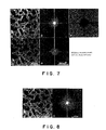
- FIG. 7 shows the results of automatic focusing experiments using a thin-film sample of a DRAM being a semiconductor device.
- two HAADF-STEM images dark-field scanning transmission electron microscope images by a high-angle annular-type detector
- FIGS. 7(a) and 7(d) show power spectra obtained by the Fourier transform of the images of FIGS. 7 (a) and 7(d).
- FIG. 7(c) shows the measured divided quantity Rexp(u,v) obtained by division.
- FIG. 8 (a) shows an image after automatic focusing
- FIG. 8 (b) shows power spectra obtainedby the Fourier transform of the image. Even if such a general sample was used, it was possible to confirm the operation with high reliability.
- FIG. 9 shows an experiment on automation of astigmatism correction.
- an Au particle deposited sample on a carbon thin film having a clear ring pattern as shown in FIGS. 2 (a) through 2 (h) was used in order to facilitate verification.
- the image acquiring conditions are the same as those in FIG. 7.
- FIGS. 9(b) and 9(e) show power spectra obtained by the Fourier transform of the images of FIGS. 9 (a) and 9(d).
- FIG. 9(c) shows the measured divided quantity Rexp (u,v) obtainedbydivision. It is observed that crossover lines shown in FIG.
- FIG. 10 (a) shows an image after automatic astigmatism correction
- FIG. 10(b) shows power spectra obtained by the Fourier transform of the image. It was found that very good astigmatism correction was carried out.
- the present invention should not be limited thereto, but the invention maybe applied to another physical quantity, e.g., an accelerating voltage of electron beams, if the physical quantity univocally influences the focal position of an electron microscope.
- the above described technical idea should not be limited thereto, but the idea may be applied to the control of the quantity of astigmatism.
- the same technique as that for detecting first and second two images at two focus positions, which are realized by changing a predetermined physical quantity by a known quantity, and comparing the detected results with theoretical data to recognize the electron optical state of the electron microscope to automatically adjust the focus position may be applied for detecting first and second two images by two astigmatism quantities, which are realized by changing a predetermined physical quantity by a known quantity, to compare the detected results with theoretical data to recognize the electron optical state of the electron microscope to automatically adjust the quantity of astigmatism.
Landscapes
- Chemical & Material Sciences (AREA)
- Analytical Chemistry (AREA)
- Automatic Focus Adjustment (AREA)
- Testing Or Measuring Of Semiconductors Or The Like (AREA)
Abstract
There are provided an electron microscope capable of
carrying out focusing and astigmatism correction without
depending on characteristics of a sample, and a method for
controlling its focus position.
The electron microscope according to the present
invention comprises: an electron optical system (2) ; a focus
control part (3) ; an image detectingpart (4) ; a first operating
part (11) for mutually dividing first and second transformed
images (9) and (10), which are obtained by carrying out the
fast Fourier transform of first and second images (7) and
(8) detected at two focus positions of a first focus position
(f1) and a second focus position (f2) shifted from the first
focus position by a known focus shifted quantity Δf, to obtain
a measured divided quantity Rexp; divided quantity data (12)
previously prepared and stored as a function of focus positions
and spatial frequencies as a set of theoretical divided
quantities, the theoretical divided quantities being obtained
by substituting the two focus positions shifted by the focus
shifted quantity Δf for an image transfer function (r,f) to
obtain first and second transfer function values K(r;f) and
(r;f+Δf) to mutually divide the first and second transfer
function values K(r;f1) and (r;f+Δf) on a spatial frequency
plane; and a second operating part (13) for making a reference
to the divided quantity data (12) to derive a theoretical
divided quantity K(r;f0) correlating to the measured divided
quantity Rexp, and for deriving a focus position f0
corresponding to the derived theoretical divided quantity
K(r;f0)/K(r;f0+Δf) as a first focus position f1.
Description
The present invention relates generally to an electron
microscope and a method for controlling the focus position
thereof. More specifically, the invention relates to an
electron microscope capable of automatically correcting its
focus position and astigmatism, and a method for controlling
the focus position.
In a case where the electron optical system of an electron
microscope is intended to be automatically adjusted, it is
not easy to carry out automation similar to the automatic
focusing function of general purpose optical cameras, video
cameras or the like. The main reasons for this include (1)
problems on S/N ratio and (2) aberration characteristics.
The S/N ratio of electron microscope images is lowunlike
general images, so that the processing of the differential
system of picture signals does not function. If an image having
a high S/N ratio is intended to be obtained, the dose of electron
beams must be increased. However, the irradiation damage of
a sample causes a problem, so that the adjusting method for
acquiring many images further increases this problem. In
addition, a high resolution must be achieved. Finally, even
if the S/N ratio is low, the processing of the differential
system of picture signals must function. This makes the
automatic adjusting method difficult.
The specific aberration characteristics of electron
microscopes also make the adjusting method difficult. In
general purpose optical cameras, only the focus maybe adjusted.
However, in the optical systems of electron microscopes,
astigmatism correction must be also adjusted in addition
thereto. Since there are two adjusting quantities (with
respect to x and y directions) in the adjustment of astigmatism
correction, the adjusting method is further complicated, so
that it is difficult to carry out the adjusting method. In
addition, unlike optical lens systems, spherical aberration
can not be corrected except for very special cases.
Particularly in high resolution electron microscopes, optimum
conditions can not be obtained on a so-called Gaussian plane.
This also makes the adjusting method difficult.
Thus, the electron optical system can not easily adj us ted,
so that it is desired to automate the adjustment of the electron
optical system.
In conventional three-dimensional electron microscopes,
it is required to acquire many images in order to automatically
adjust the electron optical system. Naturally, it is required
to obtain precise series images under the same optimum optical
conditions, so that there is a problem in that this is
complicated and is not easily achieved.
Moreover, when obtained electron microscope images are
utilized for carrying out focusing in conventional electron
microscopes, electron microscope images are naturally
reflected in characteristics of samples, such as compositions
and shapes, so that it is not possible to recognize electron
optical states from which characteristics of the samples are
abstracted. For that reason, there is a problem in that it
is not possible to precisely carry out focusing since the
degree of focusing depends on characteristics themselves of
the samples.
In addition, if astigmatism exists, it is required to
correct astigmatism by a so-called stigmater while it is not
possible to precisely carry out focusing.
It is therefore an object of the present invention to
eliminate the above described problems in the prior art and
to provide an electron microscope capable of simply, surely
and automatically adjusting electron optical parameters, such
as precise focusing and astigmatism correction, and a method
for controlling its focus position.
In order to accomplish the above described object,
according to one aspect of the present invention, an electron
microscope comprises: an electron optical system for
conducting an electron beam to a sample; a focus control part
for controlling a focus position of the electron optical system
with respect to the sample; an image detecting part for
detecting an image caused by the electron beam aimed at the
sample; first operating means for spatial frequency changing
each of first and second images, which are detected by the
image detecting part at two focus positions of a first focus
position and a second focus position which is a focus shifted
from the first focus position and which is realized by changing
a predetermined physical quantity by a known quantity, to
obtain first and second transformed images to mutually divide
the first and second transformed images on a spatial frequency
plane to derive a measured divided quantity indicative of
divided results as a function of a spatial frequency; divided
quantity data previously prepared as a function of focus
positions and spatial frequencies as a set of theoretical
divided quantities, the theoretical divided quantities being
obtained by deriving an image transfer function with respect
to the electron optical system as a function of focus positions
and spatial frequencies, substituting the two physical
quantities, which are shifted from each other by the known
quantity, for the image transfer function to obtain first
and second transfer function values to mutually divide the
first and second transfer function values on a spatial
frequency plane; and second operating means for making a
reference to the divided quantity data to derive the
theoretical divided quantities, wherein functional
characteristics with respect to a spatial frequency correlate
to the measured divided quantity, and for deriving a focus
position corresponding to the derived theoretical divided
quantity as the first focus position, wherein the focus
position of the electron optical system is controlled by the
focus control part on the basis of the operated results of
the second operating means.
The predetermined physical quantity may be a focus
position, and the known quantitymaybe a focus shiftedquantity
between the first and second focus positions.
The first operating means may average the divided results
to derive the measured divided quantity as a function of a
one-dimensional spatial frequency.
The first operating means may divide the divided results
into sections of a range of values of spatial frequencies
to average them every one of the sections to derive the measured
divided value as a one-dimensional spatial frequency every
one of the sections, and the second operating means may make
a reference to the divided quantity data to derive the
theoretical divided quantity, in which functional
characteristics with respect to a spatial frequency correlate
to the measured divided quantity, every one of the sections
to derive an average theoretical divided quantity of maximum
and minimum theoretical divided quantities of the theoretical
divided quantities derived every one of the sections, to derive
a focus position corresponding to the average theoretical
divided quantity as the first focus position. The electron
microscope may further comprise a stigmater for correcting
astigmatism, and astigmatism may be corrected by the
stigmater.
According to another aspect of the present invention,
an electron microscope comprises: an electron optical system
for conducting an electron beam to a sample; an astigmatism
control part for controlling astigmatism of the electron
optical system with respect to the sample; an image detecting
part for detecting an image caused by the electron beam aimed
at the sample; first operating means for spatial frequency
changing each of first and second images, which are detected
by the image detecting part at two astigmatism quantity of
a first astigmatism quantity and a second astigmatism quantity
which is an astigmatism quantity shifted from the first
astigmatism quantity and which is realized by changing a
predetermined physical quantity by a known quantity, to obtain
first and second transformed images to mutually divide the
first and second transformed images on a spatial frequency
plane to derive a measured divided quantity indicative of
divided results as a function of a spatial frequency; divided
quantity data previously prepared as a function of astigmatism
quantities and spatial frequencies as a set of theoretical
divided quantities, the theoretical divided quantities being
obtained by deriving an image transfer function with respect
to the electron optical system as a function of astigmatism
quantities and spatial frequencies, substituting the two
physical quantities, which are shifted from each other by
the known quantity, for the image transfer function to obtain
first and second transfer function values to mutually divide
the first and second transfer function values on a spatial
frequency plane; and second operating means for making a
reference to the divided quantity data to derive the
theoretical divided quantities, wherein functional
characteristics with respect to a spatial frequency correlate
to the measured divided quantity, and for deriving an
astigmatism quantity corresponding to the derived theoretical
divided quantity as the first astigmatism quantity, wherein
the astigmatism quantity of the electron optical system is
controlled by the astigmatism control part on the basis of
the operated results of the second operating means.
According to a further aspect of the present invention,
there is provided a method for controlling a focus position
of an electron microscope, the method comprising: a step of
conducting an electron beam to a sample; a first operating
step of spatial frequency changing each of first and second
images, which are detected by an image detecting part at two
focus positions of a first focus position and a second focus
position, which is a focus shifted from the first focus position
and which is realized by changing a predetermined physical
quantity by a known quantity, to obtain first and second
transformed images to mutually divide the first and second
transformed images on a spatial frequency plane to derive
a measured divided quantity indicative of divided results
as a function of a spatial frequency, when an image caused
by the electron beam aimed at the sample is detected by the
image detecting part; a second operating step of deriving
an image transfer function with respect to the electron optical
systemas a function of a focusposition anda spatial frequency,
to substitute the two physical quantities, which are shifted
from each other by the known quantity, for the image transfer
function to obtain first and second transfer function values
to mutually divide the first and second transfer function
values on a spatial frequency plane, to obtain theoretical
divided quantities to make a reference to divided quantity
data, which are previously prepared as a function of a focus
position and a spatial frequency as a set of the theoretical
divided quantities, to derive a focus position corresponding
to the derived theoretical divided quantities as the first
focus position; and a step of controlling the focus position
of the electron optical system by a focus control part, which
is provided for controlling the focus position of the electron
optical system with respect to the sample, on the basis of
the results of operation at the second operating step.
In the method for controlling a focus position of an
electron microscope, the predetermined physical quantity may
be a focus position, and the known quantity may be a focus
shifted quantitybetween the first and second focus positions.
The first operating means may average the divided results
to derive the measured divided quantity as a function of a
one-dimensional spatial frequency.
The first operating means may divide the divided resul ts
into sections of a range of values of spatial frequencies
to average them every one of the sections to derive the measured
divided value as a one-dimensional spatial frequency every
one of the sections, and the second operating means may make
a reference to the divided quantity data to derive the
theoretical divided quantity, in which functional
characteristics with respect to a spatial frequency correlate
to the measured divided quantity, every one of the sections
to derive an average theoretical divided quantity of maximum
and minimum theoretical divided quantities of the theoretical
divided quantities derived every one of the sections, to derive
a focus position corresponding to the average theoretical
divided quantity as the first focus position. The astigmatism
may be corrected by a stigmater.
According to a still further aspect of the present
invention, there is provided a method for controlling an
astigmatism quantity of an electron microscope, the method
comprising: a step of conducting an electron beam to a sample;
a first operating step of spatial-frequency-changing each
of first and second images, which are detected by an image
detecting part at two astigmatism quantities of a first
astigmatism quanti ty and a second astigmatism quanti ty, which
is an astigmatism quantity shifted from the first astigmatism
quantity and which is realized by changing a predetermined
physical quantity by a known quantity, to obtain first and
second transformed images to mutually divide the first and
second transformed images on a spatial frequency plane to
derive a measured divided quantity indicative of divided
results as a function of a spatial frequency, when an image
caused by the electron beam aimed at the sample is detected
by the image detecting part; a second operating step of deriving
an image transfer function with respect to the electron optical
system as a function of an astigmatism quantity and a spatial
frequency, to substitute the two physical quantities, which
are shifted from each other by the known quantity, for the
image transfer function to obtain first and second transfer
function values to mutually divide the first and second
transfer function values on a spatial frequency plane, to
obtain theoretical divided quantities to make a reference
to divided quantity data, which are previously prepared as
a function of an astigmatism quantity and a spatial frequency
as a set of the theoretical divided quantities, to derive
an astigmatism quantity corresponding to the derived
theoretical divided quantities as the first astigmatism
quantity; and a step of controlling the astigmatism quantity
of the electron optical system by a focus control part, which
is provided for controlling the astigmatism quantity of the
electron optical system with respect to the sample, on the
basis of the results of operation at the second operating
step.
In the above described invention, the first and second
two images are detected at two focus positions, which are
realized by changing the physical quantity, such as a focus
position, to compare the detected results with theoretical
data to recognize the electron optical state of the electron
microscope to automatically adjust the focus position and/or
focusing in the presence of astigmatism. Each of the first
and second images obtained at the first and second two focus
positions is spatial frequency changed to obtain first
transformed images to mutually divide the first and second
transformed images on the spatial frequency plane, so that
it is possible to eliminate the sample function O(x,y)
depending the kind of the sample. The measured divided
quantity is expressed by information on only the electron
optical state of the electron optical system without depending
on characteristics of various spatial frequencies of the
samples themselves, which are capable of being possessed by
various samples. As a result, it is possible to precisely
carry out focusing and astigmatism correction without
depending on characteristics of samples.
The same technique as that for detecting the first and
second two images at two focus positions, which are realized
by changing the predetermined physical quantity by the known
quantity, to compare the detected results with theoretical
data to recognize the electron optical state of the electron
microscope to automatically adjust the focus position can
be applied for detecting first and second two images at two
astigmatism quantities, which are realized by changing a
predetermined physical quantity by a known quantity, to
compare the detected results with theoretical data to
recognize the electron optical state of the electron
microscope to automatically astigmatism quantity.
Referring to the accompanying drawings, the preferred
embodiment of an electron microscope and a method for
controlling its focus position according to the present
invention will be described below.
The present invention is intended to detect first and
second two images at two focus positions, which are realized
by changing a predetermined physical quantity only by a known
quantity, to compare the detected results with theoretical
data to recognize the electron optical state of an electron
microscope to automatically adjust its focus position and/or
astigmatism. The predetermined physical quantity may be any
physical quantity univocally influencing the focus position
of the electron microscope. The predetermined physical
quantity should not be limited to the focus position, but
it may be another physical quantity, e.g., an accelerating
voltage of electron beams. In the following descriptions,
the focus position itself will be used as an example of a
predetermined physical quantity capable of being easily
handled, and a focus shifted quantity between two focus
positions is used as the known quantity.
First, referring to FIG. 1, an electron microscope and
a method for controlling its focus position according to the
present invention will be schematically described.
As shown in FIG. 1, the electron microscope according
to the present invention comprises: an electron optical system
2 for conducting electron beams to a sample 1; a focus control
part 3 for controlling a focus position f of the electron
optical system 2 with respect to the sample 1; an image detecting
part 4 for detecting an image caused by electron beams aimed
at the sample 1; a computer 5 for carrying out various operations
and controls, and a stigmater 14 for correcting astigmatism.
The computer 5 comprises a first operating means 11 for
carrying out the Fourier transform (FFT) (spatial frequency
transformation) of each of first and second images 7 and 8
detected by the image detecting part 4 at two focus positions,
one of which is a suitably set first focus position f1 and
the other of which is a second focus position f2 shifted from
the first focus position f1 by a known focus shifted quantity
Δf, to obtain first and second transformed images 9 and 10
to mutually divide the first and second transformed images
9 and 10 on a spatial frequency plane (u, v) to derive a measured
divided quantity Rexp indicative of the divided results as
a function of a spatial frequency. Herein, u and v denote
spatial frequency variables of a rectangular coordinate
system.
The computer 5 has divided quantity data 12 which are
previously prepared and stored as a function of a focus position
and a spatial frequency as a set of theoretical divided
quantities K(r;f)/K(r;f+Δf). The theoretical divided
quantities K(r;f) /K(r;f+Δf) are obtained by deriving an image
transfer function K (r, f) with respect to the electron optical
system 2 as a function of a focus position and a spatial
frequency, substituting the above described two focus
positions, which are shifted by the focus shifted quantity
Δf, for the image transfer function K(r,f), obtaining a first
transfer function value K(r;f) and a second transfer function
value K(r;f+Δf), and mutually dividing the first transfer
function value K(r;f1) and the second transfer function value
K(r;f+Δf) on the spatial frequency plane (u,v). Herein, r
denotes a spatial frequency variable of a polar coordinate
system, and r2 = u2 + v2.
The computer 5 further comprises a secondoperatingmeans
13 for making a reference to the divided quantity data 12
to derive a theoretical divided quantity K(r;f0)/K(r;f0+Δf)
wherein functional characteristics with respect to the spatial
frequency correlate to the measured divided quantity Rexp,
and for deriving a focus position f0 corresponding to the
derived theoretical divided quantity (r;f0)/K(r;f0+Δf) as
a first focus position f1.
Since the focus control part 3 is capable of deriving
the first focus position f1 as an absolute position by the
results of operations carried out by the second operating
means 13, the focus control part 13 is designed to control
an electron lens 15 and so forth of the electron optical system
2 to focus the electron optical system 2 to obtain a clear
formed image having an automatically adjusted focus.
The details of the above described contents will be
described below.
The present invention is intended to actually detect
an electron optical state to use the detected results to
automatically adjust the focus position and/or astigmatism,
and is capable of automatically adjusting focusing regardless
of the presence of astigmatism. The focusing in the absence
of astigmatism, and the focusing in the presence of astigmatism
(focusing with correction of astigmatism) will be described
below.
First, referring to FIG. 2, the divided quantity data
12 will be described below.
The transfer function K (u, v) wi th respect to the electron
optical system 2 can be theoretically obtained from the
geometry of the electron optical system 2. If the electron
optical system 2 has a rotation symmetry, K(u,v;f) can be
indicated as K(r;f). In FIG. 2, (a), (b), ..., (h) denoteK(r;f)
at various focus positions f. Since the electron optical
system 2 is axis-symmetric, K(r;f) is indicated as a
ring-shaped pattern. Herein, r2 = u2 + v2.
If Δf has been determined, K(r;f+Δf) data are derived
from K(r;f) data, so that the theoretical divided quantities
K(r;f)/K(r;f+Δf) with respect to the focus position f can
be theoretically easily calculated. The divided quantity
data 12 is obtained as a set of theoretical divided quantities
K(r;f)/K(r;f+Δf) with respect to various focus positions f.
In FIG. 2, each of reference numbers 12a and 12b denotes a
part of the divided quantity data 12. The axis of abscissas
denotes focus positions (focus shifted quantities) f, and
the axis of ordinates denotes spatial frequencies r. The
divided quantity data 12 has been previously derived as a
set of theoretical divided quantities K(r;f)/K(r;f+Δf) with
respect to various focus positions f, and has been stored
in a memory of the computer 5. Herein, Δf is the same quantity
as the focus shifted quantity Δf which is used when a measured
divided quantity Rexp is obtained. Since an effective
spectral region increases if Δf is not too wide and suitably
set, Δf may be set to be about 1 to 2 [Sch].
The measured divided quantity Rexp will be described
below.
It is assumed that the first and second images 7 and
8 detected under different electron optical conditions
(different focus shifted quantities) are I1(x,y)7 and I2(x,y) 8,
respectively. Between the transfer function K(u,v) with
respect to the electron optical system 2, and the Fourier
transforms F[I1(x,y)] 9 and F[I2(x,y)] 10 of the two images
I1(x,y) and I2(x,y), and the Fourier transform F[O(x,y)] with
respect to the sample function O(x,y) of the sample 1, the
following expression is established.
F[I1.2 (x,y)] = F[O(x,y)] · K1.2 (u,v)
It should be noted that the measured divided quantity
Rexp obtained by carrying out division between the F[I1(x,y)]
and F[I2(x,y)] does not include the sample function O(x,y)
and is expressed by a ratio of the values of the transfer
functions K(u,v) at the respective focus positions f1 and
f2, as expressed by the following expression.

As a result, the measured divided quantity Rexp is
expressed by the expression defined only by the electron
optical state of the electron optical system 2 without
depending on characteristics of various spatial frequencies
of various samples 1 themselves.
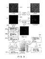
Referring to FIGS. 3 through 6, the processing procedure
for carrying out the adjustment of astigmatism fa, orientation
ϕa of astigmatism, and the focus position (focus shifted
quantity) f will be described below. Herein, focusing is
carried out by the focus control part 3, and usual astigmatism
correction is carried out by the stigmater 14 for correcting
astigmatism. Although it does not matter whether the focusing
operation by the focus control part 3 or the astigmatism
correcting operation by the stigmater 14 is formerly carried
out, a case where the focusing operation is formerly carried
out will be described below.
First, at ST1, two STEM images I1(x,y) 7 and I2(x,y)
8 are acquired by shifting the focus position by a predetermined
focus shifted quantity Δf.
Then, at ST2, the Fourier transform of the acquired image
is carried out for obtaining F[I1(x,y)] 9 and F[I2(x,y)] 10.
Then, at ST3, division on the spatial frequency plane
(u,v) is carried out for obtaining F[I1(x,y)]/F[I2(x,y)] (=
measured divided quantity Rexp(u,v)).
Then, at ST4, the data processing of the measured divided
quantity Rexp(u,v) is carried out.
The step ST4 comprises a step ST4a of carrying out the
transformation of coordinate system from (u,v) to (r, ), a
step ST4b of averaging one-dimensional data, and a step ST4c
of carrying out a signal-noise separation.
In the data processing at ST4, the operating step of
carrying out focusing (correction of astigmatism) in the
presence of astigmatism is more complicated than the operating
step of carrying out focusing in the absence of astigmatism.
Therefore, in order to facilitate better understanding,
the focusing in the absence of astigmatism will be first
described.
In the absence of astigmatism, Rexp (u,v) is transformed
to Rexp (r, ) in view of the rotation symmetry of the measured
divided quantity Rexp (r, ), and subsequently, all of radius
vector distributions Rexp(r, ) in discrete directions i
are averaged as shown by expression (3).

As one-dimensional data, Rave(r) is obtained. Herein,
N denotes the number of discrete directions i, and the
interval between adjacent discrete directions i is, e.g.,
1 [degree].
Then, at the step ST4 of carrying out the signal-noise
separation, the upper limit of the spatial frequency required
to carry out the fitting of the Rave (r) to the divided quantity
data 12 by the cross-correlation method is obtained as follows.
First, binary images B (rj, i) are prepared by an experimental
threshold level to power spectra. In addition, a
one-dimensional radius vector counting histogram P(rj) is
prepared for them (see FIG. 4 (a-2)). Using a higher relative
point number than the threshold as a function of a spatial
frequency radius (r), this histogram is expressed as follows.

From this histogram, the upper limit of the spatial
frequency for coincidence of correlation is estimated by a
computer program.
Then, at ST5, the fitting of Rave(r) derived from
expression (3) to the divided quantity data 12 is carried
outbythecross-correlationmethod. Then, atST6, themaximum
cross-correlation coefficient (XCCmax) is searched. Thus,
the best coincident value of the focus position f1 can be
obtained (see FIGS. 5(a) and 5(b)).
Then, at ST7, the quantity of a lens current for moving
the focus position to the Scherzer focus position is calculated
on the basis of the focus position f obtained at ST6, and
this is fed back to this lens system. By the above described
steps, the focusing in the absence of astigmatism can be
precisely carried out regardless of characteristics of the
sample 1.
The automatic focusing in the presence of astigmatism
(aberration correction) will be described below.
The transfer function K(u,v) has not been a circular
annular pattern, and has been an elliptical annular pattern
or a radial pattern. If the pattern is an elliptical ring,
the difference fa in astigmatism and the focus position f
can be directly obtained by measuring characteristic positions
on major and minor axes. The f1 can be obtained by measuring
them on an intermediate axis between the major and minor axes.
The value of the focus position on the minor axis corresponds
to the maximum theoretical divided quantity, the value of
the focus position on the major axis corresponds to the minimum
theoretical divided quantity, and an average theoretical
divided quantity corresponds to the focus position on the
intermediate axis.
In the case, the data processing at ST4 is carried out
as follows.
The Rexp(u,v) is calculated, and at ST4a, the Rexp(u,v)
is transformed to the (r, ) coordinate system to be Rexp(r,
). Subsequently, all sets of radius vector distributions
Rexp (r, ) are averaged in a narrow range of discrete direction
i-m < i < i+m, and the radius vector distribution in
directions of i is newly expressed by the respective averaged
distributions as follows:
 wherein the number of additional angles from +m to -m is
M. At this time, the additional angle |±m| is set to be 9
[deg].
wherein the number of additional angles from +m to -m is
M. At this time, the additional angle |±m| is set to be 9
[deg].
A processing for generating discrete data every angle
to separate noise regions is carried out. Since S/N changes
every angle, the noise regions must be separated every angle.
The separation of signal regions from noise regions is carried
out by a simple threshold processing of intensity level of
power spectra in the same manner as that in the above described
expression (4). The fitting operation by correlation is
carried out in the signal region determined by the separation.
FIG. 4(b-1) shows a measured divided quantity Rexp in the
presence of astigmatism, and FIG. 4 (b-2) shows a
one-dimensional radius vector counting histogram P(rj)
derived with respect to the discrete angular range |±m| in
FIG. 4 (b-1), for obtaining the upper limit of spatial frequency,
which is required to carry out the fitting of Rave (r) to the
divided quantity data by the cross-correlation method, every
discrete angular range |±m|.
Then, the fitting operation is carried out by the
cross-correlation. When focusing is carried out in the case
of only focus shift correction, i.e., in the absence of
astigmatism, the fitting operation of the averaged
one-dimensional Rave(r, ) in all discrete orientations to
K(r;f)/K(r;f+Δf) of the theoretical model may be carried out
as shown in FIG. 3. On the other hand, in the presence of
astigmatism, Rave. (r, i) with respect to each orientation
i is used for carrying out a cross-correlation operation every
orientation. Thus, the focus shifted quantity having the
maximum correlation coefficient every angle i measured by
the cross-correlation is obtained. It is assumed that this
is F (i). Then, fa, ϕa and f are measured. In order to enhance
reliability, approximation is carried out by the method of
least squares. Since F(i) depends on double symmetric
astigmatism, it can be approximated to the expression
[f- (fa/2) cos (2-ϕa)]. Therefore, the following equation can
be derived.

In this equation, it is not simply possible to
mathematically solve the angle ϕa of astigmatism. However,
it can be solved by the numerical calculation since ϕa exists
in the effective range of from 0 to π. If ϕa is fixed, f and
fa can be simply obtained by
∂S ∂f = 0 and ∂S ∂(fa /2) =0
as follows:
f = DB - AC NB-A 2 ;
fa = 2(AD -NC ) NB-A 2 ;



 wherein N is the number of data of angle i. Moreover, if
i are given equally at regular intervals from 0 to π (at an
interval of 1 [deg] at this time), A = 0, and f and fa are
expressed by the following simpler expressions.
wherein N is the number of data of angle i. Moreover, if
i are given equally at regular intervals from 0 to π (at an
interval of 1 [deg] at this time), A = 0, and f and fa are
expressed by the following simpler expressions.
F = D/N; fa = -2C/B
By using the above values as f and fa and comparing all of
the calculated errors S of least squares while changing ϕa
at fine intervals from 0 to π, ϕa is obtained. The ϕa having
the minimum error S is the answer. Thus, f, fa and ϕa are
measured.
Then, the quantity of current to be adjusted with respect
to each of x and y components in the correction of astigmatism
by the stigmater 14 is calculated from the measured values
of fa and ϕa to be fed back to carry out the astigmatism
correction.
If necessary, the above described process is repeated
several times.
Finally, the final focus correction is fed back so that
the corrected focus is the Scherzer focus.
Thus, according to this preferred embodiment, it is
possible to carry out focusing regardless of characteristics
of the sample 1, so that it is possible to obtain an image
wherein astigmatism has been precisely corrected.
Referring to FIGS. 7 through 10, the results of
experiments using a practical apparatus will be described
below.
The results obtained by repeating experiments by
applying a method for controlling the focus position of an
electron microscope according to the present invention are
shown in FIGS. 7 through 10.
FIG. 7 shows the results of automatic focusing
experiments using a thin-film sample of a DRAM being a
semiconductor device. First, two HAADF-STEM images
(dark-field scanning transmission electron microscope images
by a high-angle annular-type detector) were acquired (direct
magnification x60000, 1 [pixel] = 5/3 [nm]) (FIGS. 7(a) and
7(d)). Herein, after the first image (FIG. 7 (a)) was acquired,
the focus was changed by Δf (Δf = 1.82 [Sch]) to acquire the
second image (FIG. 7 (b)), and the automatic adjusting method
was applied thereto. FIGS. 7 (b) and 7 (e) show power spectra
obtained by the Fourier transform of the images of FIGS. 7 (a)
and 7(d). FIG. 7(c) shows the measured divided quantity
Rexp(u,v) obtained by division.
FIG. 8 (a) shows an image after automatic focusing, and
FIG. 8 (b) shows power spectra obtainedby the Fourier transform
of the image. Even if such a general sample was used, it was
possible to confirm the operation with high reliability.
FIG. 9 shows an experiment on automation of astigmatism
correction. In this experiment, an Au particle deposited
sample on a carbon thin film having a clear ring pattern as
shown in FIGS. 2 (a) through 2 (h) was used in order to facilitate
verification. The image acquiring conditions are the same
as those in FIG. 7. After the first image (FIG. 9(a) was
acquired, the focus was changed by Δf to acquire the second
image (FIG. 9(b)). FIGS. 9(b) and 9(e) show power spectra
obtained by the Fourier transform of the images of FIGS. 9 (a)
and 9(d). FIG. 9(c) shows the measured divided quantity
Rexp (u,v) obtainedbydivision. It is observed that crossover
lines shown in FIG. 9(c) are coincident with the major and
minor axes of an ellipse very well. After the results of the
experiment, it was found from the results of calculation that
the focus shifted quantity f = 5.89 [Sch], astigmatism fa
= 2.58 [Sch] and the angle ψa = 155 [deg].
FIG. 10 (a) shows an image after automatic astigmatism
correction, and FIG. 10(b) shows power spectra obtained by
the Fourier transform of the image. It was found that very
good astigmatism correction was carried out.
After the results of the experiments using the practical
apparatus, it was validated that the automatic adjusting
system can be operated with high reliability in a processing
time of several seconds.
From approximating calculations based on the phase
contrast transfer function (PCTF) of the transmission electron
microscope image (TEM), the following expected precision
(Δferror) was calculated and evaluated. It was found that
the precision can approach 1 nm.
| Defocusf [Sch] | |Δferror| [Sch] ( |Δferror| [nm]) |
| 2 | -0.025(-1.4) |
| 5 | -0.11(-6.5) |
| 15 | -0.38(-22) |
While the scanning transmission electron microscope
(STEM) has been described as an example in the above described
preferred embodiment, the present invention should not be
limited thereto, but the invention maybe applied to a scanning
electron microscope or a transmission electron microscope.
While the focus position has been used as an example
of a predetermined physical quantity, the present invention
should not be limited thereto, but the invention maybe applied
to another physical quantity, e.g., an accelerating voltage
of electron beams, if the physical quantity univocally
influences the focal position of an electron microscope.
While the focusing of the electron microscope has been
described, the above described technical idea should not be
limited thereto, but the idea may be applied to the control
of the quantity of astigmatism. In this case, the same
technique as that for detecting first and second two images
at two focus positions, which are realized by changing a
predetermined physical quantity by a known quantity, and
comparing the detected results with theoretical data to
recognize the electron optical state of the electron
microscope to automatically adjust the focus position may
be applied for detecting first and second two images by two
astigmatism quantities, which are realized by changing a
predetermined physical quantity by a known quantity, to
compare the detected results with theoretical data to
recognize the electron optical state of the electron
microscope to automatically adjust the quantity of
astigmatism.
As described above, according to the present invention,
it is possible to carry out focusing regardless of the presence
of astigmatism without depending on characteristics of the
sample, and it is also possible to correct astigmatism.
Claims (12)
- An electron microscope comprising:wherein the focus position of said electron optical system is controlled by said focus control part on the basis of the operated results of said second operating means.an electron optical system for conducting an electron beam to a sample;a focus control part for controlling a focus position of said electron optical system with respect to said sample;an image detecting part for detecting an image caused by said electron beam aimed at said sample;first operating means for spatial frequency changing each of first and second images, which are detected by said image detecting part at two focus positions of a first focus position and a second focus position which is a focus shifted from said first focus position and which is realized by changing a predetermined physical quantity by a known quantity, to obtain first and second transformed images to mutually divide said first and second transformed images on a spatial frequency plane to derive a measured divided quantity indicative of divided results as a function of a spatial frequency;divided quantity data previously prepared as a function of focus positions and spatial frequencies as a set of theoretical divided quantities, said theoretical divided quantities being obtained by deriving an image transfer function with respect to said electron optical system as a function of focus positions and spatial frequencies, substituting said two physical quantities, which are shifted from each other by said known quantity, for said image transfer function to obtain first and second transfer function values to mutually divide said first and second transfer function values on a spatial frequency plane; andsecond operating means for making a reference to said divided quantity data to derive said theoretical divided quantities, wherein functional characteristics with respect to a spatial frequency correlate to said measured divided quantity, and for deriving a focus position corresponding to the derived theoretical divided quantity as said first focus position,
- An electron microscope as set forth in claim 1, wherein said predetermined physical quantity is a focus position, and said known quantity is a focus shifted quantity between said first and second focus positions.
- An electron microscope as set forth in claim 1, wherein said first operating means averages said divided results to derive said measured divided quantity as a function of a one-dimensional spatial frequency.
- An electron microscope as set forth in claim 1, wherein said first operating means divides said divided results into sections of a range of values of spatial frequencies to average them every one of said sections to derive said measured divided value as a one-dimensional spatial frequency every one of said sections, and
said second operating means makes a reference to said divided quantity data to derive said theoretical divided quantity, in which functional characteristics with respect to a spatial frequency correlate to said measured divided quantity, every one of said sections to derive an average theoretical divided quantity of maximum and minimum theoretical divided quantities of the theoretical divided quantities derived every one of said sections, to derive a focus position corresponding to said average theoretical divided quantity as said first focus position. - An electron microscope as set forth in claim 4, which further comprises a stigmater for correcting astigmatism, and wherein astigmatism is corrected by said stigmater.
- An electron microscope comprising:wherein the astigmatism quantity of said electron optical system is controlled by said astigmatism control part on the basis of the operated results of said second operating means.an electron optical system for conducting an electron beam to a sample;an astigmatism control part for controlling astigmatism of said electron optical system with respect to said sample;an image detecting part for detecting an image caused by said electron beam aimed at said sample;first operating means for spatial frequency changing each of first and second images, which are detected by said image detecting part at two astigmatism quantity of a first astigmatism quantity and a second astigmatism quantity which is an astigmatism quantity shifted from said first astigmatism quantity and which is realized by changing a predetermined physical quantity by a known quantity, to obtain first and second transformed images to mutually divide said first and second transformed images on a spatial frequency plane to derive a measured divided quantity indicative of divided results as a function of a spatial frequency;divided quantity data previously prepared as a function of astigmatism quantities and spatial frequencies as a set of theoretical divided quantities, said theoretical divided quantities being obtained by deriving an image transfer function with respect to said electron optical system as a function of astigmatism quantities and spatial frequencies, substituting said two physical quantities, which are shifted from each other by said known quantity, for said image transfer function to obtain first and second transfer function values to mutually divide said first and second transfer function values on a spatial frequency plane; andsecond operating means for making a reference to said divided quantity data to derive said theoretical divided quantities, wherein functional characteristics with respect to a spatial frequency correlate to said measured divided quantity, and for deriving an astigmatism quantity corresponding to the derived theoretical divided quantity as said first astigmatism quantity,
- Amethod for controlling a focus position of an electron microscope, said method comprising:a step of conducting an electron beam to a sample;a first operating step of spatial frequency changing each of first and second images, which are detected by an image detecting part at two focus positions of a first focus position and a second focus position, which is a focus shifted from said first focus position and which is reali zedby changing a predetermined physical quantity by a known quantity, to obtain first and second transformed images to mutually divide said first and second transformed images on a spatial frequency plane to derive a measured divided quantity indicative of divided results as a function of a spatial frequency, when an image caused by said electron beam aimed at said sample is detected by said image detecting part;a second operating step of deriving an image transfer function with respect to said electron optical system as a function of a focus position and a spatial frequency, to substitute said two physical quantities, which are shifted from each other by said known quantity, for said image transfer function to obtain first and second transfer function values to mutually divide said first and second transfer function values on a spatial frequency plane, to obtain theoretical divided quantities to make a reference to divided quantity data, which are previously prepared as a function of a focus position and a spatial frequency as a set of said theoretical divided quantities, to derive a focus position corresponding to the derived theoretical divided quantities as said first focus position; anda step of controlling the focus position of said electron optical system by a focus control part, which is provided for controlling the focus position of said electron optical system with respect to said sample, on the basis of the results of operation at said second operating step.
- Amethod for controlling a focus position of an electron microscope as set forth in claim 7, wherein said predetermined physical quantity is a focus position, and said known quantity is a focus shifted quantity between said first and second focus positions.
- Amethod for controlling a focus position of an electron microscope as set forth in claim 7, wherein said first operating means averages said divided results to derive said measured divided quantity as a function of a one-dimensional spatial frequency.
- Amethod for controlling a focus position of an electron microscope as set forth in claim 7, wherein said first operating means divides said divided results into sections of a range of values of spatial frequencies to average them every one of said sections to derive said measured divided value as a one-dimensional spatial frequency every one of said sections, and
said second operating means makes a reference to said divided quantity data to derive said theoretical divided quantity, in which functional characteristics with respect to a spatial frequency correlate to said measured divided quantity, every one of said sections to derive an average theoretical divided quantity of maximum and minimum theoretical divided quantities of the theoretical divided quantities derived every one of said sections, to derive a focus position corresponding to said average theoretical divided quantity as said first focus position. - Amethod for controlling a focus position of an electron microscope as set forth in claim 7, wherein astigmatism is corrected by a stigmater.
- A method for controlling an astigmatism quantity of an electron microscope, said method comprising:a step of conducting an electron beam to a sample;a first operating step of spatial-frequency-changing each of first and second images, which are detected by an image detecting part at two astigmatism quantities of a first astigmatism quantity and a second astigmatism quantity, which is an astigmatism quantity shifted from said first astigmatism quantity and which is realized by changing a predetermined physical quantity by a known quantity, to obtain first and second transformed images to mutually divide said first and second transformed images on a spatial frequency plane to derive a measured divided quantity indicative of divided results as a function of a spatial frequency, when an image caused by said electron beam aimed at said sample is detected by said image detecting part;a second operating step of deriving an image transfer function with respect to said electron optical system as a function of an astigmatism quantity and a spatial frequency, to substitute said two physical quantities, which are shifted from each other by said known quantity, for said image transfer function to obtain first and second transfer function values to mutually divide said first and second transfer function values on a spatial frequency plane, to obtain theoretical divided quantities to make a reference to divided quantity data, which are previously prepared as a function of an astigmatism quantity and a spatial frequency as a set of said theoretical divided quantities, to derive an astigmatism quantity corresponding to the derived theoretical divided quantities as said first astigmatism quantity; anda step of controlling the astigmatism quantity of said electron optical system by a focus control part, which is provided for controlling the astigmatism quantity of said electron optical system with respect to said sample, on the basis of the results of operation at said second operating step.
Applications Claiming Priority (3)
| Application Number | Priority Date | Filing Date | Title |
|---|---|---|---|
| JP2001182060A JP3645198B2 (en) | 2001-06-15 | 2001-06-15 | Electron microscope and focus position control method thereof |
| JP2001182060 | 2001-06-15 | ||
| PCT/JP2002/005749 WO2002103744A1 (en) | 2001-06-15 | 2002-06-10 | Electron microscope and its focal point control method |
Publications (2)
| Publication Number | Publication Date |
|---|---|
| EP1396872A1 true EP1396872A1 (en) | 2004-03-10 |
| EP1396872A4 EP1396872A4 (en) | 2005-01-19 |
Family
ID=19022226
Family Applications (1)
| Application Number | Title | Priority Date | Filing Date |
|---|---|---|---|
| EP02736041A Withdrawn EP1396872A4 (en) | 2001-06-15 | 2002-06-10 | ELECTRONIC MICROSCOPE AND METHOD OF ADJUSTING ITS FOCAL POINT |
Country Status (4)
| Country | Link |
|---|---|
| US (1) | US6984823B2 (en) |
| EP (1) | EP1396872A4 (en) |
| JP (1) | JP3645198B2 (en) |
| WO (1) | WO2002103744A1 (en) |
Cited By (1)
| Publication number | Priority date | Publication date | Assignee | Title |
|---|---|---|---|---|
| EP2058835A1 (en) * | 2007-11-12 | 2009-05-13 | FEI Company | Autofocussing method |
Families Citing this family (10)
| Publication number | Priority date | Publication date | Assignee | Title |
|---|---|---|---|---|
| JP4275441B2 (en) | 2003-03-31 | 2009-06-10 | 株式会社日立ハイテクノロジーズ | Electron beam device with aberration corrector |
| JP4351108B2 (en) * | 2004-04-07 | 2009-10-28 | 日本電子株式会社 | SEM automatic aberration correction method and aberration automatic correction apparatus |
| JP2006114304A (en) * | 2004-10-14 | 2006-04-27 | Jeol Ltd | Automatic aberration correction method and apparatus |
| JP4857101B2 (en) * | 2006-12-21 | 2012-01-18 | 株式会社日立ハイテクノロジーズ | Probe evaluation method |
| JP5188846B2 (en) * | 2008-03-10 | 2013-04-24 | 日本電子株式会社 | Aberration correction apparatus and aberration correction method for scanning transmission electron microscope |
| FR2942070B1 (en) * | 2009-02-11 | 2011-03-11 | Commissariat Energie Atomique | METHOD FOR CORRECTING ASTIGMATISM IN IMAGING BY ELECTRON EMISSION SPECTROMICROSCOPY |
| SMT202000624T1 (en) | 2010-03-05 | 2021-01-05 | Massachusetts Gen Hospital | Apparatus for providing electro-magnetic radiation to a sample |
| US9928989B2 (en) | 2014-07-22 | 2018-03-27 | Intelligent Virus Imaging Inc. | Method for automatic correction of astigmatism |
| AU2015294547B2 (en) * | 2014-07-22 | 2020-05-28 | Intelligent Virus Imaging Inc. | Method for automatic correction of astigmatism |
| CN114341926B (en) * | 2019-08-09 | 2025-06-17 | 得克萨斯大学体系董事会 | Methods for high performance electron microscopy |
Family Cites Families (13)
| Publication number | Priority date | Publication date | Assignee | Title |
|---|---|---|---|---|
| DE1564658B2 (en) | 1966-07-13 | 1971-04-29 | Siemens AG, 1000 Berlin u 8000 München | METHOD OF FOCUSING THE OBJECTIVE LENS OF A BODY OF CULAR BEAM MICROSCOPE, IN PARTICULAR AN ELECTRON MICROSCOPE |
| JPS5765659A (en) * | 1980-10-08 | 1982-04-21 | Jeol Ltd | Electron microscope |
| JPS58137948A (en) * | 1982-02-10 | 1983-08-16 | Jeol Ltd | Method of adjusting focus of scanning electron microscope or the like |
| US5300776A (en) * | 1992-09-16 | 1994-04-05 | Gatan, Inc. | Autoadjusting electron microscope |
| US5564547A (en) * | 1993-06-03 | 1996-10-15 | Maxtrol Corporation | Method and apparatus for converting single price vending machines to multiple price vending machines |
| JPH07220669A (en) * | 1994-01-31 | 1995-08-18 | Jeol Ltd | Electron microscope equipped with astigmatism / incident axis correction device |
| DE69637015T2 (en) | 1995-03-16 | 2007-08-16 | Fei Co., Hillsboro | METHOD FOR THE RECONSTRUCTION OF PARTICLE WAVES IN A PARTICLE-OPTICAL DEVICE |
| JP3402868B2 (en) * | 1995-09-14 | 2003-05-06 | 株式会社東芝 | Astigmatism correction and focusing method for charged particle optical column |
| US6067164A (en) | 1996-09-12 | 2000-05-23 | Kabushiki Kaisha Toshiba | Method and apparatus for automatic adjustment of electron optics system and astigmatism correction in electron optics device |
| JP3424512B2 (en) * | 1997-07-18 | 2003-07-07 | 株式会社日立製作所 | Particle beam inspection device, inspection method, and particle beam application device |
| JP4275786B2 (en) * | 1999-01-04 | 2009-06-10 | 株式会社日立製作所 | electronic microscope |
| JP2000311645A (en) * | 1999-04-28 | 2000-11-07 | Hitachi Ltd | electronic microscope |
| JP4069545B2 (en) * | 1999-05-19 | 2008-04-02 | 株式会社日立製作所 | Electron microscope method, electron microscope array biological sample inspection method and biological inspection apparatus using the same |
-
2001
- 2001-06-15 JP JP2001182060A patent/JP3645198B2/en not_active Expired - Fee Related
-
2002
- 2002-06-10 EP EP02736041A patent/EP1396872A4/en not_active Withdrawn
- 2002-06-10 WO PCT/JP2002/005749 patent/WO2002103744A1/en not_active Ceased
- 2002-06-10 US US10/480,535 patent/US6984823B2/en not_active Expired - Fee Related
Cited By (1)
| Publication number | Priority date | Publication date | Assignee | Title |
|---|---|---|---|---|
| EP2058835A1 (en) * | 2007-11-12 | 2009-05-13 | FEI Company | Autofocussing method |
Also Published As
| Publication number | Publication date |
|---|---|
| JP3645198B2 (en) | 2005-05-11 |
| EP1396872A4 (en) | 2005-01-19 |
| WO2002103744A1 (en) | 2002-12-27 |
| US6984823B2 (en) | 2006-01-10 |
| US20040174588A1 (en) | 2004-09-09 |
| JP2002373611A (en) | 2002-12-26 |
Similar Documents
| Publication | Publication Date | Title |
|---|---|---|
| JP3994691B2 (en) | Charged particle beam apparatus and automatic astigmatism adjustment method | |
| US10770258B2 (en) | Method and system for edge-of-wafer inspection and review | |
| Erasmus et al. | An automatic focusing and astigmatism correction system for the SEM and CTEM | |
| US7714286B2 (en) | Charged particle beam apparatus, aberration correction value calculation unit therefor, and aberration correction program therefor | |
| US6984823B2 (en) | Electron microscope and method for controlling focus position thereof | |
| US7067808B2 (en) | Electron beam system and electron beam measuring and observing method | |
| US20060289751A1 (en) | Charged particle beam apparatus and automatic astigmatism adjustment method | |
| US5692070A (en) | Calibration of semiconductor pattern inspection device and a fabrication process of a semiconductor device using such an inspection device | |
| US12183540B2 (en) | Systems and methods of determining aberrations in images obtained by a charged-particle beam tool | |
| US8026482B2 (en) | Charged particle beam apparatus and control method therefor | |
| US6515296B1 (en) | Pattern dimension measuring system and pattern dimension measuring method | |
| US10037866B2 (en) | Charged particle beam apparatus | |
| TWI772449B (en) | Method and system for calibration, and non-transitory computer readable medium | |
| WO2020217297A1 (en) | Charged particle beam device and charged particle beam device control method | |
| JP2005063678A (en) | Automatic focus correction method and automatic astigmatism correction method in charged particle beam apparatus | |
| JP2001068048A (en) | Charged particle beam apparatus and automatic astigmatism adjustment method | |
| US10811216B2 (en) | Method for automatically aligning a scanning transmission electron microscope for precession electron diffraction data mapping | |
| US5793041A (en) | Method for correcting astigmatism and focusing in charged particle optical lens-barrel | |
| US7049608B2 (en) | Position detection apparatus, position detection method, electronic part carrying apparatus, and electronic beam exposure apparatus | |
| US9484182B2 (en) | Charged-particle-beam device and method for correcting aberration | |
| EP3813091A1 (en) | Method of determining aberrations in images obtained by a charged particle beam tool, method of determining a setting of a charged particle beam tool, and charged particle beam tool | |
| US7554082B2 (en) | Pattern observation apparatus, pattern observation method, method of manufacturing semiconductor device, and program | |
| JP2007109408A (en) | Method for automatically adjusting electron beam apparatus and electron beam apparatus | |
| JPH10247466A (en) | Astigmatism correction method and astigmatism correction device | |
| US20250292993A1 (en) | Charged particle beam device |
Legal Events
| Date | Code | Title | Description |
|---|---|---|---|
| PUAI | Public reference made under article 153(3) epc to a published international application that has entered the european phase |
Free format text: ORIGINAL CODE: 0009012 |
|
| 17P | Request for examination filed |
Effective date: 20031211 |
|
| AK | Designated contracting states |
Kind code of ref document: A1 Designated state(s): AT BE CH CY DE DK ES FI FR GB GR IE IT LI LU MC NL PT SE TR |
|
| A4 | Supplementary search report drawn up and despatched |
Effective date: 20041206 |
|
| STAA | Information on the status of an ep patent application or granted ep patent |
Free format text: STATUS: THE APPLICATION HAS BEEN WITHDRAWN |
|
| 18W | Application withdrawn |
Effective date: 20080108 |