EP1396465A2 - Flurförderzeug mit einem elektrischen Antrieb - Google Patents
Flurförderzeug mit einem elektrischen Antrieb Download PDFInfo
- Publication number
- EP1396465A2 EP1396465A2 EP03019250A EP03019250A EP1396465A2 EP 1396465 A2 EP1396465 A2 EP 1396465A2 EP 03019250 A EP03019250 A EP 03019250A EP 03019250 A EP03019250 A EP 03019250A EP 1396465 A2 EP1396465 A2 EP 1396465A2
- Authority
- EP
- European Patent Office
- Prior art keywords
- converter
- engine
- temperature
- motor
- industrial truck
- Prior art date
- Legal status (The legal status is an assumption and is not a legal conclusion. Google has not performed a legal analysis and makes no representation as to the accuracy of the status listed.)
- Withdrawn
Links
Images


Classifications
-
- B—PERFORMING OPERATIONS; TRANSPORTING
- B66—HOISTING; LIFTING; HAULING
- B66F—HOISTING, LIFTING, HAULING OR PUSHING, NOT OTHERWISE PROVIDED FOR, e.g. DEVICES WHICH APPLY A LIFTING OR PUSHING FORCE DIRECTLY TO THE SURFACE OF A LOAD
- B66F9/00—Devices for lifting or lowering bulky or heavy goods for loading or unloading purposes
- B66F9/06—Devices for lifting or lowering bulky or heavy goods for loading or unloading purposes movable, with their loads, on wheels or the like, e.g. fork-lift trucks
- B66F9/075—Constructional features or details
- B66F9/07572—Propulsion arrangements
Definitions
- the invention relates to an industrial truck, in particular a forklift, with a electric drive consisting of a voltage source, control electronics and at least one three-phase motor with at least one converter.
- the invention also relates to a method for operating an electric drive of an industrial truck consisting of a voltage source and control electronics and at least one three-phase motor with at least one converter.
- Industrial trucks with an electric drive usually have one Power source, an electric motor and control electronics for regulation of speed and direction of rotation of the drive, which, for example, a driver via controls.
- Three-phase motors are increasingly being used as motors Use, which are controlled by a converter that its specifications from the Control electronics received
- These converters are usually separate from the Motor housing arranged.
- cables for the transmission of electrical power are usually additional Cables for the transmission of information between the motor and converter, such as For example, for engine speed and temperature, necessary, their laying large Effort means. In the event of damage to the connecting cables between the motor and Troubleshooting can be time-consuming and time-consuming.
- the Connection cables between converter and motor are shielded in order electromagnetic interference on the environment of the industrial truck or its to avoid electrical components.
- a temperature sensor should be there be appropriate where the temperature during operation is at its highest value reached. This so-called hot spot is mostly difficult to access and requires complex wiring with the associated, already mentioned Disadvantages.
- the invention is therefore based on the object of an industrial truck, in particular Forklift, with an electric drive, consisting of a voltage source, control electronics and at least one three-phase motor with at least one Inverters to provide that with a simple structure and compact Installation dimensions of the drive have a low electromagnetic interference and has reduced energy losses.
- the invention is also based on the object of a method for operating a electric drive of an industrial truck with the simplest possible structure, consisting of a voltage source, control electronics and at least one To enable three-phase motor with at least one converter, in which one Overheating of the engine is avoided.
- this object is achieved in that that the converter is in close proximity to the three-phase motor essentially is arranged within the radial dimensions.
- the arrangement of the converter in close proximity to the motor means that Connection cable between these two components very short. That will make him Construction of the truck simplified and due to reduced line losses and thus energy losses extend the operating time and electromagnetic interference reduced. Since the converter is essentially within the radial dimensions of the Three-phase motor is arranged, there are compact installation dimensions, with an electric travel drive, in particular, no components of the drive clearly above the front axle protrude. As a result, the counterweight stacker can Mast should be placed near the front axle.
- the converter and the three-phase motor are in one common housing, especially one behind the other in the longitudinal direction of the motor, are arranged and the electrical contact between the converter and Electric motor is done entirely within the common housing. This will the length of the connecting cable is further reduced and the structure is simplified since none additional housing for the converter is required. If the electrical Contact between converter and electric motor completely within one common housing, the shielding is used for reduction electromagnetic interference further improved. In addition, the cooling of both Components with a single cooling air flow possible.
- the converter is cooled by at least one fan wheel arranged on the motor shaft takes place. This will make the Construction simplified, since no additional fan device is necessary and simple Way the energy consumption for cooling when the engine is stopped automatically is reduced.
- At least one sensor for detection of operating conditions of the engine in particular the temperature and / or the Speed, in operative connection with at least one of the boards of the converter, wherein the wiring is completely within the common housing of the motor and Converter runs.
- At least one sensor for detecting a temperature its measured value for calculating a relevant one when the engine is operating Temperature at a different location than the installation location of the sensor, especially the one above hot point, serves, with at least one of the boards of the converter in Active connection is established.
- Appropriate placement of the sensor makes it easier Construction and the shortest possible cable lengths achieved while at the same time through the Calculating the temperature elsewhere in the engine ensures that this temperature relevant for the operation of the engine is determined.
- the temperature at The hot spot of the engine which is difficult to access, can easily be reached with one accessible sensor located at a different location from the hot spot be determined.
- the task is related to the method of operating an electric drive of an industrial truck according to the invention solved in that at one point temperature determined for the engine is relevant for the operation of the engine Temperature at another point in the engine, especially the so-called Hot point, is calculated and the control electronics or the converter of the motor when a critical calculated temperature and / or a critical temperature is exceeded Temperature gradient operating parameters of the engine or a cooling device such influenced that a further increase in temperature at this or another for the operation relevant points and / or a critical temperature gradient is prevented.
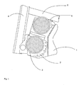
- FIG. 1 shows a typical installation space for an axle and hydraulic drive Forklift truck with a frame 1, in the front area of an axle construction 2 is attached with a drive motor 3.
- a lifting mast 4 is located close to the axis 2 attached, which can be changed in its inclination via a tilt cylinder 5.
- a Hydraulic drive 6 is provided, which is arranged above the axis 2.
- the hydraulic drive 6, as shown in Figure 2, consists of an electric motor 7 as Drive and a hydraulic pump 8.
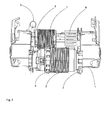
- the converter 10 is essentially within the radial dimensions of the motor 3 and with it in the longitudinal direction of the motor 3 arranged one behind the other in the common housing 9.
- the Connection cable 12, via the contact between in the example shown Inverter 10 and motor 3 are carried out completely within the housing 9. This ensures short cable lengths and optimal shielding.
- For the converter 10 is therefore not a separate housing that this before Protects environmental influences, necessary what the construction of the truck overall simplified, especially because a separate housing is essential takes up more space than the design according to the invention.
- the converter is cooled by a Fan wheel 13, which is arranged on the motor shaft 11. This will operate the Motor 3 of the converter 10 effectively cooled, when at a long standstill when the Converter 10 does not deliver a significant amount of power and therefore none Cooling is required, no power is required for cooling. Consequently the operating time is extended until the batteries are recharged.
- the speed of the engine is monitored by a sensor 14, the Connection cable 15 to the converter 10 also with the known advantages shortest path and run completely within the housing 9.
- the temperature of the motor 3 is detected by a sensor 16, which is connected via connecting cable 17 the converter 10 is connected. Attaching the sensor 16 to a coil 18 of the motor 3 is selected in the present exemplary embodiment such that a results in the smallest possible length of the cable 17, which in turn is completely within the Housing 9 is guided and thus offers the known advantages.
- the place where the sensor 16 is attached is not necessarily the so-called hot spot, that is, the point at which the highest temperature occurs in motor 3. To still be one To prevent the motor 3 from overheating, the measured value becomes the value anywhere, especially at the hot spot of the engine 3, calculated.
- the drive 7 of the hydraulic pump 8 shown in FIG. 2 can be used as required also be designed as a three-phase motor in the inventive design.
- traction drive Travel motors which are attached to a drive axle.
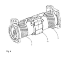
- a arrangement according to the invention of these traction motors and the associated converter is shown in Fig. 4.
- the two motors 3 and the converter are in one common housing 19 arranged.
- the arrangement of each engine 3 assigned components is used as a preferred embodiment similar to that in FIG Single motors are shown, in particular the arrangement of the Converter in the air flow of one or more fans and the attachment of the sensors to record the operating status of the motors, but there are also others Possible designs.
- the arrangement of motors 3 and converters in one Common housing offers the advantages mentioned for a single motor the advantage of an additional space saving and a common one Power supply from the voltage source to the traction motors and thus reduced Wiring.
- a temperature T mess is determined at one point on the motor of the electric drive. From this temperature, the temperature T over at least one other point in the engine is calculated using a mathematical model of the temperature development in the engine.
- this model will be optimized on the basis of the physical principles for the operation of electric motors on the basis of comparative measurements on real test motors in such a way that the real temperature is reproduced as precisely as possible under certain operating conditions and at certain points of the motor.
- the accuracy of the model is optimized for those operating conditions and locations in the engine where there is a risk of damage due to overheating.
- the temperature distribution in the entire motor can also be calculated, for example, in order to determine large local temperature gradients and to prevent them from rising by suitable measures.
- the test engines on the basis of which the model is optimized should be as largely as possible identical in construction to the engines for which the model is used and should be operated under the conditions typical in operation.
- a control which can be integrated, for example, in the converter of a three-phase motor.
- this can be the activation of a device for cooling. If such additional cooling is not available or is already in operation, the controller can, for example, change engine operating parameters so that the temperature of the engine drops.
Landscapes
- Engineering & Computer Science (AREA)
- Transportation (AREA)
- Structural Engineering (AREA)
- Chemical & Material Sciences (AREA)
- Combustion & Propulsion (AREA)
- Civil Engineering (AREA)
- Life Sciences & Earth Sciences (AREA)
- Geology (AREA)
- Mechanical Engineering (AREA)
- Electric Propulsion And Braking For Vehicles (AREA)
- Control Of Ac Motors In General (AREA)
Abstract
Description
- Figur 1
- eine typische Achsanordnung in einem Gabelstapler mit einem erfindungsgemäßen Antrieb in einer Schnittdarstellung,
- Figur 2
- eine typische Achsanordnung in einem Gabelstapler mit einem erfindungsgemäßen Antrieb von vom gesehen,
- Figur 3
- eine erfindungsgemäße Anordnung von Motor und Umrichter in einem Längsschnitt,
- Figur 4
- eine erfindungsgemäße Anordnung von zwei Motoren und dazugehörigen Umrichtern in einem Gehäuse,
- Figur 5
- ein Ablaufschema für ein erfindungsgemäßes Verfahren.
Claims (8)
- Flurförderzeug, insbesondere Gabelstapler, mit einem elektrischen Antrieb bestehend aus einer Spannungsquelle, einer Steuerelektronik und mindestens einem Drehstrommotor mit mindestens einem Umrichter, dadurch gekennzeichnet, dass der Umrichter (10) in unmittelbarer Nähe zum Drehstrommotor (3) im Wesentlichen innerhalb dessen radialer Abmessungen angeordnet ist.
- Flurförderzeug nach Anspruch 1, dadurch gekennzeichnet, dass der Umrichter (10) und der Drehstrommotor (3) in einem gemeinsamen Gehäuse (9), insbesondere in Längsrichtung des Motors (3) hintereinander, angeordnet sind und die elektrische Kontaktierung (12) zwischen Umrichter (10) und Motor (3) vollständig innerhalb des gemeinsamen Gehäuses (9) erfolgt.
- Flurförderzeug nach Anspruch 1 oder 2, dadurch gekennzeichnet, dass die Kühlung des Umrichters (10) durch mindestens ein auf der Motorwelle (11) angeordnetes Lüfterrad (13) erfolgt.
- Flurförderzeug nach einem der Ansprüche 1 bis 3, dadurch gekennzeichnet, dass mindestens ein Sensor (14) zur Erfassung von Betriebszuständen des Motors (3), insbesondere der Temperatur und/oder der Drehzahl, mit mindestens einer der Platinen des Umrichters (10) in Wirkverbindung steht, wobei die Verkabelung (15) vollständig innerhalb des gemeinsamen Gehäuses (9) von Motor (3) und Umrichter (10) verläuft.
- Flurförderzeug nach einem der Ansprüche 1 bis 4, dadurch gekennzeichnet, dass mindestens ein Sensor (16) zur Erfassung einer Temperatur, dessen Messwert zur Berechnung einer beim Betrieb des Motors (3) relevanten Temperatur an mindestens einer anderen Stelle als der Einbaustelle des Sensors, insbesondere des so genannten Heißpunktes, dient, mit mindestens einer der Platinen des Umrichters (10) in Wirkverbindung steht.
- Flurförderzeug nach einem der Ansprüche 1 bis 5, dadurch gekennzeichnet, dass eine Anordnung aus mehreren Motoren (3) und Umrichtern in einem gemeinsamen Gehäuse (19) angebracht ist.
- Verfahren zum Betrieb eines elektrischen Antriebs eines Flurförderzeugs bestehend aus einer Spannungsquelle, einer Steuerelektronik und mindestens einem Drehstrommotor mit mindestens einem Umrichter, dadurch gekennzeichnet, dass aus der an einer Stelle des Motors ermittelten Temperatur mindestens eine für den Betrieb des Motors relevante Temperatur an mindestens einer anderen Stelle des Motors, insbesondere am so genannten Heißpunkt, berechnet wird und die Steuerelektronik oder der Umrichter des Motors bei Überschreiten einer kritischen berechneten Temperatur und/oder eines kritischen Temperaturgradienten im Motor Betriebsparameter des Motors und/oder einer Kühlvorrichtung derart beeinflusst, dass ein weiteres Ansteigen der Temperatur an dieser oder anderen für den Betrieb relevanten Stellen und/oder eines kritischen Temperaturgradienten im Motor verhindert wird.
- Verfahren nach Anspruch 7, dadurch gekennzeichnet, dass die Berechnung anhand eines mathematischen Modells der Temperaturentwicklung im Motor erfolgt, dessen Parameter in Versuchen an realen Motoren optimiert wurden.
Applications Claiming Priority (2)
| Application Number | Priority Date | Filing Date | Title |
|---|---|---|---|
| DE2002141420 DE10241420A1 (de) | 2002-09-06 | 2002-09-06 | Flurförderzeug mit einem elektrischen Antrieb |
| DE10241420 | 2002-09-06 |
Publications (2)
| Publication Number | Publication Date |
|---|---|
| EP1396465A2 true EP1396465A2 (de) | 2004-03-10 |
| EP1396465A3 EP1396465A3 (de) | 2005-12-14 |
Family
ID=31502461
Family Applications (1)
| Application Number | Title | Priority Date | Filing Date |
|---|---|---|---|
| EP03019250A Withdrawn EP1396465A3 (de) | 2002-09-06 | 2003-08-26 | Flurförderzeug mit einem elektrischen Antrieb |
Country Status (2)
| Country | Link |
|---|---|
| EP (1) | EP1396465A3 (de) |
| DE (1) | DE10241420A1 (de) |
Cited By (4)
| Publication number | Priority date | Publication date | Assignee | Title |
|---|---|---|---|---|
| DE102006011993A1 (de) * | 2006-03-16 | 2007-09-20 | Agrarsystem Gmbh | Regelkreisantrieb für ein Arbeitsaggregat einer landwirtschaftlichen oder einer kommunalen Maschine oder einer Baumaschine |
| EP2079153A2 (de) | 2008-01-10 | 2009-07-15 | Jungheinrich Aktiengesellschaft | Elektrischer Antrieb für ein Flurförderzeug |
| WO2017101932A1 (de) * | 2015-12-18 | 2017-06-22 | Schaeffler Technologies AG & Co. KG | Pumpenaktor zur kupplungs- und gangstelleraktuierung in einem getriebe eines kraftfahrzeugs |
| US10676130B1 (en) | 2014-08-28 | 2020-06-09 | Hydro-Gear Limited Partnership | Electric transaxle with integral power generating device |
Families Citing this family (6)
| Publication number | Priority date | Publication date | Assignee | Title |
|---|---|---|---|---|
| DE102005017736A1 (de) | 2005-04-15 | 2006-12-14 | Zf Friedrichshafen Ag | Elektrisches Antriebssystem für Flurförderzeuge |
| DE102005017737A1 (de) | 2005-04-15 | 2006-10-26 | Zf Friedrichshafen Ag | Antrieb für ein Flurförderzeug |
| DE102006049983B4 (de) * | 2006-10-24 | 2016-10-27 | Linde Material Handling Gmbh | Arbeitsmaschine mit Kühlung im Fahrzeugruhestand |
| DE102007010357A1 (de) * | 2007-03-03 | 2008-09-04 | Jungheinrich Aktiengesellschaft | Antriebseinheit insbesondere für Flurförderzeug |
| DE102007055766A1 (de) | 2007-12-12 | 2009-06-18 | Zf Friedrichshafen Ag | Antriebseinheit für elektromotorisch angetriebene Fahrzeuge, insbesondere für Flurförderzeuge |
| DE102011103797B4 (de) | 2011-06-01 | 2020-08-20 | Jungheinrich Aktiengesellschaft | Verfahren zur Bestimmung einer Temperatur |
Family Cites Families (7)
| Publication number | Priority date | Publication date | Assignee | Title |
|---|---|---|---|---|
| DE3231960A1 (de) * | 1982-08-27 | 1984-03-01 | Hermann Dr.-Ing. 3302 Cremlingen Klaue | Durch elektromotoren angetriebene achse, insbesondere fuer schwere kraftfahrzeuge |
| US5327034A (en) * | 1992-07-14 | 1994-07-05 | Hydro-Quebec | Electrically motorized wheel assembly |
| DE4418271A1 (de) * | 1994-05-26 | 1995-11-30 | Voith Gmbh J M | Antriebseinheit |
| DE4442867C2 (de) * | 1994-12-02 | 1999-09-09 | Mannesmann Sachs Ag | Antriebsanordnung für ein Fahrzeug, insbesondere ein Straßenfahrzeug |
| DE19726258C2 (de) * | 1996-07-01 | 2001-10-04 | Barmag Barmer Maschf | Galetteneinheit zum Führen und Fördern eines Fadens |
| DE19714784A1 (de) * | 1997-04-10 | 1998-10-22 | Danfoss As | Kompaktantrieb |
| DE19721526A1 (de) * | 1997-05-22 | 1998-11-26 | Still Gmbh | Flurförderzeug mit einem elektrischen Aggregat |
-
2002
- 2002-09-06 DE DE2002141420 patent/DE10241420A1/de not_active Withdrawn
-
2003
- 2003-08-26 EP EP03019250A patent/EP1396465A3/de not_active Withdrawn
Cited By (9)
| Publication number | Priority date | Publication date | Assignee | Title |
|---|---|---|---|---|
| DE102006011993A1 (de) * | 2006-03-16 | 2007-09-20 | Agrarsystem Gmbh | Regelkreisantrieb für ein Arbeitsaggregat einer landwirtschaftlichen oder einer kommunalen Maschine oder einer Baumaschine |
| EP2079153A2 (de) | 2008-01-10 | 2009-07-15 | Jungheinrich Aktiengesellschaft | Elektrischer Antrieb für ein Flurförderzeug |
| DE102008003863A1 (de) | 2008-01-10 | 2009-07-16 | Jungheinrich Ag | Elektrischer Antrieb für ein Flurförderzeug |
| US10676130B1 (en) | 2014-08-28 | 2020-06-09 | Hydro-Gear Limited Partnership | Electric transaxle with integral power generating device |
| US11807296B1 (en) | 2014-08-28 | 2023-11-07 | Hydro-Gear Limited Partnership | Electric transaxle with integral power generating device |
| US12151739B1 (en) | 2014-08-28 | 2024-11-26 | Hydro-Gear Limited Partnership | Electric transaxle with integral power generating device |
| WO2017101932A1 (de) * | 2015-12-18 | 2017-06-22 | Schaeffler Technologies AG & Co. KG | Pumpenaktor zur kupplungs- und gangstelleraktuierung in einem getriebe eines kraftfahrzeugs |
| CN108291590A (zh) * | 2015-12-18 | 2018-07-17 | 舍弗勒技术股份两合公司 | 用于在机动车的变速器中进行离合器和换挡器致动的泵致动器 |
| CN108291590B (zh) * | 2015-12-18 | 2020-04-07 | 舍弗勒技术股份两合公司 | 用于在机动车的变速器中进行离合器和换挡器致动的泵致动器 |
Also Published As
| Publication number | Publication date |
|---|---|
| EP1396465A3 (de) | 2005-12-14 |
| DE10241420A1 (de) | 2004-03-18 |
Similar Documents
| Publication | Publication Date | Title |
|---|---|---|
| EP2108612B1 (de) | Winde | |
| DE102010003025B4 (de) | Verfahren zum Steuern einer Kühlung eines Stromrichters für ein Hybridelektrofahrzeug | |
| EP3935268B1 (de) | Kühlvorrichtung für ein kraftfahrzeug | |
| DE102017207886A1 (de) | Steuereinheit und Verfahren zum Ansteuern einer Wechselrichterschaltung für einen Permanentmagnet-Synchronmotor | |
| DE202014000738U1 (de) | Radlader mit Energiespeichereinheit | |
| EP1396465A2 (de) | Flurförderzeug mit einem elektrischen Antrieb | |
| DE102013208019A1 (de) | Fahrzeugbatteriepack-Kühlsystem | |
| DE112008000422T5 (de) | Spannungssteuervorrichtung und Spannungssteuerverfahren | |
| WO2019192977A1 (de) | Temperierungsvorrichtung und vorrichtungsanordnung in einem temperierungssystem | |
| DE102010049169A1 (de) | Verfahren zur Steuerung einer elektrischen Drehfeldmaschine einer mobilen Arbeitsmaschine | |
| DE4108074C2 (de) | Elektronisch gesteuerter Elektromotor | |
| EP3286030B1 (de) | Energieversorgungseinheit, kombination einer derartigen energieversorgungseinheit mit einer weiteren funktionseinheit und schwerlastfahrzeug | |
| DE102022104319A1 (de) | Elektrische drehvorrichtung und antriebsvorrichtung | |
| EP0879724B1 (de) | Flurförderzeug mit einem elektrischen Aggregrat | |
| EP3705631B1 (de) | Arbeitsmaschine mit elektroantrieb und kühlvorrichtung | |
| EP1781075B1 (de) | Kühlvorrichtung für ein Kraftfahrzeug mit einem aus zwei Motoren bestehenden Antrieb | |
| DE102021206778B4 (de) | Verfahren zum Betreiben des Antriebsstrangs, Antriebsstrang für eine Arbeitsmaschine und Arbeitsmaschine | |
| AT502321A1 (de) | Steuerung einer kühlmittelpumpe | |
| DE102011108188A1 (de) | Elektrisch betriebenes Fahrzeug insbesondere Flurförderzeug | |
| DE112018001591T5 (de) | Energiespeichersystem | |
| DE102016202835A1 (de) | Elektrische Rotationsmaschine mit integrierter Steuereinrichtung | |
| DE102014106794A1 (de) | Flurförderzeug mit Batterie und Sensiereinrichtung zur Überwachung der Temperatur der Batterie | |
| DE112015000065T5 (de) | Spannungssteuerungsvorrichtung und Spannungssteuerungsverfahren | |
| WO2024017689A1 (de) | Fahrzeug sowie verfahren zum betrieb des fahrzeugs | |
| EP4368433A1 (de) | Kühlmittelkreislauf für eine selbstfahrende arbeitsmaschine mit mehreren elektrischen antriebskomponenten |
Legal Events
| Date | Code | Title | Description |
|---|---|---|---|
| PUAI | Public reference made under article 153(3) epc to a published international application that has entered the european phase |
Free format text: ORIGINAL CODE: 0009012 |
|
| AK | Designated contracting states |
Kind code of ref document: A2 Designated state(s): AT BE BG CH CY CZ DE DK EE ES FI FR GB GR HU IE IT LI LU MC NL PT RO SE SI SK TR |
|
| AX | Request for extension of the european patent |
Extension state: AL LT LV MK |
|
| PUAL | Search report despatched |
Free format text: ORIGINAL CODE: 0009013 |
|
| AK | Designated contracting states |
Kind code of ref document: A3 Designated state(s): AT BE BG CH CY CZ DE DK EE ES FI FR GB GR HU IE IT LI LU MC NL PT RO SE SI SK TR |
|
| AX | Request for extension of the european patent |
Extension state: AL LT LV MK |
|
| RIC1 | Information provided on ipc code assigned before grant |
Ipc: 7H 02K 7/14 B Ipc: 7H 02P 11/06 B Ipc: 7H 02M 7/00 B Ipc: 7B 60K 1/04 B Ipc: 7B 66F 9/075 A |
|
| 17P | Request for examination filed |
Effective date: 20060511 |
|
| AKX | Designation fees paid |
Designated state(s): AT BE BG CH CY CZ DE DK EE ES FI FR GB GR HU IE IT LI LU MC NL PT RO SE SI SK TR |
|
| 17Q | First examination report despatched |
Effective date: 20060911 |
|
| STAA | Information on the status of an ep patent application or granted ep patent |
Free format text: STATUS: THE APPLICATION IS DEEMED TO BE WITHDRAWN |
|
| 18D | Application deemed to be withdrawn |
Effective date: 20090303 |