EP1396046B9 - Verfahren zur orientierung eines hexapods - Google Patents
Verfahren zur orientierung eines hexapods Download PDFInfo
- Publication number
- EP1396046B9 EP1396046B9 EP02743335.8A EP02743335A EP1396046B9 EP 1396046 B9 EP1396046 B9 EP 1396046B9 EP 02743335 A EP02743335 A EP 02743335A EP 1396046 B9 EP1396046 B9 EP 1396046B9
- Authority
- EP
- European Patent Office
- Prior art keywords
- moving plate
- orientation
- hexapod
- legs
- rotation
- Prior art date
- Legal status (The legal status is an assumption and is not a legal conclusion. Google has not performed a legal analysis and makes no representation as to the accuracy of the status listed.)
- Expired - Lifetime
Links
Images


Classifications
-
- H—ELECTRICITY
- H01—ELECTRIC ELEMENTS
- H01Q—ANTENNAS, i.e. RADIO AERIALS
- H01Q1/00—Details of, or arrangements associated with, antennas
- H01Q1/12—Supports; Mounting means
-
- H—ELECTRICITY
- H01—ELECTRIC ELEMENTS
- H01Q—ANTENNAS, i.e. RADIO AERIALS
- H01Q1/00—Details of, or arrangements associated with, antennas
- H01Q1/12—Supports; Mounting means
- H01Q1/125—Means for positioning
-
- H—ELECTRICITY
- H01—ELECTRIC ELEMENTS
- H01Q—ANTENNAS, i.e. RADIO AERIALS
- H01Q3/00—Arrangements for changing or varying the orientation or the shape of the directional pattern of the waves radiated from an antenna or antenna system
- H01Q3/02—Arrangements for changing or varying the orientation or the shape of the directional pattern of the waves radiated from an antenna or antenna system using mechanical movement of antenna or antenna system as a whole
- H01Q3/08—Arrangements for changing or varying the orientation or the shape of the directional pattern of the waves radiated from an antenna or antenna system using mechanical movement of antenna or antenna system as a whole for varying two co-ordinates of the orientation
-
- Y—GENERAL TAGGING OF NEW TECHNOLOGICAL DEVELOPMENTS; GENERAL TAGGING OF CROSS-SECTIONAL TECHNOLOGIES SPANNING OVER SEVERAL SECTIONS OF THE IPC; TECHNICAL SUBJECTS COVERED BY FORMER USPC CROSS-REFERENCE ART COLLECTIONS [XRACs] AND DIGESTS
- Y10—TECHNICAL SUBJECTS COVERED BY FORMER USPC
- Y10T—TECHNICAL SUBJECTS COVERED BY FORMER US CLASSIFICATION
- Y10T74/00—Machine element or mechanism
- Y10T74/20—Control lever and linkage systems
- Y10T74/20207—Multiple controlling elements for single controlled element
- Y10T74/20305—Robotic arm
- Y10T74/20329—Joint between elements
Definitions
- the invention relates to the application of hexapod turrets to the pointing of equipment such as antennas, optronic devices or telescopes, optical measuring or telecommunication devices or any device whose function requires orientation in space.
- the hexapod turrets or platforms of Stewart or Gough are devices generally used as antenna supports or telescopes allowing an adjustment of their orientation.
- the patent EP 0 515 888 filed on May 12, 1992 in the name of ANT NACHRICHTENTECH describes an example of a pointing device comprising a hexapod turret.
- a hexapod turret comprises a platform or fixed base, a movable plate on which is fixed the device to be oriented and six legs of adjustable length connecting the movable plate to the base. The ends of the legs are fixed in pairs by means of cardan-type links on the movable plate and the base so that the legs form triangles.
- Each leg includes two nested tubes slidable relative to each other. These tubes are powered by linear piezoelectric motors that adjust the length of the leg.
- Such a device makes it possible to move the movable plate according to six degrees of freedom.
- the object of the invention is to use a hexapod device to orient equipment with a large deflection and aiming on at least 2 ⁇ steradians so as to cover at least the half-space above the horizon.
- Another object of the invention is to orient the equipment in all directions of the half-space while permanently maintaining good rigidity.
- the document EP 0 266 026 A1 describes a method of moving the movable plate of a hexapod according to the preamble of claim 1.
- the invention proposes a method of moving the mobile plate of a hexapode according to claim 1.
- This method advantageously makes it possible to position the plate of the hexapod with an offset to avoid singular points, ie the positions in which the hexapod turret loses its rigidity.
- a deportation law giving a single position of the center OB of the plate in space according to its orientation is defined.
- This law defines a geometric surface called “offset surface” on which the center OB of the plate evolves.
- the displacement of the movable plate can be achieved by controlling a rotation of the movable plate along an axis perpendicular to the plane containing the sighting vectors V i and V i + 1 .
- This method of controlling the length variation of the legs avoids configurations of the hexapod turret which could reduce its rigidity and damage the mechanisms of the legs by collisions.
- the global movement of orientation of the moving plate is decomposed into a succession of unit displacements of azimuth ⁇ ⁇ and elevation ⁇ ⁇ of the movable platen. For each unitary displacement, the overall method of displacement (determination of a virtual rotation followed by a virtual translation) is reproduced.
- the invention further proposes a device for moving the movable plate of a hexapod, according to claim 13.
- the hexapod turret 100 comprises a base 10 and a movable plate 20 connected by six identical cylinders 1, 2, 3, 4, 5 and 6 constituting legs.
- Each jack i connects a point A i of the fixed base 10 to a point B i of the movable plate 20 and is set to a length L i corresponding to the distance A i B i .
- the connections between jacks and base 10 as well as the connections between jacks and movable plate 20 are materialized by twelve gimbal joints (or universal joint). Each of these joints comprise two elementary axes of rotation which intersect at points A 1 , A 2 , A 3 , A 4 , A 5 , A 6 , B 1 , B 2 , B 3 , B 4 , B 5 and B 6. .
- the points A i are located at a distance RA from the center OA of the fixed base 10 and are divided into three pairs, the pairs (A 1 , A 2 ), (A 3 , A 4 ) and (A 5 , A 6 ) being placed at 120 ° to each other.
- the points B i are located at a distance RB from the center OB of the moving plate 20 and are divided into three pairs, the pairs (B 2 , B 3 ), (B 4 , B 5 ), (B 6 , B 1 ) being placed at 120 ° to each other.
- Two jacks from a pair of points on the base 10 are always connected to points of distinct pairs on the movable plate 20. In this way, the jacks 1 to 6 converge two by two alternately towards the base 10 or towards the plateau mobile 20.
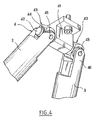
- connection is shown in more detail at the points B 2 and B 3 between the pair of jacks 2 and 3, and the movable plate 20.
- Such a connection comprises a central support 41 screwed onto the plate 10 and bearing symmetrically two cylindrical axes 42 oriented in the direction B 2 B 3 . Pivoting joints 43 are mounted on the pins 42.
- Each seal 43 has a bore which allows it to be fitted on one of the axes 42 of the central support 41.
- a pivot connection is made by a direct contact between a seal 43 and the surface of an axis 42.
- Each seal 43 is stopped in translation on the axis 42 by a circlip 44 mounted in a groove of the axis 42 or by a nut mounted on the threaded end of the shaft 42.
- the seals 43 further comprise two axes 45 perpendicular to their bore.
- the ends 46 of the cylinders 2 and 3 have a general form of clevis, consisting of two symmetrical parts inserting the seal 43 and having bores in which are fitted the shafts 45 of the seal 43.
- the ends 46 in the yoke of the cylinders 2 and 3 have chamfers so as to allow them maximum clearance relative to the seal 43 in all the orientation configurations thereof.
- connection is shown in greater detail at the points A 1 and A 2 between the pair of jacks 1 and 2, and the fixed base 10.
- This connection is comparable to the connection between jacks and movable plate shown in FIG. figure 4 .
- It comprises a central support 51 screwed onto the base 10 and symmetrically carrying two concentric cylindrical axes 52 oriented along the direction A 1 A 2 .
- Swivel joints 53 having a bore and two perpendicular axes 55 are mounted on the axes 52.
- the ends 56 of the cylinders 1 and 2 have a generally clevis shape, consisting of two symmetrical parts inserting a seal 52 and having bores in which are fitted the axes of the seal 52.
- the end portions 56 of the cylinders 1 and 2 support a device 57 for controlling the lengths L 1 and L 2 of the cylinders 1 and 2.
- the cylinder 1 comprising two sets LA and L B being able to slide relative to each other so as to vary the length L 1 of the cylinder 1.
- the device 57 for adjusting the length comprises a motor not 61 whose output axis 62 supports a worm 63 for driving in rotation a toothed wheel 64 disposed perpendicularly to the axis 62.
- This toothed wheel 64 drives a screw to ball 65 extending in the length of the assembly LA.
- the assembly L B comprises a nut 66 mounted integrally in which the ball screw 65 pivots. The rotation of the ball screw 65 in the nut 66 causes the translation of the nut 66 along the screw 65.
- the screw 65 has a speed of rotation proportional to that of the stepper motor 61. To determine the coefficient of proportionality between these speeds, it suffices to know the geometrical characteristics of the different mechanical parts (in particular the steps of the screw 65, the wheel 64 and the worm 63). Theoretically, by controlling the angular position of the output shaft 62 of the motor 61, the length L 1 of the cylinder 1 is obtained. To control this length, it is possible, for example, to use a position servo of the motor 61 in an open loop, or an absolute position measurement of the axis 62 by resolver for a closed-loop servocontrol. It is also possible to use optical encoders, incremental or absolute, single-turn or multi-turn.
- the Figures 6 to 8 represent the axes of rotation of the various constituent elements of the universal joints.
- the RPJ axis is linked to the central support 41 or 51 and the RSJ axes to the joints 43 or 53.
- the figure 10 is a graphical representation of the angle of rotation of the joint 43 at the point A 1 around RPJ as a function of the azimuth ⁇ for a fixed elevation ⁇ of the movable plate 20.
- the figure 11 is a graphical representation of the angle of rotation of the jack 1 at the point A 1 around RSJ as a function of the azimuth ⁇ for a fixed elevation ⁇ of the moving plate 20.
- the figure 12 gives the relative angle of rotation between the two elements LA and LB of the cylinder 1 as a function of the azimuth ⁇ for a fixed elevation ⁇ of the movable plate 20.
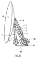
- hexapod turret 100 supports a satellite dish 30, it is shown in the reference position.
- the cylinders 1, 2, 3, 6, 5 and 6 are all set to the same length L 0 .
- the center OB is located vertically from the center OA on the vertical axis z 0 .
- the reference position can also be chosen as a virtual position of the turret.
- the reference position can be defined as a position for which the cylinders would take a length L 0 greater than the length that they can mechanically reach.
- a reference R 0 is defined, linked to the base 10, of center OA and of axes (x 0 , y 0 , z 0 ).
- the position of the movable plate 20 can be entirely determined by the position of its center OB and a viewing direction V defined by an azimuth ⁇ and an elevation ⁇ .
- the reference R 01 of center OB and of axes (x 01 , y 01 , z 01 ) is defined as the image by the rotation of the coordinate system R 0 with respect to the axis z 0 and of angle ⁇ .
- the reference R 02 of center OB and of axes (x 02 , y 02 , z 02 ) are defined as the image by the rotation of the reference R 01 with respect to the axis y 01 and of angle ⁇ .
- the reference R 02 is a reference fixed with respect to the movable plate 20.
- the direction x 02 defines the viewing direction V in the R 0 mark.
- the hexapod structure theoretically makes it possible to position the mobile plate 20 in the space according to six degrees of freedom. However, some positions lead to unstable configurations of the hexapod structure.
- the figure 15 represents a hexapod turret 100 in a configuration approaching instability.
- the movable plate 20 is substantially aligned with the cylinders 1 and 2 (the angle between leg and normal plateau reaches the limit value of 80 degrees).
- the structure 100 loses its rigidity when the angles between its elements (angles between axes jacks 1 to 6 and the normal to the plane of the fixed base 10 or movable plate 20) become close to 90 degrees. This phenomenon is particularly detrimental when the structure is placed outside and likely to be exposed to difficult climatic conditions.
- the hexapod turret 100 is used to point equipment towards elements situated at great distances from the dimensions of the turret, one is only interested in the orientation of its plate 20 and not in the position of the latter in the reference R 0 .
- the pointing direction V fixes the two orientation parameters ⁇ and ⁇ .
- An offset law d of the moving plate 20 is defined as a function of the aiming direction V to be pointed. For example, it is possible to control the variation of the lengths L 1 to L 6 of the legs 1 to 6 so that the center OB of the movable plate 20 moves in a plane perpendicular to the axis z 0 , that is to say at a height z constant with respect to the base 10. This plane defines the "offset surface" on which the OB point must always be.
- the point OB is offset by a distance d in the direction x 01 from its reference configuration illustrated in FIG. figure 13 .
- the direction x 01 of offset therefore depends on the azimuth angle ⁇ and the offset distance d is a function of the plateau elevation ⁇ .
- the Figures 16 and 17 give examples of laws of offset according to the elevation ⁇ .
- the hexapod turret 100 is in configurations in which the angles between the axes of the cylinders 1 to 6 and the normal to the plane of the fixed base 10 or movable plate 20 are always less than 45 degrees for example (giving a 45 degree safety margin).
- These laws make it possible to position the turret 100 away from singular points of low rigidity.
- the lengths L i of the jacks i obtainable are limited. Indeed, one must take into account the minimum and maximum possible elongations. On the other hand, one must respect the margin of safety chosen concerning the angles between the elements. One can choose a maximum angle of 135 or 150 degrees for example.
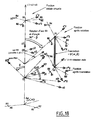
- FIG. 18 there is shown a displacement of the moving plate 20 of the turret 100.
- V 1 ( ⁇ 1 , ⁇ 1 ) towards a direction of view
- this reference R 02 we consider a virtual axis of rotation RH y 02 direction and passing through a fixed point PRH on the axis z 0 .
- a virtual rotation of the mobile plate 20 of RH axis and angle 90 ° - ⁇ 2 is performed. This rotation makes it possible to pass from the reference position of the turret (platform oriented at the zenith) to the position corresponding to the sighting direction V 2 .
- the reference position can be virtual.
- the offset of the moving plate (20) is determined in the direction of azimuth ⁇ 2 by virtue of the law of offset and the position of the points A 1 to A 6 and B 1 to B 6 are deduced therefrom. configuration.
- a virtual translation of the mobile plate 20 is carried out making it possible to bring the point OB back onto the offset surface.
- the lengths L 1 to L 6 of the legs 1 to 6 of the hexapod 100 are determined in this position of the plate 20. From this is deduced the elongation of each leg 1 to 6 necessary to pass from the orientation V 1 to V 2 with offset.
- t 1 second
- each leg length adjustment device i We realize a interpolation of the length of the legs: for example, an elongation speed of each jack i of / t ⁇ ⁇ The i (Linear interpolation).
- the turret 100 may pass through a singular point.
- the displacement of the plateau 20 from V 1 to V 2 can be decomposed into a series of unit displacements of azimuth ⁇ and elevation ⁇ ⁇ .
- Each unitary displacement makes it possible to go from a viewing direction V i to a viewing direction V i + 1 close to V i .
- the elongations of the cylinders are calculated by means of the two successive virtual transformations (a virtual rotation followed by a virtual translation) as previously described. In this way, the plate 20 is moved in a series of positions corresponding to target directions V 1 , ...
- V i , V i + 1 ... V 2 having a deviation of ⁇ ⁇ and ⁇ ⁇ .
- the values of ⁇ ⁇ and ⁇ ⁇ are chosen sufficiently small so that the plate 20 never goes through singular points or configurations that are physically impossible to achieve. Indeed, the smaller ⁇ ⁇ and ⁇ ⁇ are, the fewer the successive positions OB of the plateau 20 can approach a singular point.
- the successive positions of the viewing direction V i are illustrated. These positions are for example chosen with successive deviations of 1 °.
- the unitary trajectory of the orientation vector V i between two successive positions corresponds to a rotation of axis perpendicular to the plane containing the two successive orientations.
- the successive positions of V i can follow a direct global trajectory corresponding to an axis rotation perpendicular to V 1 and V 2 as illustrated on FIG. figure 19 or any global trajectory as illustrated on the figure 20 .
- the method of moving the movable plate 20 of the hexapod 100 previously described has the effect of linking the rotation of the movable plate 20 about its own axis x 02 to its azimuth rotation about the axis z 0 linked to the base 10
- V 1 ( ⁇ 1 , ⁇ 1 )
- V 2 ( ⁇ 2 , ⁇ 2 )
- the mobile plate 20 continuously compensates for this rotation of azimuth by rotating about its own axis z 02 of angle - ( ⁇ 2 - ⁇ 1 ).
- the overall rotation of the movable plate 20 about the axis z 0 is always zero.
- This method has for example the advantage that electrical cables connected to the device 30 mounted on the movable plate 20 and connecting the device to the ground never undergo torsion during the displacement of the movable plate 20.
- This feature makes it possible to control a continuous rotation the movable plate 20 about the azimuth axis z 0 without risking damage to the mechanism of the hexapod 100.
- the moving plate moving device does not require a rotary joint.
- Another advantage of this method is that it permanently controls the proper operation of the displacement device. Indeed, in the case where one of the leg length adjustment devices or one of the cylinders would be deficient, it is sometimes difficult to perceive a malfunction of the hexapod.
- the stops of the cylinders are in this case the only arrangements likely to stop the movement device in its movement.
- the hexapod structure risks passing through singular points leading to an inevitable damage to the universal joints.
- the orientation device comprises means for controlling that the overall rotation of the movable plate 20 about the axis z 0 is always zero.
- figure 21 represents an example of such control means.
- These means comprise a cable 80 connecting the center OB of the movable plate 20 to the center OA of the fixed base 10.
- This cable 80 has the properties of being flexible in bending and rigid in torsion. It is connected at a first end, at the center OB mobile plate 20 by a rigid connection and at a second end, at the center OA of the fixed base 10 by a pivot connection 82.
- the cable 80 is provided at this second end of 84.
- the second end of the cable 80 is always fixed with respect to the base 10 and the indicator element 84 is in contact with a detection circuit 86.
- the rotation of the plate 20 around the Z axis 0 generates the rotation of the cable 80 relative to the base 10.
- This rotation causes the rotation of the indicator element 84, which is no longer in contact with the detection circuit 86.
- the detection circuit 86 detects this cut of contact and sends an alert signal to a control device of the leg adjustment devices. In response to this signal, the controller stops movement of the hexapod 100.
- control means could be used.
Landscapes
- Control Of Position Or Direction (AREA)
- Manipulator (AREA)
- Variable-Direction Aerials And Aerial Arrays (AREA)
- Shaping Of Tube Ends By Bending Or Straightening (AREA)
Claims (22)
- Verfahren zum Verlagern der beweglichen Platte (20) eines Hexapods (100), dessen Beine (1, 2, 3, 4, 5, 6) mit einer Vorrichtung zur Längeneinstellung ausgestattet sind, und dies ausgehend von einer Orientierung Vi, die durch ihre Azimut-Elevation-Koordinaten (αi, βi) definiert ist, zu einer Orientierung Vi+1, die durch ihre Azimut-Elevation-Koordinaten (αi+1, βi+1) definiert ist, und das die Schritte umfasst, gemäß denen:- eine Steuerungsregel definiert wird, gemäß der eine Versatzstrecke d in Abhängigkeit von der Orientierung der Platte (20) definiert wird,- die Versatzstrecke d bestimmt wird, die der Orientierung Vi+1 entspricht,- die Einstellungsvorrichtungen gesteuert werden, um die Längen L1 bis L6 der Beine (1, 2, 3, 4, 5, 6) zu verändern, um die bewegliche Platte (20) von der Orientierung Vi in die Orientierung Vi+1 zu verlagern und sie relativ zur Senkrechten zum feststehenden Sockel (10) des Hexapods (100), die durch den Mittelpunkt OA des Sockels (10) geht, in der Azimutebene zu Vi+1 um die Strecke d zu versetzen,dadurch gekennzeichnet, dass es außerdem die Schritte umfasst, gemäß denen:ständig überprüft wird, dass die Gesamtdrehung der beweglichen Platte (20) in Bezug auf die Senkrechte zum feststehenden Sockel (10) null ist, und,falls festgestellt wird, dass die Gesamtdrehung der beweglichen Platte (20) in Bezug auf die Senkrechte zum feststehenden Sockel (10) nicht mehr null ist, ein Steuerbefehl erzeugt wird, um die Bewegung des Hexapods (100) zu stoppen.
- Verfahren nach Anspruch 1, dadurch gekennzeichnet, dass eine Versatz-Steuerungsregel definiert wird, die für den Mittelpunkt OB der Platte in Abhängigkeit von ihrer Orientierung eine eindeutige Position im Raum angibt.
- Verfahren nach Anspruch 2, dadurch gekennzeichnet, dass die Versatz-Steuerungsregel eine stetige geometrische Fläche definiert.
- Verfahren nach Anspruch 3, dadurch gekennzeichnet, dass die Versatzfläche eine Ebene ist.
- Verfahren nach Anspruch 3, dadurch gekennzeichnet, dass die Versatzfläche ein Kugelabschnitt ist.
- Verfahren nach einem der vorhergehenden Ansprüche, dadurch gekennzeichnet, dass die bewegliche Platte (20) verlagert wird, indem eine Drehung der beweglichen Platte (20) um eine Achse senkrecht zur Ebene, die die Visiervektoren Vi und Vi+1 enthält, gesteuert wird.
- Verfahren nach einem der vorhergehenden Ansprüche, dadurch gekennzeichnet, dass das Verändern der Länge der Beine (1, 2, 3, 4, 5, 6) des Hexapods (100) durch die folgenden Schritte festgelegt wird:- Definieren einer Referenzposition des Hexapods (100), gemäß der alle Beine (1, 2, 3, 4, 5, 6) auf dieselbe Länge L0 eingestellt sind,- Bestimmen der Längenveränderung für jedes Bein (1, 2, 3, 4, 5, 6), damit die bewegliche Platte (20) des Hexapods (100) sich von der Referenzposition in die Visierrichtung Vi+1 verlagert, und dies durch eine virtuelle Drehung in der Azimutebene αi+1 und durch eine virtuelle Translation des Mittelpunkts OB der Platte (20) in Richtung einer Versatzfläche, die durch die Versatz-Steuerungsregel definiert ist,- Ableiten einer Gesamtlängenveränderung für jedes Bein (1, 2, 3, 4, 5, 6) daraus, um von der Richtung Vi zur Richtung Vi+1 zu kommen.
- Verfahren nach einem der vorhergehenden Ansprüche, dadurch gekennzeichnet, dass die Gesamtbewegung der Orientierung der beweglichen Platte (20) in eine Aufeinanderfolge von unitarisch Verlagerungen im Azimut Δα und in der Elevation Δβ der beweglichen Platte (20) aufgeteilt wird.
- Verfahren nach einem der vorhergehenden Ansprüche, dadurch gekennzeichnet, dass die Einstellvorrichtungen in Abhängigkeit von den Längen Li der Beine (1, 2, 3, 4, 5, 6), die erreicht werden sollen, gesteuert werden, und dadurch, dass diese Berechnung die relativen Winkel zwischen den Elementen berücksichtigt, aus denen die Verbindungen aufgebaut sind, die die Beine (1, 2, 3, 4, 5, 6) mit der Platte (20) und mit dem Sockel (10) verbinden.
- Verfahren nach Anspruch 9, dadurch gekennzeichnet, dass die relativen Winkel zwischen den Elementen, aus denen die Verbindungen aufgebaut sind, die die Beine (1, 2, 3, 4, 5, 6) mit der Platte (20) und mit dem Sockel (10) verbinden, ausgehend von den berechneten Positionen von Verbindungspunkten zwischen den Beinen (1, 2, 3; 4, 5, 6) und der Platte (20) bestimmt werden, wobei daraus die relativen Drehungen zwischen den Verschiebungseinheiten von Zylindern abgeleitet werden.
- Verfahren nach Anspruch 10, dadurch gekennzeichnet, dass jedes Bein (1, 2, 3, 4, 5, 6) des Hexapods (100) einen Zylinder umfasst, der aus zwei Einheiten aufgebaut ist, die sich gegeneinander verschieben, sowie einen Stellantrieb (61), dessen Ausgangsachse (62) eine Schraube (65) drehend antreibt, die eine schraubenförmige Verbindung zwischen den Verschiebungseinheiten bildet, wobei eine zusätzliche Verlängerung jedes Zylinders aufgrund der relativen Drehungen zwischen seinen Verschiebungseinheiten (LA, LB) in Abhängigkeit von den geometrischen Eigenschaften der schraubenförmigen Verbindung abgeleitet wird, und dadurch, dass diese zusätzliche Verlängerung berücksichtigt wird, um einen Einstellwert zum Steuern des Stellantriebs (61) festzulegen.
- Verfahren nach einem der vorhergehenden Ansprüche, dadurch gekennzeichnet, dass die Winkel, die von den Achsen der Beine (1, 2, 3, 4, 5, 6) und der Normalen zur Ebene des feststehenden Sockels (10) gebildet werden, und die Winkel, die von den Achsen der Beine (1, 2, 3, 4, 5, 6) und der Normalen zur Ebene der beweglichen Platte (20) gebildet werden, jederzeit kleiner als ein maximaler Winkel sind, der zwischen 40 und 80 Grad festgelegt ist.
- Vorrichtung zum Verlagern der beweglichen Platte (20) eines Hexapods (100), dessen Beine (1, 2, 3, 4, 5, 6) mit einer Vorrichtung zur Längeneinstellung ausgestattet sind, und dies ausgehend von einer Orientierung Vi, die durch ihre Azimut-Elevation-Koordinaten (αi, βi) definiert ist, zu einer Orientierung Vi+1, die durch ihre Azimut-Elevation-Koordinaten (αi+1, βi+1) definiert ist, und die Steuerungsmittel umfasst, die dafür eingerichtet sind, die folgenden Schritte auszuführen:- eine Steuerungsregel zu definieren, gemäß der eine Versatzstrecke d in Abhängigkeit von der Orientierung der Platte (20) definiert wird,- die Versatzstrecke d zu bestimmen, die der Orientierung Vi+1 entspricht,- die Einstellungsvorrichtungen zu steuern, um die Längen L1 bis L6 der Beine (1, 2, 3, 4, 5, 6) zu verändern, um die bewegliche Platte (20) von der Orientierung Vi in die Orientierung Vi+1 zu verlagern und sie relativ zur Senkrechten zum feststehenden Sockel (10) des Hexapods (100), die durch den Mittelpunkt OA des Sockels (10) geht, in der Azimutebene zu Vi+1 um die Strecke d zu versetzen,wobei die Vorrichtung dadurch gekennzeichnet ist, dass sie ein Mittel umfasst, um zu überprüfen, dass die Gesamtdrehung der beweglichen Platte (20) in Bezug auf die Senkrechte zum feststehenden Sockel (10) null ist, und dadurch, dass die Steuerungsmittel dafür eingerichtet sind, einen Steuerbefehl zu erzeugen, um die Bewegung des Hexapods zu stoppen, wenn die Gesamtdrehung der beweglichen Platte (20) in Bezug auf die Senkrechte zum feststehenden Sockel (10) nicht mehr null ist.
- Vorrichtung nach Anspruch 13, dadurch gekennzeichnet, dass jedes Bein (1, 2, 3, 4, 5, 6) des Hexapods (100) einen Zylinder umfasst, der eine erste und eine zweite Einheit (LA, LB) umfasst, die gegeneinander verschiebbar sind, und einen Stellantrieb (61), dessen Ausgangsachse (62) eine Schraube (65) drehend antreibt, die senkrecht zur Achse (62) des Motors (61) angeordnet ist, wobei die Schraube (65) sich in der Längsrichtung der ersten Einheit (LA) erstreckt und sich in einer Mutter (66) drehen kann, die fest verbunden mit der zweiten Einheit (LB) montiert ist, wobei die Drehung der Schraube (65) in der Mutter (66) die Translation der zweiten Einheit (LB) relativ zur ersten Einheit (LA) antreibt.
- Vorrichtung nach Anspruch 14, dadurch gekennzeichnet, dass die Steuerungsmittel dafür eingerichtet sind, eine zusätzliche Verlängerung jedes Zylinders aufgrund der relativen Drehungen zwischen seinen Verschiebungseinheiten (LA, LB) in Abhängigkeit von den geometrischen Eigenschaften der schraubenförmigen Verbindung zu bestimmen, und diese zusätzliche Verlängerung zu berücksichtigen, um einen Einstellwert zum Steuern des Stellantriebs (61) festzulegen.
- Vorrichtung nach einem der Ansprüche 14 oder 15, dadurch gekennzeichnet, dass sie ein Mittel zum Messen der. Position der Achse (62) des Stellantriebs (61) umfasst.
- Vorrichtung nach einem der Ansprüche 13 bis 16, dadurch gekennzeichnet; dass auf dem feststehenden Sockel (10) Verbindungen gemäß einem ersten Kreis mit Radius RA angeordnet sind und auf der beweglichen Platte (20) Verbindungen gemäß einem zweiten Kreis mit Radius RB angeordnet sind, wobei das Verhältnis RA/RB im Wesentlichen gleich 1,5 ist.
- Vorrichtung nach einem der Ansprüche 13 bis 17, dadurch gekennzeichnet, dass die Verbindungen paarweise auf der beweglichen Platte (20) oder auf dem feststehenden Sockel (10) gemäß einem Kreis mit Radius R angeordnet sind, wobei der Abstand zwischen zwei Verbindungen eines selben Paares im Wesentlichen gleich R/10 ist.
- Vorrichtung nach einem der Ansprüche 13 bis 18, dadurch gekennzeichnet, dass die maximale Verlängerung eines Beins kleiner oder gleich 2 ist.
- Vorrichtung nach einem der Ansprüche 13 bis 19, dadurch gekennzeichnet, dass die maximale Verlängerung eines Beins größer oder gleich 1,7 ist.
- Vorrichtung nach einem der Ansprüche 13 bis 20, dadurch gekennzeichnet, dass sie Folgendes umfasst: ein torsionssteifes Element, das an einem ersten Ende über eine starre Verbindung an der beweglichen Platte (20) und an einem zweiten Ende über eine drehbare Verbindung am feststehenden Sockel (10) befestigt ist, sowie ein Mittel zum Feststellen einer Drehung des zweiten Endes des Elements relativ zum Sockel (20).
- Vorrichtung nach Anspruch 21, dadurch gekennzeichnet, dass das Mittel zum Feststellen ein Anzeigeelement umfasst, das am zweiten Ende eines Kabels befestigt ist, sowie eine Detektorschaltung, und dadurch, dass wenn das zweite Ende des Kabels relativ zum Sockel (10) feststehend ist, das Anzeigeelement einen Kontakt mit einer Detektorschaltung herstellt, und wenn das zweite Ende des Kabels sich relativ zum Sockel (10) dreht, das Anzeigeelement den Kontakt unterbricht.
Applications Claiming Priority (3)
| Application Number | Priority Date | Filing Date | Title |
|---|---|---|---|
| FR0107136A FR2825445B1 (fr) | 2001-05-31 | 2001-05-31 | Procede d'orientation d'une tourelle hexapode |
| FR0107136 | 2001-05-31 | ||
| PCT/FR2002/001816 WO2002097920A1 (fr) | 2001-05-31 | 2002-05-30 | Procede d'orientation d'une tourelle hexapode |
Publications (3)
| Publication Number | Publication Date |
|---|---|
| EP1396046A1 EP1396046A1 (de) | 2004-03-10 |
| EP1396046B1 EP1396046B1 (de) | 2013-01-02 |
| EP1396046B9 true EP1396046B9 (de) | 2013-07-10 |
Family
ID=8863813
Family Applications (1)
| Application Number | Title | Priority Date | Filing Date |
|---|---|---|---|
| EP02743335.8A Expired - Lifetime EP1396046B9 (de) | 2001-05-31 | 2002-05-30 | Verfahren zur orientierung eines hexapods |
Country Status (6)
| Country | Link |
|---|---|
| US (1) | US7081866B2 (de) |
| EP (1) | EP1396046B9 (de) |
| KR (1) | KR100880290B1 (de) |
| ES (1) | ES2402406T3 (de) |
| FR (1) | FR2825445B1 (de) |
| WO (1) | WO2002097920A1 (de) |
Families Citing this family (12)
| Publication number | Priority date | Publication date | Assignee | Title |
|---|---|---|---|---|
| US7469381B2 (en) | 2007-01-07 | 2008-12-23 | Apple Inc. | List scrolling and document translation, scaling, and rotation on a touch-screen display |
| US7487444B2 (en) | 2002-03-19 | 2009-02-03 | Aol Llc | Reformatting columns of content for display |
| ES2231026A1 (es) * | 2003-10-27 | 2005-05-01 | Ramem, S.A. | Posicionador tipo hexapodo para seguimiento solar de reflectores solares. |
| ITRM20050338A1 (it) * | 2005-06-28 | 2006-12-29 | Finmeccanica Spa | Struttura isostatica di sostegno per riflettori di antenne di grandi dimensioni fissi o ripuntabili. |
| US7671797B1 (en) * | 2006-09-18 | 2010-03-02 | Nvidia Corporation | Coordinate-based system, method and computer program product for adjusting an antenna |
| DE102006046758A1 (de) * | 2006-09-29 | 2008-04-03 | Abb Patent Gmbh | Vorrichtung insbesondere zum Positionieren von Objekten |
| SE530700C2 (sv) * | 2006-12-21 | 2008-08-19 | Hexagon Metrology Ab | Förfarande och anordning för kompensering av geometriska fel i bearbetningsmaskiner |
| FR2929195B1 (fr) * | 2008-03-27 | 2010-05-07 | Peugeot Citroen Automobiles Sa | Projecteur d'eclairage a orientation variable commandee, pour vehicule automobile |
| US8215199B2 (en) * | 2008-11-17 | 2012-07-10 | Marcroft Sacha L | Parallel kinematic positioning system |
| US9027545B2 (en) | 2010-11-24 | 2015-05-12 | William J. DeVillier | Solar collector positioning apparatus |
| TWI493148B (zh) * | 2011-11-22 | 2015-07-21 | William J Devillier | 太陽能收集器定位裝置 |
| US9376221B1 (en) * | 2012-10-31 | 2016-06-28 | The Boeing Company | Methods and apparatus to point a payload at a target |
Family Cites Families (7)
| Publication number | Priority date | Publication date | Assignee | Title |
|---|---|---|---|---|
| JPH0742812B2 (ja) * | 1986-06-04 | 1995-05-10 | 富士重工業株式会社 | 展開構造物 |
| EP0266026A1 (de) * | 1986-08-01 | 1988-05-04 | HER MAJESTY THE QUEEN in right of New Zealand Department of Scientific and Industrial Research | Nachführantenne |
| DE4117538C1 (de) | 1991-05-29 | 1992-07-09 | Ant Nachrichtentechnik Gmbh, 7150 Backnang, De | |
| GB9324218D0 (en) * | 1993-11-25 | 1994-01-12 | Renishaw Plc | Position determination machines |
| WO1998040761A1 (en) * | 1997-03-11 | 1998-09-17 | Orbit Communications, Tracking And Telemetry Ltd. | Satellite tracking system |
| US6041500A (en) * | 1998-01-23 | 2000-03-28 | Giddings & Lewis, Inc. | Automatic assembly machine and method utilizing six-axis positioning device |
| US6542132B2 (en) * | 2001-06-12 | 2003-04-01 | Harris Corporation | Deployable reflector antenna with tensegrity support architecture and associated methods |
-
2001
- 2001-05-31 FR FR0107136A patent/FR2825445B1/fr not_active Expired - Fee Related
-
2002
- 2002-05-30 US US10/479,648 patent/US7081866B2/en not_active Expired - Lifetime
- 2002-05-30 EP EP02743335.8A patent/EP1396046B9/de not_active Expired - Lifetime
- 2002-05-30 ES ES02743335T patent/ES2402406T3/es not_active Expired - Lifetime
- 2002-05-30 WO PCT/FR2002/001816 patent/WO2002097920A1/fr not_active Application Discontinuation
- 2002-05-30 KR KR1020037001452A patent/KR100880290B1/ko active IP Right Grant
Also Published As
| Publication number | Publication date |
|---|---|
| KR100880290B1 (ko) | 2009-01-23 |
| US7081866B2 (en) | 2006-07-25 |
| FR2825445A1 (fr) | 2002-12-06 |
| US20040244525A1 (en) | 2004-12-09 |
| EP1396046A1 (de) | 2004-03-10 |
| EP1396046B1 (de) | 2013-01-02 |
| WO2002097920A8 (fr) | 2005-04-07 |
| ES2402406T3 (es) | 2013-05-03 |
| KR20030051608A (ko) | 2003-06-25 |
| WO2002097920A1 (fr) | 2002-12-05 |
| FR2825445B1 (fr) | 2004-02-13 |
Similar Documents
| Publication | Publication Date | Title |
|---|---|---|
| EP1396046B9 (de) | Verfahren zur orientierung eines hexapods | |
| EP0362342B1 (de) | Gelenkvorrichtung insbesondere verwendbar auf dem gebiet der roboter | |
| CA1256914A (fr) | Mecanisme polyarticule retractile | |
| EP3055726B1 (de) | Beinahe lineare antriebssysteme zur positionierung von reflektoren | |
| EP2880337B1 (de) | Drehbewegungsvorrichtung zum bewegen einer reflektierenden oberfläche | |
| FR2728695A1 (fr) | Dispositif de commande en rotation de grande precision, notamment pour telescope | |
| EP2767794B1 (de) | Projektil mit Steuerflächen sowie Verfahren zur Steuerung der Steuerflächen eines solchen Projektils | |
| EP3045396B1 (de) | Ausrichtungseinheit eines instrumentes | |
| FR2995090A1 (fr) | Disposition de positionnement angulaire comprenant deux ensembles mecaniques de transmission de mouvement imbriques a deux points morts chacun | |
| EP2703768A1 (de) | Projektil mit ausrichtbaren Steuerflächen, und Steuerverfahren der Steuerflächen eines solchen Projektils | |
| FR2498379A1 (fr) | Dispositif d'orientation selon deux axes orthogonaux, utilisation dans une antenne hyperfrequence et antenne hyperfrequence comportant un tel dispositif | |
| EP0172291B1 (de) | Mehrgelenkiger faltbarer Mechanismus | |
| EP3213370A1 (de) | Vorrichtung zur anpassung eines beweglichen elements wie z. b. eines antennendecks | |
| FR2550980A1 (fr) | Dispositif de supportage d'un capteur pour une machine automatique et son application a une telle machine | |
| FR2490335A1 (fr) | Horizon artificiel pour aeronef | |
| FR2690532A1 (fr) | Dispositif de pointage pour appareil optique. | |
| WO2012131741A1 (en) | Sun follower with parallel kinematics and process for controlling such follower | |
| EP3870408B1 (de) | Verfahren zur bewirkung, dass ein werkzeug am ende eines gelenkarms ohne gleiten gegen eine oberfläche drückt, und vorrichtung zur durchführung davon | |
| EP2703691B1 (de) | Vorrichtung zur Winkeleinstellung mit drei Totpunkten | |
| FR2977823A1 (fr) | Table motorisee pour le positionnement micrometrique | |
| EP0455543B1 (de) | Vorrichtung zur Ausrichtung einer Reflektorantenne | |
| FR2530831A1 (fr) | Dispositif de deviateur optique variable, application a une optique d'autodirecteur | |
| FR2769969A1 (fr) | Mecanisme de pointage a deux mouvements de rotation independants, sans point mort | |
| EP0229617A1 (de) | Vorrichtung zur Orientierung einer Antenne zur Abtastung in zwei orthogonalen Richtungen | |
| WO2007003906A2 (en) | A positioning system |
Legal Events
| Date | Code | Title | Description |
|---|---|---|---|
| PUAI | Public reference made under article 153(3) epc to a published international application that has entered the european phase |
Free format text: ORIGINAL CODE: 0009012 |
|
| 17P | Request for examination filed |
Effective date: 20031222 |
|
| AK | Designated contracting states |
Kind code of ref document: A1 Designated state(s): AT BE CH CY DE DK ES FI FR GB GR IE IT LI LU MC NL PT SE TR |
|
| AX | Request for extension of the european patent |
Extension state: AL LT LV MK RO SI |
|
| 17Q | First examination report despatched |
Effective date: 20040414 |
|
| RAP1 | Party data changed (applicant data changed or rights of an application transferred) |
Owner name: ENERTEC |
|
| RAP1 | Party data changed (applicant data changed or rights of an application transferred) |
Owner name: ZODIAC DATA SYSTEMS |
|
| GRAP | Despatch of communication of intention to grant a patent |
Free format text: ORIGINAL CODE: EPIDOSNIGR1 |
|
| GRAS | Grant fee paid |
Free format text: ORIGINAL CODE: EPIDOSNIGR3 |
|
| GRAA | (expected) grant |
Free format text: ORIGINAL CODE: 0009210 |
|
| AK | Designated contracting states |
Kind code of ref document: B1 Designated state(s): AT BE CH CY DE DK ES FI FR GB GR IE IT LI LU MC NL PT SE TR |
|
| REG | Reference to a national code |
Ref country code: GB Ref legal event code: FG4D Free format text: NOT ENGLISH |
|
| REG | Reference to a national code |
Ref country code: CH Ref legal event code: EP Ref country code: AT Ref legal event code: REF Ref document number: 592051 Country of ref document: AT Kind code of ref document: T Effective date: 20130115 |
|
| REG | Reference to a national code |
Ref country code: IE Ref legal event code: FG4D Free format text: LANGUAGE OF EP DOCUMENT: FRENCH |
|
| REG | Reference to a national code |
Ref country code: DE Ref legal event code: R096 Ref document number: 60244332 Country of ref document: DE Effective date: 20130228 |
|
| REG | Reference to a national code |
Ref country code: CH Ref legal event code: NV Representative=s name: MICHELI AND CIE SA, CH |
|
| REG | Reference to a national code |
Ref country code: ES Ref legal event code: FG2A Ref document number: 2402406 Country of ref document: ES Kind code of ref document: T3 Effective date: 20130503 |
|
| REG | Reference to a national code |
Ref country code: AT Ref legal event code: MK05 Ref document number: 592051 Country of ref document: AT Kind code of ref document: T Effective date: 20130102 |
|
| REG | Reference to a national code |
Ref country code: NL Ref legal event code: VDEP Effective date: 20130102 |
|
| PG25 | Lapsed in a contracting state [announced via postgrant information from national office to epo] |
Ref country code: AT Free format text: LAPSE BECAUSE OF FAILURE TO SUBMIT A TRANSLATION OF THE DESCRIPTION OR TO PAY THE FEE WITHIN THE PRESCRIBED TIME-LIMIT Effective date: 20130102 Ref country code: SE Free format text: LAPSE BECAUSE OF FAILURE TO SUBMIT A TRANSLATION OF THE DESCRIPTION OR TO PAY THE FEE WITHIN THE PRESCRIBED TIME-LIMIT Effective date: 20130102 Ref country code: CY Free format text: LAPSE BECAUSE OF FAILURE TO SUBMIT A TRANSLATION OF THE DESCRIPTION OR TO PAY THE FEE WITHIN THE PRESCRIBED TIME-LIMIT Effective date: 20130102 |
|
| PG25 | Lapsed in a contracting state [announced via postgrant information from national office to epo] |
Ref country code: PT Free format text: LAPSE BECAUSE OF FAILURE TO SUBMIT A TRANSLATION OF THE DESCRIPTION OR TO PAY THE FEE WITHIN THE PRESCRIBED TIME-LIMIT Effective date: 20130502 Ref country code: FI Free format text: LAPSE BECAUSE OF FAILURE TO SUBMIT A TRANSLATION OF THE DESCRIPTION OR TO PAY THE FEE WITHIN THE PRESCRIBED TIME-LIMIT Effective date: 20130102 Ref country code: GR Free format text: LAPSE BECAUSE OF FAILURE TO SUBMIT A TRANSLATION OF THE DESCRIPTION OR TO PAY THE FEE WITHIN THE PRESCRIBED TIME-LIMIT Effective date: 20130403 Ref country code: NL Free format text: LAPSE BECAUSE OF FAILURE TO SUBMIT A TRANSLATION OF THE DESCRIPTION OR TO PAY THE FEE WITHIN THE PRESCRIBED TIME-LIMIT Effective date: 20130102 |
|
| PG25 | Lapsed in a contracting state [announced via postgrant information from national office to epo] |
Ref country code: DK Free format text: LAPSE BECAUSE OF FAILURE TO SUBMIT A TRANSLATION OF THE DESCRIPTION OR TO PAY THE FEE WITHIN THE PRESCRIBED TIME-LIMIT Effective date: 20130102 |
|
| PLBE | No opposition filed within time limit |
Free format text: ORIGINAL CODE: 0009261 |
|
| STAA | Information on the status of an ep patent application or granted ep patent |
Free format text: STATUS: NO OPPOSITION FILED WITHIN TIME LIMIT |
|
| 26N | No opposition filed |
Effective date: 20131003 |
|
| PG25 | Lapsed in a contracting state [announced via postgrant information from national office to epo] |
Ref country code: MC Free format text: LAPSE BECAUSE OF FAILURE TO SUBMIT A TRANSLATION OF THE DESCRIPTION OR TO PAY THE FEE WITHIN THE PRESCRIBED TIME-LIMIT Effective date: 20130102 |
|
| REG | Reference to a national code |
Ref country code: DE Ref legal event code: R097 Ref document number: 60244332 Country of ref document: DE Effective date: 20131003 |
|
| REG | Reference to a national code |
Ref country code: IE Ref legal event code: MM4A |
|
| PG25 | Lapsed in a contracting state [announced via postgrant information from national office to epo] |
Ref country code: IE Free format text: LAPSE BECAUSE OF NON-PAYMENT OF DUE FEES Effective date: 20130530 |
|
| PGFP | Annual fee paid to national office [announced via postgrant information from national office to epo] |
Ref country code: LU Payment date: 20140527 Year of fee payment: 13 |
|
| PGFP | Annual fee paid to national office [announced via postgrant information from national office to epo] |
Ref country code: TR Payment date: 20140528 Year of fee payment: 13 Ref country code: CH Payment date: 20140612 Year of fee payment: 13 |
|
| PGFP | Annual fee paid to national office [announced via postgrant information from national office to epo] |
Ref country code: BE Payment date: 20140626 Year of fee payment: 13 |
|
| REG | Reference to a national code |
Ref country code: CH Ref legal event code: PL |
|
| PG25 | Lapsed in a contracting state [announced via postgrant information from national office to epo] |
Ref country code: LI Free format text: LAPSE BECAUSE OF NON-PAYMENT OF DUE FEES Effective date: 20150531 Ref country code: CH Free format text: LAPSE BECAUSE OF NON-PAYMENT OF DUE FEES Effective date: 20150531 Ref country code: LU Free format text: LAPSE BECAUSE OF NON-PAYMENT OF DUE FEES Effective date: 20150530 |
|
| REG | Reference to a national code |
Ref country code: FR Ref legal event code: PLFP Year of fee payment: 15 |
|
| REG | Reference to a national code |
Ref country code: FR Ref legal event code: PLFP Year of fee payment: 16 |
|
| PG25 | Lapsed in a contracting state [announced via postgrant information from national office to epo] |
Ref country code: BE Free format text: LAPSE BECAUSE OF NON-PAYMENT OF DUE FEES Effective date: 20150531 |
|
| PG25 | Lapsed in a contracting state [announced via postgrant information from national office to epo] |
Ref country code: TR Free format text: LAPSE BECAUSE OF NON-PAYMENT OF DUE FEES Effective date: 20150530 |
|
| REG | Reference to a national code |
Ref country code: FR Ref legal event code: PLFP Year of fee payment: 17 |
|
| PGFP | Annual fee paid to national office [announced via postgrant information from national office to epo] |
Ref country code: DE Payment date: 20200421 Year of fee payment: 19 Ref country code: ES Payment date: 20200602 Year of fee payment: 19 Ref country code: FR Payment date: 20200422 Year of fee payment: 19 |
|
| PGFP | Annual fee paid to national office [announced via postgrant information from national office to epo] |
Ref country code: GB Payment date: 20200423 Year of fee payment: 19 Ref country code: IT Payment date: 20200421 Year of fee payment: 19 |
|
| REG | Reference to a national code |
Ref country code: ES Ref legal event code: PC2A Owner name: SAFRAN DATA SYSTEMS Effective date: 20210414 |
|
| REG | Reference to a national code |
Ref country code: DE Ref legal event code: R119 Ref document number: 60244332 Country of ref document: DE |
|
| GBPC | Gb: european patent ceased through non-payment of renewal fee |
Effective date: 20210530 |
|
| PG25 | Lapsed in a contracting state [announced via postgrant information from national office to epo] |
Ref country code: GB Free format text: LAPSE BECAUSE OF NON-PAYMENT OF DUE FEES Effective date: 20210530 Ref country code: DE Free format text: LAPSE BECAUSE OF NON-PAYMENT OF DUE FEES Effective date: 20211201 |
|
| PG25 | Lapsed in a contracting state [announced via postgrant information from national office to epo] |
Ref country code: FR Free format text: LAPSE BECAUSE OF NON-PAYMENT OF DUE FEES Effective date: 20210531 |
|
| REG | Reference to a national code |
Ref country code: ES Ref legal event code: FD2A Effective date: 20220802 |
|
| PG25 | Lapsed in a contracting state [announced via postgrant information from national office to epo] |
Ref country code: ES Free format text: LAPSE BECAUSE OF NON-PAYMENT OF DUE FEES Effective date: 20210531 |
|
| PG25 | Lapsed in a contracting state [announced via postgrant information from national office to epo] |
Ref country code: IT Free format text: LAPSE BECAUSE OF NON-PAYMENT OF DUE FEES Effective date: 20200530 |