EP1394900A1 - Connecteur de deux câbles d'énergie électrique et connexion comportant un tel connecteur - Google Patents
Connecteur de deux câbles d'énergie électrique et connexion comportant un tel connecteur Download PDFInfo
- Publication number
- EP1394900A1 EP1394900A1 EP03300099A EP03300099A EP1394900A1 EP 1394900 A1 EP1394900 A1 EP 1394900A1 EP 03300099 A EP03300099 A EP 03300099A EP 03300099 A EP03300099 A EP 03300099A EP 1394900 A1 EP1394900 A1 EP 1394900A1
- Authority
- EP
- European Patent Office
- Prior art keywords
- connector
- insulating
- cable
- insulating jacket
- connection
- Prior art date
- Legal status (The legal status is an assumption and is not a legal conclusion. Google has not performed a legal analysis and makes no representation as to the accuracy of the status listed.)
- Granted
Links
- 239000004020 conductor Substances 0.000 claims abstract description 23
- 239000004065 semiconductor Substances 0.000 claims description 12
- 239000013521 mastic Substances 0.000 claims description 9
- 239000000463 material Substances 0.000 claims description 4
- 238000009413 insulation Methods 0.000 abstract description 4
- 230000002093 peripheral effect Effects 0.000 abstract 1
- 239000012212 insulator Substances 0.000 description 3
- 239000000565 sealant Substances 0.000 description 3
- 230000007704 transition Effects 0.000 description 3
- 230000015556 catabolic process Effects 0.000 description 2
- 239000011248 coating agent Substances 0.000 description 2
- 238000000576 coating method Methods 0.000 description 2
- 230000005684 electric field Effects 0.000 description 2
- 238000010438 heat treatment Methods 0.000 description 2
- 230000001788 irregular Effects 0.000 description 1
- 238000004519 manufacturing process Methods 0.000 description 1
- 238000011084 recovery Methods 0.000 description 1
- 239000007787 solid Substances 0.000 description 1
Images
Classifications
-
- H—ELECTRICITY
- H01—ELECTRIC ELEMENTS
- H01R—ELECTRICALLY-CONDUCTIVE CONNECTIONS; STRUCTURAL ASSOCIATIONS OF A PLURALITY OF MUTUALLY-INSULATED ELECTRICAL CONNECTING ELEMENTS; COUPLING DEVICES; CURRENT COLLECTORS
- H01R4/00—Electrically-conductive connections between two or more conductive members in direct contact, i.e. touching one another; Means for effecting or maintaining such contact; Electrically-conductive connections having two or more spaced connecting locations for conductors and using contact members penetrating insulation
- H01R4/28—Clamped connections, spring connections
- H01R4/30—Clamped connections, spring connections utilising a screw or nut clamping member
- H01R4/36—Conductive members located under tip of screw
Definitions
- the present invention relates to a connector of two cables of electrical energy and a connection comprising such a connector.
- It relates more precisely to a connector of two cables medium voltage electrical energy, each with a conductor surrounded by an insulating jacket and possibly a semiconductor layer, connector with screwed tubular contacts and intended connecting together the exposed ends of said conductors engaged in said contacts and held in place by screws.
- a cable connection comprising such a connector is known from patent document GB 2 254 739.
- the connector used in this known cable connection is covered with a retractable insulating sheath hot.
- the sheath is positioned above the connector and is retracted by heating then, after the heating operation, remains in position retracted.
- This sheath therefore tends to take the form of the connector which is in below it and the insulating jacket of each cable.
- a sheet of insulating putty is wrapped around the connector before the sheath retraction.
- the difference in diameter between the insulating jacket and the connector is essentially due to the fact that this set of screwed contacts generally covers a large range of sections, for example from 50 to 300 mm 2 , and is therefore larger than the insulating jacket. of each cable.
- a screwed connector is for example known from patent document GB 2 262 396.
- the connector has an eccentric arrangement with respect to the conductor. This is due to the presence of the screws which further increase the dimensional difference between the insulating jacket and the connector. The heads of the screws and threads make sharp points on the surface of the connector.
- connection is provided with two molded semi-conductive rubber covers covering part of the insulating jacket of the corresponding cable and joining each other above of the connector, each of said covers having an internal shape adapted to be engaged above the connector and to fill the space formed by the difference in dimension between the connector and the casing insulator of the corresponding cable.
- the insulating jacket can be retract over several millimeters and up to 10 mm.
- Such a connector is not therefore not suitable for ensuring this recovery over time and in the event of removal of the insulating jacket, removal in itself conventional on this type of cables, an empty space is created which is suitable for breakdowns as was seen above.
- the invention proposes to solve this technical problem and for do this it relates to a connector of two electrical power cables from medium voltage, each comprising a conductor surrounded by a insulating jacket, connector comprising screwed tubular contacts and intended to connect together the exposed ends of the conductors engaged in the contacts and held in place by screws, connector comprising at least one of its ends an extension means integral with the connector and intended to cover part of the insulating envelope cable, characterized in that said covering means covers the insulating jacket over a length of more than 10 mm.
- the extension means is arranged during the placement of the connector, without additional manipulation.
- said covering means covers the envelope insulating over a length between 10 and 20 mm.
- said extension means has a rounded free end.
- This extension means protrudes above the envelope insulating cable or on this envelope and forms a screen in this area of connector end transition, where large electric fields exist, local electrical constraints can cause discharges partial and connection faults. Thanks to its free end rounded, the formed screen ensures a good distribution of the fields electric.
- the extension means is consisting of a rigid annular flange disposed at the periphery of the connector.
- the flange is an integral part of the connector.
- the extension means is consisting of a flexible semiconductor rubber skirt attached to the periphery of the connector.
- the invention also relates to a connection of two cables.
- medium voltage electrical energy each comprising at least one conductor surrounded by an insulating envelope, connection comprising a connector as specified above and an insulating sheath suitable for cover at least the connector intimately.
- the space between the connector and the casing insulation of the corresponding cable is filled with a layer of insulating putty.
- This layer of insulating mastic is provided by the insulating sheath during its retraction and serves to fill any remaining air pockets.
- the space between the layer of insulating mastic and each screw is filled with conductive sealant or a cover made of semiconductor material.
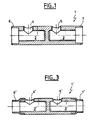
- Figure 1 is a longitudinal sectional view of a connector according to the invention according to a first embodiment.
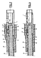
- Figure 2 is a partial view in longitudinal section of a connection of two cables according to the invention according to this first mode of production.
- Figure 3 is a longitudinal sectional view of a connector according to the invention according to a second embodiment.
- Figure 4 is a partial view in longitudinal section of a connection according to the invention according to this second embodiment.
- the following description relates to the connection of two cables medium voltage over 10 kV. Although single-conductor cables be described, the invention also applies to multi-conductor cables.
- FIG. 1 therefore represents a connector according to the invention according to a first embodiment.
- This connector 1 of conductors is made up in a known manner of self of a cylindrical body pierced with two longitudinal cylindrical orifices 2, 3 said contacts and intended to receive the ends of conductors, once bare cable ends.
- longitudinal holes 2, 3 open respectively threaded bores 4, 5 intended to receive each a locking screw ensuring the electrical contact of each driver.
- the connector 1 has at each of its ends a extension means integral with connector 1 consisting of a flange rigid annular 6, 7 disposed at the periphery of the connector, plus precisely of external diameter equal to that of the connector and of diameter internal superior to that of the insulating jacket of the largest cable of the range covered.
- the covering means covers the insulating envelope 11 over a length greater than 10 mm and preferably between 10 and 20 mm.
- the flange 6, 7 is of a length of about 15 mm.
- the flange 6 is preferably an integral part of the connector 1 and its free end is rounded.
- Figure 2 partially shows a connection of two cables with the connector shown in Figure 1. This connection being symmetrical about a vertical axis seen in the figure, only one cable connected is shown.
- the cable is stripped at its end and the conductor 10 is fitted in contact 2, the insulating jacket 11 of the cable coming near the end of the contact 2.
- the semiconductor coating 12 covering the envelope 11 is removed over a greater length in order to be covered by the heat-shrinkable or cold-insulating sheath 20, itself coated with a semiconductor layer 21.
- the screws 8 of the connector are screwed to clamp the conductor 10 against the wall of the connector and the space above each screw 8 is filled with conductive sealant or a cover of semiconductor material 9.
- the retractable sheath 20 is placed places and fits the external contour of connector 1 and the cable.
- the flange 6 therefore projects above the insulating envelope 11 of the cable and screen form in this transition zone.
- the sheath 20 is applied thereon leaving a relatively large space between on the one hand the flange 6 and the insulating jacket 11 of the cable and on the other hand between the sheath 20 and this envelope 11.
- This space is easily filled with insulating mastic 13 which also fills the interfaces between the sheath 20 and the connector 1 and the insulating jacket 20 of the cable, the putty expelling air and ensuring a good electrical connection.
- This layer of insulating putty is brought by the insulating sheath during its retraction.
- FIG. 3 represents a connector according to the invention according to a second embodiment.
- This connector 1 ′ of conductors is made up in a known manner of self of a cylindrical body pierced by two longitudinal cylindrical orifices 2 ', 3' once the cable ends are stripped. In these holes longitudinal 2 ', 3' respectively open threaded bores 4 ', 5' intended to each receive a locking screw ensuring electrical contact of each driver.
- the connector 1 ' has at each of its ends a means extension integral with the connector 1 'consisting of a flexible skirt 6', 7 ' of semiconductor rubber attached to the periphery of the connector, plus precisely with an external diameter smaller than that of the connector and internal diameter adapted to the diameter of the smallest insulating jacket covered range cable, the end of this skirt being rounded.
- the skirt 6 ′, 7 ′ forms a extension of a length of about 15 mm.
- Figure 4 partially shows a connection of two cables with the connector shown in Figure 3. This connection being symmetrical about a vertical axis seen in the figure, only one cable connected is shown.
- the cable is stripped at its end and the conductor 10 is fitted in contact 2 ', the insulating jacket 11 of the cable coming near the end of the connector 1 '.
- the semiconductor coating 12 covering the sheath 11 is removed over a greater length in order to be covered by the heat-shrinkable or cold-insulating sheath 20, itself coated with a semiconductor layer 21.
- the screws 8 'of the connector are screwed to clamp the conductor 10 against the wall of the connector and the space above each 8 'screw is filled with conductive sealant or a cover in 9 'semiconductor material.
- the retractable sheath 20 is put in places and fits the external contour of the 1 'connector and the cable, providing a layer of insulating putty 13 which fills the irregularities of remaining area.
- the skirt 6 ′ therefore projects from the insulating envelope 11 of the cable, intimately covers this envelope 11 and forms a screen thanks to its flexibility in this transition zone.
- the internal diameter of the skirt 6 ' is chosen to adapt to the smallest diameter of the cable insulating jacket to be connected by connector 1 '.
- the interfaces between the sheath 20 and the connector 1 and the casing insulation 20 of the cable are filled with insulating mastic 13.
Landscapes
- Cable Accessories (AREA)
- Coupling Device And Connection With Printed Circuit (AREA)
- Multi-Conductor Connections (AREA)
- Connector Housings Or Holding Contact Members (AREA)
- Processing Of Terminals (AREA)
Abstract
Selon l'invention, ledit moyen de recouvrement couvre l'enveloppe isolante (11) sur une longueur supérieure à 10 mm.
Description
Claims (10)
- Connecteur de deux câbles d'énergie électrique de moyenne tension, comportant chacun au moins un conducteur (10) entouré d'une enveloppe isolante (11), connecteur (1, 1') comportant des contacts vissés tubulaires (2, 3, 2', 3') et destiné à connecter ensemble les extrémités mises à nu desdits conducteurs engagées dans lesdits contacts et maintenues au moyen de vis (8, 8'), connecteur comportant à au moins une de ses extrémités un moyen de prolongement (6, 7, 6', 7') solidaire du connecteur et destiné à couvrir une partie de l'enveloppe isolante (11) du câble, caractérisé en ce que ledit moyen de recouvrement couvre l'enveloppe isolante (11) sur une longueur supérieure à 10 mm.
- Connecteur selon la revendication 1, caractérisé en ce que ledit moyen de recouvrement couvre l'enveloppe isolante (11) sur une longueur comprise entre 10 et 20 mm.
- Connecteur selon la revendication 1 ou 2, caractérisé en ce que ledit moyen de prolongement (6, 7, 6', 7') comporte une extrémité libre arrondie.
- Connecteur selon l'une des revendications précédentes, caractérisé en ce que ledit moyen de prolongement est constitué d'une bride annulaire rigide (6) disposée à la périphérie du connecteur (1).
- Connecteur selon la revendication 4, caractérisé en ce que ladite bride (6) est une partie intégrante dudit connecteur (1).
- Connecteur selon l'une des revendications 1 à 3, caractérisé en ce que ledit moyen de prolongement est constitué d'une jupe flexible (6') de caoutchouc semi-conducteur fixée à la périphérie du connecteur (1 ').
- Connexion de deux câbles d'énergie électrique de moyenne tension, comportant chacun au moins un conducteur (10) entouré d'une enveloppe isolante (11), connexion comportant un connecteur (1, 1') selon l'une des revendications précédentes et une gaine isolante (20) adaptée pour couvrir intimement au moins ledit connecteur.
- Connexion selon la revendication 7, caractérisé en ce que l'espace entre ledit connecteur (1, 1') et l'enveloppe isolante (11) du câble correspondant est rempli d'une couche de mastic isolant (13).
- Connexion selon la revendication 7 ou 8, caractérisée en ce que l'espace entre la couche de mastic isolant (13) et chaque vis (8, 8') est rempli de mastic conducteur.
- Connexion selon la revendication 7 ou 8, caractérisée en ce que l'espace entre la couche de mastic isolant (13) et chaque vis (8, 8') est rempli d'un capot (9, 9') en matériau semi-conducteur.
Applications Claiming Priority (2)
| Application Number | Priority Date | Filing Date | Title |
|---|---|---|---|
| FR0211207 | 2002-08-30 | ||
| FR0211207A FR2844101B1 (fr) | 2002-08-30 | 2002-08-30 | Connecteur de deux cables d'energie electrique et connexion comportant un tel connecteur |
Publications (2)
| Publication Number | Publication Date |
|---|---|
| EP1394900A1 true EP1394900A1 (fr) | 2004-03-03 |
| EP1394900B1 EP1394900B1 (fr) | 2005-12-28 |
Family
ID=31198353
Family Applications (1)
| Application Number | Title | Priority Date | Filing Date |
|---|---|---|---|
| EP03300099A Expired - Lifetime EP1394900B1 (fr) | 2002-08-30 | 2003-08-28 | Connecteur de deux câbles d'énergie électrique et connexion comportant un tel connecteur |
Country Status (6)
| Country | Link |
|---|---|
| US (1) | US6997758B2 (fr) |
| EP (1) | EP1394900B1 (fr) |
| AT (1) | ATE314742T1 (fr) |
| DE (1) | DE60302953T2 (fr) |
| ES (1) | ES2255662T3 (fr) |
| FR (1) | FR2844101B1 (fr) |
Cited By (1)
| Publication number | Priority date | Publication date | Assignee | Title |
|---|---|---|---|---|
| WO2010097309A1 (fr) * | 2009-02-25 | 2010-09-02 | Nexans | Dispositif de connexion de deux conducteurs électriques |
Families Citing this family (11)
| Publication number | Priority date | Publication date | Assignee | Title |
|---|---|---|---|---|
| JP5075488B2 (ja) * | 2007-06-06 | 2012-11-21 | 矢崎総業株式会社 | コネクタ |
| EP2683034B1 (fr) * | 2012-07-02 | 2015-05-06 | Nexans | Procédé de connexion conductrice d'électricité du conducteur électrique de deux câbles de haute tension |
| GB2521447A (en) | 2013-12-20 | 2015-06-24 | Technip France | A PIP trace heating connection assembly |
| EP3001523B1 (fr) * | 2014-09-24 | 2018-11-14 | Tyco Electronics Raychem GmbH | Connecteur électrique pour connexion de bout en bout |
| CN105720394A (zh) * | 2014-12-02 | 2016-06-29 | 苏珊·阿普莎加 | 连接系统 |
| ES2690979T3 (es) * | 2015-12-23 | 2018-11-23 | Nkt Hv Cables Gmbh | Un dispositivo de unión de cables de alimentación de alta tensión y un cable de alimentación que comprende el mismo |
| CN106207519A (zh) * | 2016-06-24 | 2016-12-07 | 苏州华本机电有限公司 | 一种侧连接线缆机构 |
| DE202017004743U1 (de) * | 2017-09-11 | 2018-12-12 | Woertz Engineering Ag | Kabelverbinder und Kabelabschluss |
| US11276946B2 (en) * | 2019-03-21 | 2022-03-15 | TE Connectivity Services Gmbh | Cable connector system and a method of connecting electrical cables |
| PL237953B1 (pl) * | 2019-05-15 | 2021-06-14 | Erko Spolka Z Ograniczona Odpowiedzialnoscia Spolka Komandytowa | Złączka z gwintami rozmieszczonymi pod śrubę zrywalną z elementem dociskowym, zespół połączeń kabli elektroenergetycznych oraz sposób łączenia zespołu połączeń elektrycznych |
| US11424608B2 (en) | 2020-02-18 | 2022-08-23 | Nvent Services Gmbh | Devices and methods for electrical cable splices |
Citations (4)
| Publication number | Priority date | Publication date | Assignee | Title |
|---|---|---|---|---|
| CH256320A (de) * | 1946-04-18 | 1948-08-15 | Aluminium Ind Ag | Verfahren zur Verbindung von Organen, von denen mindestens eines ein Drahtseil ist, insbesondere von Freileitungsseilen, welches Drahtseil Drähte aus Aluminium oder Aluminiumlegierungen enthält. |
| DE2740232A1 (de) * | 1977-09-07 | 1979-03-15 | Pfisterer Elektrotech Karl | Verbindungsmuffe |
| EP0698942A1 (fr) * | 1994-08-26 | 1996-02-28 | ARCUS ELEKROTECHNIK Alois Schiffmann GmbH | Connecteur à vis pour câble, notamment pour manchons de jonction à moyenne tension |
| EP1206024A1 (fr) * | 2000-11-10 | 2002-05-15 | Nexans | Jonction de câbles utilisant un ensemble tubulaire semi-conducteur et procédé d'obtention d'un connecteur à blindage lisse |
Family Cites Families (4)
| Publication number | Priority date | Publication date | Assignee | Title |
|---|---|---|---|---|
| US2901725A (en) * | 1954-12-13 | 1959-08-25 | Fargo Mfg Co Inc | Line splice clamp |
| US4077881A (en) | 1976-07-08 | 1978-03-07 | The Lummus Company | Separation of insoluble material from coal liquefaction product by gravity settling |
| US5630735A (en) * | 1995-07-07 | 1997-05-20 | Eckert; John C. | Electrical connector |
| US6325678B1 (en) * | 2000-08-22 | 2001-12-04 | Electric Motion Company, Inc. | Electrical clamp connector |
-
2002
- 2002-08-30 FR FR0211207A patent/FR2844101B1/fr not_active Expired - Fee Related
-
2003
- 2003-08-27 US US10/650,483 patent/US6997758B2/en not_active Expired - Fee Related
- 2003-08-28 EP EP03300099A patent/EP1394900B1/fr not_active Expired - Lifetime
- 2003-08-28 AT AT03300099T patent/ATE314742T1/de not_active IP Right Cessation
- 2003-08-28 DE DE60302953T patent/DE60302953T2/de not_active Expired - Lifetime
- 2003-08-28 ES ES03300099T patent/ES2255662T3/es not_active Expired - Lifetime
Patent Citations (4)
| Publication number | Priority date | Publication date | Assignee | Title |
|---|---|---|---|---|
| CH256320A (de) * | 1946-04-18 | 1948-08-15 | Aluminium Ind Ag | Verfahren zur Verbindung von Organen, von denen mindestens eines ein Drahtseil ist, insbesondere von Freileitungsseilen, welches Drahtseil Drähte aus Aluminium oder Aluminiumlegierungen enthält. |
| DE2740232A1 (de) * | 1977-09-07 | 1979-03-15 | Pfisterer Elektrotech Karl | Verbindungsmuffe |
| EP0698942A1 (fr) * | 1994-08-26 | 1996-02-28 | ARCUS ELEKROTECHNIK Alois Schiffmann GmbH | Connecteur à vis pour câble, notamment pour manchons de jonction à moyenne tension |
| EP1206024A1 (fr) * | 2000-11-10 | 2002-05-15 | Nexans | Jonction de câbles utilisant un ensemble tubulaire semi-conducteur et procédé d'obtention d'un connecteur à blindage lisse |
Cited By (2)
| Publication number | Priority date | Publication date | Assignee | Title |
|---|---|---|---|---|
| WO2010097309A1 (fr) * | 2009-02-25 | 2010-09-02 | Nexans | Dispositif de connexion de deux conducteurs électriques |
| EP2226899A1 (fr) * | 2009-02-25 | 2010-09-08 | Nexans | Dispositif de liaison de deux conducteurs électriques |
Also Published As
| Publication number | Publication date |
|---|---|
| FR2844101A1 (fr) | 2004-03-05 |
| DE60302953T2 (de) | 2006-09-21 |
| FR2844101B1 (fr) | 2004-10-22 |
| DE60302953D1 (de) | 2006-02-02 |
| US20040102081A1 (en) | 2004-05-27 |
| EP1394900B1 (fr) | 2005-12-28 |
| US6997758B2 (en) | 2006-02-14 |
| ES2255662T3 (es) | 2006-07-01 |
| ATE314742T1 (de) | 2006-01-15 |
Similar Documents
| Publication | Publication Date | Title |
|---|---|---|
| EP0504035B1 (fr) | Dispositif de raccordement pour un ou deux câbles électriques, et procédé pour monter ce dispositif à l'extrémité du ou des câbles | |
| EP1394900B1 (fr) | Connecteur de deux câbles d'énergie électrique et connexion comportant un tel connecteur | |
| EP2333801B1 (fr) | Dispositif de raccordement électrique d'une barre appartenant à un jeu de barres à une traversée électrique appartenant à l'enveloppe isolante d'un appareil électrique de coupure | |
| EP0595708B1 (fr) | Dispositif anti-retrait d'isolation, pour câble de puissance à isolation synthétique | |
| EP0669677B1 (fr) | Dispositif de connexion électrique pour écrans de câbles conducteurs, et procédé pour sa mise en oeuvre | |
| EP0549942B1 (fr) | Jonction de câbles électriques, ensemble prémonté de jonction et procédé de mise en oeuvre | |
| EP4454084A1 (fr) | Terminaison d'un câble de transport électrique à haute ou très haute tension et procédé de préparation d'une terminaison d?une extrémité de câble | |
| FR3028677A1 (fr) | Assemblage d'un ensemble de raccordement electrique | |
| EP2403086A1 (fr) | Dispositif de raccordement électrique d'un conducteur tel celui d'une traverse électrique appartenant à l'enveloppe isolante d'un appareil électrique de coupure à un conducteur tel un câble. | |
| FR2599431A1 (fr) | Bobine electromagnetique et dispositif d'allumage pour moteur a combustion interne comportant une telle bobine. | |
| EP0683556B1 (fr) | Pièce de liaison électrique d'un manchon protecteur avec une extrémité d'un écran semi-conducteur d'un câble électrique | |
| FR2732522A1 (fr) | Dispositif d'isolement pour une extremite de cable | |
| EP0278844A1 (fr) | Câble électrique, notamment isolé au papier imprégné, à l'extrémité duquel est rapporté un dispositif de raccordement | |
| FR2741484A1 (fr) | Piece de raccordement electrique | |
| EP1037311B1 (fr) | Dispositif d'étanchéité d'une connexion de tresse plate | |
| FR2599194A1 (fr) | Manchon d'isolation pour extremite unipolaire de conducteur electrique | |
| CA2238260C (fr) | Piece de raccordement electrique | |
| EP0458237B1 (fr) | Connecteur de câble coaxial | |
| CA1296400C (fr) | Cable electrique, notamment isole au papier impregne, a l'extremite duquel est rapporte un dispositif de raccordement | |
| FR2760146A1 (fr) | Manchon d'etancheite et de protection pour une extremite de cable electrique | |
| FR2586865A1 (fr) | Cosse de raccordement electrique, notamment pour des installations exterieures. | |
| FR2488068A2 (fr) | Perfectionnements apportes aux connecteurs electriques presentant une interruption d'ecran | |
| EP2819251A1 (fr) | Dispositif d'extrémité pour câble électrique | |
| BE623125A (fr) | ||
| CH465690A (fr) | Raccord à fiche pour conducteurs électriques |
Legal Events
| Date | Code | Title | Description |
|---|---|---|---|
| PUAI | Public reference made under article 153(3) epc to a published international application that has entered the european phase |
Free format text: ORIGINAL CODE: 0009012 |
|
| AK | Designated contracting states |
Kind code of ref document: A1 Designated state(s): AT BE BG CH CY CZ DE DK EE ES FI FR GB GR HU IE IT LI LU MC NL PT RO SE SI SK TR |
|
| AX | Request for extension of the european patent |
Extension state: AL LT LV MK |
|
| 17P | Request for examination filed |
Effective date: 20040903 |
|
| AKX | Designation fees paid |
Designated state(s): AT BE BG CH CY CZ DE DK EE ES FI FR GB GR HU IE IT LI LU MC NL PT RO SE SI SK TR |
|
| GRAP | Despatch of communication of intention to grant a patent |
Free format text: ORIGINAL CODE: EPIDOSNIGR1 |
|
| GRAS | Grant fee paid |
Free format text: ORIGINAL CODE: EPIDOSNIGR3 |
|
| GRAA | (expected) grant |
Free format text: ORIGINAL CODE: 0009210 |
|
| AK | Designated contracting states |
Kind code of ref document: B1 Designated state(s): AT BE BG CH CY CZ DE DK EE ES FI FR GB GR HU IE IT LI LU MC NL PT RO SE SI SK TR |
|
| PG25 | Lapsed in a contracting state [announced via postgrant information from national office to epo] |
Ref country code: RO Free format text: LAPSE BECAUSE OF FAILURE TO SUBMIT A TRANSLATION OF THE DESCRIPTION OR TO PAY THE FEE WITHIN THE PRESCRIBED TIME-LIMIT Effective date: 20051228 Ref country code: AT Free format text: LAPSE BECAUSE OF FAILURE TO SUBMIT A TRANSLATION OF THE DESCRIPTION OR TO PAY THE FEE WITHIN THE PRESCRIBED TIME-LIMIT Effective date: 20051228 Ref country code: IE Free format text: LAPSE BECAUSE OF FAILURE TO SUBMIT A TRANSLATION OF THE DESCRIPTION OR TO PAY THE FEE WITHIN THE PRESCRIBED TIME-LIMIT Effective date: 20051228 Ref country code: NL Free format text: LAPSE BECAUSE OF FAILURE TO SUBMIT A TRANSLATION OF THE DESCRIPTION OR TO PAY THE FEE WITHIN THE PRESCRIBED TIME-LIMIT Effective date: 20051228 Ref country code: SI Free format text: LAPSE BECAUSE OF FAILURE TO SUBMIT A TRANSLATION OF THE DESCRIPTION OR TO PAY THE FEE WITHIN THE PRESCRIBED TIME-LIMIT Effective date: 20051228 Ref country code: FI Free format text: LAPSE BECAUSE OF FAILURE TO SUBMIT A TRANSLATION OF THE DESCRIPTION OR TO PAY THE FEE WITHIN THE PRESCRIBED TIME-LIMIT Effective date: 20051228 Ref country code: SK Free format text: LAPSE BECAUSE OF FAILURE TO SUBMIT A TRANSLATION OF THE DESCRIPTION OR TO PAY THE FEE WITHIN THE PRESCRIBED TIME-LIMIT Effective date: 20051228 Ref country code: CZ Free format text: LAPSE BECAUSE OF FAILURE TO SUBMIT A TRANSLATION OF THE DESCRIPTION OR TO PAY THE FEE WITHIN THE PRESCRIBED TIME-LIMIT Effective date: 20051228 |
|
| REG | Reference to a national code |
Ref country code: GB Ref legal event code: FG4D Free format text: NOT ENGLISH |
|
| REG | Reference to a national code |
Ref country code: CH Ref legal event code: EP |
|
| REG | Reference to a national code |
Ref country code: IE Ref legal event code: FG4D Free format text: LANGUAGE OF EP DOCUMENT: FRENCH |
|
| REF | Corresponds to: |
Ref document number: 60302953 Country of ref document: DE Date of ref document: 20060202 Kind code of ref document: P |
|
| PG25 | Lapsed in a contracting state [announced via postgrant information from national office to epo] |
Ref country code: SE Free format text: LAPSE BECAUSE OF FAILURE TO SUBMIT A TRANSLATION OF THE DESCRIPTION OR TO PAY THE FEE WITHIN THE PRESCRIBED TIME-LIMIT Effective date: 20060328 Ref country code: BG Free format text: LAPSE BECAUSE OF FAILURE TO SUBMIT A TRANSLATION OF THE DESCRIPTION OR TO PAY THE FEE WITHIN THE PRESCRIBED TIME-LIMIT Effective date: 20060328 Ref country code: GR Free format text: LAPSE BECAUSE OF FAILURE TO SUBMIT A TRANSLATION OF THE DESCRIPTION OR TO PAY THE FEE WITHIN THE PRESCRIBED TIME-LIMIT Effective date: 20060328 Ref country code: DK Free format text: LAPSE BECAUSE OF FAILURE TO SUBMIT A TRANSLATION OF THE DESCRIPTION OR TO PAY THE FEE WITHIN THE PRESCRIBED TIME-LIMIT Effective date: 20060328 |
|
| GBT | Gb: translation of ep patent filed (gb section 77(6)(a)/1977) |
Effective date: 20060315 |
|
| PG25 | Lapsed in a contracting state [announced via postgrant information from national office to epo] |
Ref country code: PT Free format text: LAPSE BECAUSE OF FAILURE TO SUBMIT A TRANSLATION OF THE DESCRIPTION OR TO PAY THE FEE WITHIN THE PRESCRIBED TIME-LIMIT Effective date: 20060529 |
|
| NLV1 | Nl: lapsed or annulled due to failure to fulfill the requirements of art. 29p and 29m of the patents act | ||
| PG25 | Lapsed in a contracting state [announced via postgrant information from national office to epo] |
Ref country code: HU Free format text: LAPSE BECAUSE OF FAILURE TO SUBMIT A TRANSLATION OF THE DESCRIPTION OR TO PAY THE FEE WITHIN THE PRESCRIBED TIME-LIMIT Effective date: 20060629 |
|
| REG | Reference to a national code |
Ref country code: ES Ref legal event code: FG2A Ref document number: 2255662 Country of ref document: ES Kind code of ref document: T3 |
|
| REG | Reference to a national code |
Ref country code: IE Ref legal event code: FD4D |
|
| PG25 | Lapsed in a contracting state [announced via postgrant information from national office to epo] |
Ref country code: MC Free format text: LAPSE BECAUSE OF NON-PAYMENT OF DUE FEES Effective date: 20060831 |
|
| PLBE | No opposition filed within time limit |
Free format text: ORIGINAL CODE: 0009261 |
|
| STAA | Information on the status of an ep patent application or granted ep patent |
Free format text: STATUS: NO OPPOSITION FILED WITHIN TIME LIMIT |
|
| 26N | No opposition filed |
Effective date: 20060929 |
|
| REG | Reference to a national code |
Ref country code: CH Ref legal event code: PL |
|
| PG25 | Lapsed in a contracting state [announced via postgrant information from national office to epo] |
Ref country code: LI Free format text: LAPSE BECAUSE OF NON-PAYMENT OF DUE FEES Effective date: 20070831 Ref country code: CH Free format text: LAPSE BECAUSE OF NON-PAYMENT OF DUE FEES Effective date: 20070831 |
|
| PG25 | Lapsed in a contracting state [announced via postgrant information from national office to epo] |
Ref country code: EE Free format text: LAPSE BECAUSE OF FAILURE TO SUBMIT A TRANSLATION OF THE DESCRIPTION OR TO PAY THE FEE WITHIN THE PRESCRIBED TIME-LIMIT Effective date: 20051228 |
|
| PG25 | Lapsed in a contracting state [announced via postgrant information from national office to epo] |
Ref country code: TR Free format text: LAPSE BECAUSE OF FAILURE TO SUBMIT A TRANSLATION OF THE DESCRIPTION OR TO PAY THE FEE WITHIN THE PRESCRIBED TIME-LIMIT Effective date: 20051228 Ref country code: LU Free format text: LAPSE BECAUSE OF NON-PAYMENT OF DUE FEES Effective date: 20060828 |
|
| PG25 | Lapsed in a contracting state [announced via postgrant information from national office to epo] |
Ref country code: CY Free format text: LAPSE BECAUSE OF FAILURE TO SUBMIT A TRANSLATION OF THE DESCRIPTION OR TO PAY THE FEE WITHIN THE PRESCRIBED TIME-LIMIT Effective date: 20051228 |
|
| PGFP | Annual fee paid to national office [announced via postgrant information from national office to epo] |
Ref country code: ES Payment date: 20100825 Year of fee payment: 8 |
|
| PGFP | Annual fee paid to national office [announced via postgrant information from national office to epo] |
Ref country code: DE Payment date: 20100823 Year of fee payment: 8 Ref country code: FR Payment date: 20100901 Year of fee payment: 8 Ref country code: IT Payment date: 20100823 Year of fee payment: 8 |
|
| PGFP | Annual fee paid to national office [announced via postgrant information from national office to epo] |
Ref country code: GB Payment date: 20100819 Year of fee payment: 8 |
|
| PGFP | Annual fee paid to national office [announced via postgrant information from national office to epo] |
Ref country code: BE Payment date: 20100810 Year of fee payment: 8 |
|
| BERE | Be: lapsed |
Owner name: NEXANS Effective date: 20110831 |
|
| GBPC | Gb: european patent ceased through non-payment of renewal fee |
Effective date: 20110828 |
|
| REG | Reference to a national code |
Ref country code: FR Ref legal event code: ST Effective date: 20120430 |
|
| PG25 | Lapsed in a contracting state [announced via postgrant information from national office to epo] |
Ref country code: BE Free format text: LAPSE BECAUSE OF NON-PAYMENT OF DUE FEES Effective date: 20110831 Ref country code: IT Free format text: LAPSE BECAUSE OF NON-PAYMENT OF DUE FEES Effective date: 20110828 |
|
| REG | Reference to a national code |
Ref country code: DE Ref legal event code: R119 Ref document number: 60302953 Country of ref document: DE Effective date: 20120301 |
|
| PG25 | Lapsed in a contracting state [announced via postgrant information from national office to epo] |
Ref country code: GB Free format text: LAPSE BECAUSE OF NON-PAYMENT OF DUE FEES Effective date: 20110828 Ref country code: FR Free format text: LAPSE BECAUSE OF NON-PAYMENT OF DUE FEES Effective date: 20110831 |
|
| REG | Reference to a national code |
Ref country code: ES Ref legal event code: FD2A Effective date: 20130531 |
|
| PG25 | Lapsed in a contracting state [announced via postgrant information from national office to epo] |
Ref country code: DE Free format text: LAPSE BECAUSE OF NON-PAYMENT OF DUE FEES Effective date: 20120301 |
|
| PG25 | Lapsed in a contracting state [announced via postgrant information from national office to epo] |
Ref country code: ES Free format text: LAPSE BECAUSE OF NON-PAYMENT OF DUE FEES Effective date: 20110829 |