EP1394890A2 - Heat control device for battery - Google Patents
Heat control device for battery Download PDFInfo
- Publication number
- EP1394890A2 EP1394890A2 EP03017483A EP03017483A EP1394890A2 EP 1394890 A2 EP1394890 A2 EP 1394890A2 EP 03017483 A EP03017483 A EP 03017483A EP 03017483 A EP03017483 A EP 03017483A EP 1394890 A2 EP1394890 A2 EP 1394890A2
- Authority
- EP
- European Patent Office
- Prior art keywords
- battery
- heat
- controller
- radiator
- temperature
- Prior art date
- Legal status (The legal status is an assumption and is not a legal conclusion. Google has not performed a legal analysis and makes no representation as to the accuracy of the status listed.)
- Withdrawn
Links
Images


Classifications
-
- G—PHYSICS
- G05—CONTROLLING; REGULATING
- G05D—SYSTEMS FOR CONTROLLING OR REGULATING NON-ELECTRIC VARIABLES
- G05D23/00—Control of temperature
- G05D23/01—Control of temperature without auxiliary power
- G05D23/02—Control of temperature without auxiliary power with sensing element expanding and contracting in response to changes of temperature
- G05D23/08—Control of temperature without auxiliary power with sensing element expanding and contracting in response to changes of temperature with bimetallic element
-
- H—ELECTRICITY
- H01—ELECTRIC ELEMENTS
- H01M—PROCESSES OR MEANS, e.g. BATTERIES, FOR THE DIRECT CONVERSION OF CHEMICAL ENERGY INTO ELECTRICAL ENERGY
- H01M10/00—Secondary cells; Manufacture thereof
- H01M10/60—Heating or cooling; Temperature control
- H01M10/61—Types of temperature control
- H01M10/613—Cooling or keeping cold
-
- H—ELECTRICITY
- H01—ELECTRIC ELEMENTS
- H01M—PROCESSES OR MEANS, e.g. BATTERIES, FOR THE DIRECT CONVERSION OF CHEMICAL ENERGY INTO ELECTRICAL ENERGY
- H01M10/00—Secondary cells; Manufacture thereof
- H01M10/60—Heating or cooling; Temperature control
- H01M10/63—Control systems
- H01M10/635—Control systems based on ambient temperature
-
- H—ELECTRICITY
- H01—ELECTRIC ELEMENTS
- H01M—PROCESSES OR MEANS, e.g. BATTERIES, FOR THE DIRECT CONVERSION OF CHEMICAL ENERGY INTO ELECTRICAL ENERGY
- H01M10/00—Secondary cells; Manufacture thereof
- H01M10/60—Heating or cooling; Temperature control
- H01M10/63—Control systems
- H01M10/637—Control systems characterised by the use of reversible temperature-sensitive devices, e.g. NTC, PTC or bimetal devices; characterised by control of the internal current flowing through the cells, e.g. by switching
-
- H—ELECTRICITY
- H01—ELECTRIC ELEMENTS
- H01M—PROCESSES OR MEANS, e.g. BATTERIES, FOR THE DIRECT CONVERSION OF CHEMICAL ENERGY INTO ELECTRICAL ENERGY
- H01M10/00—Secondary cells; Manufacture thereof
- H01M10/60—Heating or cooling; Temperature control
- H01M10/64—Heating or cooling; Temperature control characterised by the shape of the cells
- H01M10/643—Cylindrical cells
-
- H—ELECTRICITY
- H01—ELECTRIC ELEMENTS
- H01M—PROCESSES OR MEANS, e.g. BATTERIES, FOR THE DIRECT CONVERSION OF CHEMICAL ENERGY INTO ELECTRICAL ENERGY
- H01M10/00—Secondary cells; Manufacture thereof
- H01M10/60—Heating or cooling; Temperature control
- H01M10/64—Heating or cooling; Temperature control characterised by the shape of the cells
- H01M10/647—Prismatic or flat cells, e.g. pouch cells
-
- H—ELECTRICITY
- H01—ELECTRIC ELEMENTS
- H01M—PROCESSES OR MEANS, e.g. BATTERIES, FOR THE DIRECT CONVERSION OF CHEMICAL ENERGY INTO ELECTRICAL ENERGY
- H01M10/00—Secondary cells; Manufacture thereof
- H01M10/60—Heating or cooling; Temperature control
- H01M10/65—Means for temperature control structurally associated with the cells
- H01M10/655—Solid structures for heat exchange or heat conduction
- H01M10/6551—Surfaces specially adapted for heat dissipation or radiation, e.g. fins or coatings
-
- H—ELECTRICITY
- H01—ELECTRIC ELEMENTS
- H01M—PROCESSES OR MEANS, e.g. BATTERIES, FOR THE DIRECT CONVERSION OF CHEMICAL ENERGY INTO ELECTRICAL ENERGY
- H01M10/00—Secondary cells; Manufacture thereof
- H01M10/60—Heating or cooling; Temperature control
- H01M10/66—Heat-exchange relationships between the cells and other systems, e.g. central heating systems or fuel cells
- H01M10/663—Heat-exchange relationships between the cells and other systems, e.g. central heating systems or fuel cells the system being an air-conditioner or an engine
-
- H—ELECTRICITY
- H01—ELECTRIC ELEMENTS
- H01M—PROCESSES OR MEANS, e.g. BATTERIES, FOR THE DIRECT CONVERSION OF CHEMICAL ENERGY INTO ELECTRICAL ENERGY
- H01M10/00—Secondary cells; Manufacture thereof
- H01M10/60—Heating or cooling; Temperature control
- H01M10/66—Heat-exchange relationships between the cells and other systems, e.g. central heating systems or fuel cells
- H01M10/667—Heat-exchange relationships between the cells and other systems, e.g. central heating systems or fuel cells the system being an electronic component, e.g. a CPU, an inverter or a capacitor
-
- F—MECHANICAL ENGINEERING; LIGHTING; HEATING; WEAPONS; BLASTING
- F28—HEAT EXCHANGE IN GENERAL
- F28F—DETAILS OF HEAT-EXCHANGE AND HEAT-TRANSFER APPARATUS, OF GENERAL APPLICATION
- F28F13/00—Arrangements for modifying heat-transfer, e.g. increasing, decreasing
- F28F2013/005—Thermal joints
- F28F2013/008—Variable conductance materials; Thermal switches
-
- Y—GENERAL TAGGING OF NEW TECHNOLOGICAL DEVELOPMENTS; GENERAL TAGGING OF CROSS-SECTIONAL TECHNOLOGIES SPANNING OVER SEVERAL SECTIONS OF THE IPC; TECHNICAL SUBJECTS COVERED BY FORMER USPC CROSS-REFERENCE ART COLLECTIONS [XRACs] AND DIGESTS
- Y02—TECHNOLOGIES OR APPLICATIONS FOR MITIGATION OR ADAPTATION AGAINST CLIMATE CHANGE
- Y02E—REDUCTION OF GREENHOUSE GAS [GHG] EMISSIONS, RELATED TO ENERGY GENERATION, TRANSMISSION OR DISTRIBUTION
- Y02E60/00—Enabling technologies; Technologies with a potential or indirect contribution to GHG emissions mitigation
- Y02E60/10—Energy storage using batteries
Definitions
- the present invention relates to a heat control device for a battery that controls dissipation of heat generated from the battery in the wake of a charging and discharging process.
- a secondary battery such as an alkaline storage battery, a lead acid battery, and a lithium-ion secondary battery
- a secondary battery such as an alkaline storage battery, a lead acid battery, and a lithium-ion secondary battery
- a lithium-ion secondary battery and a nickel-metal-hydride (NiMH) battery
- a demanded condition increases heat generation from a battery, which often invites deterioration in the electrolyte of the battery. This can shorten the lifetime of the battery.
- the electrolyte of a lithium-ion secondary battery and an NiMH battery is deteriorated at the temperatures beyond 40 °C, which causes deterioration of the batteries. Therefore, the battery should be heat-dissipated so as not to reach the temperature.
- FIG. 14 is a perspective view of the radiator introduced in the publication.
- battery container 101 has radiation fins 102 on the surfaces of the container in the widthwise direction.
- Such structured fins 102 deprive a battery of heat even under low-temperature conditions with no need for heat dissipation.
- the battery therefore cannot increase the temperature by self-heating, accordingly, internal resistance of the battery increases, which extremely degrades power output characteristics of the battery.
- Japanese Patent Non-examined Publication No. H9-298070 introduces an air-conditioning mechanism dedicated for controlling battery temperature. According to the structure, however, it becomes necessary for an extra space for the air-conditioning mechanism, other than that for batteries. The structure is not suitable, due to its poor mountability and high production cost, for compact electronic equipment.
- the heat control device for a battery of the present invention contains i) a radiator for dissipating heat from a battery generated through the charging and discharging process; and ii) a heat controller that transforms its shape with the application of the heat.
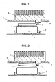
- Figs. 1 and 2 show partially sectional views of a structure of a heat control device for a battery in accordance with the first exemplary embodiment of the present invention.
- the heat control device of the present invention contains i) radiator 5; ii) heat-conducting plate 4 making contact with battery 1 that generates heat due to charging and discharging; and iii) heat controller 6 that connects between plate 4 and radiator 5.
- Battery 1 is held in the interior of equipment by battery holder 2. Fixed to outer wall 3 of equipment, radiator 5 is exposed to the outside of the equipment.
- Heat controller 6 is a heat-sensitive movable section having a bimetallic structure.
- a bimetallic structure is formed such that two metal thin plates having different thermal coefficients of expansion are bonded together; the structure transforms its shape in response to changes in temperature.
- material with low thermal expansion an alloy of nickel and iron is employed; on the other hand, as material with high thermal expansion, copper, nickel, and an alloy of copper and zinc are employed.
- heat-conducting plate 4 contacts, through the expansion of heat controller 6, with battery 1 when the environmental temperature reaches approx. 20 °C. That is, plate 4 maintains contact with battery 1 as long as heat controller 6 keeps temperatures exceeding 20 °C.
- the temperature of controller 6 gets lower than 20 °C transformed heat controller 6 breaks off the contact between heat-conducting plate 4 and battery 1.
- heat-conducting plate 4 is made of a material having good thermal conduction.
- Battery 1 contains six-in-series prismatic NiMH batteries (not shown) with dimensions 96 mm ⁇ 44 mm ⁇ 18 mm. Battery 1 has a capacity of 6.5 Ah. Battery 1 is held in the interior (not shown) of the electronic equipment by battery holder 2.
- Heat generated through a battery-charging and discharging process increases the temperature of battery 1. Accordingly, heated-up air in the equipment raises the temperature of heat controller 6.
- Heated controller 6 expands because of its bimetallic structure.
- heat-conducting plate 4 contacts with the surface of battery 1, as shown in Fig. 1, establishing thermal connection between battery 1 and radiator 5.
- radiator 5 absorbs the heat of battery 1, via heat-conducting plate 4 and heat controller 6, and dissipates the heat into air. This protects battery 1 from anomalous overheating.
- controller 6 when the temperature of controller 6 stays below 20 °C in spite of increased temperature of battery 1 through the charging and discharging process, controller 6 stays in a bend shape, as shown in Fig.2; heat-conducting plate 4 has no contact with battery 1.
- controller 6 bends its shape, allowing heat-conducting sheet 24 to go away from battery 1. That is, radiator 5 is thermally separated from battery 1, thereby protecting battery 1 from over-dissipation. Heat controller 6 thus protects the battery from degradation in output power characteristics.
- Table 1 shows data sets on voltage and surface temperature of batteries. The measurements are carried out so as to compare between i) a battery having the heat control device introduced in the embodiment, ii) a battery having a conventional radiator shown as prior-art example 1 in Fig. 14, and iii) a battery with no radiator.
- 10th discharging measure the minimum value of battery voltage and the temperature of the surface of the battery.
- Bimetallic heat controller 6 has a temperature of at least the environmental temperature in each measurement.
- the temperatures of the battery with no radiator soar up to 51.0 °C and 42.0 °C, respectively.
- the temperature can be kept below 40 °C by the control of bimetallic heat controller 6.
- the structure of the embodiment can thus suppress a rise in the battery temperature in the wake of the charging and discharging process, protecting the battery from being deteriorated.
- the evaluation under the environmental temperature of -5 °C shows that the surface temperature of the battery of prior-art example 1 drops down to -4.3 °C.
- battery container 101 and radiation fins 102 have thermal contact at all times. Therefore, the battery is always dissipating the heat into the outside, without the battery warmed by self-heating.
- the voltage of the battery of prior-art example 1 is extremely lowered to 4.2V.
- heat controller 6 breaks off the thermal contact between battery 1 and radiator 5, so that heat of the battery is no longer dissipated outside the equipment. The battery can thus maintain the temperature by self-heating, which suppresses undesired drop in voltage of the battery.
- bimetallic heat controller 6 can control thermal connection between battery 1 and radiator 5, whereby heat controller 6 protects the battery from overheat, then performance degradation of the battery can be suppressed. Furthermore, in low-temperature ranges, the battery can maintain a proper temperature by self-heating, which protects the battery from degradation in output power characteristics.
- heat conducting plate 4 makes contact with battery 1 when the battery has temperatures in excess of a specified degree
- a side of battery 1 and a part of heat-conducting plate 4 that faces to the side of battery 1 should preferably be flat so as to increase a contact area for effective heat conduction. Forming flat portions on two surfaces facing each other facilitates the control of heat controller 6 - thermal connection can be quickly established or broken off through the increased area.
- the embodiment introduces a structure in which battery 1 contains 6-in-series prismatic NiMH batteries therein, however, the structure of battery 1 is not limited thereto; a structure having a single prismatic NiMH battery, a structure having one or more prismatic lithium-ion secondary battery, or having one or more lead acid battery can provide the same effect. Furthermore, a fuel battery is also applicable.
- Battery 1 may be formed of at least one cylindrical battery. In this case, the cylindrical battery should preferably be housed in a prismatic case, or as is the structure that will be described later in the second exemplary embodiment, the lower surface of radiator 5 should be curved along the cylindrical shape of the battery to increase the area for effective heat conduction.
- heat conduction can be easily established in a direction of the encircling axis of the cylindrical battery than in a radial direction of the battery. Also in the case of similarly structured prismatic battery, heat is easily transferred in a direction of the encircling axis than in a widthwise direction.
- the structure in which heat-conducting plate 4 contacts with a widthwise cross-section of the encircling axis of the battery, as shown in Fig. 3 should be preferable.
- a fuel battery has a structure in the form of a plurality of cells being stacked.
- heat-conducting plate 4 should preferably be designed so as to contact with a side surface of the stacked structure for effective heat conduction.
- an insulating film is disposed on the surface of heat-conducting plate 4 with which the fuel cell contacts.
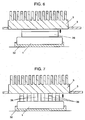
- Figs. 4 and 5 show partially sectional views of a structure of a heat control device for a battery in accordance with the second exemplary embodiment.
- the heat control device of the embodiment contains radiator 5 and heat controller 26 that connects between radiator 5 and outer wall 3 of the equipment.
- Radiator 5 is disposed through outer wall 3 so as to be partially exposed to the outside of the equipment.
- the surface facing to battery 1 is curved so as to fit with the surface of the battery.
- Heat-conducting sheet 24 is attached to the curved surface of radiator 5.
- Heat-conducting sheet 24 contains material in which, for example, i) highly oriented graphite having a close-to-monocrystal structure, which is formed by processing polymer film through heat decomposition so as to have a graphite structure; ii) thermal conductive silicon rubber, or iii) acrylic rubber as a major composition, and to which aluminum or carbon graphite material is combined.
- Radiator 5 is thermally connected to battery 1 via heat-conducting sheet 24 to dissipate heat, which is generated through the charging and discharging process, into the outside of the equipment.
- heat controller 26 also has a bimetallic structure so as to expand with the application of heat. When heated beyond 20 °C, controller 26 moves radiator 5 to battery 1 as shown in Fig. 4, making thermal contact between battery 1 and radiator 5 through heat-conducting sheet 24. When the temperature gets lower than 20 °C, controller 26 bends its shape into "J" as shown in Fig. 5, so that radiator 5 goes away from battery 1.
- Battery 1 of the embodiment is formed of two-in-series cylindrical lithium-ion secondary batteries.
- the battery measures 18 mm in diameter and 65 mm in length, and has a capacity of 1200 mAh.
- Battery 1 is fixed within the interior (not shown) of the equipment by battery holder 2. Besides, battery 1 is separated by outer wall 3 of the equipment from the outside.
- bimetallic heat controller 26 When heated, bimetallic heat controller 26 expands, so that radiator 5 comes down toward inside the equipment. When the temperature of controller 26 reaches 20 °C, heat-conducting sheet 24 comes in contact with the surface of battery 1 as shown in Fig. 4, by which thermal connection between battery 1 and radiator 5 is established. In this way, radiator absorbs heat from battery 1 through heat-conducting sheet 24 and dissipates the heat into air, thereby protecting battery 1 from anomalous overheating.
- controller 26 when the temperature of controller 26 stays below 20 °C in spite of increased temperature of battery 1 through the charging and discharging process, bimetallic controller 26 maintains its J shape.
- controller 26 bends its shape into J shape, so that heat-conducting sheet 24 goes away from battery 1.
- Heat-conducting sheet 24 has no contact with battery 1. That is, radiator 5, which stays in place without moving down in the interior of the equipment, has no thermal connection with battery 1, thereby protecting battery 1 from over-dissipation. Heat controller 26 thus protects the battery from degradation in output power characteristics.
- Table 2 shows data sets on voltage and surface temperature of batteries. The measurements are carried out so as to compare between i) a battery having the heat control device introduced in the embodiment, ii) a battery equipped with a conventional radiator shown in Fig. 14 - which is shown as prior-art example 2 in Table 2, and iii) a cylindrical battery with no radiator.
- a battery having the heat control device introduced in the embodiment ii) a battery equipped with a conventional radiator shown in Fig. 14 - which is shown as prior-art example 2 in Table 2, and iii) a cylindrical battery with no radiator.
- two cylindrical lithium-ion secondary batteries each has the same size as that used in the embodiment, are accommodated in battery container 101.
- Bimetallic heat controller 26 has a temperature of at least the environmental temperature in each measurement.
- the temperature can be kept below 40 °C by the control of bimetallic heat controller 26.
- the structure of the embodiment can thus suppress undesired rise in the battery temperature in the wake of the charging and discharging process, protecting the battery from being deteriorated.
- the evaluation at the environmental temperature of -10 °C shows that the surface temperature of the battery in prior-art example 2 drops down to -5.2 °C.
- battery container 101 and radiation fins 102 have thermal contact at all times. Therefore, the battery is always dissipating the heat into the outside. As a result, the voltage of the battery of prior-art example 2 is extremely lowered to 5.2V.
- heat controller 26 breaks off the thermal contact between battery 1 and radiator 5, so that heat of the battery is no longer dissipated outside the equipment. The battery can thus maintain the temperature by self-heating, which suppresses undesired drop in voltage of the battery.
- forming bimetallic heat controller 26 controls the thermal connection between battery 1 and radiator 5. This protects the battery from not only being overheated, but also being deteriorated. Furthermore, in low temperature ranges, the battery can maintain a proper temperature by self-heating, which protects the battery from degradation in output power characteristics.
- the structure of the embodiment employs heat-conducting sheet 24 to obtain an intimate contact between battery 1 and radiator 5, it is not limited thereto; instead of disposing sheet 24, forming the surface of radiator 5 making contact with battery 1 into a proper shape can provide the similar effect.
- Fig. 6 shows a partially sectional view of a structure of a heat control device for a battery of the third exemplary embodiment.
- the heat control device of the embodiment contains radiator 5 and heat controller 36.
- Heat controller 36 is disposed so as to have contact with battery 1 that generates heat through charging and discharging. Fixed to outer wall 3 of equipment, radiator 5 is exposed to the outside of the equipment. Heat controller 36 is disposed between battery 1 and radiator 5. Battery 1 is held in the equipment by battery holder 32.
- the structure of the first exemplary embodiment contains: i) heat-conducting plate 4 making contact with battery 1; and ii) heat controller 6 connecting between plate 4 and radiator 5.
- the structure of the third embodiment has heat controller 36.
- Battery holder 32 is made of an elastic material. For the rest, the structure of the embodiment is the same as that of the first exemplary embodiment.
- Heat controller 36 has a columnar shape and expands by heat generated from battery 1. Controller 36 is made of a thermally conductive material having a high coefficient of linear expansion, for example, should be made of metal such as aluminum, zinc, and lead. The dimension of heat controller 36 is determined so that the expanded structure reaches radiator 5 at a temperature of 20 °C or higher.
- the temperature of battery 1 becomes higher as battery 1 generates heat through the charging and discharging processes.
- Heat controller 36 expands by the heat and reaches radiator 5 when the temperature of controller 36 reaches 20 °C. At this moment, thermal connection between battery 1 and radiator 5 is established. In this way, radiator 5 absorbs heat from battery 1 via heat controller 36 and dissipates the heat into air, thereby protecting battery 1 from anomalous overheating.
- controller 36 when the temperature of controller 36 stays below 20 °C in spite of increased temperature of battery 1 through the charging and discharging process, controller 36 is maintained out-of-contact with radiator 5. As another case, when battery 1 cools off below 20 °C from a temporally rise beyond 20 °C, heat controller 36 contracts and goes away from radiator 5. This breaks off the thermal connection between radiator 5 and battery 1, protecting battery 1 not only from over-dissipation, but also from degradation in output power characteristics.
- Heat controller 36 of the embodiment directly contacts with battery 1. Compared to the structures of the first and second embodiments, heat controller 36 of the embodiment provides a quicker response to heat generated by the charging and discharging process.
- heat controller 36 as a single structure, as shown in Fig. 6.
- battery 1 is not uniformly heated; generally, the middle part of the battery tends to have a higher temperature. Therefore, it is preferable to form a plurality of heat controllers 36, as shown in Fig. 7.
- thermal connection between battery 1 and radiator 5 is quickly established by the heat controllers disposed where temperature easily rises, thereby battery 1 has a uniform temperature. Ensuring a uniform temperature of battery 1 that is formed of a plurality of electric cells also gives a uniform degree of deterioration of the electric cells, thereby effectively suppressing variations in characteristics among the cells.
- battery holder 2 is made of an elastic material.
- the elasticity can relax the stress caused between battery 1 and radiator 5 due to expansion of heated controller 36, when the temperature of heat controller 36 exceeds 20 °C.
- a spring or the like material can be employed at which outer wall 3 of the equipment holds radiator 5.
- a heat-conducting sheet can be disposed at sections having contact with heat controller 36 on the lower surface of radiator 5.
- the heat-conducting sheet can be disposed on the top or bottom surfaces of heat controller 36.
- Table 3 shows data sets on voltage and surface temperature of batteries. The measurements are carried out so as to compare between i) a battery having the heat control device introduced in the embodiment, ii) a battery having a structure introduced in the first embodiment, and iii) a battery with no radiator. The evaluation is carried out at an environmental temperature of 30 °C under the condition and the structure of battery 1 similar to those employed in the first embodiment.
- cell A indicates an outmost cell among six cells connected in series of battery 1 and cell B indicates a cell next to cell A to the middle part of battery 1, cell C indicates a cell next to cell B in the same direction.
- the battery with no radiator has high temperature of 56.0 °C at the middle part of it.
- the battery of the first embodiment is heated as high as 40 °C in the middle part of it.
- the temperature of the battery of the third embodiment is kept below 40 °C even in the middle part. This is because that heat dissipation by mid-positioned heat controllers 36 occurs earlier than outer parts.
- heat controller 36 of the third embodiment because of having direct contact with battery 1, can be sensitive to heat generation in battery 1. The quick response to rise in the temperature can thus keep the average value of the surface temperature lower.
- the structure of the embodiment can suppress rises in the temperature of the battery in the wake of the charging and discharging process more sensitively, protecting the battery from being deteriorated.
- disposing a plurality of heat controllers 36 can minimize degradation in sections easy to be heated therefore easy-to-be deteriorated.
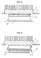
- Fig. 8 shows a partially sectional view of a structure of a heat control device for a battery in accordance with the fourth exemplary embodiment.
- the heat control device of the embodiment contains radiator 5 and heat controller 46.
- Heat controller 46 is disposed so as to have contact with battery 1 that generates heat through charging and discharging. Fixed to outer wall 3 of equipment, radiator 5 is exposed to the outside of the equipment.
- heat controller 36 has a columnar-shaped structure that expands on the application of heat.
- the fourth embodiment employs a bimetallic flat plate formed into a U-shape in section for heat controller 46.
- the structure of the embodiment is the same as that of the third exemplary embodiment.
- heat controller 46 material with a high expansion is used for the inside of the "U” so as to open up the space between the arms of the "U” as controller 46 is heated.
- the dimension of heat controller 46 is determined so that the expanded arm reaches radiator 5 at a temperature of approx. 20 °C. That is, heat controller 46 contacts with battery 1 at a temperature of 20 °C or higher. When the temperature falls below 20 °C, heat controller 46 goes away from battery 1.
- the temperature of battery 1 becomes higher as battery 1 generates heat through the charging and discharging processes. Received the heat, controller 46 expands, whereby the space between the arms of the "U” is opened up, and the surface of the upper arm contacts with radiator 5 when the temperature of controller 46 reaches 20 °C. At this moment, thermal connection between battery 1 and radiator 5 is established. In this way, radiator 5 absorbs heat from battery 1 via heat controller 46 and dissipates the heat into air, thereby protecting battery 1 from anomalous overheating. As heat controller 46 behaves like a spring because of its bimetallic structure, there is no need to employ an elastic material for battery holder 2.
- controller 46 when the temperature of controller 46 stays below 20 °C in spite of increased temperature of battery 1 through the charging and discharging process, controller 46 is maintained out of contact with radiator 5. As another case, when battery 1 cools off below 20 °C from a temporally rise beyond 20 °C, the space between the arms of the "U” becomes narrower, i.e., heat controller 46 goes away from radiator 5. This breaks off the thermal connection between radiator 5 and battery 1, protecting battery 1 from not only over-dissipation but also degradation in output power characteristics. In this way, the structure of the embodiment provides the same effect as is in the structure of the third embodiment.
- heat controller 46 of the embodiment is U-shaped, it is not limited thereto: a structure having more than one bend, such as S-shaped structure, can be employed. Generally J-shaped heat controller 46 also can be used. In this case, a heat-conducting plate is connected to the surface of controller 46 that faces to radiator 5. With the structure, heat is conveyed from battery 1, via heat controller 46 and the heat-conducting plate, to radiator 5, when battery 1 has undesired rise in temperature.
- forming a plurality of heat controllers 46 is applicable to the structure of the fourth embodiment.
- Fig. 9 shows a partially sectional view of a structure of a heat control device for a battery in accordance with the fifth exemplary embodiment.
- the heat control device of the embodiment contains radiator 5 and heat controller 56.
- Heat controller 56 is disposed so as to have contact with battery 1 that generates heat through charging and discharging. Fixed to outer wall 3 of equipment, radiator 5 is exposed to the outside of the equipment. Heat controller 56 of the embodiment is disposed between battery 1 and inner wall 43 of the equipment via battery holder 2.
- Heat controller 56 is a thermally sensitive movable section, which is made of a shape-memory alloy, having a U shape in section.
- a shape-memory alloy has the property of putting a shape back into a preformed shape when the temperature exceeds a certain temperature (i.e., transformation temperature), even if it has been transformed at temperatures lower than the transformation point.
- the shape-memory alloy consists of, for example, an indium-tellurium alloy, or a nickel-titanium alloy.
- Heat controller 56 has a structure having a composition determined so as to have a transformation temperature of 20 °C, and then the structure is formed into a U-shape at a temperature of 20 °C or higher - such structured controller 56 puts its shape into the preformed "U” at a temperature of 20 °C or higher.
- the interval between the "U” becomes smaller in under the weight of battery 1. That is, the dimension of heat controller 56 is determined so that the controller 56 contacts battery 1 with radiator 5 at a temperature of 20 °C or higher, on the other hand, controller 56 keeps radiator 5 away from battery 1 under temperatures lower than 20 °C.
- the structure of the embodiment is the same as that of the third exemplary embodiment.
- the temperature of battery 1 becomes higher as battery 1 generates heat through the charging and discharging processes.
- Heated controller 56 changes its shape into a preformed opened-up "U" when the temperature of controller 56 reaches 20 °C.
- the transformation of controller 56 lifts up battery 1, thereby battery 1 contacts directly with radiator 5.
- radiator 5 absorbs heat from battery 1 and dissipates the heat into air, thereby protecting battery 1 from anomalous overheating.
- shape-memory alloy-made heat controller 56 behaves like a spring, there is no need to employ an elastic material for battery holder 2.
- Controller 56 can thus protect battery 1 from not only over-dissipation but also degradation in output power characteristics.
- battery 1 cools off below 20 °C after the temperature of controller 56 gets higher than 20 °C so thatcontroller 56 changes its shape into aits preformed opened-up "U", the interval between the two arms of the "U” becomes narrower in under the weight of battery 1, allowing battery 1 to go away from radiator 5.
- heat controller 56 of the fifth embodiment directly contacts with battery 1. Therefore, heat controller 56 of the embodiment can be sensitive to a rise in temperature.
- the direct contact between battery 1 and radiator 5 of the fifth embodiment encourages heat conduction.
- Table 4 shows a data set on voltage and surface temperature of a battery having the heat control device of the embodiment. The evaluation is carried out under the condition and the structure of battery 1 similar to those employed in the first embodiment.
- the structure of the embodiment, in which battery 1 has direct contact with radiator 5 can dissipate the heat more effective than that of the first embodiment.
- thermocontrol 56 Although a shape-memory alloy is employed for heat controller 56 in the embodiment, a bimetallic heat controller, like the structure in the fourth embodiment, can provide the same effect.
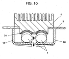
- Fig. 10 shows a partially sectional view of a structure of a heat control device for a battery in accordance with the sixth exemplary embodiment.
- the heat control device of the embodiment contains radiator 5 and heat controller 66.
- Heat controller 66 is disposed so as to have contact with battery 1 that generates heat through charging and discharging. Fixed to outer wall 3 of equipment, radiator 5 is exposed to the outside of the equipment. Radiator 5 is thermally connected, via heat-conducting sheet 24, to battery 1. One end of heat controller 66, which is formed into a L-shape, is fixed to outer wall 3 of the equipment, the other end holds battery 1 in the vicinity thereof.
- Heat controller 66 is a thermally sensitive movable section with a shape of an "L", which is made of a shape-memory alloy.
- Heat controller 66 has a structure having a composition determined so as to have a transformation temperature of 20 °C, and then the structure is formed into an L-shape at a temperature of 20 °C or higher - such structured controller 66 puts its shape into the preformed "L” at a temperature of 20 °C or higher. When the temperature stays below 20 °C, the angle between the "L” is kept larger because of the weight of battery 1.
- the dimension of heat controller 66 is determined so that the controller 66 contacts battery 1 with radiator 5 at a temperature of 20 °C or higher, while the controller keeps radiator 5 away from battery 1 when the temperature is lower than 20 °C.
- the structure of the embodiment is the same as that of the second exemplary embodiment.
- the temperature of battery 1 becomes higher as battery 1 generates heat through the charging and discharging process.
- Heated controller 66 changes its shape into a preformed "L" when the temperature of controller 66 reaches 20 °C.
- the transformation of controller 66 lifts up battery 1, thereby battery 1 contacts with radiator 5.
- thermal connection between battery 1 and radiator 5 is established. In this way, radiator 5 dissipates heat of battery 1 into air, thereby protecting battery 1 from anomalous overheating.
- Controller 66 can thus protect battery 1 from not only over-dissipation but also degradation in output power characteristics.
- battery 1 cools down to lower than 20 °C after the temperature of controller 66 gets higher than 20 °C so that controller 66 changes its shape into its preformed "L", the angle between the two arms of the "L” becomes larger in under the weight of battery 1, thereby battery 1 goes away from radiator 5.
- heat controller 66 of the sixth embodiment directly contacts with battery 1. Therefore, heat controller 66 can be sensitive to a rise in temperature.
- the direct contact between battery 1 and radiator 5 also encourages heat conduction.
- Table 5 shows a data set on voltage and surface temperature of a battery having the heat control device of the embodiment. The evaluation is carried out under the condition and the structure of battery 1 similar to those employed in the second embodiment.
- the structure of the embodiment, in which heat controller 66 has direct contact with battery 1 can be more sensitive to heat generated through the charging and discharging process than the structure of the second embodiment. This works in further suppressing rises in temperature of battery 1.
- thermocontroller 66 Although a shape-memory alloy is employed for heat controller 66 in the embodiment, a bimetallic heat controller, like the structure in the fourth embodiment, can provide the same effect.
- the structure may contain a battery holder therein.
- a protrusion is disposed at one end supporting battery 1 as shown in Fig. 10, or a dent (not shown) is made in the surface on which battery 1 is mounted for supporting the battery.
- Heat controller 66 may also contain a battery holder, as a separate structure, on the surface that bears battery 1.
- Fig. 11 shows a partially sectional view of a structure of a heat control device for a battery in accordance with the seventh exemplary embodiment.
- the heat control device of the embodiment contains radiator 5 and heat controller 76.
- Heat controller 76 is disposed so as to have contact with battery 1 that generates heat through charging and discharging. Fixed to outer wall 3 of equipment, radiator 5 is exposed to the outside of the equipment.
- heat controller 36 is disposed between battery 1 and radiator 5.
- heat controller 76 is disposed between battery 1 and inner wall 73 of the equipment.
- Such structured heat controller 76 also serves as battery holder 2.
- the device of the embodiment has the structure as that of the third embodiment.
- heat controller 76 Like heat controller 36, heat controller 76 also expands by the heat of battery 1. And the dimension of heat controller 76 is determined so that the expanded structure lifts up battery 1 to contact with radiator 5 at a temperature of 20 °C or higher. Unlike heat controller 36, heat controller 76 is not necessarily to be a conductive material like metal; the controller can be made of material having a high coefficient of linear expansion and having no transformation in the temperature range of the charging and discharging process, namely, nylon resin, silicon resin, and the like.
- a spring or the like (not shown) is employed for a section of outer wall 3 that holds radiator 5.
- the elasticity can relax the stress caused between radiator 5, battery 1 and inner wall 73 due to expansion of heated controller 76, when the temperature of heat controller 76 exceeds 20 °C.
- the temperature of battery 1 becomes higher as battery 1 generates heat through the charging and discharging process. Received the heat, controller 76 expands and battery 1 reaches radiator 5 when the temperature of controller 76 reaches 20 °C. At this moment, thermal connection between battery 1 and radiator 5 is established. In this way, the heat of battery 1 is directly transferred to radiator 5 and dissipated into air, so that battery 1 is protected from anomalous overheating.
- controller 76 when the temperature of controller 76 stays below 20 °C in spite of increased temperature of battery 1 through the charging and discharging process, controller 76 is maintained out of contact with radiator 5. As another case, when battery 1 cools off below 20 °C from a temporally rise beyond 20 °C, heat controller 76 contracts and battery 1 goes away from radiator 5. This breaks off the thermal connection between radiator 5 and battery 1, protecting battery 1 from not only over-dissipation but also degradation in output power characteristics. In this way, the structure of the embodiment provides the same effect as that of the fifth embodiment.
- a heat-conducting sheet can be disposed on a section having contact with battery 1 on the lower surface of radiator 5
- heat controller 76 is disposed on inner wall 73 of the equipment; the controller can be disposed on a substrate or the like. In this case, it is preferable that the substrate be fixed to the inner wall via a spring and the like. Such a structure can relax the stress caused between radiator 5 and battery 1 due to expansion of heated controller 76, when the temperature of heat controller 76 exceeds 20 °C.
- Fig. 12 is a perspective view illustrating the heat controller of a heat control device for a battery in accordance with the eighth exemplary embodiment.
- the heat control device of the embodiment differs from the device of the seventh embodiment in employing heat controller 86, instead of heat controller 76. For the rest, the two structures have no difference.
- Heat controller 86 has a structure in which bimetallic material is curled and then formed into a helical shape. The double helix expands by the heat of battery 1. The dimension of heat controller 86 is determined so that the expanded structure contacts battery 1 with radiator 5 at a temperature of 20 °C or higher. This structure provides the same effect as that of the seventh embodiment.
- Heat controller 86 can relax, by its own spring-like shape, the stress caused between radiator 5, battery 1 and inner wall 73 due to expansion of heated controller 86, when the temperature of heat controller 86 exceeds 20 °C.
- Fig. 13 shows a partially sectional view of a structure of a heat control device for a battery in accordance with the ninth exemplary embodiment.
- the heat control device of the embodiment further contains heat source 94 disposed on substrate 93, and heat conductor 95 that establishes thermal connection between heat source 94 and battery 1.
- heat source 94 corresponds to the central processing unit (CPU), or in the case that the equipment is a vehicle, heat source 94 is an engine.
- Heat controller 76 contracts, as the temperature gets lower. Considering the coefficient of linear expansion of heat controller 76, the dimension of heat conductor 95 is determined so as to contact with battery 1 at temperatures of 0 °C or lower.
- Heat conductor 95 can be formed of metal and the like; however, with a view to enhancing intimate contact with battery 1 and heat source 94 and suppressing stress due to thermal expansion, it should preferably be formed of material similar to heat-conducting sheet 24 described in the second embodiment.
- the aforementioned structure behaves similarly to that in the seventh embodiment.
- the temperature of heat controller 76 drops down to 0 °C or lower, heat conductor 95 makes contact with battery 1. This establishes thermal connection between heat source 94 and battery 1, so that heat source 94 increases the temperature of battery 1. The heating-up more effectively protects battery 1 from degradation in output power characteristics than the case in the fourth embodiment.
- Table 6 shows a data set on voltage and surface temperature of a battery having the heat control device of the embodiment.
- a CPU with power consumption of about 60 W is used for heat source 94.
- the evaluation is carried out under the condition and the structure of battery 1 similar to those employed in the second embodiment.
- Environmental temperature 30 °C -10 °C Voltage (V) Surface temperature (°C) Voltage (V) Surface temperature (°C) Battery in embodiment 9 7.2 37.0 6.6 7.0
- heat controller 76 employing heat controller 56 described in the fifth embodiment or heat controller 86 in the eighth embodiment can also provide the same effect.
- the heat controller is supposed to activate the control of thermal connection between the battery and the radiator at a temperature of 20 °C.
- the heat controller may have a temperature range of 10 °C to 20 °C so as to enhance heat dissipation in high temperatures and to protect over-dissipation in low temperatures.
- the structure throughout the embodiments can be employed for various kinds of batteries, as long as the battery generates heat through the charging and discharging process.
- the heat controller should be formed of a material easy to transform by heat, preferably, formed of metal.
- the structure of the embodiments can provide a considerable advantage in the case that the environmental temperature is low, or in the case that the equipment needs intermittent operations of high-power discharging, in particular, such as a compact space-saving electronic device with a low cost.
- thermo connection between the battery and the radiator is governed by the heat controller.
- the shape of the heat controller is not limited to a specific one, as long as the controller can properly control the thermal connection.
- a bimetallic heat controller is introduced in the first, second, and fourth embodiments, and a controller made of shape-memory alloy is explained in the fifth and sixth embodiments, the material is not limited thereto.
- battery 1 is formed of a plurality of cells, it is not limited thereto; battery 1 can be a single cell. In the case that battery 1 is formed of a plurality of cells, the number of the cells and connections (i.e., in-series or parallel) are not limited.
- the heat controller moves the battery.
- a guide section (not shown) should preferably be disposed to place the battery in a right position.
- the heat control device for a battery of the present invention provides a simple structure having a heat controller.
- the device can dissipate heat generated in a battery to outside, protecting the battery from over-heating. As a result, the battery is protected from degradation.
- the device protects the battery from over-dissipation, thereby protecting the battery from degradation in output power characteristics.
- the heat control device provides an effective use of batteries under various environments.
Landscapes
- Engineering & Computer Science (AREA)
- Manufacturing & Machinery (AREA)
- Chemical & Material Sciences (AREA)
- Chemical Kinetics & Catalysis (AREA)
- Electrochemistry (AREA)
- General Chemical & Material Sciences (AREA)
- Automation & Control Theory (AREA)
- Physics & Mathematics (AREA)
- General Physics & Mathematics (AREA)
- Secondary Cells (AREA)
- Battery Mounting, Suspending (AREA)
Abstract
Description
| Environmental temperature | 30 °C | 20 °C | -5 °C | |||
| Voltage (V) | Surface temperature (°C) | Voltage (V) | Surface temperature (°C) | Voltage (V) | Surface temperature (°C) | |
| Battery in | 6.6 | 38.5 | 6.6 | 32.0 | 5.7 | 3.0 |
| Prior-art example 1 | 6.6 | 38.5 | 6.7 | 32.0 | 4.2 | -4.3 |
| Battery with no radiator | 6.7 | 51.0 | 6.3 | 42.0 | 5.8 | 3.1 |
| Environmental temperature | 30 °C | -10 °C | ||
| Voltage (V) | Surface temperature (°C) | Voltage (V) | Surface temperature (°C) | |
| Battery in | 7.2 | 38.0 | 6.3 | 1.4 |
| Prior-art example 2 | 7.2 | 39.0 | 5.2 | -5.2 |
| Battery with no radiator | 7.0 | 52.0 | 6.4 | 0.5 |
| Surface temperature (°C) | Total Voltage (V) | ||||
| Measured location | Cell A | Cell B | Cell C | Average | |
| Battery in | 37.0 | 38.0 | 39.0 | 38.0 | 6.6 |
| Battery in | 37.1 | 38.5 | 39.9 | 38.5 | 6.6 |
| Battery with no radiator | 46.0 | 51.0 | 56.0 | 51.0 | 6.7 |
| Environmental temperature | 30 °C | 20 °C | -5 °C | |||
| Voltage (V) | Surface temperature (°C) | Voltage (V) | Surface temperature (°C) | Voltage (V) | Surface temperature (°C) | |
| Battery in | 6.6 | 37.5 | 6.6 | 30.0 | 5.7 | 3.0 |
| Environmental temperature | 30 °C | -10 °C | ||
| Voltage (V) | Surface temperature (°C) | Voltage (V) | Surface temperature (°C) | |
| Battery in | 7.2 | 37.0 | 6.3 | 1.4 |
| Environmental temperature | 30 °C | -10 °C | ||
| Voltage (V) | Surface temperature (°C) | Voltage (V) | Surface temperature (°C) | |
| Battery in embodiment 9 | 7.2 | 37.0 | 6.6 | 7.0 |
Claims (11)
- A heat control device for a battery comprising:a heat controller that transforms its shape by heat generated in a battery; anda radiator for dissipating the heat from the battery.
- The heat control device for a battery of Claim 1, wherein the heat controller establishes thermal connection between the radiator and the battery at a temperature at least a predetermined first temperature.
- The heat control device for a battery of Claim 1, wherein the heat controller breaks off the thermal connection between the radiator and the battery at a temperature lower than a predetermined first temperature.
- The heat control device for a battery of Claim 2, wherein the heat controller establishes the thermal connection, via the heat controller, between the radiator and the battery.
- The heat control device for a battery of Claim 2, wherein the heat controller physically contacts the radiator to the battery.
- The heat control device for a battery of Claim 2, wherein the heat controller establishes the thermal connection between the radiator and the battery by bending the heat controller itself.
- The heat control device for a battery of Claim 2, wherein the heat controller establishes the thermal connection between the radiator and the battery by expanding the heat controller itself.
- The heat control device for a battery of Claim 1, wherein the heat control device has a plural number of the heat controller.
- The heat control device for a battery of Claim 1 further including:a heat source; anda heat conductor for transferring heat generated from the heat source to the battery at a temperature at most a predetermined second .
- The heat control device for a battery of Claim 1, wherein the controller moves the battery.
- The heat control device for a battery of Claim 1, wherein the controller moves the radiator.
Applications Claiming Priority (2)
| Application Number | Priority Date | Filing Date | Title |
|---|---|---|---|
| JP2002250902 | 2002-08-29 | ||
| JP2002250902 | 2002-08-29 |
Publications (2)
| Publication Number | Publication Date |
|---|---|
| EP1394890A2 true EP1394890A2 (en) | 2004-03-03 |
| EP1394890A3 EP1394890A3 (en) | 2004-04-07 |
Family
ID=31492604
Family Applications (1)
| Application Number | Title | Priority Date | Filing Date |
|---|---|---|---|
| EP20030017483 Withdrawn EP1394890A3 (en) | 2002-08-29 | 2003-08-01 | Heat control device for battery |
Country Status (3)
| Country | Link |
|---|---|
| US (1) | US20050074666A1 (en) |
| EP (1) | EP1394890A3 (en) |
| CN (1) | CN1484339A (en) |
Cited By (12)
| Publication number | Priority date | Publication date | Assignee | Title |
|---|---|---|---|---|
| WO2006071795A3 (en) * | 2004-12-23 | 2007-06-21 | Mti Microfuel Cells Inc | Apparatus and method for variable conductance temperature control |
| WO2008019672A1 (en) * | 2006-08-16 | 2008-02-21 | Iq Power Licensing Ag | Battery heating device |
| WO2008059754A1 (en) * | 2006-11-15 | 2008-05-22 | Toyota Jidosha Kabushiki Kaisha | Electric power source device |
| EP2211417A1 (en) * | 2009-01-26 | 2010-07-28 | Behr GmbH & Co. KG | Cooling device for a galvanic cell |
| WO2010094438A1 (en) * | 2009-02-23 | 2010-08-26 | Li-Tec Battery Gmbh | Battery having diverting device |
| EP1798624A3 (en) * | 2005-12-13 | 2012-05-16 | Bayerische Motoren Werke Aktiengesellschaft | Device for controlling a heat flow |
| WO2013120661A1 (en) * | 2012-02-16 | 2013-08-22 | Robert Bosch Gmbh | Energy storage arrangement and method for operating an energy storage arrangement |
| EP2814106A3 (en) * | 2013-06-10 | 2014-12-31 | Hamilton Sundstrand Corporation | Thermal conductivity control devices |
| US20150125719A1 (en) * | 2012-03-30 | 2015-05-07 | Nec Corporation | Power storage device and method for radiating heat in power storage device |
| WO2016041918A1 (en) * | 2014-09-19 | 2016-03-24 | Mahle International Gmbh | Heat exchanger for controlling the temperature of energy storage elements of an energy store |
| EP2667141A3 (en) * | 2012-05-22 | 2018-03-14 | The Boeing Company | Heat dissipation switch |
| US10809747B2 (en) | 2013-06-10 | 2020-10-20 | Hamilton Sundstrand Corporation | Thermal conductivity control devices |
Families Citing this family (37)
| Publication number | Priority date | Publication date | Assignee | Title |
|---|---|---|---|---|
| JP4923679B2 (en) * | 2006-03-31 | 2012-04-25 | トヨタ自動車株式会社 | Stacked battery |
| JP4569534B2 (en) * | 2006-07-19 | 2010-10-27 | トヨタ自動車株式会社 | Assembled battery |
| JP2008204762A (en) * | 2007-02-20 | 2008-09-04 | Toyota Motor Corp | Power supply |
| KR100998846B1 (en) * | 2007-11-21 | 2010-12-08 | 주식회사 엘지화학 | Battery cell of excellent heat dissipation characteristics and medium and large battery module including the same |
| DE102008034887B4 (en) | 2008-07-26 | 2025-08-14 | Mercedes-Benz Group AG | Cooling device for a battery and motor vehicle with a battery |
| FR2940631B1 (en) * | 2008-12-30 | 2011-08-19 | Renault Sas | DEVICE FOR COOLING THE BATTERIES OF A PARTICULARLY ELECTRIC VEHICLE AND VEHICLE EQUIPPED WITH SUCH A DEVICE |
| EP2634028B1 (en) * | 2009-03-30 | 2017-01-11 | MAHLE Behr GmbH & Co. KG | Device for the thermal connection of an energy storage device |
| EP2416439B1 (en) * | 2009-04-01 | 2015-07-29 | LG Chem, Ltd. | Battery module having excellent heat dissipation ability and battery pack employed with the same |
| US20100273041A1 (en) * | 2009-04-24 | 2010-10-28 | Gm Global Technology Operations, Inc. | Temperature management system |
| CN102315593A (en) * | 2010-06-30 | 2012-01-11 | 比亚迪股份有限公司 | Outdoor power supply cabinet thermal-management method |
| US9196938B2 (en) | 2010-07-06 | 2015-11-24 | Samsung Sdi Co., Ltd. | Battery module |
| CN103038933B (en) * | 2010-07-30 | 2015-12-16 | 松下知识产权经营株式会社 | Battery module |
| US20120037439A1 (en) * | 2010-08-12 | 2012-02-16 | Vivek Anand Sujan | Thermal control of a hybrid power train using shape memory alloys |
| US9595733B2 (en) * | 2010-10-19 | 2017-03-14 | GM Global Technology Operations LLC | Battery modules and assemblies |
| DE102011084002A1 (en) * | 2011-10-04 | 2013-04-04 | Behr Gmbh & Co. Kg | Thermal transfer device, tempering plate and energy storage device |
| JP6349731B2 (en) * | 2014-01-08 | 2018-07-04 | 株式会社デンソー | Circuit board structure |
| CN104767004B (en) * | 2015-03-18 | 2017-03-01 | 惠州亿纬锂能股份有限公司 | battery pack thermal management system |
| CN106299546B (en) * | 2016-10-21 | 2019-03-15 | 江苏理工学院 | A kind of graphene battery heat management device |
| DE102017213257A1 (en) * | 2017-08-01 | 2019-02-07 | Robert Bosch Gmbh | Battery module and use of such a battery module |
| WO2019055928A1 (en) * | 2017-09-15 | 2019-03-21 | The Government Of The United States Of America, As Represented By The Secretary Of The Navy | Variable conductivity metamaterials and thermal control systems employing the same |
| US10903534B2 (en) * | 2018-06-05 | 2021-01-26 | International Business Machines Corporation | Battery pack capacity optimization via self-regulation of cell temperature |
| US11108101B2 (en) * | 2018-08-08 | 2021-08-31 | Bae Systems Controls Inc. | Active internal air cooled vehicle battery pack |
| DE102018216986A1 (en) * | 2018-10-04 | 2020-04-09 | Ford Global Technologies, Llc | Battery arrangement |
| CN109649694B (en) * | 2018-12-20 | 2022-01-11 | 深圳航天东方红海特卫星有限公司 | Electrochromic thermal control mechanism |
| KR102377870B1 (en) | 2019-03-04 | 2022-03-22 | 주식회사 엘지에너지솔루션 | Battery module and battery pack including the same and vehicle |
| GB2581998B (en) * | 2019-03-07 | 2021-07-28 | Dualitas Ltd | Thermal management of display device |
| DE102019123908A1 (en) * | 2019-09-05 | 2021-03-11 | Karl Storz Se & Co. Kg | Device for heat dissipation and use of such a device |
| CN111129648B (en) * | 2019-12-12 | 2021-09-10 | 国网江苏省电力有限公司盐城供电分公司 | Charging protection device of lead-acid storage battery |
| DE102020106058A1 (en) | 2020-03-05 | 2021-09-09 | Andreas Stihl Ag & Co. Kg | Battery, especially traction battery |
| US11958382B2 (en) * | 2020-04-01 | 2024-04-16 | Honeycomb Battery Company | Graphene-enabled battery fast-charging and cooling system and method of operating same |
| US11993384B2 (en) * | 2021-01-04 | 2024-05-28 | Aurora Flight Sciences Corporation, a subsidiary of The Boeing Company | Shape memory alloy (SMA) passive temperature control systems and methods for aircraft electrical systems |
| DE102021001215A1 (en) | 2021-03-08 | 2022-09-08 | Mercedes-Benz Group AG | Supplementary cooling device |
| US12573685B2 (en) | 2021-03-09 | 2026-03-10 | 9351-0618 Québec Inc. | Battery with thermal switch |
| GB2634160A (en) * | 2022-11-07 | 2025-04-02 | Cirrus Logic Int Semiconductor Ltd | A combined sensing and heating module |
| DE102023132356A1 (en) * | 2023-11-21 | 2025-05-22 | Dr. Ing. H.C. F. Porsche Aktiengesellschaft | battery |
| DE102023133141B4 (en) * | 2023-11-28 | 2025-08-07 | Dr. Ing. H.C. F. Porsche Aktiengesellschaft | Battery for an electric vehicle |
| CN121566028A (en) * | 2026-01-21 | 2026-02-24 | 快上云(上海)网络科技有限公司 | Modularized wireless data terminal capable of adapting to different battery thicknesses |
Family Cites Families (7)
| Publication number | Priority date | Publication date | Assignee | Title |
|---|---|---|---|---|
| CH638882A5 (en) * | 1979-09-19 | 1983-10-14 | Landis & Gyr Ag | Radiator control head |
| JPS5991658A (en) * | 1982-11-18 | 1984-05-26 | Japan Storage Battery Co Ltd | Monoblock container for alkaline storage battery |
| JPS6158173A (en) * | 1984-08-29 | 1986-03-25 | Shin Kobe Electric Mach Co Ltd | Liquid fuel cell |
| DE4017475A1 (en) * | 1990-05-31 | 1991-12-05 | Standard Elektrik Lorenz Ag | ARRANGEMENT WITH AN ELECTRIC BATTERY |
| JPH08171941A (en) * | 1994-12-16 | 1996-07-02 | Matsushita Electric Ind Co Ltd | Sealed lead acid battery |
| JP3598627B2 (en) * | 1996-01-17 | 2004-12-08 | 松下電器産業株式会社 | Battery case for storage battery and storage battery |
| US5957408A (en) * | 1997-12-05 | 1999-09-28 | Space Systems/Loral, Inc. | Satellite with east and west battery radiators |
-
2003
- 2003-07-31 US US10/630,851 patent/US20050074666A1/en not_active Abandoned
- 2003-08-01 EP EP20030017483 patent/EP1394890A3/en not_active Withdrawn
- 2003-08-15 CN CNA031536220A patent/CN1484339A/en active Pending
Cited By (17)
| Publication number | Priority date | Publication date | Assignee | Title |
|---|---|---|---|---|
| WO2006071795A3 (en) * | 2004-12-23 | 2007-06-21 | Mti Microfuel Cells Inc | Apparatus and method for variable conductance temperature control |
| EP1798624A3 (en) * | 2005-12-13 | 2012-05-16 | Bayerische Motoren Werke Aktiengesellschaft | Device for controlling a heat flow |
| WO2008019672A1 (en) * | 2006-08-16 | 2008-02-21 | Iq Power Licensing Ag | Battery heating device |
| US8088520B2 (en) | 2006-11-15 | 2012-01-03 | Toyota Jidosha Kabushiki Kaisha | Power supply apparatus with piezoelectric heat transfer element |
| WO2008059754A1 (en) * | 2006-11-15 | 2008-05-22 | Toyota Jidosha Kabushiki Kaisha | Electric power source device |
| DE112007001064B4 (en) * | 2006-11-15 | 2010-10-14 | Toyota Jidosha Kabushiki Kaisha, Toyota-shi | Power supply apparatus |
| EP2211417A1 (en) * | 2009-01-26 | 2010-07-28 | Behr GmbH & Co. KG | Cooling device for a galvanic cell |
| WO2010094438A1 (en) * | 2009-02-23 | 2010-08-26 | Li-Tec Battery Gmbh | Battery having diverting device |
| EP2226886A1 (en) * | 2009-02-23 | 2010-09-08 | Li-Tec Battery GmbH | Battery with diversion device |
| WO2013120661A1 (en) * | 2012-02-16 | 2013-08-22 | Robert Bosch Gmbh | Energy storage arrangement and method for operating an energy storage arrangement |
| US20150125719A1 (en) * | 2012-03-30 | 2015-05-07 | Nec Corporation | Power storage device and method for radiating heat in power storage device |
| EP2667141A3 (en) * | 2012-05-22 | 2018-03-14 | The Boeing Company | Heat dissipation switch |
| EP2814106A3 (en) * | 2013-06-10 | 2014-12-31 | Hamilton Sundstrand Corporation | Thermal conductivity control devices |
| US9909823B2 (en) | 2013-06-10 | 2018-03-06 | Hamilton Sundstrand Corporation | Thermal conductivity control devices |
| US10809747B2 (en) | 2013-06-10 | 2020-10-20 | Hamilton Sundstrand Corporation | Thermal conductivity control devices |
| WO2016041918A1 (en) * | 2014-09-19 | 2016-03-24 | Mahle International Gmbh | Heat exchanger for controlling the temperature of energy storage elements of an energy store |
| US10389003B2 (en) | 2014-09-19 | 2019-08-20 | Mahle International Gmbh | Heat exchanger for controlling the temperature of energy storage elements of an energy storage |
Also Published As
| Publication number | Publication date |
|---|---|
| US20050074666A1 (en) | 2005-04-07 |
| EP1394890A3 (en) | 2004-04-07 |
| CN1484339A (en) | 2004-03-24 |
Similar Documents
| Publication | Publication Date | Title |
|---|---|---|
| EP1394890A2 (en) | Heat control device for battery | |
| JP2004111370A (en) | Battery thermal control device | |
| US6811921B2 (en) | Battery pack | |
| EP3576215B1 (en) | Battery pack | |
| JP3979981B2 (en) | Charger | |
| EP2178135A1 (en) | Rechargeable battery, assembly comprising such a battery and battery module | |
| US20040137323A1 (en) | Battery pack for secondary battery | |
| EP3657595A1 (en) | Battery module and battery pack comprising same | |
| US6504342B2 (en) | Battery pack | |
| US11258118B2 (en) | Battery pack having heat dissipating member | |
| CN111542964A (en) | Battery module, battery pack including the battery module, and vehicle including the battery pack | |
| KR20230096847A (en) | Battery module and battery pack and vehicle including the same | |
| CN111247688A (en) | Assemblies of battery cells and aircraft having such assemblies | |
| JP2012190716A (en) | Battery pack | |
| JP4417654B2 (en) | Secondary battery charger | |
| US20110003188A1 (en) | Energy storage device | |
| JP5266677B2 (en) | Power supply temperature control structure and vehicle | |
| US12021212B2 (en) | Battery module, and battery pack and vehicle comprising same | |
| CN112224046A (en) | In-vehicle charging device, vehicle, and control method for in-vehicle charging device | |
| US20230395895A1 (en) | Battery module, battery pack comprising battery module, and vehicle comprising battery pack | |
| KR100222551B1 (en) | Accumulators for Electric Vehicles | |
| JP2009016235A (en) | Power storage device | |
| JP2004304881A (en) | Charger for sealed storage battery | |
| CN224096762U (en) | Battery packs and electrical equipment | |
| US20260121153A1 (en) | Secondary battery |
Legal Events
| Date | Code | Title | Description |
|---|---|---|---|
| PUAI | Public reference made under article 153(3) epc to a published international application that has entered the european phase |
Free format text: ORIGINAL CODE: 0009012 |
|
| PUAL | Search report despatched |
Free format text: ORIGINAL CODE: 0009013 |
|
| AK | Designated contracting states |
Kind code of ref document: A2 Designated state(s): AT BE BG CH CY CZ DE DK EE ES FI FR GB GR HU IE IT LI LU MC NL PT RO SE SI SK TR |
|
| AX | Request for extension of the european patent |
Extension state: AL LT LV MK |
|
| AK | Designated contracting states |
Kind code of ref document: A3 Designated state(s): AT BE BG CH CY CZ DE DK EE ES FI FR GB GR HU IE IT LI LU MC NL PT RO SE SI SK TR |
|
| AX | Request for extension of the european patent |
Extension state: AL LT LV MK |
|
| RIN1 | Information on inventor provided before grant (corrected) |
Inventor name: WATANABE, KOZO Inventor name: MORIGAKI, KENICHI Inventor name: KIMIYA, HIROKAZU |
|
| 17P | Request for examination filed |
Effective date: 20040420 |
|
| 17Q | First examination report despatched |
Effective date: 20040521 |
|
| AKX | Designation fees paid |
Designated state(s): DE FR GB |
|
| STAA | Information on the status of an ep patent application or granted ep patent |
Free format text: STATUS: THE APPLICATION IS DEEMED TO BE WITHDRAWN |
|
| 18D | Application deemed to be withdrawn |
Effective date: 20050907 |