EP1394819A2 - Vorrichtung zur Verbindung einer elektromechanischen Bremszuspanneinrichtung einer Schienenfahrzeugbremse mit zugeordneten Steuer-, Signalgeber- und/oder Energieversorgungseinrichtungen - Google Patents
Vorrichtung zur Verbindung einer elektromechanischen Bremszuspanneinrichtung einer Schienenfahrzeugbremse mit zugeordneten Steuer-, Signalgeber- und/oder Energieversorgungseinrichtungen Download PDFInfo
- Publication number
- EP1394819A2 EP1394819A2 EP03018781A EP03018781A EP1394819A2 EP 1394819 A2 EP1394819 A2 EP 1394819A2 EP 03018781 A EP03018781 A EP 03018781A EP 03018781 A EP03018781 A EP 03018781A EP 1394819 A2 EP1394819 A2 EP 1394819A2
- Authority
- EP
- European Patent Office
- Prior art keywords
- cable
- brake
- control
- brake application
- integral
- Prior art date
- Legal status (The legal status is an assumption and is not a legal conclusion. Google has not performed a legal analysis and makes no representation as to the accuracy of the status listed.)
- Withdrawn
Links
Images


Classifications
-
- F—MECHANICAL ENGINEERING; LIGHTING; HEATING; WEAPONS; BLASTING
- F16—ENGINEERING ELEMENTS AND UNITS; GENERAL MEASURES FOR PRODUCING AND MAINTAINING EFFECTIVE FUNCTIONING OF MACHINES OR INSTALLATIONS; THERMAL INSULATION IN GENERAL
- F16D—COUPLINGS FOR TRANSMITTING ROTATION; CLUTCHES; BRAKES
- F16D55/00—Brakes with substantially-radial braking surfaces pressed together in axial direction, e.g. disc brakes
- F16D55/02—Brakes with substantially-radial braking surfaces pressed together in axial direction, e.g. disc brakes with axially-movable discs or pads pressed against axially-located rotating members
- F16D55/22—Brakes with substantially-radial braking surfaces pressed together in axial direction, e.g. disc brakes with axially-movable discs or pads pressed against axially-located rotating members by clamping an axially-located rotating disc between movable braking members, e.g. movable brake discs or brake pads
- F16D55/224—Brakes with substantially-radial braking surfaces pressed together in axial direction, e.g. disc brakes with axially-movable discs or pads pressed against axially-located rotating members by clamping an axially-located rotating disc between movable braking members, e.g. movable brake discs or brake pads with a common actuating member for the braking members
- F16D55/2245—Brakes with substantially-radial braking surfaces pressed together in axial direction, e.g. disc brakes with axially-movable discs or pads pressed against axially-located rotating members by clamping an axially-located rotating disc between movable braking members, e.g. movable brake discs or brake pads with a common actuating member for the braking members in which the common actuating member acts on two levers carrying the braking members, e.g. tong-type brakes
-
- B—PERFORMING OPERATIONS; TRANSPORTING
- B61—RAILWAYS
- B61H—BRAKES OR OTHER RETARDING DEVICES SPECIALLY ADAPTED FOR RAIL VEHICLES; ARRANGEMENT OR DISPOSITION THEREOF IN RAIL VEHICLES
- B61H13/00—Actuating rail-vehicle brakes
- B61H13/34—Details
-
- G—PHYSICS
- G02—OPTICS
- G02B—OPTICAL ELEMENTS, SYSTEMS OR APPARATUS
- G02B6/00—Light guides; Structural details of arrangements comprising light guides and other optical elements, e.g. couplings
- G02B6/44—Mechanical structures for providing tensile strength and external protection for fibres, e.g. optical transmission cables
- G02B6/4401—Optical cables
- G02B6/4415—Cables for special applications
- G02B6/4416—Heterogeneous cables
-
- H—ELECTRICITY
- H01—ELECTRIC ELEMENTS
- H01B—CABLES; CONDUCTORS; INSULATORS; SELECTION OF MATERIALS FOR THEIR CONDUCTIVE, INSULATING OR DIELECTRIC PROPERTIES
- H01B9/00—Power cables
- H01B9/005—Power cables including optical transmission elements
-
- F—MECHANICAL ENGINEERING; LIGHTING; HEATING; WEAPONS; BLASTING
- F16—ENGINEERING ELEMENTS AND UNITS; GENERAL MEASURES FOR PRODUCING AND MAINTAINING EFFECTIVE FUNCTIONING OF MACHINES OR INSTALLATIONS; THERMAL INSULATION IN GENERAL
- F16D—COUPLINGS FOR TRANSMITTING ROTATION; CLUTCHES; BRAKES
- F16D66/00—Arrangements for monitoring working conditions, e.g. wear, temperature
- F16D2066/001—Temperature
-
- F—MECHANICAL ENGINEERING; LIGHTING; HEATING; WEAPONS; BLASTING
- F16—ENGINEERING ELEMENTS AND UNITS; GENERAL MEASURES FOR PRODUCING AND MAINTAINING EFFECTIVE FUNCTIONING OF MACHINES OR INSTALLATIONS; THERMAL INSULATION IN GENERAL
- F16D—COUPLINGS FOR TRANSMITTING ROTATION; CLUTCHES; BRAKES
- F16D66/00—Arrangements for monitoring working conditions, e.g. wear, temperature
- F16D2066/005—Force, torque, stress or strain
-
- F—MECHANICAL ENGINEERING; LIGHTING; HEATING; WEAPONS; BLASTING
- F16—ENGINEERING ELEMENTS AND UNITS; GENERAL MEASURES FOR PRODUCING AND MAINTAINING EFFECTIVE FUNCTIONING OF MACHINES OR INSTALLATIONS; THERMAL INSULATION IN GENERAL
- F16D—COUPLINGS FOR TRANSMITTING ROTATION; CLUTCHES; BRAKES
- F16D2121/00—Type of actuator operation force
- F16D2121/18—Electric or magnetic
- F16D2121/24—Electric or magnetic using motors
-
- F—MECHANICAL ENGINEERING; LIGHTING; HEATING; WEAPONS; BLASTING
- F16—ENGINEERING ELEMENTS AND UNITS; GENERAL MEASURES FOR PRODUCING AND MAINTAINING EFFECTIVE FUNCTIONING OF MACHINES OR INSTALLATIONS; THERMAL INSULATION IN GENERAL
- F16D—COUPLINGS FOR TRANSMITTING ROTATION; CLUTCHES; BRAKES
- F16D2121/00—Type of actuator operation force
- F16D2121/18—Electric or magnetic
- F16D2121/24—Electric or magnetic using motors
- F16D2121/26—Electric or magnetic using motors for releasing a normally applied brake
Definitions
- the invention relates to a device for connecting an electromechanical Brake application device of a rail vehicle brake with assigned control, Signaling and / or energy supply devices, including several electrical Cable with at least one power supply cable and at least one signal-stirring cable, according to the preamble of claim 1.
- electro-pneumatic brake systems electro-hydraulic brake systems as well electromechanical braking systems.
- the braking system can be active or passive Brake system be executed depending on whether the force of a brake actuator to Braking (active braking system) or releasing the brake (passive braking system) must be applied.
- active braking system active braking system
- passive braking system passive braking system
- the service brake unit includes a brake force generator for applying and / or releasing the brake in shape an electric motor drive.
- the memory brake unit comprises at least one Energy storage for storing and delivering energy to apply the brake as operational emergency brake in the sense of an underlying safety level in the event of failure of the Service brake unit and / or as a parking or parking brake.
- the memory brake unit is generally designed as a spring brake.
- a power converter ensures one Implementation of those released by the brake force generator and / or by the energy store Energy in a brake application movement.
- the electric motor drive is mostly through control and power electronics for slip-controlled (anti-skid control) and / or load-corrected braking can be controlled.
- DE 201 14 231 U1 describes a supply cable for a multi-axis industrial robot described, in which in addition to optical fibers and electrical cables Compressed air hose for power supply to pneumatically operated actuators is.
- DE 195 08 888 A1 discloses a flexible electrical power line Energy veins and optical veins.
- the present invention has for its object a device of the beginning mentioned type in such a way that they can be manufactured and assembled inexpensively is. In addition, a simple assembly or disassembly of the brake application device to be possible. Finally, the device is intended with regard to the large Safety relevance of a brake application device a safe and permanently reliable Enable transmission of energy and signals.
- Such an integral cable can also encompass all cables Plug connections to the brake application device and / or to the control, signal transmitter and / or Power supply devices can be connected without this Expertise in the assignment and function of the individual cables would be necessary. Furthermore, the brake application device itself by releasing one Plug connection can be dismantled and replaced quickly and easily without Manipulations on the cable connections would have to be carried out. Finally is such an integral cable is compact and saves installation space.
- At least one can additionally Optical fibers can be integrated in the integral cable. Furthermore, all electrical Cable and the at least one optical fiber within a cable jacket of the Integral cable led. In this way, cable ties can be used to connect the individual cable strands are dispensed with and the integral cable forms an easy unit to be handled.
- the cable sheath is preferably provided with its own shielding, at least some of the electrical cables routed within the cable jacket and at least an optical waveguide can additionally have its own cladding.
- the common shielding of the fully or partially shielded individual cables increases the functional reliability of the brake.
- the cable jacket is fiber-reinforced, for example by Metal or carbon fibers or a metal knitted fabric. This is particularly advantageous if the mostly freely laid integral cable has high mechanical loads such as for example, is exposed to falling rocks.
- the integral cable contains the at least one power supply cable and one or more of the following cables: encoder signal and supply cables, Fieldbus cables, control lines for controlling and supplying an electrical Auxiliary release device, control lines for controlling and supplying a parking and Safety brake unit.
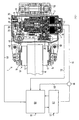
- Electromechanical brake application device forms one of several Brake application devices of a rail vehicle, for example an S-Bru.
- the Brake application device 1 includes a brake actuator 2 with a Service brake unit and a memory brake unit.
- the service brake unit has one electric drive, for example an electric servomotor 4, which in one Actuator housing 6 of the brake actuator 2 is housed.
- a mechanical one Power converter 8 is used to convert the energy output by the brake actuator 2 into a brake application movement.
- the actuator 4 sets a coaxial brake spindle 10 in rotation, which by the Power converter 8 in a brake application movement of brake pads 12 in the direction of a shaft brake disc 14 can be converted.
- the power converter 8 includes another a nut / spindle assembly 16 with one rotatable on the brake spindle 10 mounted spindle nut 18, which 10 linear movements when the brake spindle rotates can execute in the direction of the spindle axis 42.
- the end facing away from the servomotor 4 the brake spindle 10 projects into a cylindrical hollow section of a connecting rod 20 which is rotatably and axially fixed to the spindle nut 18.
- the connecting rod 20 held in a sliding sleeve 22 in a rotationally and axially fixed manner which acts at least one storage spring 24 supported on the actuator housing 6.
- the storage spring 24 is part of the storage brake unit and serves as an energy store Saving and delivering energy to apply the brake as operational Emergency brake in the sense of an underlying security level in the event of failure of the Service brake unit and / or as a parking or parking brake. Both the operational as The storage brake unit also acts on the connecting rod 20. The is in the brake release position Storage spring 24 by a locking device 26 in the biased position held.
- a connecting rod head 28 of the connecting rod 20 protrudes from the sliding sleeve 22 and is on one Brake lever 36 articulated perpendicular to the spindle axis 42 by means of a joint 40.
- a joint 40 At Drive the brake spindle 10 in the brake application direction or when the Locking device 26 of the storage spring 24 is then due to the axial extending connecting rods 20 a hinge pin of the joint 40, inter alia, by im claimed shear forces substantially perpendicular to the pin axis.
- the other end of the brake lever 36 acts on an eccentric arrangement with a Eccentric shaft 46, which is articulated to a pliers lever 48, which together with a further caliper lever 50 forms a brake caliper 52.
- the pliers levers at one end 48, 50 are each pad holder 54 with brake pads 12 arranged in the direction of Axis of the shaft brake disc 14 are displaceable.
- the brake pads 12 opposite ends of the pliers levers 48, 50 are connected to one another via a Push rod actuator 56 connected, which is preferably designed to be electrically actuated.
- the arrangement described also forms part of the power converter 8, which the Actuator 4 or extension movements of the connecting rod 20 caused by the storage spring 24 in a brake application movement of the brake pads 12 in the direction of the brake disc 14 converts.
- the hinge pin of the hinge 40 is preferably a shear force measuring pin 58 educated.
- the shear force measuring pin 58 is not with at least one for scale reasons provided sensor for measuring sizes, from which the to Brake pads 12 acting braking force can be derived indirectly or directly.
- the sensor is made using strain gauges (DMS) formed on the circumference of the shear force measuring bolt 58, preferably by gluing in this way are attached that they due to the opposing shear forces caused shear deformations of the shear force measuring pin 58 proportional signals produce.
- DMS strain gauges
- one or a plurality of strain gauges can be arranged on the brake lever 36 in order to avoid the deformations the brake lever 36 to be able to derive the braking forces.
- a strain gauge bridge circuit In an electronic evaluation system containing a strain gauge bridge circuit, one finds Conversion of the shear deformation signals into signals for those on the brake pads 12 acting actual application force instead, which via a signal line 59 to a control and Control device 60 are forwarded to a based on a target-actual comparison Control difference between a target application force and the actual application force to be calculated.
- the braking force setpoint is based, for example, on reaching one required target application force in the shortest possible time, for example 75% of the maximum Clamping force in 0.3 seconds.
- the control and regulating device 60 controls a power unit 62, which in An operating current for the servomotor 4 as a function of the calculated control difference modulates the by one to one between the power section 62 and the servomotor 4th running electrical line 64 connected current sensor 66 is measured, wherein a feedback to the control and regulating device 60 by a corresponding, via a signal line 68 is fed back motor current signal. Except for regulating one
- the signals applied to the control and regulating device 60 serve for the target application force for the actual application forces and for the respective motor current to monitor the Force control and functionality of the brake application device 1 safety-relevant braking. To verify the measurement results, the on the drive side by the current sensor 66 measured motor current in the control and Control device 60 can be compared with the signal for the actual application force.
- a temperature sensor 70 arranged in the motor winding of the servomotor 4 serves for Temperature monitoring during operation and delivers via a signal line 72 corresponding signals to the control and regulating device 60.
- further Temperature sensors for temperature monitoring of one or more Components of the brake application device 1 may be provided, for example a Temperature sensor for measuring the temperature of the power section 62.
- the brake application device 1 is preferably for generating load-corrected ones and / or slip-controlled braking forces, with a load-corrected one Braking a substantially to the current weight of the Braking force adapted to the rail vehicle and under a slip-controlled braking force a braking force should be understood by which the braking with ideal Wheel slip occurs (anti-skid control).
- control and regulating device 60 corresponding control functions.
- the control and regulating device 60 and that Power section 62 are preferably arranged directly on the brake caliper 52, in FIG. 1 For reasons of scale, however, drawn a little far from this.
- the tax and Control device 60 receives control signals from a central control unit of the S-Bru via a cable 61 and the power section 62 is available through a cable 63 Power supply in connection with the electrical system.
- the Control and regulating device 60 and the power section 62 but also far from Brake application device 1 arranged on a car body of a car of the S-Bru his.
- the brake application device 1 is on a bogie 74 of a car 76 of the rail vehicle, the brake disc 14 with a on the bogie 74 mounted axis 78 is rotatably connected.
- the bogie 74 can turn and Make vertical movements with respect to a body 80 of the carriage 76.
- a Energy and / or signal-transmitting connection of the brake application device 1 with a car body-side connection 82, which is associated with control, signal transmitters and / or Power supply facilities in car 76 or in another car in Contact is made by electrical movements of the bogie 74 tolerant Cable and / or optical fiber.
- the Brake application device 1 and the body 80 of the carriage 76 all electrical cables and / or optical fibers in a single integral cable 84 summarized, which with the brake application device 1 and / or with the Carriage box-side connection 82 is detachably connected.
- the cables 61 and 63 of FIG. 1 are guided within the integral cable 84. If however, the control and regulating electronics 60 and the power section 62 far from the Brake application device 1 are arranged on the car body 80, the line 64 and the signal line 72 in the integral cable 84.
- both ends of the integral cable 84 are both on the carriage side and on the brake application side using a detachable plug or screw connection 86, 88 connectable, the integral cable 84 being the distance between one on the ground of the car body 76 arranged terminal box 82 and a housing 90 of the Brake application device 1 bridges.
- a detachable plug or screw connection 86, 88 connectable, the integral cable 84 being the distance between one on the ground of the car body 76 arranged terminal box 82 and a housing 90 of the Brake application device 1 bridges.
- Any other type of solvable is also conceivable Connection.
- the car-side plug or screw connection 86 can, for example through a connector with a shield bracket and the brake application side Connector 88 can be realized by a circular connector.
- Integral cables 84 so are all the plug or screw connections 86, 88 contacts assigned to the individual cables and lines in a single contact Plug or integrated in a single socket.
- the integral cable 84 also by means of a tension-protected cable bushing in the housing 90 of the Brake application device 1 or open into the terminal box 82. It is crucial that at least one detachable connection 86, 88 is provided for the integral cable 84.
- the terminal box 82 is with a row of terminals not shown for reasons of scale which ends of cables and lines open, which of the control, Signal generator and / or energy supply devices are brought about.
- the single ones Terminals of the terminal series are in turn with assigned contacts car-side releasable connection 86 connected.
- the integral cable 84 is longer than that shortest connection between the brake application device side and the carriage-side releasable connection 86, 88 to allow unimpeded movement of the To enable bogie 74 with respect to the body 80.
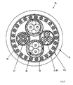
- Cables and lines 61, 63, 92, 94, 96 themselves each have several individual cables, each are surrounded by their own casing 98.
- the cables and Lines 61, 63, 92, 94, 96 also each have their own shielding.
- the integral cable sheath 91 is preferably fiber-reinforced, for example by metal or Carbon fibers, a metal knitted fabric for reinforcement is also conceivable.
- the radial inner surface of the integral cable sheath 91 is with a continuous overall shield 100 covered, which is preferably made of braided and lined with fleece There is shielding material.
- the control lines 96 for triggering safety and Parking brakes are preferably along the radially inner surface of the Overall shield 100 arranged circumferentially spaced and surround the other cables and lines 61, 63, 92, 94. Since the control and Control electronics 60 and the power section 62 preferably in the immediate vicinity is arranged to the brake caliper 52, the line 64 is not part of the Integral cable 84.
- control and regulating electronics 60 and the power section 62 do not like preferably arranged on the brake caliper 52 but remote from it on the car body 80 are in the integral cable 102, the lines 59, 64 and 72 as electrical Lines or optical fibers can be integrated in the integral cable 102.
- the integral cable sheath 116 can provide additional protection against mechanical damage have a further protective coating, for example in the form of a protective tube, which can also be integrated in the integral cable sheath 116 itself. All cables and in particular the integral cable sheath 116 consist of a material which resistant to high temperature fluctuations, large deformations, impact and Vibration load is.
Landscapes
- Engineering & Computer Science (AREA)
- Physics & Mathematics (AREA)
- General Engineering & Computer Science (AREA)
- Mechanical Engineering (AREA)
- General Physics & Mathematics (AREA)
- Optics & Photonics (AREA)
- Braking Systems And Boosters (AREA)
Abstract
Description
- Die Energieversorgung des Leistungsteils der Bremszuspanneinrichtung zum Auf- bzw. zum Abbau der Zuspannkraft;
- die Energieversorgung der Steuerung und Regelung der Bremszuspanneinrichtung;
- die Übermittlung von Steuersignalen wie beispielsweise das momentane Bremsanforderungssignal, Signale zum Auslösen der Parkbremsfunktion, zum Auslösen der Hilfsbremsfunktion etc.;
- die Übermittlung von Sensorsignalen wie beispielsweise die Signale eines Impulsgebers zur Ermittlung der Raddrehzahl oder von Endlagenschaltern;
- die Übermittlung von Diagnosedaten, etc.
- Fig. 1
- eine schematische Darstellung einer elektromechanischen Bremszuspanneinrichtung;
- Fig.2
- eine schematische Darstellung eines bevorzugten Ausführungsbeispiels einer Verbindung der Bremszuspannvorrichtung von Fig. 1 mit einem an einem Wagenboden angeordneten Klemmkasten mittels eines erfindungsgemäßen Integralkabels;
- Fig.3
- einen Querschnitt durch das Integralkabel von Fig.2;
- Fig.4
- einen Querschnitt durch ein weiteres Integralkabel.
- Impulsgebersignal- und Versorgungskabel 92 mit eigener Abschirmung, welche Signale eines an der Radnabe angeordneten Impulsgebers zur Drehzahlmessung des Rades sowie die für den Impulsgeber notwendige elektrische Energie übertragen,
- Feldbuskabel 94 eines CAN-Busses aus Kupfer mit eigener Abschirmung,
- Steuerleitungen 96 zum Auslösen von Sicherheits- und Parkbremsungen,
- die bereits in Fig. 1 dargestellten Kabel 61 und 63.
- Leistungsversorgungskabel 104 mit eigener Abschirmung,
- Impulsgebersignal- und Versorgungskabel 106 mit eigener Abschirmung,
- Feldbuskabel 108 als Lichtwellenleiter mit eigener Abschirmung,
- Steuerleitungen 110 zur Ansteuerung und Versorgung einer elektrischen Hilfslöseeinrichtung,
- Steuerleitungen 112 zum Auslösen von Sicherheits- und Parkbremsungen.
- 1
- Bremszuspanneinrichtung
- 2
- Bremsaktuator
- 4
- Stellmotor
- 6
- Aktuatorgehäuse
- 8
- Kraftumsetzer
- 10
- Bremsspindel
- 12
- Bremsbelag
- 14
- Bremsscheibe
- 16
- Mutter-/Spindel-Baueinheit
- 18
- Spindelmutter
- 20
- Pleuel
- 22
- Schiebehülse
- 24
- Speicherfeder
- 26
- Verriegelungseinrichtung
- 28
- Pleuelkopf
- 36
- Bremshebel
- 40
- Gelenk
- 42
- Spindelachse
- 46
- Exzenterwelle
- 48
- Zangenhebel
- 50
- Zangenhebel
- 52
- Bremszange
- 54
- Belaghalter
- 56
- Druckstangensteller
- 58
- Scherkraftmeßbolzen
- 59
- Signalleitung
- 60
- Steuer- und Regeleinrichtung
- 61
- Kabel
- 62
- Leistungsteil
- 63
- Kabel
- 64
- elektrische Leitung
- 66
- Stromsensor
- 68
- Signalleitung
- 70
- Temperatursensor
- 72
- Signalleitung
- 74
- Drehgestell
- 76
- Wagen
- 78
- Achse
- 80
- Wagenkasten
- 82
- Klemmkasten
- 84
- Integralkabel
- 86
- Steckverbindung
- 88
- Steckverbindung
- 90
- Gehäuse
- 91
- Integralkabelmantel
- 92
- Impulsgebersignal- und Versorgungskabel
- 94
- Feldbuskabel
- 96
- Steuerleitungen
- 98
- Ummantelungen
- 100
- Gesamtabschirmung
- 102
- Integralkabel
- 104
- Leistungsversorgungskabel
- 106
- Impulsgeber- und Versorgungskabel
- 108
- Feldbuskabel
- 110
- Steuerleitungen
- 112
- Steuerleitungen
- 114
- Füllmaterial
- 116
- Integralkabelmantel
- 118
- Gesamtabschirmung
Claims (14)
- Vorrichtung zur Verbindung einer elektromechanischen Bremszuspanneinrichtung einer Schienenfahrzeugbremse mit zugeordneten Steuer-, Signalgeber- und/oder Energieversorgungseinrichtungen (62), beinhaltend mehrere elektrische Kabel mit wenigstens einem Leistungsversorgungskabel (63; 104) und wenigstens einem signalführenden Kabel (61, 94, 96; 108, 110, 112), dadurch gekennzeichnet, daß zumindest zwischen der Bremszuspanneinrichtung (1) und einem Wagenkasten (80) eines zugeordneten Wagens (76) des Schienenfahrzeugs das wenigstens eine Leistungsversorgungskabel (63; 104) und das wenigstens eine signalführende Kabel (61, 94, 96; 108, 110, 112) in einem einzigen Integralkabel (84; 102) zusammengefaßt sind, wobei das wenigstens eine Leistungsversorgungskabel (63; 104) und/oder das wenigstens eine signalführende Kabel (61, 94, 96; 108, 110, 112) eine eigene Abschirmung aufweist bzw. aufweisen.
- Vorrichtung nach Anspruch 1, dadurch gekennzeichnet, daß zusätzlich wenigstens ein Lichtwellenleiter in das Integralkabel (84; 102) integriert ist.
- Vorrichtung nach Anspruch 2, dadurch gekennzeichnet, daß sämtliche elektrischen Kabel (61, 63, 92, 94, 96; 104, 106, 108, 110, 112) und der wenigstens eine Lichtwellenleiter innerhalb eines Kabelmantels (91; 116) des Integralkabels (84; 102) geführt sind.
- Vorrichtung nach Anspruch 3, dadurch gekennzeichnet, daß der Kabelmantel (91; 116) mit einer eigenen Abschirmung (100; 118) versehen ist.
- Vorrichtung nach Anspruch 3 oder 4, dadurch gekennzeichnet, daß zumindest einige der innerhalb des Kabelmantels (91; 116) geführten elektrischen Kabel (61, 63, 92, 94, 96; 104, 106, 108, 110, 112) und der wenigstens eine Lichtwellenleiter jeweils eine eigene Ummantelung (98) aufweisen.
- Vorrichtung nach einem der Ansprüche 3 bis 5, dadurch gekennzeichnet, daß der Kabelmantel (91; 116) faserverstärkt und/oder metallgestrickverstärkt ist.
- Vorrichtung nach einem der vorhergehenden Ansprüche, dadurch gekennzeichnet, daß das Integralkabel (84; 102) zur Leitung von Lichtwellen, analoger und/oder digitaler Signale vorgesehen ist.
- Vorrichtung nach einem der vorhergehenden Ansprüche, dadurch gekennzeichnet, daß das Integralkabel (102) das wenigstens eine Leistungsversorgungskabel (104) und eines oder mehrere der folgenden Kabel beinhaltet: Impulsgebersignal- und Versorgungskabel (106), Feldbuskabel (108), Steuerleitungen (110) zur Ansteuerung und Versorgung einer elektrischen Hilfslöseeinrichtung, Steuerleitungen (112) zur Ansteuerung und Versorgung einer Park- und Sicherheitsbremseinheit.
- Vorrichtung nach einem der vorhergehenden Ansprüche, dadurch gekennzeichnet, daß die Bremszuspanneinrichtung (1) an einem Drehgestell (74) des Wagens (76) und zumindest einige der Steuer-, Signalgeber- und/oder Energieversorgungseinrichtungen (62) in diesem und/oder in einem anderen Wagen angeordnet sind.
- Vorrichtung nach Anspruch 9, dadurch gekennzeichnet, daß das Integralkabel (84; 102) zwischen einem Gehäuse (90) der Bremszuspanneinrichtung (1) und dem Wagenkasten (80) des zugeordneten Wagens (76) verläuft.
- Vorrichtung nach Anspruch 10, dadurch gekennzeichnet, daß das Integralkabel (84; 102) mit der Bremszuspanneinrichtung (1) und/oder mit einem Anschluß (82) am Wagenkasten (80) lösbar verbunden ist.
- Vorrichtung nach Anspruch 11, dadurch gekennzeichnet, daß beide Enden des Integralkabels (84; 102) mittels je einer lösbaren Verbindung (86, 88) befestigt sind.
- Vorrichtung nach Anspruch 12, dadurch gekennzeichnet, daß an dem Wagenkasten (80) ein Klemmkasten (82) mit wenigstens einer Klemmenreihe festgelegt ist, in welche von den Steuer-, Signalgeber- und/oder Energieversorgungseinrichtungen (62) hergeführte Enden von Kabeln und Leitungen münden und welche der wagenseitigen lösbaren Verbindung (86) des Integralkabels (84; 102) zugeordnet ist.
- Vorrichtung nach Anspruch 13, dadurch gekennzeichnet, daß der Klemmkasten (82) an einer Unterseite des Wagenkastens (80) angeordnet ist.
Applications Claiming Priority (2)
| Application Number | Priority Date | Filing Date | Title |
|---|---|---|---|
| DE10239696A DE10239696B3 (de) | 2002-08-29 | 2002-08-29 | Vorrichtung zur Verbindung einer elektromechanischen Bremszuspanneinrichtung einer Schienenfahrzeugbremse mit zugeordneten Steuer-, Signalgeber- und/oder Energieversorgungseinrichtungen |
| DE10239696 | 2002-08-29 |
Publications (2)
| Publication Number | Publication Date |
|---|---|
| EP1394819A2 true EP1394819A2 (de) | 2004-03-03 |
| EP1394819A3 EP1394819A3 (de) | 2004-11-10 |
Family
ID=31197483
Family Applications (1)
| Application Number | Title | Priority Date | Filing Date |
|---|---|---|---|
| EP03018781A Withdrawn EP1394819A3 (de) | 2002-08-29 | 2003-08-28 | Vorrichtung zur Verbindung einer elektromechanischen Bremszuspanneinrichtung einer Schienenfahrzeugbremse mit zugeordneten Steuer-, Signalgeber- und/oder Energieversorgungseinrichtungen |
Country Status (2)
| Country | Link |
|---|---|
| EP (1) | EP1394819A3 (de) |
| DE (1) | DE10239696B3 (de) |
Cited By (8)
| Publication number | Priority date | Publication date | Assignee | Title |
|---|---|---|---|---|
| CN103928127A (zh) * | 2014-03-28 | 2014-07-16 | 江苏通鼎光电科技有限公司 | 一种铝护套挤包型的铁路信号电缆 |
| CN104376905A (zh) * | 2014-11-18 | 2015-02-25 | 中天日立射频电缆有限公司 | 城市轨道交通用计轴电缆及其制作方法 |
| EP2944528A1 (de) * | 2014-04-19 | 2015-11-18 | STILL GmbH | Bremsvorrichtung für fahrzeug sowie fahrzeug |
| CN105336430A (zh) * | 2015-11-30 | 2016-02-17 | 无锡江南电缆有限公司 | 一种城市轨道交通用动控复合电缆 |
| CN106098213A (zh) * | 2016-08-31 | 2016-11-09 | 无锡江南电缆有限公司 | 一种通信电缆 |
| CN109087736A (zh) * | 2018-08-20 | 2018-12-25 | 安徽新科电缆集团股份有限公司 | 一种抗拉阻燃型硅橡胶电缆 |
| IT202100031565A1 (it) * | 2021-12-16 | 2023-06-16 | Faiveley Transport Italia Spa | Attuatore elettromeccanico per un sistema di frenatura di un veicolo, sistema di frenatura e veicolo |
| DE102024101040A1 (de) * | 2024-01-15 | 2025-07-17 | Bayerische Motoren Werke Aktiengesellschaft | Kabelbaum, Fortbewegungsmittel, kombinierte Leitung und Verwendung einer kombinierten Leitung umfassend eine elektrische Leitung und eine optische Leitung |
Families Citing this family (2)
| Publication number | Priority date | Publication date | Assignee | Title |
|---|---|---|---|---|
| DE102006055859B4 (de) * | 2006-11-22 | 2009-02-12 | Siemens Ag | Elektromechanische Bremse mit dezentralen Generatoren |
| DE102018000509A1 (de) | 2017-02-02 | 2018-08-02 | Sew-Eurodrive Gmbh & Co Kg | Hybridkabel mit integriertem Lichtwellenleiter |
Family Cites Families (8)
| Publication number | Priority date | Publication date | Assignee | Title |
|---|---|---|---|---|
| US4318350A (en) * | 1979-12-03 | 1982-03-09 | The Budd Company | Overhead wiring arrangement for a railway car |
| US5530203A (en) * | 1995-02-28 | 1996-06-25 | Rotor Tool Company | Composite electrical conductor cable having internal magnetic flux shield |
| DE29520915U1 (de) * | 1995-03-04 | 1996-05-02 | Alcatel Kabel AG & Co., 30179 Hannover | Nachrichtenkabel |
| DE19508888C2 (de) * | 1995-03-11 | 1998-04-09 | Alcatel Kabel Ag | Flexible elektrische Starkstromleitung |
| DE29716946U1 (de) * | 1997-09-16 | 1999-01-21 | Siemens AG, 80333 München | Optisches Übertragungskabel für die Anordnung in einem Energieübertragungskabel |
| DE19843178C1 (de) * | 1998-09-21 | 2000-03-16 | Siemens Ag | Elektromechanische Kraftfahrzeug-Bremsvorrichtung |
| DE19945701A1 (de) * | 1999-09-23 | 2001-04-19 | Knorr Bremse Systeme | Bremsaktuator |
| DE20114231U1 (de) * | 2001-08-29 | 2001-11-29 | LEONI Protec Cable Systems GmbH, 98574 Schmalkalden | Industrieroboter |
-
2002
- 2002-08-29 DE DE10239696A patent/DE10239696B3/de not_active Expired - Fee Related
-
2003
- 2003-08-28 EP EP03018781A patent/EP1394819A3/de not_active Withdrawn
Cited By (10)
| Publication number | Priority date | Publication date | Assignee | Title |
|---|---|---|---|---|
| CN103928127A (zh) * | 2014-03-28 | 2014-07-16 | 江苏通鼎光电科技有限公司 | 一种铝护套挤包型的铁路信号电缆 |
| EP2944528A1 (de) * | 2014-04-19 | 2015-11-18 | STILL GmbH | Bremsvorrichtung für fahrzeug sowie fahrzeug |
| CN104376905A (zh) * | 2014-11-18 | 2015-02-25 | 中天日立射频电缆有限公司 | 城市轨道交通用计轴电缆及其制作方法 |
| CN105336430A (zh) * | 2015-11-30 | 2016-02-17 | 无锡江南电缆有限公司 | 一种城市轨道交通用动控复合电缆 |
| CN106098213A (zh) * | 2016-08-31 | 2016-11-09 | 无锡江南电缆有限公司 | 一种通信电缆 |
| CN109087736A (zh) * | 2018-08-20 | 2018-12-25 | 安徽新科电缆集团股份有限公司 | 一种抗拉阻燃型硅橡胶电缆 |
| CN109087736B (zh) * | 2018-08-20 | 2023-10-27 | 安徽新科电缆集团股份有限公司 | 一种抗拉阻燃型硅橡胶电缆 |
| IT202100031565A1 (it) * | 2021-12-16 | 2023-06-16 | Faiveley Transport Italia Spa | Attuatore elettromeccanico per un sistema di frenatura di un veicolo, sistema di frenatura e veicolo |
| WO2023111972A1 (en) * | 2021-12-16 | 2023-06-22 | Faiveley Transport Italia S.P.A. | Electromechanical actuator for a braking system of a vehicle, braking system and vehicle |
| DE102024101040A1 (de) * | 2024-01-15 | 2025-07-17 | Bayerische Motoren Werke Aktiengesellschaft | Kabelbaum, Fortbewegungsmittel, kombinierte Leitung und Verwendung einer kombinierten Leitung umfassend eine elektrische Leitung und eine optische Leitung |
Also Published As
| Publication number | Publication date |
|---|---|
| EP1394819A3 (de) | 2004-11-10 |
| DE10239696B3 (de) | 2004-03-25 |
Similar Documents
| Publication | Publication Date | Title |
|---|---|---|
| DE10239696B3 (de) | Vorrichtung zur Verbindung einer elektromechanischen Bremszuspanneinrichtung einer Schienenfahrzeugbremse mit zugeordneten Steuer-, Signalgeber- und/oder Energieversorgungseinrichtungen | |
| DE102009032754A1 (de) | Antriebsvorrichtung für einen Anhänger | |
| WO2003082651A1 (de) | Verfahren und vorrichtung zur ansteuerung einer elektrisch betätigten verschleissnachstelleinrichtung | |
| EP3426587B1 (de) | Tragmittel für eine aufzuganlage mit mehreren entlang des tragmittels angeordneten sensoren | |
| EP1448421A1 (de) | Elektrische bremseinrichtung für fahrzeuganhänger und verfahren zu deren betätigung | |
| DE102013008227A1 (de) | Verfahren und Vorrichtung zum Bestimmen eines Bremsmoments an einer Bremsanlage für ein Schienenfahrzeug | |
| DE102010025475A1 (de) | Stellsystem eines Flugzeugs mit einer Stellklappe | |
| DE102008015873A1 (de) | Fahrzeug, insbesondere Schienenfahrzeug, mit einer Einrichtung zur Überwachung der Bremswirkung | |
| EP3509923B1 (de) | Mehrteilig ausgeführte bremsregelung | |
| EP0601681A1 (de) | Verfahren und Einrichtung zum Einstellen der Bremskraft an Bremsscheiben von Schienenfahrzeugen | |
| EP2838752B1 (de) | Verfahren und einrichtung zur stromabnehmerausfallüberwachung | |
| WO2019001951A1 (de) | Schienenfahrzeug mit sensoreinrichtung zur messung von reibungsbremskräften einer reibungsbremseinrichtung | |
| EP2888147B9 (de) | Vorrichtung für ein schienenfahrzeug | |
| EP3299192B1 (de) | Zusatzbremseinrichtung für einen fahrzeuganhänger mit auflaufbremse | |
| DE10239695C1 (de) | Elektrische Verkabelung eines Fahrzeugs | |
| EP1362194B1 (de) | Elektromechanische bremszuspanneinrichtung | |
| DE102012015357B4 (de) | Nichtschaltbare Kupplung mit Drehmomentüberwachung | |
| DE10106374C2 (de) | Verfahren zur Reduktion der Betriebstemperatur elektromechanischer Bremszuspanneinrichtungen einer Fahrzeugbremse | |
| DE10347115B3 (de) | Bremszuspanneinrichtung einer Schienenfahrzeugbremse | |
| EP2187491A1 (de) | Elektrische Leitung für Kraftfahrzeuge | |
| DE10164718B4 (de) | Verfahren zur Reduktion der Betriebstemperatur elekromechanischer Bremszuspanneinrichtungen einer Fahrzeugbremse | |
| EP2888146B1 (de) | Vorrichtung für ein schienenfahrzeug | |
| DE102005051146B4 (de) | Verfahren und Prüfvorrichtung zum Prüfen und Einstellen des Lüftspiels einer Radbremse eines Kraftfahrzeuges | |
| EP3180535B1 (de) | Bremsvorrichtung | |
| EP1726473A1 (de) | Kraftmesseinrichtung und Verfahren zur Bestimmung einer Seitenführungskraft |
Legal Events
| Date | Code | Title | Description |
|---|---|---|---|
| PUAI | Public reference made under article 153(3) epc to a published international application that has entered the european phase |
Free format text: ORIGINAL CODE: 0009012 |
|
| AK | Designated contracting states |
Kind code of ref document: A2 Designated state(s): AT BE BG CH CY CZ DE DK EE ES FI FR GB GR HU IE IT LI LU MC NL PT RO SE SI SK TR |
|
| AX | Request for extension of the european patent |
Extension state: AL LT LV MK |
|
| PUAL | Search report despatched |
Free format text: ORIGINAL CODE: 0009013 |
|
| AK | Designated contracting states |
Kind code of ref document: A3 Designated state(s): AT BE BG CH CY CZ DE DK EE ES FI FR GB GR HU IE IT LI LU MC NL PT RO SE SI SK TR |
|
| AX | Request for extension of the european patent |
Extension state: AL LT LV MK |
|
| 17P | Request for examination filed |
Effective date: 20050510 |
|
| AKX | Designation fees paid |
Designated state(s): AT BE BG CH CY CZ DE DK EE ES FI FR GB GR HU IE IT LI LU MC NL PT RO SE SI SK TR |
|
| STAA | Information on the status of an ep patent application or granted ep patent |
Free format text: STATUS: THE APPLICATION HAS BEEN WITHDRAWN |
|
| 18W | Application withdrawn |
Effective date: 20100528 |