EP1394591A1 - Zoom lens and image pickup apparatus - Google Patents
Zoom lens and image pickup apparatus Download PDFInfo
- Publication number
- EP1394591A1 EP1394591A1 EP03255357A EP03255357A EP1394591A1 EP 1394591 A1 EP1394591 A1 EP 1394591A1 EP 03255357 A EP03255357 A EP 03255357A EP 03255357 A EP03255357 A EP 03255357A EP 1394591 A1 EP1394591 A1 EP 1394591A1
- Authority
- EP
- European Patent Office
- Prior art keywords
- lens
- lens element
- negative
- object side
- positive
- Prior art date
- Legal status (The legal status is an assumption and is not a legal conclusion. Google has not performed a legal analysis and makes no representation as to the accuracy of the status listed.)
- Granted
Links
- 230000003287 optical effect Effects 0.000 claims abstract description 53
- 239000002131 composite material Substances 0.000 claims description 3
- 238000006243 chemical reaction Methods 0.000 claims 1
- 230000004075 alteration Effects 0.000 description 28
- 238000010586 diagram Methods 0.000 description 19
- 230000014509 gene expression Effects 0.000 description 14
- 239000011521 glass Substances 0.000 description 3
- 239000004973 liquid crystal related substance Substances 0.000 description 2
- 239000000463 material Substances 0.000 description 2
- 230000009467 reduction Effects 0.000 description 2
- 230000001629 suppression Effects 0.000 description 2
- 230000009471 action Effects 0.000 description 1
- 230000000694 effects Effects 0.000 description 1
- 230000004048 modification Effects 0.000 description 1
- 238000012986 modification Methods 0.000 description 1
- 230000004044 response Effects 0.000 description 1
- 239000004065 semiconductor Substances 0.000 description 1
- 230000035945 sensitivity Effects 0.000 description 1
Images


Classifications
-
- G—PHYSICS
- G02—OPTICS
- G02B—OPTICAL ELEMENTS, SYSTEMS OR APPARATUS
- G02B15/00—Optical objectives with means for varying the magnification
- G02B15/14—Optical objectives with means for varying the magnification by axial movement of one or more lenses or groups of lenses relative to the image plane for continuously varying the equivalent focal length of the objective
- G02B15/142—Optical objectives with means for varying the magnification by axial movement of one or more lenses or groups of lenses relative to the image plane for continuously varying the equivalent focal length of the objective having two groups only
-
- G—PHYSICS
- G02—OPTICS
- G02B—OPTICAL ELEMENTS, SYSTEMS OR APPARATUS
- G02B15/00—Optical objectives with means for varying the magnification
- G02B15/14—Optical objectives with means for varying the magnification by axial movement of one or more lenses or groups of lenses relative to the image plane for continuously varying the equivalent focal length of the objective
- G02B15/144—Optical objectives with means for varying the magnification by axial movement of one or more lenses or groups of lenses relative to the image plane for continuously varying the equivalent focal length of the objective having four groups only
- G02B15/1441—Optical objectives with means for varying the magnification by axial movement of one or more lenses or groups of lenses relative to the image plane for continuously varying the equivalent focal length of the objective having four groups only the first group being positive
Definitions
- the present invention relates to a zoom lens with a wide angle of view and a high magnification, suitable for an image pickup apparatus such as a digital still camera, a video camera, or a television camera, etc.
- a zoom lens comprising, in order from the object side, a first lens unit with positive optical power, a second lens unit with negative optical power, having a magnification varying function, and at least one other lens unit has been known.
- the first lens unit is provided with a retro focus type optical arrangement including a first lens component having negative optical power and a second lens component having positive optical power, wherein the first lens component has, in order from the object side, one negative lens element whose concave surface is faced to the object side, and one or more lens elements.
- a zoom lens is disclosed in Japanese Patent Application Laid-Open No. H08(1996)-184758 (corresponding to US Patent No. 5831771).
- this zoom lens is frequently used as a wide-angle and high-magnification zoom lens whose zooming ratio exceeds 10 times.
- the light ray incident angle onto the first surface of the negative lens element in the first lens unit increases, and distortion components in chromatic aberration of magnification significantly increase although positive distortion is satisfactorily corrected.
- a concern of the invention is to provide a small-sized lightweight zoom lens with a wide angle of view and a high magnification, having high optical performance by setting the lens structure and conditions properly.
- a zoom lens comprising, in order from the object side, a first lens unit having positive optical power, a second lens unit having negative optical power and has a magnification varying function, and at least one other lens unit.
- the first lens unit includes, in order from the object side, a first negative lens element whose object side surface is concave toward the object side, and a second negative lens element, and at least one positive lens element is closer to the image plane side than the second negative lens element.
- the zoom lens satisfies the following condition: - 1.28 ⁇ fn / f1 where fn denotes the composite focal length of the first negative lens element and the second negative lens element, and f1 denotes the focal length of the first lens unit.
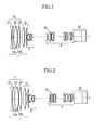
- Fig. 1, Fig. 2, and Fig. 3 are sectional views of zoom lenses of respective Embodiments 1, 2, and 3 when they are at the wide-angle end and focused to infinity.
- numerical reference 1 denotes a first lens unit which has a focusing function and has positive optical power.
- Numerical reference 2 denotes a second lens unit which has a magnification varying function by moving on the optical axis and has negative optical power.
- Numerical referee 3 denotes third lens unit which moves on the optical axis when varying the magnification and corrects image plane variation caused by magnification varying.
- Numerical reference 4 denotes a fourth lens unit which has a function forming an image on the image plane and has positive optical power.
- Numerical reference 31 denotes an aperture stop.
- Numerical reference 32 denotes an optical unit including a color separating optical system and an optical filter, etc., which are shown by glass blocks corresponding to them in the figures.
- the first lens unit 1 comprises, in order from the object side, a first lens component 11 which has negative optical power and is fixed when focusing, and a second lens component 12 which has positive optical power and moves on the optical axis when focusing.
- the first lens component 11 includes, in order from the object side, a first negative lens element in which a first surface at the extreme object side is concave toward the object side, a second negative lens element, and at least one positive lens element.
- first lens component 11 which comprises, in order from the object side, a first negative lens element 21 and a second lens element unit 22 including a second negative lens element 22a and a positive lens element 22b is shown.
- the radius of curvature of the first surface of the first negative lens element 21 can be increased even when the negative optical power of the first lens component 11 and the positive optical power of the second lens component 12 are increased for a wider field angle of view and reduction in size and in weight of the zoom lens. Therefore, it becomes possible to suppress distortion components in chromatic aberration of magnification while satisfactorily correcting positive distortion which becomes maximum at a zooming position of fw ⁇ Z 1/4 provided that the focal length at the wide-angle end is fw and the zooming ratio is Z.
- Embodiments 1 and 2 an example in which a positive lens element 23 is disposed closer to the image plane side than the positive lens element 22b is shown.
- this positive lens element 23 By disposing this positive lens element 23, the height of refraction point of off-axis light ray at the wide-angle side can be lowered in addition to the abovementioned effects, so that the diameter of the front lens (the first lens component 11) can be reduced.
- a structure of , in order from the object side, negative, negative, and positive is employed, however, a structure of negative, negative, negative, and positive may be employed.
- the radius of curvature of the first surface of the first negative lens element 21 can be increased, and a glass material having a large Abbe's number can be used for the first negative lens element 21, so that suppression of distortion components in chromatic aberration of magnification is possible.
- fn denotes the composite focal length of the first negative lens element 21 and the second negative lens element 22a
- f1 denotes the focal length of the first lens unit 1.
- v1 and v2 indicate Abbe's numbers of the first negative lens element 21 and the second negative lens element 22a, respectively.
- v3 denotes Abbe's number of the positive lens element which is disposed closer to the image plane side than the second negative lens element 22a and the closest to the object side within the first lens unit excluding the first negative lens element 21 and the second negative lens element 22a.
- Expressions (2) and (3) indicate a condition required for achieving correction of both distortion components in chromatic aberration of magnification and axial chromatic aberration at the telephoto end. If v1 - v2 and v3 are equal to or lower than the lower limit of Expressions (2) and (3), respectively, distortion components in chromatic aberration of magnification cannot be satisfactorily corrected, resulting in lowering in image quality.
- the zoom lens satisfies the following conditional expressions: Z > 10 fw / IS ⁇ 0.75
- Z denotes a zooming ratio
- fw denotes a focal length of the entire system at the wide-angle end
- IS denotes an image size
- Expression (4) means that the zoom lens is a high-magnification zoom lens having a zooming ratio exceeding 10 times. If the zooming ratio Z becomes lower than the lower limit of Expression (4), it becomes unnecessary to increase the positive optical power of the first lens unit 1 and the negative optical power of the second lens unit 2, and distortion components in chromatic aberration of magnification can be suppressed while positive distortion is properly corrected even in the conventional structure. Therefore, the arrangement of a negative lens element, a negative lens element, and a positive lens element in order from the object side in the first lens component 11 becomes unnecessary.
- Expression (5) means that the field angle at the wide-angle end is 67 degrees or more.
- fw/IS becomes greater than the upper limit of (5), it becomes unnecessary to increase the positive optical power of the first lens unit 1 and the negative optical power of the second lens unit 2, and the arrangement of a negative lens element, a negative lens element, and a positive lens element in order from the object side in the first lens component 11 becomes unnecessary.
- All zoom lenses of Embodiments 1, 2, and 3 are high-magnification and wide-angle zoom lenses satisfying Expressions (1), (2), (3), (4) and (5) as shown in Tables 1, 2, and 3 below, wherein the first lens component 11 comprises, in order from the object side, a negative lens element, a negative lens element, and a positive lens element.
- the first lens component 11 constituting part of the first lens unit 1 includes, in order from the object side, the negative lens element 21 whose first surface is concave toward the object side, the second negative lens element 22a, and the positive lens element 22b, it is desirable that the following condition is satisfied: hw ⁇ hz
- hw and hz show the maximum heights of off-axis light rays at the maximum image height, which pass through the first surface of the first lens unit 1 (the first negative lens element 21) when the zoom lens is focused to infinity at the wide-angle end and at a focal length of fw ⁇ Z 1/4 , respectively.
- the zoom lens satisfying Expression (5) in a case where positive distortion is corrected, correction by the first surface of the first negative lens element 21 in the first lens component 11 satisfying hw ⁇ hz is most suitable. Therefore, distortion components in chromatic aberration of magnification easily occur. Therefore, in the zoom lens satisfying Expression (6), the first lens component 11 is composed of, in order from the object side, a negative lens element, a negative lens element, and a positive lens element.
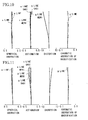
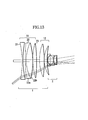
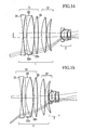
- Fig. 13 through Fig. 18 are optical path diagrams showing off-axis light rays at the maximum image height that pass through the first surface of the first lens unit 1 at the wide-angle end and at a focal length of fw ⁇ Z 1/4 in Embodiment 1, Embodiment 2, and Embodiment 3.
- the first lens component 11 includes a negative lens element, a negative lens element, and a positive lens element.
- the second negative lens element 22a and the positive lens element 22b, which form the first lens component 11, are cemented together.
- the positive lens element 22b has a function to correct spherical aberration at the telephoto end, however, in a case where an air space exists between the second negative lens element 22a and the positive lens element 22b, the sensitivity of spherical aberration to the interval between the second negative lens element 22a and the positive lens element 22b increases, resulting in more production difficulty. Therefore, it is preferable that the second negative lens element 22a and the positive lens element 22b are cemented together to form the second lens element unit 22 as a cemented lens.
- Numerical data of the zoom lens of Embodiment 1 shown in Fig. 1 is shown in Table 1
- numerical data of the zoom lens of Embodiment 2 shown in Fig. 2 is shown in Table 2
- numerical data of the zoom lens of Embodiment 3 shown in Fig. 3 is shown in Table 3.
- ri denotes the radius of curvature of the i-th surface in order from the object side
- di denotes the interval between the i-th surface and (i+1)th surface
- ni and vi are the refractive index and Abbe's number of the glass material forming the i-th surface, respectively.
- the surface attached with an "*" indicates that the surface is an aspherical surface.
- Embodiment 1 Embodiment 1
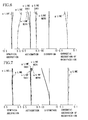
- Embodiment 2 and Embodiment 3 aberration diagrams when the lenses are at the wide-angle end and focused to infinity
- aberration diagrams when the lenses are focused to infinity at a focal length of fw ⁇ Z 1/4 aberration diagrams when the lenses are at the telephoto end and focused to infinity are shown in Figs. 4 through Figs. 12.
- a zoom lens which is small in size and lightweight while having high optical performance, a wide field angle, and a high magnification is realized.
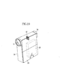
- Fig. 19 shows a video camera (image pickup apparatus) using the zoom lens described in each embodiment as an image-taking optical system.
- numerical reference 50 denotes the main body of the video camera
- 51 denotes an image-taking optical system comprising the zoom lens described in each embodiment
- 52 denotes an image pickup element as a photoelectrically converting element such as a CCD or a CMOS sensor, etc., which receives and photoelectrically converts an object image formed by the image-taking optical system 51.
- a recording medium 53 is a semiconductor memory, a magnetic disk, or an optical disk, etc., which records image signals obtained through the image pickup element 52.
- a finder 54 is for observation of an object image displayed on an internal display panel (not shown) such as a liquid crystal panel, etc., in response to the image signals obtained through the image pickup element 52.
- An external display panel 55 has a function equivalent to that of the finder 54, and is a liquid crystal panel, etc., which displays object images and various image-taking information.
- This external display panel 55 can be housed in and developed from the video camera main body 50, and the housed condition is shown in the figure.
- an image pickup apparatus which is small in size and lightweight while having high image pickup performance and enables image-taking with a wide field angle and a high magnification is realized.
- the zoom lens described in each embodiment mentioned above can be used for various image pickup apparatuses including digital still cameras, television cameras, and film cameras as well as video cameras.
Landscapes
- Physics & Mathematics (AREA)
- General Physics & Mathematics (AREA)
- Optics & Photonics (AREA)
- Lenses (AREA)
Abstract
Description
- The present invention relates to a zoom lens with a wide angle of view and a high magnification, suitable for an image pickup apparatus such as a digital still camera, a video camera, or a television camera, etc.
- Conventionally, a zoom lens comprising, in order from the object side, a first lens unit with positive optical power, a second lens unit with negative optical power, having a magnification varying function, and at least one other lens unit has been known. In this zoom lens, the first lens unit is provided with a retro focus type optical arrangement including a first lens component having negative optical power and a second lens component having positive optical power, wherein the first lens component has, in order from the object side, one negative lens element whose concave surface is faced to the object side, and one or more lens elements. Such a zoom lens is disclosed in Japanese Patent Application Laid-Open No. H08(1996)-184758 (corresponding to US Patent No. 5831771).
- In such a zoom lens, since the back side principal point of the first lens unit is pushed out toward the image plane side, the effective diameter of the first lens unit can be reduced to be comparatively small. Therefore, this zoom lens is frequently used as a wide-angle and high-magnification zoom lens whose zooming ratio exceeds 10 times.
- Herein, for the zoom lens, reduction in size and weight has been strongly demanded as well as achievement of both a wide angle of view and a high magnification.
- However, in the conventional structure such as disclosed in Japanese Patent Application Laid-Open No. H08(1996)-184758 (corresponding to US Patent No. 5831771), when it is attempted to realize a smaller size while achieving a wider angle of view, it becomes necessary to increase the negative optical power of the first lens component and the positive optical power of the second lens component.
- If the positive optical power of the second lens component increases, positive distortion increases at a zooming position (focal length) of fw × Z1/4 provided that the focal length at the wide-angle end is fw and the zooming ratio is Z.
- Furthermore, in addition to the increase in the negative optical power of the first lens component, in a case where the positive distortion is corrected, on the assumption that the maximum height of the maximum image height off-axis light ray at the wide-angle end in a condition where the object distance is infinity is defined as hw, and the same at a zooming position of fw × Z1/4 is defined as hz, the radius of curvature of the first surface (surface of the object side) of the negative lens element in the first lens component, satisfying hw < hz, becomes smaller.
- As a result, the light ray incident angle onto the first surface of the negative lens element in the first lens unit increases, and distortion components in chromatic aberration of magnification significantly increase although positive distortion is satisfactorily corrected.
- In order to correct this, it is necessary to make Abbe's number of the negative lens element in the first lens unit larger, however, this results in insufficient correction of axial chromatic aberration at the telephoto end, and it becomes difficult to achieve a wider angle and a higher magnification while maintaining high optical performance, furthermore, a smaller size and a lighter weight.
- A concern of the invention is to provide a small-sized lightweight zoom lens with a wide angle of view and a high magnification, having high optical performance by setting the lens structure and conditions properly.
- According to one aspect of the invention there is provided a zoom lens comprising, in order from the object side, a first lens unit having positive optical power, a second lens unit having negative optical power and has a magnification varying function, and at least one other lens unit. The first lens unit includes, in order from the object side, a first negative lens element whose object side surface is concave toward the object side, and a second negative lens element, and at least one positive lens element is closer to the image plane side than the second negative lens element. And the zoom lens satisfies the following condition:
- The characteristics of a zoom lens and an image pickup apparatus of the invention become clear by the following detailed description with reference to the accompanying drawings.
- Fig. 1 is a sectional view of a zoom lens of Embodiment 1 of the invention when it is at the wide-angle end and focused to infinity.
- Fig. 2 is a sectional view of a zoom lens of Embodiment 2 of the invention when it is at the wide-angle end and focused to infinity.
- Fig. 3 is a sectional view of a zoom lens of Embodiment 3 when it is at the wide-angle end and focused to infinity.
- Figs. 4 are aberration diagrams of Embodiment 1 when the lens is at the wide-angle end and focused to infinity.
- Figs. 5 are aberration diagrams of Embodiment 1 when the lens is focused to infinity at a focal length of fw × Z1/4.
- Figs. 6 are aberration diagrams of Embodiment 1 when the lens is at the telephoto end and focused to infinity.
- Figs. 7 are aberration diagrams of Embodiment 2 when the lens is at the wide-angle end and focused to infinity.
- Figs. 8 are aberration diagrams of Embodiment 2 when the lens is focused to infinity at a focal length of fw × Z1/4.
- Figs. 9 are aberration diagrams of Embodiment 2 when the lens is at the telephoto end and focused to infinity.
- Figs. 10 are aberration diagrams of Embodiment 3 when the lens is at the wide-angle end and focused to infinity.
- Figs. 11 are aberration diagrams of Embodiment 3 when the lens is focused to infinity at a focal length of fw × Z1/4.
- Figs. 12 are aberration diagrams of Embodiment 3 when the lens is at the telephoto end and focused to infinity.
- Fig. 13 is an optical path diagram of Embodiment 1 when the lens is at the wide-angle end and focused to infinity.
- Fig. 14 is an optical path diagram of Embodiment 1 when the lens is focused to infinity at a focal length of fw × Z1/4.
- Fig. 15 is an optical path diagram of Embodiment 2 when the lens is at the wide-angle end and focused to infinity.
- Fig. 16 is an optical path diagram of Embodiment 2 when the lens is focused to infinity at a focal length of fw × Z1/4.
- Fig. 17 is an optical path diagram of Embodiment 3 when the lens is at the wide-angle end and focused to infinity.
- Fig. 18 is an optical path diagram of Embodiment 3 when the lens is focused to infinity at a focal length of fw × Z1/4.
- Fig. 19 is a schematic view of an image pickup apparatus using the zoom lens of each abovementioned Embodiment.
-
- Hereinafter, Embodiments of the present invention are described with reference to the accompanying drawings.
- Fig. 1, Fig. 2, and Fig. 3 are sectional views of zoom lenses of respective Embodiments 1, 2, and 3 when they are at the wide-angle end and focused to infinity.
- In Fig. 1, Fig. 2, and Fig. 3, in order from an object side (left side of the drawings), numerical reference 1 denotes a first lens unit which has a focusing function and has positive optical power. Numerical reference 2 denotes a second lens unit which has a magnification varying function by moving on the optical axis and has negative optical power. Numerical referee 3 denotes third lens unit which moves on the optical axis when varying the magnification and corrects image plane variation caused by magnification varying. Numerical reference 4 denotes a fourth lens unit which has a function forming an image on the image plane and has positive optical power.
- Numerical reference 31 denotes an aperture stop. Numerical reference 32 denotes an optical unit including a color separating optical system and an optical filter, etc., which are shown by glass blocks corresponding to them in the figures.
- The first lens unit 1 comprises, in order from the object side, a first lens component 11 which has negative optical power and is fixed when focusing, and a second lens component 12 which has positive optical power and moves on the optical axis when focusing.
- The first lens component 11 includes, in order from the object side, a first negative lens element in which a first surface at the extreme object side is concave toward the object side, a second negative lens element, and at least one positive lens element.
- In this embodiment, an example of the first lens component 11 which comprises, in order from the object side, a first negative lens element 21 and a second lens element unit 22 including a second negative lens element 22a and a positive lens element 22b is shown.
- Thus, by making the first lens component 11 to include, in order from the object side, the negative lens element, the negative lens element, and at least one positive lens element, the radius of curvature of the first surface of the first negative lens element 21 can be increased even when the negative optical power of the first lens component 11 and the positive optical power of the second lens component 12 are increased for a wider field angle of view and reduction in size and in weight of the zoom lens. Therefore, it becomes possible to suppress distortion components in chromatic aberration of magnification while satisfactorily correcting positive distortion which becomes maximum at a zooming position of fw × Z1/4 provided that the focal length at the wide-angle end is fw and the zooming ratio is Z.
- Furthermore, in Embodiments 1 and 2, an example in which a positive lens element 23 is disposed closer to the image plane side than the positive lens element 22b is shown. By disposing this positive lens element 23, the height of refraction point of off-axis light ray at the wide-angle side can be lowered in addition to the abovementioned effects, so that the diameter of the front lens (the first lens component 11) can be reduced. Furthermore, in Embodiments 1, 2 , and 3 , a structure of , in order from the object side, negative, negative, and positive is employed, however, a structure of negative, negative, negative, and positive may be employed. With such a structure, the radius of curvature of the first surface of the first negative lens element 21 can be increased, and a glass material having a large Abbe's number can be used for the first negative lens element 21, so that suppression of distortion components in chromatic aberration of magnification is possible.
- Furthermore, it is desirable that the following conditional expression is satisfied.
- Furthermore, by satisfying the following conditional expression, it becomes possible to correct distortion components in chromatic aberration of magnification and axial chromatic aberration at the telephoto end while satisfactorily correcting positive distortion.
- Herein, v1 and v2 indicate Abbe's numbers of the first negative lens element 21 and the second negative lens element 22a, respectively. v3 denotes Abbe's number of the positive lens element which is disposed closer to the image plane side than the second negative lens element 22a and the closest to the object side within the first lens unit excluding the first negative lens element 21 and the second negative lens element 22a.
- Expressions (2) and (3) indicate a condition required for achieving correction of both distortion components in chromatic aberration of magnification and axial chromatic aberration at the telephoto end. If v1 - v2 and v3 are equal to or lower than the lower limit of Expressions (2) and (3), respectively, distortion components in chromatic aberration of magnification cannot be satisfactorily corrected, resulting in lowering in image quality.
- Furthermore, in a case where the first lens component 11 constituting part of the first lens unit 1 comprises, in order from the object side, the first negative lens element 21 whose first surface is concave toward the object side, the second negative lens element 22a, and the positive lens element 22b, it is desirable that the zoom lens satisfies the following conditional expressions:
- Herein, Z denotes a zooming ratio, fw denotes a focal length of the entire system at the wide-angle end, and IS denotes an image size.
- Expression (4) means that the zoom lens is a high-magnification zoom lens having a zooming ratio exceeding 10 times. If the zooming ratio Z becomes lower than the lower limit of Expression (4), it becomes unnecessary to increase the positive optical power of the first lens unit 1 and the negative optical power of the second lens unit 2, and distortion components in chromatic aberration of magnification can be suppressed while positive distortion is properly corrected even in the conventional structure. Therefore, the arrangement of a negative lens element, a negative lens element, and a positive lens element in order from the object side in the first lens component 11 becomes unnecessary.
- Expression (5) means that the field angle at the wide-angle end is 67 degrees or more. When fw/IS becomes greater than the upper limit of (5), it becomes unnecessary to increase the positive optical power of the first lens unit 1 and the negative optical power of the second lens unit 2, and the arrangement of a negative lens element, a negative lens element, and a positive lens element in order from the object side in the first lens component 11 becomes unnecessary.
- All zoom lenses of Embodiments 1, 2, and 3 are high-magnification and wide-angle zoom lenses satisfying Expressions (1), (2), (3), (4) and (5) as shown in Tables 1, 2, and 3 below, wherein the first lens component 11 comprises, in order from the object side, a negative lens element, a negative lens element, and a positive lens element.
- Furthermore, in a case where the first lens component 11 constituting part of the first lens unit 1 includes, in order from the object side, the negative lens element 21 whose first surface is concave toward the object side, the second negative lens element 22a, and the positive lens element 22b, it is desirable that the following condition is satisfied:
- Herein, hw and hz show the maximum heights of off-axis light rays at the maximum image height, which pass through the first surface of the first lens unit 1 (the first negative lens element 21) when the zoom lens is focused to infinity at the wide-angle end and at a focal length of fw × Z1/4, respectively.
- In such a zoom lens, in most cases, a negative lens element whose concave surface is faced to the image plane side is used as the first negative lens element 21 of the first lens unit 1. In the zoom lens satisfying Expression (5), in a case where positive distortion is corrected, correction by the first surface of the first negative lens element 21 in the first lens component 11 satisfying hw < hz is most suitable. Therefore, distortion components in chromatic aberration of magnification easily occur. Therefore, in the zoom lens satisfying Expression (6), the first lens component 11 is composed of, in order from the object side, a negative lens element, a negative lens element, and a positive lens element.
- Fig. 13 through Fig. 18 are optical path diagrams showing off-axis light rays at the maximum image height that pass through the first surface of the first lens unit 1 at the wide-angle end and at a focal length of fw × Z1/4 in Embodiment 1, Embodiment 2, and Embodiment 3.
- As shown in these figures and Tables 1 through 3, in this embodiment, in the zoom lenses satisfying Expression (6), the first lens component 11 includes a negative lens element, a negative lens element, and a positive lens element.
- As a more preferable embodiment, it is desirable that the second negative lens element 22a and the positive lens element 22b, which form the first lens component 11, are cemented together.
- The positive lens element 22b has a function to correct spherical aberration at the telephoto end, however, in a case where an air space exists between the second negative lens element 22a and the positive lens element 22b, the sensitivity of spherical aberration to the interval between the second negative lens element 22a and the positive lens element 22b increases, resulting in more production difficulty. Therefore, it is preferable that the second negative lens element 22a and the positive lens element 22b are cemented together to form the second lens element unit 22 as a cemented lens.
- Numerical data of the zoom lens of Embodiment 1 shown in Fig. 1 is shown in Table 1, numerical data of the zoom lens of Embodiment 2 shown in Fig. 2 is shown in Table 2, and numerical data of the zoom lens of Embodiment 3 shown in Fig. 3 is shown in Table 3.
- In these tables, ri denotes the radius of curvature of the i-th surface in order from the object side, di denotes the interval between the i-th surface and (i+1)th surface, and ni and vi are the refractive index and Abbe's number of the glass material forming the i-th surface, respectively.
- Furthermore, the surface attached with an "*" indicates that the surface is an aspherical surface. The shape of the aspherical surface satisfies the following expression when the direction of the optical axis is defined as the x axis, the direction perpendicular to the optical axis is defined as the y axis, the light ray advance direction is defined as positive, R is defined as the paraxial radius of curvature, and k, B, C, D, E, F, A', B', C', D', and E' are defined as aspherical coefficients:
Zooming ratio: 21x
Field angle at the wide-angle end: 70.4 degrees
í1-í2=29.3 í3=95.0 hw:5.13 hz:5.21
fn/f1=-1.07r1= -27.3632 d1= 0.2308 n1= 1.73234 í1= 54.7 r2= 27.3632 d2= 0.7159 r3= 71.3705 d3= 0.2308 n2= 1.81264 í2= 25.4 r4= 12.9897 d4= 1.9149 n3= 1.43985 í3= 95.0 r5= -20.8550 d5= 0.0192 r6= 22.4921 d6= 1.0621 n4= 1.62033 í4= 63.3 r7= -44.2413 d7= 0.8682 r8= 13.6623 d8= 1.3612 n5= 1.49845 í5= 81.5 r9= -38.6827 d9= 0.0192 r10= 8.5777 d10= 0.8358 n6= 1.73234 í6= 54.7 r11= 20.4377 d11=variable *r12= 17.4102 d12= 0.0897 n7= 1.88815 í7= 40.8 r13= 1.8153 d13= 0.7775 r14= -16.8508 d14= 0.8569 n8= 1.81643 í8= 22.8 r15= -1.7598 d15= 0.0897 n9= 1.82017 19= 46.6 r16= 6.2738 d16= 0.0207 r17= 3.0458 d17= 0.7632 n10= 1.53430 í10= 48.8 r18= -3.7054 d18= 0.0339 r19= -3.3339 d19= 0.0897 n11= 1.83945 í11= 42.7 r20= -33.1779 d20= variable r21= -3.6233 d21= 0.0897 n12= 1.74678 í12= 49.3 r22= 5.8983 d22= 0.3590 n13= 1.85504 í13= 23.8 r23= -168.4231 d23=variable r24= 0.0000 d24= 0.1667(aperture stop) r25= 140.3963 d25= 0.5587 n14= 1.66152 í14= 50.9 r26= -4.4981 d26= 0.0192 r27= 10.3658 d27= 0.3130 n15= 1.51825 í15= 64.1 r28= -3371.7949 d28= 0.0192 r29= 11.9041 d29= 0.8686 n16= 1.51825 í16= 64.1 r30= -4.1625 d30= 0.2308 n17= 1.83932 í17= 37.2 r31= -26.2383 d31= 4.5128 r32= 7.8669 d32= 0.8029 n18= 1.51825 í18= 64.1 r33= -6.7440 d33= 0.2219 r34= -12.6572 d34= 0.2308 n19= 1.83945 í19= 42.7 r35= 4.1168 d35= 0.7369 n20= 1.51977 í20= 52.4 r36= -11.6979 d36= 0.5637 r37= 7.9839 d37= 0.8684 n21= 1.48915 í21= 70.2 r38= -3.8229 d38= 0.2308 n22= 1.83932 í22= 37.2 r39= -45.5666 d39= 0.0192 r40= 6.8645 d40= 0.5644 n23= 1.52033 í23= 58.9 r41= -9.4753 d41= 0.5769 r42= 0.0000 d42= 3.8462 n24= 1.60718 í24= 38.0 r43= 0.0000 d43= 2.0769 n25= 1.51825 í25= 64.2 r44= 0.0000 d44= 0.9614 Focal length /Variable interval 1.00 2.14 4.06 14.60 21.00 d11 0.09 3.06 4.71 6.58 6.85 d20 7.14 3.74 1.80 0.45 0.70 d23 0.62 1.06 1.34 0.82 0.22 -

Zooming ratio: 18x
Field angle at the wide-angle end: 72.5 degrees
í1-í2=24.6 í3=95.0 hw:5.50 hz:5.52
fn/f1=-1.10r1= -28.9573 d1= 0.2400 n1= 1.79025 í1= 50.0 r2= 30.0203 d2= 0.8515 r3= 78.0457 d3= 0.2400 n2= 1.81264 í2= 25.4 r4= 13.9770 d4= 2.0645 n3= 1.43985 í3= 95.0 r5= -20.9743 d5= 0.0200 r6= 24.9264 d6= 1.1292 n4= 1.60520 í4= 65.4 r7= -39.7140 d7= 0.7266 r8= 14.2826 d8= 1.4278 n5= 1.49845 í5= 81.5 r9= -36.6365 d9= 0.0200 r10= 8.3007 d10= 0.8977 n6= 1.73234 í6= 54.7 r11= 18.7300 d11=variable *r12= 17.2263 d12= 0.0933 n7= 1.88815 í7= 40.8 r13= 2.0230 d13= 0.7765 r14= -16.8024 d14= 0.8726 n8= 1.81643 í8= 22.8 r15= -1.8979 d15= 0.0933 n9= 1.82017 í9= 46.6 r16= 5.0474 d16= 0.1466 r17= 3.2941 d17= 0.7571 n10= 1.57047 í10= 42.8 r18= -4.0079 d18= 0.0787 r19= -3.1712 d19= 0.0933 n11= 1.88815 í11= 40.8 r20= -18.0496 d20= variable r21 -3.5834 d21= 0.0933 n12= 1.74678 í12= 49.3 r22= 6.3668 d22= 0.3733 n13= 1.85504 í13= 23.8 r23= -97.8600 d23= variable r24= 0.0000 d24= 0.1733(aperture stop) r25= 168.4641 d25= 0.6109 n14= 1.66152 í14= 50.9 r26= -4.4111 d26= 0.0200 r27= 11.1625 d27= 0.3447 n15= 1.51977 í15= 52.4 r28= -1200.0000 d28= 0.0200 r29= 10.5857 d29= 0.7931 n16= 1.52458 í16= 59.8 r30= -3.9079 d30= 0.2400 n17= 1.83945 í17= 42.7 r31= -21.0878 d31= 3.3333 r32= 10.2483 d32= 0.7729 n18= 1.51825 í18= 64.1 r33= -5.8053 d33= 0.1364 r34= -9.2298 d34= 0.2400 n19= 1.83945 í19= 42.7 r35= 4.2865 d35= 1.1027 n20= 1.51825 í20= 64.1 r36= -7.7621 d36= 0.3999 r37= 10.0271 d37= 0.8147 n21= 1.48915 í21= 70.2 r38= -3.8930 d38= 0.2400 n22= 1.83932 í22= 37.2 r39= -25.1689 d39= 0.0366 r40= 7.0822 d40= 0.6865 n23= 1.51825 í23= 64.1 r41= -8.9491 d41= 0.6000 r42= 0.0000 d42= 4.0000 n24= 1.60718 í24= 38.0 r43= 0.0000 d43= 2.1600 n25= 1.51825 í25= 64.2 r44= 0.0000 d44= 1.0136 Focal length /Variable interval 1.00 2.06 4.06 14.70 18.00 d11 0.08 2.94 4.72 6.59 6.75 d20 7.16 3.89 1.82 0.47 0.61 d23 0.29 0.71 1.01 0.48 0.18 -

Zooming ratio: 20x
Field angle at the wide-angle end: 67.7 degrees
í1-í2=9.9 í3=65.4 hw:4.78 hz:5.07
fn/f1=-1.23r1= -30.1125 d1= 0.21951 n1= 1.75453 í1= 35.3 r2= 28.3260 d2= 0.80928 r3= 56.8148 d3= 0.21951 n2= 1.81264 12= 25.4 r4= 14.9249 d4= 1.69238 n3= 1.60520 13= 65.4 r5= -19.2336 d5= 0.91378 r6= 14.8215 d6= 0.91117 n4= 1.49845 14= 81.5 r7= 599.6105 d7= 0.01829 r8= 12.8169 d8= 0.77823 n5= 1.60520 15= 65.4 r9= 58.8537 d9= 0.01829 r10= 8.4780 d10= 0.71456 n6= 1.73234 16= 54.7 r11= 19.3234 d11=variable *r12= 27.8681 d12= 0.08537 n7= 1.88815 17= 40.8 r13= 1.9627 d13= 0.72265 r14= -15.0271 d14= 0.80385 n8= 1.81264 18= 25.4 r15= -1.8450 d15= 0.08537 n9= 1.75844 19= 52.3 r16= 3.7430 d16= 0.08325 r17= 2.8552 d17= 0.6843 n10= 1.60718 í10= 38.0 r18= -4.8336 d18= 0.1069 r19= -3.0309 d19= 0.08537 n11= 1.83945 í11= 42.7 r20= -16.4257 d20= variable r21= -3.4527 d21= 0.08537 n12= 1.74678 í12= 49.3 r22= 5.7000 d22= 0.34146 n13= 1.85504 í13= 23.8 r23= -321.3362 d23=variable r24= 0.0000 d24= 0.15854(aperture stop) r25= 43.9054 d25= 0.53392 n14= 1.66152 í14= 50.9 r26= -4.2550 d26= 0.01829 r27= 11.3523 d27= 0.26799 n15= 1.51825 í15= 64.1 r28= -454.6526 d28= 0.01829 r29= 10.9151 d29= 0.73123 n16= 1.51825 í16= 64.1 r30= -3.9122 d30= 0.21951 n17= 1.83932 í17= 37.2 r31= -25.7207 d31= 4.29268 r32= 6.1897 d32= 0.71707 n18= 1.51825 í18= 64.1 r33= -6.5219 d33= 0.2032 r34= -9.4702 d34= 0.21951 n19= 1.83945 í19= 42.7 r35= 3.5244 d35= 0.76257 n20= 1.51977 í20= 52.4 r36= -10.7857 d36= 0.50836 r37= 10.5784 d37= 0.84487 n21= 1.48915 í21= 70.2 r38= -3.7200 d38= 0.21951 n22= 1.83932 122= 37.2 r39= -17.4607 d39= 0.02156 r40= 6.3961 d40= 0.59703 n23= 1.52033 123= 58.9 r41= -8.6239 d41= 0.54878 r42= 0.0000 d42= 3.65854 n24= 1.60718 124= 38.0 r43= 0.0000 d43= 1.97561 n25= 1.51825 125= 64.2 r44= 0.0000 d44= 0.91424 Focal length /Variable interval 1.00 2.11 4.06 13.33 20.00 d11 0.08 2.85 4.47 6.16 6.47 d20 6.74 3.57 1.69 0.43 0.73 d23 0.54 0.93 1.19 0.76 0.16 -

- Furthermore, in Embodiment 1, Embodiment 2 and Embodiment 3, aberration diagrams when the lenses are at the wide-angle end and focused to infinity, aberration diagrams when the lenses are focused to infinity at a focal length of fw × Z1/4, and aberration diagrams when the lenses are at the telephoto end and focused to infinity are shown in Figs. 4 through Figs. 12.
- In all cases, although distortion components in chromatic aberration of magnification at the wide-angle end are small, positive distortion at a focal length of fw × Z1/4 and axial chromatic aberration at the telephoto end are satisfactorily corrected.
- As described above, according to each embodiment, a zoom lens which is small in size and lightweight while having high optical performance, a wide field angle, and a high magnification is realized.
- Fig. 19 shows a video camera (image pickup apparatus) using the zoom lens described in each embodiment as an image-taking optical system.
- In Fig. 19, numerical reference 50 denotes the main body of the video camera, 51 denotes an image-taking optical system comprising the zoom lens described in each embodiment, and 52 denotes an image pickup element as a photoelectrically converting element such as a CCD or a CMOS sensor, etc., which receives and photoelectrically converts an object image formed by the image-taking optical system 51.
- A recording medium 53 is a semiconductor memory, a magnetic disk, or an optical disk, etc., which records image signals obtained through the image pickup element 52. A finder 54 is for observation of an object image displayed on an internal display panel (not shown) such as a liquid crystal panel, etc., in response to the image signals obtained through the image pickup element 52.
- An external display panel 55 has a function equivalent to that of the finder 54, and is a liquid crystal panel, etc., which displays object images and various image-taking information. This external display panel 55 can be housed in and developed from the video camera main body 50, and the housed condition is shown in the figure.
- By using the above-described zoom lens as an image-taking optical system, an image pickup apparatus which is small in size and lightweight while having high image pickup performance and enables image-taking with a wide field angle and a high magnification is realized.
- The zoom lens described in each embodiment mentioned above can be used for various image pickup apparatuses including digital still cameras, television cameras, and film cameras as well as video cameras.
- While preferred embodiments have been described, it is to be understood that modification and variation of the present invention may be made without departing from the scope of the following claims.
Claims (7)
- A zoom lens in which a first lens unit having positive optical power, a second lens unit having negative optical power and a magnification varying function, and at least one other lens unit, are arranged in order from an object side, characterized in that
the first lens unit includes, in order from the object side, a first negative lens element whose first surface at the extreme object side is concave toward the object side, and a second negative lens element, and at least one positive lens element which is closer to an image plane side than the second negative lens element, and satisfies the following condition: - The zoom lens according to Claim 1, characterized by satisfying the following condition:
- The zoom lens according to Claim 1 or 2, characterized in that
the second negative lens element and the positive lens element, constituting part of the first lens unit, are cemented together. - The zoom lens according to any one of Claims 1 through 3, characterized by satisfying the following condition:
- The zoom lens according to any one of Claims 1 through 4, characterized by satisfying the following conditions:
- The zoom lens according to any one of Claims 1 through 5, characterized in that
the first lens unit which includes a first lens component having negative optical power and a second lens component having positive optical power and has a focusing function, wherein
the first lens component includes, in order from the object side, a first negative lens element whose first surface at the extreme object side is concave toward the object side, a second negative lens element, and at least one positive lens element, and is fixed when focusing, and
the second lens component includes a plurality of positive lens elements, and moves on the optical axis when focusing. - An image pickup apparatus, characterized by comprising:a zoom lens according to any one of Claims 1 through 6, anda photoelectric conversion element which receives and photoelectrically converts an object image formed by the zoom lens.
Applications Claiming Priority (4)
| Application Number | Priority Date | Filing Date | Title |
|---|---|---|---|
| JP2002248367 | 2002-08-28 | ||
| JP2002248367 | 2002-08-28 | ||
| JP2003290783 | 2003-08-08 | ||
| JP2003290783A JP4208667B2 (en) | 2002-08-28 | 2003-08-08 | Zoom lens and imaging device |
Publications (2)
| Publication Number | Publication Date |
|---|---|
| EP1394591A1 true EP1394591A1 (en) | 2004-03-03 |
| EP1394591B1 EP1394591B1 (en) | 2005-10-26 |
Family
ID=31497680
Family Applications (1)
| Application Number | Title | Priority Date | Filing Date |
|---|---|---|---|
| EP03255357A Expired - Lifetime EP1394591B1 (en) | 2002-08-28 | 2003-08-28 | Zoom lens and image pickup apparatus |
Country Status (4)
| Country | Link |
|---|---|
| US (1) | US6825990B2 (en) |
| EP (1) | EP1394591B1 (en) |
| JP (1) | JP4208667B2 (en) |
| DE (1) | DE60302023T2 (en) |
Families Citing this family (17)
| Publication number | Priority date | Publication date | Assignee | Title |
|---|---|---|---|---|
| JP5127352B2 (en) * | 2007-08-02 | 2013-01-23 | キヤノン株式会社 | Zoom lens and imaging apparatus having the same |
| JP5267840B2 (en) | 2007-11-29 | 2013-08-21 | 株式会社ニコン | Zoom lens and optical apparatus provided with the zoom lens |
| US20100068609A1 (en) * | 2008-09-15 | 2010-03-18 | Ultralife Corportion | Hybrid cell construction for improved performance |
| US8477429B2 (en) * | 2009-01-19 | 2013-07-02 | Canon Kabushiki Kaisha | Zoom lens system and image pickup apparatus including the same |
| JP5393259B2 (en) | 2009-05-27 | 2014-01-22 | キヤノン株式会社 | Zoom lens and imaging apparatus having the same |
| JP5344605B2 (en) * | 2009-08-17 | 2013-11-20 | キヤノン株式会社 | Zoom lens and imaging apparatus having the same |
| JP5517525B2 (en) * | 2009-08-17 | 2014-06-11 | キヤノン株式会社 | Zoom lens and imaging apparatus having the same |
| US8780453B2 (en) | 2011-03-02 | 2014-07-15 | Canon Kabushiki Kaisha | Zoom lens and image pickup apparatus having the same |
| JP5693322B2 (en) | 2011-03-28 | 2015-04-01 | キヤノン株式会社 | Zoom lens and imaging device |
| JP5693321B2 (en) | 2011-03-28 | 2015-04-01 | キヤノン株式会社 | Zoom lens and imaging device |
| CN103765288B (en) | 2011-08-30 | 2016-09-28 | 富士胶片株式会社 | Variable magnification optical system and imaging device |
| WO2013031205A1 (en) | 2011-08-30 | 2013-03-07 | 富士フイルム株式会社 | Variable magnification optical system and image-capturing device |
| KR101890304B1 (en) | 2011-11-04 | 2018-08-22 | 삼성전자주식회사 | Zoom lens and photographing apparatus |
| JP5959989B2 (en) * | 2012-08-17 | 2016-08-02 | キヤノン株式会社 | Zoom lens and imaging apparatus having the same |
| JP6238123B2 (en) * | 2013-11-05 | 2017-11-29 | 株式会社リコー | Zoom lens and camera |
| JP6628556B2 (en) * | 2015-10-30 | 2020-01-08 | キヤノン株式会社 | Zoom lens and imaging device having the same |
| CN119148361B (en) * | 2024-11-19 | 2025-04-15 | 苏州东方克洛托光电技术有限公司 | A short-wave infrared continuous zoom optical system |
Citations (6)
| Publication number | Priority date | Publication date | Assignee | Title |
|---|---|---|---|---|
| GB1126069A (en) * | 1964-09-15 | 1968-09-05 | Canon Camera Co | Wide angle zoom lens system |
| US3549235A (en) * | 1967-06-30 | 1970-12-22 | Schneider Co Optische Werke | High-speed varifocal objective system |
| DE1647001A1 (en) * | 1968-01-05 | 1971-01-14 | Schneider Co Optische Werke | Bright lens with changeable focal length |
| DE1497560B1 (en) * | 1965-07-26 | 1971-05-13 | Rank Organisation Ltd | Pancratic lens |
| EP0752605A2 (en) * | 1995-06-22 | 1997-01-08 | Canon Kabushiki Kaisha | Zoom lens device with inner focusing method |
| US6327100B1 (en) * | 1999-02-08 | 2001-12-04 | Olympus Optical Co., Ltd. | Zoom lens |
Family Cites Families (4)
| Publication number | Priority date | Publication date | Assignee | Title |
|---|---|---|---|---|
| JP2915987B2 (en) * | 1990-10-30 | 1999-07-05 | 旭光学工業株式会社 | High-power zoom lens for compact cameras covering a wide angle |
| JPH08184758A (en) | 1995-01-05 | 1996-07-16 | Nikon Corp | Zoom lens |
| JP3402834B2 (en) * | 1995-03-02 | 2003-05-06 | キヤノン株式会社 | Zoom finder |
| JP2001343586A (en) * | 2000-03-27 | 2001-12-14 | Olympus Optical Co Ltd | Wide angle zoom lens and image pickup device using the same |
-
2003
- 2003-08-08 JP JP2003290783A patent/JP4208667B2/en not_active Expired - Fee Related
- 2003-08-27 US US10/649,151 patent/US6825990B2/en not_active Expired - Lifetime
- 2003-08-28 DE DE60302023T patent/DE60302023T2/en not_active Expired - Lifetime
- 2003-08-28 EP EP03255357A patent/EP1394591B1/en not_active Expired - Lifetime
Patent Citations (6)
| Publication number | Priority date | Publication date | Assignee | Title |
|---|---|---|---|---|
| GB1126069A (en) * | 1964-09-15 | 1968-09-05 | Canon Camera Co | Wide angle zoom lens system |
| DE1497560B1 (en) * | 1965-07-26 | 1971-05-13 | Rank Organisation Ltd | Pancratic lens |
| US3549235A (en) * | 1967-06-30 | 1970-12-22 | Schneider Co Optische Werke | High-speed varifocal objective system |
| DE1647001A1 (en) * | 1968-01-05 | 1971-01-14 | Schneider Co Optische Werke | Bright lens with changeable focal length |
| EP0752605A2 (en) * | 1995-06-22 | 1997-01-08 | Canon Kabushiki Kaisha | Zoom lens device with inner focusing method |
| US6327100B1 (en) * | 1999-02-08 | 2001-12-04 | Olympus Optical Co., Ltd. | Zoom lens |
Also Published As
| Publication number | Publication date |
|---|---|
| JP4208667B2 (en) | 2009-01-14 |
| EP1394591B1 (en) | 2005-10-26 |
| US6825990B2 (en) | 2004-11-30 |
| US20040042075A1 (en) | 2004-03-04 |
| DE60302023D1 (en) | 2005-12-01 |
| JP2004109993A (en) | 2004-04-08 |
| DE60302023T2 (en) | 2006-07-13 |
Similar Documents
| Publication | Publication Date | Title |
|---|---|---|
| US7443600B2 (en) | Zoom lens and image pickup apparatus having the same | |
| US8520317B2 (en) | Zoom lens and image pickup apparatus | |
| US6825990B2 (en) | Zoom lens and image pickup apparatus | |
| US20250199277A1 (en) | Zoom lens and image pickup apparatus having the same | |
| US20070047103A1 (en) | Zoom lens and image pickup apparatus including the same | |
| US12235421B2 (en) | Optical system, image pickup apparatus, and lens apparatus | |
| JP7197287B2 (en) | Zoom lens and imaging device | |
| JP2017142468A (en) | Zoom lens and imaging device | |
| US20250355232A1 (en) | Zoom lens and image pickup apparatus | |
| JP6696780B2 (en) | Zoom lens and imaging device | |
| JP4677210B2 (en) | Zoom lens and image pickup apparatus using the same | |
| EP4040211A1 (en) | Zoom lens and image pickup apparatus | |
| US12189098B2 (en) | Zoom lens and image pickup apparatus | |
| US11803042B2 (en) | Zoom lens and image pickup apparatus | |
| JP4847091B2 (en) | Zoom lens and imaging apparatus having the same | |
| US12572001B2 (en) | Zoom lens and image capture apparatus having the same | |
| JP4497851B2 (en) | Zoom lens and imaging apparatus having the same | |
| JP2022085382A (en) | Optical system and image capturing device having the same | |
| US20230185065A1 (en) | Zoom lens and image pickup apparatus | |
| US20240255739A1 (en) | Zoom lens and image pickup apparatus | |
| US20240369812A1 (en) | Zoom lens and image pickup apparatus | |
| US20230305277A1 (en) | Zoom lens and image capturing apparatus including the same | |
| JP6324000B2 (en) | Zoom lens and imaging apparatus having the same | |
| US20260029629A1 (en) | Zoom lens and image pickup apparatus | |
| JP7577619B2 (en) | Zoom lens and imaging device |
Legal Events
| Date | Code | Title | Description |
|---|---|---|---|
| PUAI | Public reference made under article 153(3) epc to a published international application that has entered the european phase |
Free format text: ORIGINAL CODE: 0009012 |
|
| AK | Designated contracting states |
Kind code of ref document: A1 Designated state(s): AT BE BG CH CY CZ DE DK EE ES FI FR GB GR HU IE IT LI LU MC NL PT RO SE SI SK TR |
|
| AX | Request for extension of the european patent |
Extension state: AL LT LV MK |
|
| 17P | Request for examination filed |
Effective date: 20040716 |
|
| 17Q | First examination report despatched |
Effective date: 20040914 |
|
| AKX | Designation fees paid |
Designated state(s): DE FR GB |
|
| GRAP | Despatch of communication of intention to grant a patent |
Free format text: ORIGINAL CODE: EPIDOSNIGR1 |
|
| GRAS | Grant fee paid |
Free format text: ORIGINAL CODE: EPIDOSNIGR3 |
|
| GRAA | (expected) grant |
Free format text: ORIGINAL CODE: 0009210 |
|
| AK | Designated contracting states |
Kind code of ref document: B1 Designated state(s): DE FR GB |
|
| REG | Reference to a national code |
Ref country code: GB Ref legal event code: FG4D |
|
| REF | Corresponds to: |
Ref document number: 60302023 Country of ref document: DE Date of ref document: 20051201 Kind code of ref document: P |
|
| ET | Fr: translation filed | ||
| PLBE | No opposition filed within time limit |
Free format text: ORIGINAL CODE: 0009261 |
|
| STAA | Information on the status of an ep patent application or granted ep patent |
Free format text: STATUS: NO OPPOSITION FILED WITHIN TIME LIMIT |
|
| 26N | No opposition filed |
Effective date: 20060727 |
|
| REG | Reference to a national code |
Ref country code: FR Ref legal event code: PLFP Year of fee payment: 14 |
|
| REG | Reference to a national code |
Ref country code: FR Ref legal event code: PLFP Year of fee payment: 15 |
|
| REG | Reference to a national code |
Ref country code: FR Ref legal event code: PLFP Year of fee payment: 16 |
|
| PGFP | Annual fee paid to national office [announced via postgrant information from national office to epo] |
Ref country code: FR Payment date: 20180824 Year of fee payment: 16 |
|
| PGFP | Annual fee paid to national office [announced via postgrant information from national office to epo] |
Ref country code: GB Payment date: 20180831 Year of fee payment: 16 |
|
| PGFP | Annual fee paid to national office [announced via postgrant information from national office to epo] |
Ref country code: DE Payment date: 20181031 Year of fee payment: 16 |
|
| REG | Reference to a national code |
Ref country code: DE Ref legal event code: R119 Ref document number: 60302023 Country of ref document: DE |
|
| GBPC | Gb: european patent ceased through non-payment of renewal fee |
Effective date: 20190828 |
|
| PG25 | Lapsed in a contracting state [announced via postgrant information from national office to epo] |
Ref country code: DE Free format text: LAPSE BECAUSE OF NON-PAYMENT OF DUE FEES Effective date: 20200303 Ref country code: FR Free format text: LAPSE BECAUSE OF NON-PAYMENT OF DUE FEES Effective date: 20190831 |
|
| PG25 | Lapsed in a contracting state [announced via postgrant information from national office to epo] |
Ref country code: GB Free format text: LAPSE BECAUSE OF NON-PAYMENT OF DUE FEES Effective date: 20190828 |