JP5267840B2 - Zoom lens and optical apparatus provided with the zoom lens - Google Patents
Zoom lens and optical apparatus provided with the zoom lens Download PDFInfo
- Publication number
- JP5267840B2 JP5267840B2 JP2007308322A JP2007308322A JP5267840B2 JP 5267840 B2 JP5267840 B2 JP 5267840B2 JP 2007308322 A JP2007308322 A JP 2007308322A JP 2007308322 A JP2007308322 A JP 2007308322A JP 5267840 B2 JP5267840 B2 JP 5267840B2
- Authority
- JP
- Japan
- Prior art keywords
- lens group
- lens
- partial
- focal length
- refractive power
- Prior art date
- Legal status (The legal status is an assumption and is not a legal conclusion. Google has not performed a legal analysis and makes no representation as to the accuracy of the status listed.)
- Expired - Fee Related
Links
Images


Classifications
-
- G—PHYSICS
- G02—OPTICS
- G02B—OPTICAL ELEMENTS, SYSTEMS OR APPARATUS
- G02B15/00—Optical objectives with means for varying the magnification
- G02B15/14—Optical objectives with means for varying the magnification by axial movement of one or more lenses or groups of lenses relative to the image plane for continuously varying the equivalent focal length of the objective
- G02B15/143—Optical objectives with means for varying the magnification by axial movement of one or more lenses or groups of lenses relative to the image plane for continuously varying the equivalent focal length of the objective having three groups only
- G02B15/1431—Optical objectives with means for varying the magnification by axial movement of one or more lenses or groups of lenses relative to the image plane for continuously varying the equivalent focal length of the objective having three groups only the first group being positive
- G02B15/143105—Optical objectives with means for varying the magnification by axial movement of one or more lenses or groups of lenses relative to the image plane for continuously varying the equivalent focal length of the objective having three groups only the first group being positive arranged +-+
Abstract
Description
本発明はデジタルスチルカメラ等の光学機器に用いられるズームレンズに関する。 The present invention relates to a zoom lens used in an optical apparatus such as a digital still camera.
従来から正負正3群タイプのズームレンズが知られている。この正負正3群タイプのズームレンズは、物体側より順に正の屈折力を有する第1レンズ群、負の屈折力を有する第2レンズ群、正の屈折力を有する第3レンズ群の3つのレンズ群で構成され、広角端状態(焦点距離がもっとも短い状態)から望遠端状態(焦点距離がもっとも長い状態)までレンズ位置状態が変化する際に、第1レンズ群と第2レンズ群との間隔が増大し、第2レンズ群と第3レンズ群との間隔が減少するように移動し、第1レンズ群が物体側へ移動し、第1レンズ群全体を光軸方向に移動させることによりフォーカシングする(例えば、特許文献1参照)。
しかしながら、このような従来のズームレンズにおいては、最も物体側のレンズ群全体でフォーカシングをしようとした場合、近距離物体へ焦点調節する際にレンズ全長が大きくなってしまうという課題があった。また、フォーカスレンズ群を光軸方向に移動させるために、レンズ外径が大型化してしまうという課題があった。 However, in such a conventional zoom lens, when focusing is performed on the entire lens group closest to the object side, there is a problem that the total length of the lens becomes large when focus adjustment is performed on a short-distance object. In addition, since the focus lens group is moved in the optical axis direction, there is a problem that the lens outer diameter increases.
本発明は、このような問題に鑑みてなされたものであり、3.5倍程度の変倍比でありながら、小型で高い結像性能を得ることができるズームレンズ及びこのズームレンズを備えた光学機器を提供することを目的とする。 The present invention has been made in view of such a problem, and includes a zoom lens capable of obtaining a small and high imaging performance while having a zoom ratio of about 3.5 times, and the zoom lens. An object is to provide an optical instrument.
前記課題を解決するために、第1の本発明に係るズームレンズは、物体側より順に、正の屈折力を有する第1レンズ群と、負の屈折力を有する第2レンズ群と、正の屈折力を有する第3レンズ群との実質的に3個のレンズ群からなり、広角端状態から望遠端状態までレンズ位置状態が変化する際に、第1レンズ群と第2レンズ群との間隔が変化し、第2レンズ群と第3レンズ群との間隔が変化し、第1レンズ群は、第1a部分レンズ群と、当該第1a部分レンズ群の像側に空気間隔を隔てて配置された第1b部分レンズ群とを有し、無限遠から近距離物体への焦点調節に際して、第1b部分レンズ群を光軸方向に沿って移動させるように構成され、第1a部分レンズ群の焦点距離をf1aとし、第1b部分レンズ群の焦点距離をf1bとし、第1レンズ群の焦点距離をf1とし、全系の焦点距離をfwとしたとき、次式
0.17 < |f1b|/|f1a| < 0.51
1.8 < f1/fw < 2.6
の条件を満足するよう構成される。
In order to solve the above problems, a zoom lens according to a first aspect of the present invention includes, in order from the object side, a first lens group having a positive refractive power, a second lens group having a negative refractive power, and a positive lens group. When the lens position changes from the wide-angle end state to the telephoto end state, the distance between the first lens group and the second lens group consists of substantially three lens groups with the third lens group having refractive power. Changes, the distance between the second lens group and the third lens group changes, and the first lens group is arranged with an air space on the image side of the 1a partial lens group and the 1a partial lens group. The first-b partial lens group is configured to move the first-b partial lens group along the optical axis direction when adjusting the focus from infinity to a short-distance object. and f1a, the focal length of the 1b lens subunit and f1b, The focal length of the first lens group and f1, the focal length of the whole system is fw, the following formula 0.17 <| f1b | / | f1a | <0.51
1.8 <f1 / fw <2.6
It is configured to satisfy the following conditions.
また、第2の本発明に係るズームレンズは、物体側より順に、正の屈折力を有する第1レンズ群と、負の屈折力を有する第2レンズ群と、正の屈折力を有する第3レンズ群との実質的に3個のレンズ群からなり、広角端状態から望遠端状態までレンズ位置状態が変化する際に、第1レンズ群と第2レンズ群との間隔が変化し、第2レンズ群と第3レンズ群との間隔が変化し、第1レンズ群は、第1a部分レンズ群と、当該第1a部分レンズ群の像側に空気間隔を隔てて配置された第1b部分レンズ群とを有し、無限遠から近距離物体への焦点調節に際して、第1b部分レンズ群を光軸方向に沿って移動させるように構成され、第1a部分レンズ群の焦点距離をf1aとし、第1b部分レンズ群の焦点距離をf1bとし、第1レンズ群の焦点距離をf1としたとき、次式The zoom lens according to the second aspect of the invention includes, in order from the object side, a first lens group having a positive refractive power, a second lens group having a negative refractive power, and a third lens having a positive refractive power. When the lens position changes from the wide-angle end state to the telephoto end state, the distance between the first lens group and the second lens group changes, and the second lens group changes. The distance between the lens group and the third lens group is changed, and the first lens group includes a 1a partial lens group and a 1b partial lens group disposed at an image side of the 1a partial lens group with an air space therebetween. And the first-b partial lens unit is moved along the optical axis direction during focus adjustment from infinity to a short-distance object, and the first-b partial lens unit has a focal length of f1a. The focal length of the lens group is f1b, and the focal length of the first lens group. When was the f1, the following equation
0.17 < |f1b|/|f1a| < 0.510.17 <| f1b | / | f1a | <0.51
1.15 < |f1b|/f1 ≦ 1.29401.15 <| f1b | /f1≦1.2940
の条件を満足するように構成される。It is configured to satisfy the following conditions.
また、第3の本発明に係るズームレンズは、物体側より順に、正の屈折力を有する第1レンズ群と、負の屈折力を有する第2レンズ群と、正の屈折力を有する第3レンズ群との実質的に3個のレンズ群からなり、広角端状態から望遠端状態までレンズ位置状態が変化する際に、第1レンズ群と第2レンズ群との間隔が変化し、第2レンズ群と第3レンズ群との間隔が変化し、第1レンズ群は、第1a部分レンズ群と、当該第1a部分レンズ群の像側に空気間隔を隔てて配置された第1b部分レンズ群とを有し、無限遠から近距離物体への焦点調節に際して、第1b部分レンズ群を光軸方向に沿って移動させるように構成され、第1a部分レンズ群の焦点距離をf1aとし、第1b部分レンズ群の焦点距離をf1bとしたとき、次式In the zoom lens according to the third aspect of the present invention, in order from the object side, a first lens group having a positive refractive power, a second lens group having a negative refractive power, and a third lens having a positive refractive power. When the lens position changes from the wide-angle end state to the telephoto end state, the distance between the first lens group and the second lens group changes, and the second lens group changes. The distance between the lens group and the third lens group is changed, and the first lens group includes a 1a partial lens group and a 1b partial lens group disposed at an image side of the 1a partial lens group with an air space therebetween. And the first-b partial lens unit is moved along the optical axis direction during focus adjustment from infinity to a short-distance object, and the first-b partial lens unit has a focal length of f1a. When the focal length of the lens group is f1b,
0.17 < |f1b|/|f1a| ≦ 0.37610.17 <| f1b | / | f1a | ≦ 0.3761
の条件を満足するように構成される。It is configured to satisfy the following conditions.
また、第4の本発明に係るズームレンズは、物体側より順に、正の屈折力を有する第1レンズ群と、負の屈折力を有する第2レンズ群と、正の屈折力を有する第3レンズ群との実質的に3個のレンズ群からなり、広角端状態から望遠端状態までレンズ位置状態が変化する際に、第1レンズ群と第2レンズ群との間隔が変化し、第2レンズ群と第3レンズ群との間隔が変化し、第1レンズ群は、第1a部分レンズ群と、当該第1a部分レンズ群の像側に空気間隔を隔てて配置された第1b部分レンズ群とを有し、無限遠から近距離物体への焦点調節に際して、第1b部分レンズ群を光軸方向に沿って移動させるように構成され、第1a部分レンズ群の焦点距離をf1aとし、第1b部分レンズ群の焦点距離をf1bとし、第1レンズ群の焦点距離をf1とし、第3レンズ群の焦点距離をf3としたとき、次式A zoom lens according to a fourth aspect of the present invention includes, in order from the object side, a first lens group having a positive refractive power, a second lens group having a negative refractive power, and a third lens having a positive refractive power. When the lens position changes from the wide-angle end state to the telephoto end state, the distance between the first lens group and the second lens group changes, and the second lens group changes. The distance between the lens group and the third lens group is changed, and the first lens group includes a 1a partial lens group and a 1b partial lens group disposed at an image side of the 1a partial lens group with an air space therebetween. And the first-b partial lens unit is moved along the optical axis direction during focus adjustment from infinity to a short-distance object, and the first-b partial lens unit has a focal length of f1a. The focal length of the lens group is f1b, and the focal length of the first lens group. When the as f1, and the focal length of the third lens group and f3, the following formula
0.17 < |f1b|/|f1a| < 0.510.17 <| f1b | / | f1a | <0.51
3.2 < f1/f3 < 5.143.2 <f1 / f3 <5.14
の条件を満足するように構成される。It is configured to satisfy the following conditions.
また、第5の本発明に係るズームレンズは、物体側より順に、正の屈折力を有する第1レンズ群と、負の屈折力を有する第2レンズ群と、正の屈折力を有する第3レンズ群との実質的に3個のレンズ群からなり、広角端状態から望遠端状態までレンズ位置状態が変化する際に、第1レンズ群と第2レンズ群との間隔が変化し、第2レンズ群と第3レンズ群との間隔が変化し、第1レンズ群は、第1a部分レンズ群と、当該第1a部分レンズ群の像側に空気間隔を隔てて配置された第1b部分レンズ群とを有し、無限遠から近距離物体への焦点調節に際して、第1b部分レンズ群を光軸方向に沿って移動させるように構成され、第1a部分レンズ群の焦点距離をf1aとし、第1b部分レンズ群の焦点距離をf1bとし、第1レンズ群の焦点距離をf1とし、第2レンズ群の焦点距離をf2としたとき、次式In the zoom lens according to the fifth aspect of the present invention, in order from the object side, a first lens group having a positive refractive power, a second lens group having a negative refractive power, and a third lens having a positive refractive power. When the lens position changes from the wide-angle end state to the telephoto end state, the distance between the first lens group and the second lens group changes, and the second lens group changes. The distance between the lens group and the third lens group is changed, and the first lens group includes a 1a partial lens group and a 1b partial lens group disposed at an image side of the 1a partial lens group with an air space therebetween. And the first-b partial lens unit is moved along the optical axis direction during focus adjustment from infinity to a short-distance object, and the first-b partial lens unit has a focal length of f1a. The focal length of the lens group is f1b, and the focal length of the first lens group. When the as f1, and the focal length of the second lens group and f2, the following equation
0.17 < |f1b|/|f1a| < 0.510.17 <| f1b | / | f1a | <0.51
4.7904 ≦ f1/(−f2) < 6.204.7904 ≦ f1 / (− f2) <6.20
の条件を満足するように構成される。It is configured to satisfy the following conditions.
また、第6の本発明に係るズームレンズは、物体側より順に、正の屈折力を有する第1レンズ群と、負の屈折力を有する第2レンズ群と、正の屈折力を有する第3レンズ群との実質的に3個のレンズ群からなり、広角端状態から望遠端状態までレンズ位置状態が変化する際に、第1レンズ群と第2レンズ群との間隔が変化し、第2レンズ群と第3レンズ群との間隔が変化し、第1レンズ群は、第1a部分レンズ群と、当該第1a部分レンズ群の像側に空気間隔を隔てて配置された第1b部分レンズ群とを有し、無限遠から近距離物体への焦点調節に際して、第1b部分レンズ群を光軸方向に沿って移動させるように構成され、第3レンズ群は、第3a部分レンズ群と、当該第3a部分レンズ群の像側に空気間隔を隔てて配置された第3b部分レンズ群とから構成され、第3レンズ群中の第3b部分レンズ群は、物体側から順に、接合負レンズと、像側に凸面を向けた負メニスカスレンズとで構成され、第1a部分レンズ群の焦点距離をf1aとし、第1b部分レンズ群の焦点距離をf1bとしたとき、次式A zoom lens according to a sixth aspect of the present invention includes, in order from the object side, a first lens group having a positive refractive power, a second lens group having a negative refractive power, and a third lens having a positive refractive power. When the lens position changes from the wide-angle end state to the telephoto end state, the distance between the first lens group and the second lens group changes, and the second lens group changes. The distance between the lens group and the third lens group is changed, and the first lens group includes a 1a partial lens group and a 1b partial lens group disposed at an image side of the 1a partial lens group with an air space therebetween. And is configured to move the first-b partial lens group along the optical axis direction during focus adjustment from infinity to a short-distance object, and the third lens group includes the third-a partial lens group, 3b part 3b part arranged on the image side of the partial lens group with an air gap The 3b partial lens group in the third lens group includes, in order from the object side, a cemented negative lens and a negative meniscus lens having a convex surface facing the image side, and the 1a partial lens group Where f1a is the focal length and f1b is the focal length of the 1b partial lens group,
0.17 < |f1b|/|f1a| < 0.510.17 <| f1b | / | f1a | <0.51
の条件を満足するように構成される。It is configured to satisfy the following conditions.
このような第2〜第6の本発明に係るズームレンズは、第1レンズ群の焦点距離をf1とし、全系の焦点距離をfwとしたとき、次式
1.7 < f1/fw < 2.6
の条件を満足するように構成されることが好ましい。
In the zoom lenses according to the second to sixth aspects of the present invention, when the focal length of the first lens group is f1 and the focal length of the entire system is fw, the following expression 1.7 <f1 / fw <2 .6
It is preferable to be configured to satisfy the above condition.
また、このような第1及び第3〜第6の本発明に係るズームレンズにおいて、第1レンズ群の焦点距離をf1とし、第1b部分レンズ群の焦点距離をf1bとしたとき、次式
1.15 < |f1b|/f1 < 1.50
の条件を満足するように構成されることが好ましい。
In the zoom lenses according to the first and third to sixth aspects of the present invention, when the focal length of the first lens unit is f1, and the focal length of the first b partial lens unit is f1b, the following
It is preferable to be configured to satisfy the above condition.
また、このような第1〜第4及び第6の本発明に係るズームレンズは、第1レンズ群の焦点距離をf1とし、第2レンズ群の焦点距離をf2としたとき、次式
2.73 < f1/(−f2) < 6.20
の条件を満足するように構成することが好ましい。
In the zoom lenses according to the first to fourth and sixth aspects of the present invention, when the focal length of the first lens group is f1 and the focal length of the second lens group is f2, the following
It is preferable to configure so as to satisfy the above condition.
また、このような第1〜第3、第5及び第6の本発明に係るズームレンズは、第1レンズ群の焦点距離をf1とし、第3レンズ群の焦点距離をf3としたとき、次式
2.74 < f1/f3 < 5.14
の条件を満足するように構成することが好ましい。
In the zoom lenses according to the first to third, fifth, and sixth present inventions, when the focal length of the first lens group is f1 and the focal length of the third lens group is f3, Formula 2.74 <f1 / f3 <5.14
It is preferable to configure so as to satisfy the above condition.
このとき、このような第6の本発明に係るズームレンズにおいて、第3レンズ群中の第3a部分レンズ群は、正の屈折力を有し、第3レンズ群中の第3b部分レンズ群は、負の屈折力を有するように構成することが好ましい。 At this time, in the zoom lens according to the sixth aspect of the present invention, the 3a partial lens group in the third lens group has positive refractive power, and the 3b partial lens group in the third lens group is In addition, it is preferable to have a negative refractive power.
また、このような本発明に係るズームレンズにおいて、第1レンズ群中の第1a部分レンズ群は、近距離合焦状態から無限遠合焦状態までレンズ位置状態が変化する際に、像面に対して固定であることが好ましい。 Further, in the zoom lens according to the present invention, the 1a partial lens group in the first lens group has an image plane when the lens position changes from the close focus state to the infinity focus state. On the other hand, it is preferably fixed.
また、このような本発明に係るズームレンズにおいて、第1レンズ群中の第1a部分レンズ群は、正の屈折力を有するように構成することが好ましい。 In the zoom lens according to the present invention, the 1a partial lens group in the first lens group is preferably configured to have a positive refractive power.
また、このような本発明に係るズームレンズにおいて、第1レンズ群中の第1b部分レンズ群は、正の屈折力を有するように構成することが好ましい。 In such a zoom lens according to the present invention, it is preferable that the 1b partial lens group in the first lens group is configured to have a positive refractive power.
また、このような本発明に係るズームレンズは、広角端状態から望遠端状態までレンズ位置状態が変化する際に、少なくとも第1レンズ群及び第3レンズ群が物体側へ移動するように構成されることが好ましい。 In addition, the zoom lens according to the present invention is configured such that at least the first lens group and the third lens group move to the object side when the lens position changes from the wide-angle end state to the telephoto end state. It is preferable.
また、このような本発明に係るズームレンズは、広角端状態から望遠端状態までレンズ位置状態が変化する際に、第1レンズ群と第2レンズ群との間隔が増大し、第2レンズ群と第3レンズ群との間隔が減少するように構成されることが好ましい。 Further, in such a zoom lens according to the present invention, when the lens position state changes from the wide-angle end state to the telephoto end state, the distance between the first lens group and the second lens group increases, and the second lens group It is preferable that the distance between the first lens group and the third lens group is reduced.
また、本発明に係る光学機器(例えば、実施形態のおける電子スチルカメラ1)は、物体の像を所定の像面上に結像させる、上記のズームレンズの何れかを備えて構成される。
An optical apparatus according to the present invention (for example, the electronic still
本発明に係るズームレンズ及びこのズームレンズを備えた光学機器を以上のように構成すると、固体撮像素子等を用いたビデオカメラ、デジタルスチルカメラ等に適したズームレンズに関し、高変倍比でありながら、小型で高い結像性能を有するズームレンズを実現することができる。 When the zoom lens according to the present invention and the optical apparatus including the zoom lens are configured as described above, the zoom lens suitable for a video camera, a digital still camera, or the like using a solid-state imaging device has a high zoom ratio. However, a zoom lens having a small size and high imaging performance can be realized.
以下、本発明の好ましい実施形態について図面を参照して説明する。まず、図2を用いて本実施例に係るズームレンズZLの構成について説明する。このズームレンズZLは、物体側より順に、正の屈折率を有する第1レンズ群G1、負の屈折率を有する第2レンズ群G2、正の屈折力を有する第3レンズ群G3を有し、広角端状態(焦点距離が最も短い状態)から望遠端状態(焦点距離が最も長い状態)まで焦点距離が変化する際に、第1レンズ群G1と第2レンズ群G2との間隔が増大し、第2レンズ群G2と第3レンズ群G3との間隔が減少するように、少なくとも第1レンズ群G1及び第3レンズ群G3が物体側へ移動する。また、このようなズームレンズZLにおいて、第1レンズ群G1は、第1a部分レンズ群G1aと、第1b部分レンズ群G1bで構成され、第1b部分レンズ群G1bは第1a部分レンズ群G1aの像側に空気間隔を隔てて配置される。そして、このズームレンズZLは、変倍比が3.5倍程度以上の優れた結像性能を得ることが可能である。 Hereinafter, preferred embodiments of the present invention will be described with reference to the drawings. First, the configuration of the zoom lens ZL according to the present embodiment will be described with reference to FIG. The zoom lens ZL includes, in order from the object side, a first lens group G1 having a positive refractive index, a second lens group G2 having a negative refractive index, and a third lens group G3 having a positive refractive power. When the focal length changes from the wide-angle end state (the shortest focal length state) to the telephoto end state (the longest focal length state), the distance between the first lens group G1 and the second lens group G2 increases. At least the first lens group G1 and the third lens group G3 move to the object side so that the distance between the second lens group G2 and the third lens group G3 decreases. In such a zoom lens ZL, the first lens group G1 includes a first a partial lens group G1a and a first b partial lens group G1b, and the first b partial lens group G1b is an image of the first a partial lens group G1a. The air gap is arranged on the side. The zoom lens ZL can obtain excellent imaging performance with a zoom ratio of about 3.5 times or more.
次に各レンズ群G1〜G3の機能について説明する。第1レンズ群G1は、光束を収斂する作用を有し、広角端状態ではできるだけ像面に近づけることで、軸外光束が光軸から離れて通過するように配置され、この第1レンズ群G1のレンズ径を小さくしている。また、望遠端状態では、第2レンズ群G2との間隔を大きく広げるように物体側に移動させることで、収斂作用を高めて、レンズ系全長を短縮化している。 Next, functions of the lens groups G1 to G3 will be described. The first lens group G1 has an effect of converging the light beam, and is arranged so that the off-axis light beam passes away from the optical axis by being as close as possible to the image plane in the wide-angle end state. The first lens group G1 The lens diameter is reduced. In the telephoto end state, the lens system is moved to the object side so as to greatly widen the distance from the second lens group G2, thereby enhancing the convergence effect and shortening the entire length of the lens system.
本実施例において、第1レンズ群G1は、第1a部分レンズ群G1aと、当該第1a部分レンズ群G1aの像側に空気間隔を隔てて配置された第1b部分レンズ群G1bとを有し、無限遠から近距離物体への焦点調節に際して、図2に矢印で示されるように、第1b部分レンズ群G1bを光軸方向に沿って移動させるように構成されている。図2に示される黒点は、無限遠での合焦状態を示し、近距離物体への焦点調節に際して、図に示される矢印方向に移動して、焦点調節が行われる。このように構成することで、フォーカシング時には第1a部分レンズ群G1aが像面に対して固定で、第1b部分レンズ群G1bによりフォーカシングを行い、フォーカシングによる移動量を極力少なくするようにしている。また、フォーカシングによる性能変化も最小限になるようにしている。 In the present embodiment, the first lens group G1 includes a 1a partial lens group G1a, and a 1b partial lens group G1b disposed on the image side of the first a partial lens group G1a with an air gap therebetween. When the focus is adjusted from infinity to a short distance object, the first-b partial lens group G1b is configured to move along the optical axis direction as indicated by an arrow in FIG. A black dot shown in FIG. 2 indicates a focused state at infinity, and the focus adjustment is performed by moving in the direction of the arrow shown in the drawing when adjusting the focus on a short-distance object. With this configuration, the first-a partial lens group G1a is fixed with respect to the image plane during focusing, and focusing is performed by the first-b partial lens group G1b so that the amount of movement due to focusing is minimized. In addition, performance changes due to focusing are minimized.
第2レンズ群G2は、第1レンズ群G1により形成される被写体の像を拡大する作用をなし、広角端状態から望遠端状態に向かうに従い、第1レンズ群G1とこの第2レンズ群G2との間隔を広げることにより拡大率を高めて、焦点距離を変化させている。 The second lens group G2 has an action of enlarging the image of the subject formed by the first lens group G1, and as it goes from the wide-angle end state to the telephoto end state, the first lens group G1 and the second lens group G2 The focal length is changed by increasing the enlargement ratio by widening the interval.
第3レンズ群G3は、第2レンズ群G2によって拡大された光束を収斂させる作用をなし、高性能化を達成するには、この第3レンズ群G3を複数のレンズ群で構成することが好ましい。また、第3レンズ群G3は、射出瞳位置のコントロールを行っている。 The third lens group G3 has a function of converging the light beam expanded by the second lens group G2, and in order to achieve high performance, the third lens group G3 is preferably composed of a plurality of lens groups. . The third lens group G3 controls the exit pupil position.
上記構成に基づいて、本実施例に係るズームレンズZLは、第1a部分レンズ群G1aの焦点距離をf1aとし、第1b部分レンズ群G1bの焦点距離をf1bとしたとき、以下の条件式(1)を満足するよう構成する。 Based on the above configuration, in the zoom lens ZL according to the present embodiment, when the focal length of the first-a partial lens group G1a is f1a and the focal length of the first-b partial lens group G1b is f1b, the following conditional expression (1 ).
0.17 < |f1b|/|f1a| < 0.51 (1) 0.17 <| f1b | / | f1a | <0.51 (1)
条件式(1)は、第1レンズ群G1中の第1a部分レンズ群G1aと第1b部分レンズ群G1bの焦点距離比について、適切な範囲を規定するための条件式である。この条件式(1)の上限値を上回った場合、第1b部分レンズ群G1bの屈折力が強くなってしまい、第1レンズ群G1単体で発生する球面収差が大きくなってしまうため好ましくない。反対に、条件式(1)の下限値を下回った場合、第1b部分レンズ群G1bの屈折力が弱くなってしまい、第1レンズ群G1単体で発生する球面収差が補正不足になってしまうため好ましくない。 Conditional expression (1) is a conditional expression for defining an appropriate range for the focal length ratio of the first a partial lens group G1a and the first b partial lens group G1b in the first lens group G1. If the upper limit of conditional expression (1) is exceeded, the refractive power of the 1b partial lens group G1b becomes strong, and the spherical aberration generated by the first lens group G1 alone becomes large, which is not preferable. On the other hand, if the lower limit value of conditional expression (1) is not reached, the refractive power of the 1b partial lens group G1b becomes weak, and the spherical aberration that occurs in the first lens group G1 alone becomes insufficiently corrected. It is not preferable.
なお、本実施例の効果を確実にするために、条件式(1)の上限値を0.47にすることが好ましい。また、本実施例の効果を更に確実にするために、条件式(1)の上限値を0.45にすることが更に好ましい。更には、本実施例の効果を更に確実にするために、条件式(1)の上限値を0.43または0.40にすることが更に好ましい。また、本実施例の効果を確実にするために、条件式(1)の下限値を0.2にすることが好ましい。また、本実施例の効果を更に確実にするために、条件式(1)の下限値を0.22にすることが更に好ましい。更には、本実施例の効果を更に確実にするために、条件式(1)の下限値を0.24にすることが更に好ましい。 In order to secure the effect of the present embodiment, it is preferable to set the upper limit of conditional expression (1) to 0.47. In order to further secure the effect of the present embodiment, it is more preferable to set the upper limit of conditional expression (1) to 0.45. Furthermore, in order to further secure the effect of the present embodiment, it is more preferable to set the upper limit value of conditional expression (1) to 0.43 or 0.40. In order to secure the effect of the present embodiment, it is preferable to set the lower limit of conditional expression (1) to 0.2. In order to further secure the effect of the present embodiment, it is more preferable to set the lower limit of conditional expression (1) to 0.22. Furthermore, in order to further secure the effect of the present embodiment, it is more preferable to set the lower limit value of conditional expression (1) to 0.24.
本実施例に係るズームレンズZLは、更に、第1レンズ群G1の焦点距離をf1とし、全系の焦点距離をfwとしたとき、以下の条件式(2)を満足することが望ましい。 In the zoom lens ZL according to the present embodiment, it is preferable that the following conditional expression (2) is satisfied when the focal length of the first lens group G1 is f1 and the focal length of the entire system is fw.
1.7 < f1/fw < 2.6 (2) 1.7 <f1 / fw <2.6 (2)
条件式(2)は、広角端状態におけるレンズ系全体の焦点距離と第1レンズ群G1の焦点距離比について適切な範囲を規定するための条件式である。この条件式(2)の上限値を上回った場合、第1レンズ群G1の屈折力が弱くなってしまい、第1レンズ群G1単体で発生する球面収差が補正不足になってしまう。また、レンズ系全長が大きくなってしまい、本発明の目的を達成できなくなってしまうため好ましくない。反対に、条件式(2)の下限値を下回った場合、第1レンズ群G1の屈折力が強くなってしまい、第1レンズ群G1単体で発生する球面収差が大きくなってしまうため好ましくない。 Conditional expression (2) is a conditional expression for defining an appropriate range for the focal length ratio of the entire lens system in the wide-angle end state and the focal length ratio of the first lens group G1. If the upper limit value of the conditional expression (2) is exceeded, the refractive power of the first lens group G1 becomes weak, and the spherical aberration that occurs in the first lens group G1 alone becomes insufficiently corrected. Further, the total length of the lens system becomes large, and the object of the present invention cannot be achieved, which is not preferable. On the other hand, when the value falls below the lower limit of conditional expression (2), the refractive power of the first lens group G1 becomes strong, and the spherical aberration generated by the first lens group G1 alone becomes large, which is not preferable.
なお、本実施例の効果を確実にするために、条件式(2)の上限値を2.55にすることが好ましい。また、本実施例の効果を更に確実にするために、条件式(2)の上限値を2.5にすることが更に好ましい。また、本実施例の効果を確実にするために、条件式(2)の下限値を1.75にすることが好ましい。また、本実施例の効果を更に確実にするために、条件式(2)の下限値を1.8にすることが更に好ましい。 In order to secure the effect of the present embodiment, it is preferable to set the upper limit of conditional expression (2) to 2.55. In order to further secure the effect of this embodiment, it is more preferable to set the upper limit of conditional expression (2) to 2.5. In order to secure the effect of the present embodiment, it is preferable to set the lower limit of conditional expression (2) to 1.75. In order to further secure the effect of the present embodiment, it is more preferable to set the lower limit of conditional expression (2) to 1.8.
また、本実施例に係るズームレンズZLは、第1レンズ群G1の焦点距離をf1とし、第1b部分レンズ群G1bの焦点距離をf1bとしたとき、以下の条件式(3)を満足することが望ましい。 The zoom lens ZL according to the present embodiment satisfies the following conditional expression (3) when the focal length of the first lens group G1 is f1 and the focal length of the first b partial lens group G1b is f1b. Is desirable.
1.15 < |f1b|/f1 < 1.50 (3) 1.15 <| f1b | / f1 <1.50 (3)
条件式(3)は、第1レンズ群G1と第1b部分レンズ群G1bの焦点距離比について適切な範囲を規定するための条件式である。この条件式(3)の上限値を上回った場合、第1b部分レンズ群G1bの屈折力が弱くなってしまう。また、フォーカシング移動量が増大し、レンズ系全長が大きくなってしまい、本発明の目的を達成できなくなってしまうため好ましくない。更に、フォーカシング時のコマ収差の変動が大きくなってしまい、高性能化を達成できなくなってしまう。反対に、条件式(3)の下限値を下回った場合、第1b部分レンズ群G1bの屈折力が強くなってしまい、第1レンズ群G1単体で発生する球面収差及びコマ収差が大きくなってしまうため好ましくない。 Conditional expression (3) is a conditional expression for defining an appropriate range for the focal length ratio of the first lens group G1 and the first b partial lens group G1b. If the upper limit value of the conditional expression (3) is exceeded, the refractive power of the 1b partial lens group G1b becomes weak. Further, the amount of focusing movement increases, the overall length of the lens system increases, and the object of the present invention cannot be achieved. Furthermore, the fluctuation of coma aberration during focusing becomes large, and high performance cannot be achieved. On the other hand, when the lower limit value of conditional expression (3) is not reached, the refractive power of the first lens group G1b becomes strong, and the spherical aberration and coma generated by the first lens group G1 alone become large. Therefore, it is not preferable.
なお、本実施例の効果を確実にするために、条件式(3)の上限値を1.48にすることが好ましい。また、本実施例の効果を更に確実にするために、条件式(3)の上限値を1.46にすることが更に好ましい。また、本実施例の効果を確実にするために、条件式(3)の下限値を1.17にすることが好ましい。また、本実施例の効果を更に確実にするために、条件式(3)の下限値を1.19にすることが更に好ましい。 In order to secure the effect of the present embodiment, it is preferable to set the upper limit of conditional expression (3) to 1.48. In order to further secure the effect of the present embodiment, it is more preferable to set the upper limit of conditional expression (3) to 1.46. In order to secure the effect of the present embodiment, it is preferable to set the lower limit of conditional expression (3) to 1.17. In order to further secure the effect of the present embodiment, it is more preferable to set the lower limit of conditional expression (3) to 1.19.
また、本実施例に係るズームレンズZLにおいて、第1レンズ群G1中の第1a部分レンズ群G1aは、近距離合焦合焦状態から無限遠合焦状態までレンズ位置状態が変化する際に、像面に対して固定であることが望ましい。 In the zoom lens ZL according to the present embodiment, the 1a partial lens group G1a in the first lens group G1 changes when the lens position changes from the close focus state to the infinity focus state. It is desirable to be fixed with respect to the image plane.
また、本実施例に係るズームレンズZLにおいて、第1レンズ群G1中の第1a部分レンズ群G1aは、ズーミング及びフォーカシングによる球面収差の変動を最小限に抑えるために正の屈折力を有することが望ましい。 In the zoom lens ZL according to the present embodiment, the first-a partial lens group G1a in the first lens group G1 may have a positive refractive power in order to minimize the variation of spherical aberration due to zooming and focusing. desirable.
また、本実施例に係るズームレンズZLにおいて、第1レンズ群G1中の第1b部分レンズ群G1bは、フォーカシングによる球面収差及び像面湾曲の近距離変動を最小限に抑えるために正の屈折力を有することが望ましい。 In the zoom lens ZL according to the present embodiment, the first-b partial lens group G1b in the first lens group G1 has a positive refractive power in order to minimize the short-distance variation in spherical aberration and field curvature due to focusing. It is desirable to have
また、本実施例に係るズームレンズZLは、第1レンズ群G1の焦点距離をf1とし、前記第2レンズ群G2の焦点距離をf2としたとき、以下の条件式(4)を満足することが望ましい。 In the zoom lens ZL according to the present embodiment, when the focal length of the first lens group G1 is f1 and the focal length of the second lens group G2 is f2, the following conditional expression (4) is satisfied. Is desirable.
2.73 < f1/(−f2) < 6.20 (4) 2.73 <f1 / (− f2) <6.20 (4)
条件式(4)は、第1レンズ群G1と第2レンズ群G2の焦点距離比について適切な範囲を規定するための条件式である。この条件式(4)の上限値を上回った場合、第1レンズ群G1の屈折力が相対的に弱くなってしまい、第1レンズ群G1が変倍に対して効果的に寄与できなくなってしまう。また、第1レンズ群G1の移動量が大きくなってしまい、ズーミングの際に第1レンズ群G1で発生する球面収差の変動が大きくなってしまう。結果として、広角端状態から望遠端状態での全てのズーム範囲において、性能の低下を抑えることが困難となってしまう。更に、第2レンズ群G2の屈折力が相対的に強くなってしまうため、コマ収差の発生を抑えられなくなってしまい、高い光学性能が得られなくなってしまうため好ましくない。反対に、条件式(4)の下限値を下回った場合、第2レンズ群G2の屈折力が弱くなるため、コマ収差及び像面湾曲が補正不足になってしまう。また、第2レンズ群G2が変倍に対して効果的に寄与できなくなってしまい、変倍比が3.5倍程度以上の高変倍比を確保できなくなってしまうため好ましくない。 Conditional expression (4) is a conditional expression for defining an appropriate range for the focal length ratio of the first lens group G1 and the second lens group G2. If the upper limit value of the conditional expression (4) is exceeded, the refractive power of the first lens group G1 becomes relatively weak, and the first lens group G1 cannot effectively contribute to zooming. . In addition, the amount of movement of the first lens group G1 increases, and the variation in spherical aberration that occurs in the first lens group G1 during zooming increases. As a result, it becomes difficult to suppress a decrease in performance in the entire zoom range from the wide-angle end state to the telephoto end state. Furthermore, since the refractive power of the second lens group G2 becomes relatively strong, the occurrence of coma aberration cannot be suppressed, and high optical performance cannot be obtained. On the other hand, when the value falls below the lower limit value of the conditional expression (4), the refractive power of the second lens group G2 becomes weak, so that the coma aberration and the curvature of field are insufficiently corrected. Further, the second lens group G2 cannot effectively contribute to zooming, and a zooming ratio of about 3.5 times or more cannot be secured, which is not preferable.
なお、本実施例の効果を確実にするために、条件式(4)の上限値を6.0にすることが好ましい。また、本実施例の効果を更に確実にするために、条件式(4)の上限値を5.8にすることが更に好ましい。また、本実施例の効果を確実にするために、条件式(4)の下限値を2.9にすることが好ましい。また、本実施例の効果を更に確実にするために、条件式(4)の下限値を3.1にすることが更に好ましい。 In order to secure the effect of the present embodiment, it is preferable to set the upper limit of conditional expression (4) to 6.0. In order to further secure the effect of the present embodiment, it is more preferable to set the upper limit of conditional expression (4) to 5.8. In order to secure the effect of the present embodiment, it is preferable to set the lower limit of conditional expression (4) to 2.9. In order to further secure the effect of the present embodiment, it is more preferable to set the lower limit of conditional expression (4) to 3.1.
また、本実施例に係るズームレンズZLは、第1レンズ群G1の焦点距離をf1とし、第3レンズ群G3の焦点距離をf3としたとき、以下の条件式(5)を満足することが望ましい。 The zoom lens ZL according to the present embodiment satisfies the following conditional expression (5) when the focal length of the first lens group G1 is f1 and the focal length of the third lens group G3 is f3. desirable.
2.74 < f1/f3 < 5.14 (5) 2.74 <f1 / f3 <5.14 (5)
条件式(5)は、第1レンズ群G1と第3レンズ群G3の焦点距離比について適切な範囲を規定するための条件式である。この条件式(5)の上限値を上回った場合、第3レンズ群G3の屈折力が弱くなってしまうため、コマ収差の補正が困難となり、高い光学性能が得られなくなってしまうため好ましくない。反対に、条件式(5)の下限値を下回った場合、第3レンズ群G3の屈折力が強くなってしまい、球面収差が補正過剰になってしまうため好ましくない。 Conditional expression (5) is a conditional expression for defining an appropriate range for the focal length ratio between the first lens group G1 and the third lens group G3. If the upper limit value of conditional expression (5) is exceeded, the refractive power of the third lens group G3 becomes weak, so that correction of coma becomes difficult and high optical performance cannot be obtained. On the contrary, when the value falls below the lower limit value of the conditional expression (5), the refractive power of the third lens group G3 becomes strong, and the spherical aberration becomes excessively corrected.
なお、本実施例の効果を確実にするために、条件式(5)の上限値を5.0にすることが好ましい。また、本実施例の効果を更に確実にするために、条件式(5)の上限値を4.8にすることが更に好ましい。また、本実施例の効果を確実にするために、条件式(5)の下限値を3.4にすることが好ましい。また、本実施例の効果を更に確実にするために、条件式(5)の下限値を3.2にすることが更に好ましい。 In order to secure the effect of the present embodiment, it is preferable to set the upper limit of conditional expression (5) to 5.0. In order to further secure the effect of the present embodiment, it is more preferable to set the upper limit of conditional expression (5) to 4.8. In order to secure the effect of the present embodiment, it is preferable to set the lower limit of conditional expression (5) to 3.4. In order to further secure the effect of this embodiment, it is more preferable to set the lower limit of conditional expression (5) to 3.2.
また、本実施例に係るズームレンズZLは、更なる高性能化のために、以下のように第3レンズ群G3を構成することが望ましい。すなわち、第3レンズ群G3は、第3レンズ群G3単独で発生する球面収差及びコマ収差、像面湾曲を良好に補正するために、第3a部分レンズ群G3aと、当該第3a部分レンズ群G3aの像側に空気間隔を隔てて配置された第3b部分レンズ群G3bとから構成されることが望ましい。 In addition, it is desirable that the zoom lens ZL according to the present embodiment configures the third lens group G3 as follows in order to further improve the performance. That is, the third lens group G3 includes a 3a partial lens group G3a and a 3a partial lens group G3a in order to satisfactorily correct spherical aberration, coma aberration, and field curvature generated by the third lens group G3 alone. It is desirable that the third lens unit G3b be arranged on the image side with an air gap therebetween.
また、本実施例に係るズームレンズZLは、更なる高性能化と小型化のために、以下のように第3レンズ群G3を構成することが望ましい。すなわち、第3レンズ群G3は、第3レンズ群G3単独で発生する球面収差及びコマ収差、像面湾曲を良好に補正するために、第3レンズ群G3中の第3a部分レンズ群G3aは、正の屈折力を有し、第3レンズ群G3中の第3b部分レンズ群G3bは負の屈折力を有することが望ましい。このように第3a部分レンズ群G3aと第3b部分レンズ群G3bとを適切な屈折力配置とすることで、レンズ系全長の小型化に寄与することができ、射出瞳を遠ざけることが可能となる。 In addition, in the zoom lens ZL according to the present embodiment, it is desirable to configure the third lens group G3 as follows in order to further improve the performance and reduce the size. That is, the third lens group G3 includes a third a partial lens group G3a in the third lens group G3 in order to satisfactorily correct spherical aberration, coma aberration, and field curvature generated by the third lens group G3 alone. It is desirable that the third lens group G3b in the third lens group G3 has a positive refractive power, and the third lens group G3b has a negative refractive power. In this way, by arranging the 3a partial lens group G3a and the 3b partial lens group G3b in an appropriate refractive power arrangement, it is possible to contribute to the downsizing of the entire lens system, and it is possible to move the exit pupil away. .
また、この場合、第3b部分レンズ群G3bは、2つの負レンズ成分を有することが望ましい。更に、第3b部分レンズ群G3bに含まれる全てのレンズ成分は、負の屈折力を有することがより望ましい。このように構成することにより、ズームレンズZLの射出瞳の位置を調整して、撮影画面の隅における明るさのかげり(シェーディング)が生じることを防止することができるとともに、ズームレンズの全長を小さくすることができる。 In this case, it is desirable that the third-b partial lens group G3b has two negative lens components. Furthermore, it is more desirable that all the lens components included in the 3b partial lens group G3b have negative refractive power. With this configuration, the position of the exit pupil of the zoom lens ZL can be adjusted to prevent brightness shading at the corners of the shooting screen, and the overall length of the zoom lens can be reduced. can do.
また、本実施例に係るズームレンズZLは、35mmフィルムサイズ換算で広角端での焦点距離が80mm程度、望遠端での焦点距離が300mm程度を含むような長焦点距離を含む、いわゆる望遠ズームレンズとするのがより望ましい。また、本実施例に係るズームレンズZLは、変倍比を3〜4倍程度とするのがより望ましい。更に、本実施例に係るズームレンズZLは、最も像側に配置されるレンズ成分の像側面から像面までの距離が最も小さい状態(後述する各実施例では、広角端状態を示す)で、10〜30mm程度とするのがより望ましい。 The zoom lens ZL according to the present embodiment includes a so-called telephoto zoom lens including a long focal length that includes a focal length of about 80 mm at the wide-angle end and a focal length of about 300 mm at the telephoto end in terms of 35 mm film size. Is more desirable. In the zoom lens ZL according to the present embodiment, it is more desirable that the zoom ratio is about 3 to 4 times. Further, the zoom lens ZL according to the present embodiment is in a state where the distance from the image side surface of the lens component arranged closest to the image side to the image surface is the smallest (in each embodiment described later, a wide angle end state is shown). It is more desirable that the thickness be about 10 to 30 mm.
また、本実施例に係るズームレンズZLは、更なる高性能化のために、以下のように第3レンズ群G3を構成することが望ましい。すなわち、第3レンズ群G3中の第3b部分レンズ群G3bは、コマ収差を良好に補正し、射出瞳を遠ざけるために、物体側から順に、接合負レンズと、像側に凸面を向けた負メニスカスレンズとで構成されることが望ましい。 In addition, it is desirable that the zoom lens ZL according to the present embodiment configures the third lens group G3 as follows in order to further improve the performance. That is, the 3b partial lens group G3b in the third lens group G3 corrects the coma aberration well and moves the exit pupil away from the object side in order from the negative lens with the convex surface facing the image side. It is desirable that it is composed of a meniscus lens.
また、本実施例に係るズームレンズZLは、更なる高性能化のために、以下のように第1レンズ群G1を構成することが望ましい。すなわち、第1レンズ群G1中の第1a部分レンズ群G1aと第1b部分レンズ群G1bとのいずれか一方を単レンズ成分とすることが望ましく、他方を接合レンズ成分とすることがより望ましい。このように構成することで、接合レンズ成分で色収差を補正することが可能である。また、両方の部分レンズ群を接合レンズ成分とすることによるレンズ群の移動の際における色収差の変動を回避することができるとともに、第1レンズ群G1の軽量化が可能である。また、第1レンズ群G1を構成するレンズ成分は、3つ以下であることがより望ましい。 In addition, it is desirable that the zoom lens ZL according to the present embodiment configures the first lens group G1 as follows in order to further improve the performance. That is, it is desirable that one of the 1a partial lens group G1a and the 1b partial lens group G1b in the first lens group G1 be a single lens component, and the other be a cemented lens component. With this configuration, it is possible to correct chromatic aberration with a cemented lens component. In addition, it is possible to avoid variations in chromatic aberration during movement of the lens group due to the cemented lens component of both partial lens groups, and it is possible to reduce the weight of the first lens group G1. More preferably, the number of lens components constituting the first lens group G1 is three or less.
次に、本実施例に係る光学機器について説明する。この光学機器は、物体の像を所定の像面上に結像させるズームレンズを備えた光学機器において、このズームレンズが本実施例に係るズームレンズZLの何れかで構成される。 Next, the optical apparatus according to the present embodiment will be described. This optical apparatus is an optical apparatus provided with a zoom lens that forms an image of an object on a predetermined image plane, and this zoom lens is configured by any one of the zoom lenses ZL according to the present embodiment.
図14及び図15に、上述のズームレンズZLを着脱可能に備える光学機器として、電子スチルカメラ1(以後、単にカメラと記す)の構成を示す。このカメラ1は、不図示の電源ボタンを押すと撮影レンズ(ズームレンズZL)の不図示のシャッタが開放され、ズームレンズZLで不図示の被写体からの光が集光され、像面Iに配置された撮像素子C(例えば、CCDやCMOS等)に結像される。撮像素子Cに結像された被写体像は、カメラ1の背後に配置された液晶モニター2に表示される。撮影者は、液晶モニター2を見ながら被写体像の構図を決めた後、レリーズボタン3を押し下げ被写体像を撮像素子Cで撮影し、不図示のメモリーに記録保存する。
14 and 15 show a configuration of an electronic still camera 1 (hereinafter simply referred to as a camera) as an optical apparatus that is detachably equipped with the zoom lens ZL described above. In the
このカメラ1には、被写体が暗い場合に補助光を発光する補助光発光部4、ズームレンズZLを広角端状態(W)から望遠端状態(T)にズーミングする際のワイド(W)−テレ(T)ボタン5、及び、カメラ1の種々の条件設定等に使用するファンクションボタン6等が配置されている。
The
なお、上述の説明及び以降に示す実施例においては3群構成のズームレンズZLを示したが、以上の構成条件等は、4群、5群等の他の群構成にも適用可能である。例えば、本実施例では、レンズ系が3つの可動群から構成されているが、各レンズ群の間に他のレンズ群を付加したり、あるいはレンズ系の像側または物体側に隣接させて他のレンズ群を付加することも可能である。 In the above description and the embodiments described below, the zoom lens ZL having the three-group configuration is shown. However, the above-described configuration conditions and the like can be applied to other group configurations such as the fourth group, the fifth group, and the like. For example, in this embodiment, the lens system is composed of three movable groups. However, other lens groups are added between the lens groups, or adjacent to the image side or object side of the lens system. It is also possible to add these lens groups.
また、単独または複数のレンズ群、または部分レンズ群を光軸方向に移動させて、無限遠物体から近距離物体への合焦を行う合焦レンズ群としても良い。この場合、合焦レンズ群はオートフォーカスにも適用でき、オートフォーカス用の(超音波モーター等の)モーター駆動にも適している。 Alternatively, a single lens group, a plurality of lens groups, or a partial lens group may be moved in the optical axis direction to be a focusing lens group that performs focusing from an object at infinity to a near object. In this case, the focusing lens group can be applied to autofocus, and is also suitable for driving a motor for autofocus (such as an ultrasonic motor).
また、本発明においては、高変倍ズームレンズで発生しがちな手ブレ等に起因する像ブレによる撮影の失敗を防ぐために、レンズ系のブレを検出するブレ検出系と駆動手段とをレンズ系に組み合わせ、レンズ系を構成するレンズ群のうち1つのレンズ群の全体または一部を防振レンズ群として偏心させることにより、ブレ検出系により検出されたレンズ系のブレに起因する像ブレ(像面位置の変動)を補正するように、駆動手段により防振レンズ群を駆動させ、像をシフトさせることで、像ブレを補正することが可能である。特に、第2レンズ群G2全部を防振レンズ群とするのが好ましい。このように、本実施例に係るズームレンズZLは、いわゆる防振光学系として機能させることが可能である。 In the present invention, in order to prevent a shooting failure due to an image blur caused by a camera shake or the like which is likely to occur in a high zoom lens, a lens detection system and a drive unit for detecting a blur of the lens system are provided. In combination, the whole or a part of one of the lens groups constituting the lens system is decentered as an anti-vibration lens group, thereby causing image blur (image) caused by the blur of the lens system detected by the blur detection system. The image blur can be corrected by driving the image stabilizing lens group by the driving means and shifting the image so as to correct the fluctuation of the surface position. In particular, it is preferable that the entire second lens group G2 be an anti-vibration lens group. As described above, the zoom lens ZL according to the present embodiment can function as a so-called vibration-proof optical system.
また、また、このようなズームレンズZLは、レンズ面を非球面としても構わない。このとき、研削加工による非球面、ガラスを型で非球面形状に形成したガラスモールド非球面、ガラスの表面に樹脂を非球面形状に形成した複合型非球面のいずれの非球面でも構わない。 In addition, such a zoom lens ZL may have an aspheric lens surface. At this time, any one of an aspheric surface by grinding, a glass mold aspheric surface in which glass is formed into an aspheric shape by a mold, and a composite aspheric surface in which resin is formed in an aspheric shape on the surface of the glass may be used.
開口絞りSは、第3レンズ群G3の近傍(第3a部分レンズ群G3aと第3b部分レンズ群G3bとで構成した場合は第3a部分レンズ群G3aの近傍)に配置されるのが好ましいが、開口絞りとしての部材を設けずに、レンズの枠でその役割を代用しても良い。 The aperture stop S is preferably disposed in the vicinity of the third lens group G3 (in the case of the third a partial lens group G3b and the third b partial lens group G3b, in the vicinity of the third a partial lens group G3a). The role may be substituted by a lens frame without providing a member as an aperture stop.
さらに、各レンズ面には、広い波長域で高い透過率を有する反射防止膜を施すことにより、フレアやゴーストを軽減し高コントラストの高い光学性能を達成できる。 Furthermore, an antireflection film having a high transmittance in a wide wavelength range is applied to each lens surface, thereby reducing flare and ghost and achieving high contrast and high optical performance.
なお、本発明を分かり易く説明するために実施形態の構成要件を付して説明したが、本発明がこれに限定されるものではないことは言うまでもない。 In addition, in order to explain the present invention in an easy-to-understand manner, the configuration requirements of the embodiment have been described, but it goes without saying that the present invention is not limited to this.
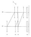
以下、本発明の各実施例を、添付図面に基づいて説明する。図1は、本実施例に係るズームレンズZLの屈折力配分及び広角端状態(W)から望遠端状態(T)への焦点距離状態の変化における各レンズ群の移動の様子を示す図である。この図1に示すように、本実施例に係るズームレンズZLは、物体側より順に、正の屈折力を有する第1レンズ群G1と、負の屈折力を有する第2レンズ群G2と、正の屈折力を有する第3レンズ群G3と、ローパスフィルターや赤外カットフィルター等からなるフィルター群FLとから構成されている。そして、広角端状態から望遠端状態までレンズ位置状態が変化する際に、少なくとも第1レンズ群G1及び第3レンズ群G3が物体側へ移動する。本実施例では、このように広角端状態から望遠端状態へのレンズ状態が変化する際に、第1レンズ群G1と第2レンズ群G2との間隔が増大し、第2レンズ群G2と第3レンズ群G3との間隔が減少するよう構成されている。 Embodiments of the present invention will be described below with reference to the accompanying drawings. FIG. 1 is a diagram illustrating a state of movement of each lens group in the refractive power distribution of the zoom lens ZL according to the present embodiment and the change in the focal length state from the wide-angle end state (W) to the telephoto end state (T). . As shown in FIG. 1, the zoom lens ZL according to the present embodiment includes, in order from the object side, a first lens group G1 having a positive refractive power, a second lens group G2 having a negative refractive power, And a third lens group G3 having a refractive power of 1 and a filter group FL including a low-pass filter and an infrared cut filter. When the lens position state changes from the wide-angle end state to the telephoto end state, at least the first lens group G1 and the third lens group G3 move to the object side. In the present embodiment, when the lens state changes from the wide-angle end state to the telephoto end state in this way, the distance between the first lens group G1 and the second lens group G2 increases, and the second lens group G2 and the second lens group G2 The distance from the third lens group G3 is reduced.
また、第4実施例において、非球面は、光軸に垂直な方向の高さをyとし、高さyにおける各非球面の頂点の接平面から各非球面までの光軸に沿った距離(サグ量)をS(y)、基準球面の曲率半径(近軸曲率半径)をrとし、円錐定数をκとし、n次の非球面係数をAnとしたとき、以下の数式(a)で表される。なお、以降に記載の第4実施例において、「E−n」は「×10−n」を示す In the fourth embodiment, the height of the aspheric surface in the direction perpendicular to the optical axis is y, and the distance along the optical axis from the tangent plane of each vertex of the aspheric surface to each aspheric surface at height y ( When the sag amount is S (y), the radius of curvature of the reference sphere (paraxial radius of curvature) is r, the conic constant is κ, and the nth-order aspherical coefficient is An, the following equation (a) is used. Is done. In the fourth embodiment described below, “E−n” indicates “× 10 −n ”.
S(y)=(y2/r)/{1+(1−κ×y2/r2)1/2}
+A4×y4+A6×y6+A8×y8+A10×y10 (a)
S (y) = (y 2 / r) / {1+ (1−κ × y 2 / r 2 ) 1/2 }
+ A4 × y 4 + A6 × y 6 + A8 × y 8 + A10 × y 10 (a)
なお、第4実施例において、2次の非球面係数A2は0である。また、第4実施例の表中において、非球面には、面番号の左側に*印を付している。 In the fourth embodiment, the secondary aspheric coefficient A2 is zero. Moreover, in the table | surface of 4th Example, * mark is attached | subjected to the left side of the surface number to the aspherical surface.
〔第1実施例〕
図2は、本発明の第1実施例にかかるズームレンズZL1の構成を示す図である。図2のズームレンズZL1において、第1レンズ群G1は、物体側から順に、第1a部分レンズ群G1a及び第1b部分レンズ群G1bから構成され、第1a部分レンズ群G1aは、物体側に凸面を向けた負メニスカスレンズL11と両凸レンズL11との貼り合わせからなる接合正レンズで構成され、第1b部分レンズ群G1bは、両凸レンズL13から構成されている。また、第2レンズ群G2は、物体側から順に、両凹レンズL21、両凹レンズL22と両凸レンズL23との貼り合わせからなる接合負レンズ、両凹レンズL24で構成されている。第3レンズ群G3は、物体側から順に、第3a部分レンズ群G3a及び第3b部分レンズ群G3bから構成され、第3a部分レンズ群G3aは、両凸レンズL31、両凸レンズL32と両凹レンズL33との貼り合わせからなる接合負レンズ、両凸レンズL34で構成され、第3b部分レンズ群G3bは、両凹レンズL35と両凸レンズL36との貼り合わせからなる接合負レンズ、物体側に凹面を向けた負メニスカスレンズL37で構成されている。さらに、フィルター群FLは、ローパスフィルターや赤外カットフィルター等から構成されている。
[First embodiment]
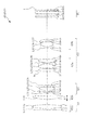
FIG. 2 is a diagram showing a configuration of the zoom lens ZL1 according to the first embodiment of the present invention. In the zoom lens ZL1 of FIG. 2, the first lens group G1 is composed of a 1a partial lens group G1a and a 1b partial lens group G1b in order from the object side, and the 1a partial lens group G1a has a convex surface on the object side. The first negative partial lens group G1b includes a biconvex lens L13. The cemented positive lens includes a negative meniscus lens L11 and a biconvex lens L11. The second lens group G2 includes, in order from the object side, a biconcave lens L21, a cemented negative lens formed by bonding the biconcave lens L22 and the biconvex lens L23, and a biconcave lens L24. The third lens group G3 includes, in order from the object side, a 3a partial lens group G3a and a 3b partial lens group G3b. The 3a partial lens group G3a includes a biconvex lens L31, a biconvex lens L32, and a biconcave lens L33. The third negative lens group G3b is composed of a cemented negative lens composed of a cemented lens and a biconvex lens L34. The third lens group G3b includes a cemented negative lens composed of a cemented biconvex lens L35 and a biconvex lens L36, and a negative meniscus lens having a concave surface facing the object side. L37. Further, the filter group FL includes a low-pass filter, an infrared cut filter, and the like.
像面Iは、不図示の撮像素子上に形成され、該撮像素子はCCDやCMOS等から構成されている(以降の実施例についても同様である。)。また、開口絞りSは、第3レンズ群G3の最も物体側に配置され、広角端状態から望遠端状態へのズーミングに際して第3レンズ群G3と一体に移動する。 The image plane I is formed on an image pickup device (not shown), and the image pickup device is composed of a CCD, a CMOS, or the like (the same applies to the following embodiments). The aperture stop S is disposed closest to the object side of the third lens group G3, and moves together with the third lens group G3 during zooming from the wide-angle end state to the telephoto end state.
次の表1に、第1実施例の諸元の値を掲げる。表1において、fは焦点距離を、F.NOはFナンバーを、2ωは画角を、Bfはバックフォーカスをそれぞれ表している。さらに、面番号は光線の進行する方向に沿った物体側からのレンズ面の順序を、屈折率及びアッベ数はそれぞれd線(λ=587.6nm)に対する値を示している。ここで、以下の全ての諸元値において掲載されている焦点距離f、曲率半径r、面間隔d、その他長さの単位は一般に「mm」が使われるが、光学系は、比例拡大または比例縮小しても同等の光学性能が得られるので、これに限られるものではない。尚、曲率半径0.0000は平面を示し、空気の屈折率1.00000は省略してある。なお、これらの符号の説明及び諸元表の説明は、以降の実施例においても同様である。 Table 1 below lists values of specifications of the first embodiment. In Table 1, f is the focal length, and F.I. NO represents the F number, 2ω represents the angle of view, and Bf represents the back focus. Further, the surface number indicates the order of the lens surfaces from the object side along the traveling direction of the light beam, and the refractive index and the Abbe number indicate values for the d-line (λ = 587.6 nm), respectively. Here, the focal length f, the radius of curvature r, the surface interval d, and other length units listed in all the following specification values are generally “mm”, but the optical system is proportionally enlarged or proportional. Since the same optical performance can be obtained even if the image is reduced, the present invention is not limited to this. The radius of curvature of 0.0000 indicates a plane, and the refractive index of air of 1.0000 is omitted. In addition, description of these codes | symbols and description of a specification table are the same also in a subsequent example.
(表1)
広角端 中間焦点距離 望遠端
f = 30.00 〜 65.50 〜 107.09
F.NO = 4.14 〜 4.85 〜 5.75
2ω = 31.89 〜 14.24 〜 8.79
像高 = 8.50 〜 8.50 〜 8.50
レンズ全長 = 76.00 〜 95.28 〜 105.00
面番号 曲率半径 面間隔 屈折率 アッベ数
1 280.8182 0.95 1.83400 37.16
2 51.9013 3.00 1.49782 82.52
3 -69.7458 4.20
4 39.2708 2.35 1.49782 82.52
5 -1873.4179 (d5)
6 -150.2667 0.80 1.69680 55.53
7 30.0997 0.85
8 -29.0467 0.80 1.69680 55.53
9 18.3923 2.20 1.84666 23.78
10 -166.9992 1.00
11 -20.5558 0.80 1.72916 54.68
12 4007.8031 (d12)
13 0.0000 0.50 (開口絞りS)
14 75.9842 2.15 1.60311 60.64
15 -23.7528 0.10
16 20.7865 3.30 1.49782 82.52
17 -15.5285 0.80 1.80384 33.89
18 77.1180 0.10
19 13.9597 2.70 1.60300 65.44
20 -83.0727 8.55
21 -29.0384 0.80 1.74400 44.79
22 6.7551 3.75 1.61293 37.00
23 -16.0409 0.85
24 -8.2498 1.15 1.78800 47.37
25 -13.8878 (d25)
26 0.0000 1.00 1.51680 64.12
27 0.0000 1.50
28 0.0000 1.87 1.51680 64.12
29 0.0000 0.40
30 0.0000 0.70 1.51680 64.12
31 0.0000 (Bf)
各レンズ群の焦点距離
群 始面 焦点距離
1 1 60.6470
2 6 -12.6602
3 14 14.7906
(Table 1)
Wide angle end Intermediate focal length Telephoto end
f = 30.00 to 65.50 to 107.09
F.NO = 4.14 to 4.85 to 5.75
2ω = 31.89 to 14.24 to 8.79
Image height = 8.50 to 8.50 to 8.50
Total lens length = 76.00 to 95.28 to 105.00
Surface number Curvature radius Surface spacing Refractive index Abbe number
1 280.8182 0.95 1.83400 37.16
2 51.9013 3.00 1.49782 82.52
3 -69.7458 4.20
4 39.2708 2.35 1.49782 82.52
5 -1873.4179 (d5)
6 -150.2667 0.80 1.69680 55.53
7 30.0997 0.85
8 -29.0467 0.80 1.69680 55.53
9 18.3923 2.20 1.84666 23.78
10 -166.9992 1.00
11 -20.5558 0.80 1.72916 54.68
12 4007.8031 (d12)
13 0.0000 0.50 (Aperture stop S)
14 75.9842 2.15 1.60311 60.64
15 -23.7528 0.10
16 20.7865 3.30 1.49782 82.52
17 -15.5285 0.80 1.80384 33.89
18 77.1180 0.10
19 13.9597 2.70 1.60300 65.44
20 -83.0727 8.55
21 -29.0384 0.80 1.74400 44.79
22 6.7551 3.75 1.61293 37.00
23 -16.0409 0.85
24 -8.2498 1.15 1.78800 47.37
25 -13.8878 (d25)
26 0.0000 1.00 1.51680 64.12
27 0.0000 1.50
28 0.0000 1.87 1.51680 64.12
29 0.0000 0.40
30 0.0000 0.70 1.51680 64.12
31 0.0000 (Bf)
Focal length group of each lens group Start surface Focal length
1 1 60.6470
2 6 -12.6602
3 14 14.7906
この第1実施例において、第1レンズ群G1と第2レンズ群G2との軸上空気間隔d5、第2レンズ群G2と第3レンズ群G3との軸上空気間隔d12、第3レンズ群G3とフィルター群FLとの軸上空気間隔d25、及びバックフォーカスBfは、ズーミングに際して変化する。次の表2に広角端状態、中間焦点距離状態、望遠端状態の各焦点距離における無限遠時の可変間隔を示す。 In the first embodiment, the axial air distance d5 between the first lens group G1 and the second lens group G2, the axial air distance d12 between the second lens group G2 and the third lens group G3, and the third lens group G3. The on-axis air distance d25 between the filter group FL and the back focus Bf changes during zooming. Table 2 below shows variable intervals at infinity at the respective focal lengths in the wide-angle end state, the intermediate focal length state, and the telephoto end state.
(表2)
広角端 中間焦点距離 望遠端
f 30.0001 65.5002 107.0904
d5 1.9728 19.9502 25.5252
d12 9.7735 5.1106 1.6047
d25 16.6581 22.6196 30.2744
Bf 0.5000 0.5001 0.5002
(Table 2)
Wide angle end Intermediate focal length Telephoto end
f 30.0001 65.5002 107.0904
d5 1.9728 19.9502 25.5252
d12 9.7735 5.1106 1.6047
d25 16.6581 22.6196 30.2744
Bf 0.5000 0.5001 0.5002
次の表3に、この第1実施例における各条件式対応値を示す。 Table 3 below shows values corresponding to the conditional expressions in the first embodiment.
(表3)
fw=30.0001
f1=60.6470
f1a=271.7971
f1b=77.2975
f2=-12.6602
f3=14.7906
(1)f1b/f1a=0.2844
(2)f1/fw=2.0216
(3)f1b/f1=1.2745
(4)f1/(−f2)=4.7904
(5)f1/f3=4.1004
(Table 3)
fw = 30.0001
f1 = 60.6470
f1a = 271.7971
f1b = 77.2975
f2 = -12.6602
f3 = 14.7906
(1) f1b / f1a = 0.2844
(2) f1 / fw = 2.0216
(3) f1b / f1 = 1.2745
( 4 ) f1 / (− f2) = 4.7904
( 5 ) f1 / f3 = 4.1004
図3は、d線(λ=587.6nm)に対する第1実施例の諸収差図である。すなわち、図3(a)は広角端状態(f=30.00mm)における無限遠合焦状態での諸収差図であり、図3(b)は中間焦点距離状態(f=65.50mm)における無限遠合焦状態での諸収差であり、図3(c)は望遠端状態(f=107.09mm)における無限遠合焦状態での諸収差である。 FIG. 3 is a diagram showing various aberrations of the first example with respect to the d-line (λ = 587.6 nm). 3A is a diagram showing various aberrations in the infinitely focused state in the wide-angle end state (f = 30.00 mm), and FIG. 3B is in the intermediate focal length state (f = 65.50 mm). FIG. 3C shows various aberrations in the infinite focus state in the telephoto end state (f = 107.09 mm).
各収差図において、FNOはFナンバーを、Aは各像高に対する半画角をそれぞれ示している。また、非点収差を示す収差図において実線はサジタル像面を示し、破線はメリディオナル像面を示している。なお、この収差図の説明は以降の実施例においても同様である。各収差図から明らかなように、第1実施例では、広角端状態から望遠端状態までの各焦点距離状態において諸収差が良好に補正され、優れた結像性能を有することがわかる。 In each aberration diagram, FNO represents an F number, and A represents a half angle of view with respect to each image height. In the aberration diagrams showing astigmatism, the solid line shows the sagittal image plane, and the broken line shows the meridional image plane. The description of this aberration diagram is the same in the following examples. As is apparent from the respective aberration diagrams, in the first embodiment, it is understood that various aberrations are well corrected in each focal length state from the wide-angle end state to the telephoto end state, and excellent imaging performance is obtained.
〔第2実施例〕
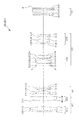
図4は、本発明の第2実施例に係るズームレンズZL2の構成を示す図である。この図4のズームレンズZL2において、第1レンズ群G1は、物体側から順に、第1a部分レンズ群G1a及び第1b部分レンズ群G1bから構成され、第1a部分レンズ群G1aは、物体側に凸面を向けた負メニスカスレンズL11と両凸レンズL12との貼り合わせからなる接合正レンズで構成され、第1b部分レンズ群G1bは、物体側に凸面を向けた正メニスカスレンズL13から構成されている。また、第2レンズ群G2は、物体側から順に、物体側に凹面を向けた正メニスカスレンズL21と両凹レンズL22との貼り合わせからなる接合負レンズ、物体側に凹面を向けた負メニスカスレンズL23で構成されている。第3レンズ群G3は、物体側から順に、第3a部分レンズ群G3a及び第3b部分レンズ群G3bから構成され、第3a部分レンズ群G3aは、物体側に凹面を向けた正メニスカスレンズL31、両凸レンズL32と両凹レンズL33との貼り合わせからなる接合正レンズ、両凸レンズL34から構成され、第3b部分レンズ群G3bは、両凹レンズL35と両凸レンズL36との貼り合わせからなる接合負レンズ、物体側に凹面を向けた負メニスカスレンズL37で構成されている。さらに、フィルター群FLは、ローパスフィルターや赤外カットフィルター等から構成されている。また、開口絞りSは、第3レンズ群G3の最も物体側に配置され、広角端状態から望遠端状態へのズーミングに際して第3レンズ群G3と一体に移動する。
[Second Embodiment]
FIG. 4 is a diagram showing a configuration of the zoom lens ZL2 according to the second embodiment of the present invention. In the zoom lens ZL2 of FIG. 4, the first lens group G1 is composed of a 1a partial lens group G1a and a 1b partial lens group G1b in order from the object side, and the 1a partial lens group G1a is convex on the object side. Is composed of a cemented positive lens formed by bonding a negative meniscus lens L11 and a biconvex lens L12, and the first-b partial lens group G1b is composed of a positive meniscus lens L13 having a convex surface facing the object side. The second lens group G2 includes, in order from the object side, a cemented negative lens formed by bonding a positive meniscus lens L21 having a concave surface facing the object side and a biconcave lens L22, and a negative meniscus lens L23 having a concave surface directed to the object side. It consists of The third lens group G3 includes, in order from the object side, a 3a partial lens group G3a and a 3b partial lens group G3b. The 3a partial lens group G3a includes a positive meniscus lens L31 having a concave surface facing the object side, It is composed of a cemented positive lens formed by bonding a convex lens L32 and a biconcave lens L33, and a biconvex lens L34. The third lens group G3b is a cemented negative lens formed by bonding a biconcave lens L35 and a biconvex lens L36. And a negative meniscus lens L37 having a concave surface facing the surface. Further, the filter group FL includes a low-pass filter, an infrared cut filter, and the like. The aperture stop S is disposed closest to the object side of the third lens group G3, and moves together with the third lens group G3 during zooming from the wide-angle end state to the telephoto end state.
次の表4に、この第2実施例の諸元の値を掲げる。 Table 4 below shows values of specifications of the second embodiment.
(表4)
広角端 中間焦点距離 望遠端
f = 30.00 〜 71.50 〜 107.09
F.NO = 4.21 〜 5.04 〜 5.68
2ω = 31.94 〜 13.08 〜 8.80
像高 = 8.50 〜 8.50 〜 8.50
レンズ全長 = 85.00 〜 100.37 〜 105.00
面番号 曲率半径 面間隔 屈折率 アッベ数
1 240.0450 0.95 1.83400 37.16
2 57.2707 3.00 1.49782 82.52
3 -78.0810 4.96
4 45.8457 3.39 1.49782 82.52
5 2463.4485 (d5)
6 -51.4985 1.78 1.84666 23.78
7 -17.8534 0.80 1.56384 60.66
8 28.7811 1.50
9 -16.9251 0.80 1.62041 60.29
10 -301.4407 (d10)
11 0.0000 0.50 (開口絞りS)
12 -401.0383 1.66 1.49700 81.54
13 -35.3632 0.10
14 25.0498 3.08 1.60300 65.44
15 -15.7224 0.80 1.80384 33.89
16 203.8341 0.33
17 17.4417 2.36 1.61800 63.33
18 -126.1678 9.45
19 -130.2123 0.80 1.83481 42.71
20 8.3229 3.10 1.62004 36.26
21 -21.3280 2.50
22 -10.0516 1.20 1.78800 47.37
23 -17.1063 (d23)
24 0.0000 1.00 1.51680 64.12
25 0.0000 1.50
26 0.0000 1.87 1.51680 64.12
27 0.0000 0.40
28 0.0000 0.70 1.51680 64.12
29 0.0000 (Bf)
各レンズ群の焦点距離
群 始面 焦点距離
1 1 69.0008
2 6 -17.7314
3 12 19.4587
(Table 4)
Wide angle end Intermediate focal length Telephoto end
f = 30.00 to 71.50 to 107.09
F.NO = 4.21 to 5.04 to 5.68
2ω = 31.94 to 13.08 to 8.80
Image height = 8.50 to 8.50 to 8.50
Total lens length = 85.00 to 100.37 to 105.00
Surface number Curvature radius Surface spacing Refractive index Abbe number
1 240.0450 0.95 1.83400 37.16
2 57.2707 3.00 1.49782 82.52
3 -78.0810 4.96
4 45.8457 3.39 1.49782 82.52
5 2463.4485 (d5)
6 -51.4985 1.78 1.84666 23.78
7 -17.8534 0.80 1.56384 60.66
8 28.7811 1.50
9 -16.9251 0.80 1.62041 60.29
10 -301.4407 (d10)
11 0.0000 0.50 (Aperture stop S)
12 -401.0383 1.66 1.49700 81.54
13 -35.3632 0.10
14 25.0498 3.08 1.60300 65.44
15 -15.7224 0.80 1.80384 33.89
16 203.8341 0.33
17 17.4417 2.36 1.61800 63.33
18 -126.1678 9.45
19 -130.2123 0.80 1.83481 42.71
20 8.3229 3.10 1.62004 36.26
21 -21.3280 2.50
22 -10.0516 1.20 1.78800 47.37
23 -17.1063 (d23)
24 0.0000 1.00 1.51680 64.12
25 0.0000 1.50
26 0.0000 1.87 1.51680 64.12
27 0.0000 0.40
28 0.0000 0.70 1.51680 64.12
29 0.0000 (Bf)
Focal length group of each lens group Start surface Focal length
1 1 69.0008
2 6 -17.7314
3 12 19.4587
この第2実施例において、第1レンズ群G1と第2レンズ群G2との軸上空気間隔d5、第2レンズ群G2と第3レンズ群G3との軸上空気間隔d10、第3レンズ群G3とフィルター群FLとの軸上空気間隔d23、及びバックフォーカスBfは、ズーミングに際して変化する。次の表5に広角端状態、中間焦点距離状態、望遠端状態の各焦点距離における可変間隔を示す。 In the second embodiment, the axial air distance d5 between the first lens group G1 and the second lens group G2, the axial air distance d10 between the second lens group G2 and the third lens group G3, and the third lens group G3. The on-axis air distance d23 between the filter group FL and the back focus Bf changes during zooming. Table 5 below shows variable intervals at the respective focal lengths in the wide-angle end state, the intermediate focal length state, and the telephoto end state.
(表5)
広角端 中間焦点距離 望遠端
f 30.0000 71.4999 107.0900
d5 2.8000 21.7359 26.5682
d10 17.4541 7.0722 1.5000
d23 15.7213 22.5407 27.9069
Bf 0.4999 0.5001 0.5002
(Table 5)
Wide angle end Intermediate focal length Telephoto end
f 30.0000 71.4999 107.0900
d5 2.8000 21.7359 26.5682
d10 17.4541 7.0722 1.5000
d23 15.7213 22.5407 27.9069
Bf 0.4999 0.5001 0.5002
次の表6に、この第2実施例における各条件式対応値を示す。 Table 6 below shows values corresponding to the conditional expressions in the second embodiment.
(表6)
fw=30.0000
f1=69.0008
f1a=249.4035
f1b=93.7955
f2=-17.7314
f3=19.4587
(1)f1b/f1a=0.3761
(2)f1/fw=2.3000
(3)f1b/f1=1.3593
(4)f1/(−f2)=3.8915
(5)f1/f3=3.5460
(Table 6)
fw = 30.0000
f1 = 69.0008
f1a = 249.4035
f1b = 93.7955
f2 = -17.7314
f3 = 19.4587
(1) f1b / f1a = 0.3761
(2) f1 / fw = 2.3000
(3) f1b / f1 = 1.593
(4) f1 / (− f2) = 3.8915
(5) f1 / f3 = 3.5460
図5は、d線(λ=587.6nm)に対する第2実施例の諸収差図である。すなわち、図5(a)は広角端状態(f=30.00mm)における無限遠合焦状態での諸収差図であり、図5(b)は中間焦点距離状態(f=71.50mm)における無限遠合焦状態での諸収差であり、図5(c)は望遠端状態(f=107.09mm)における無限遠合焦状態での諸収差である。各収差図から明らかなように、第2実施例では、広角端状態から望遠端状態までの各焦点距離状態において諸収差が良好に補正され、優れた結像性能を有することがわかる。 FIG. 5 is a diagram showing various aberrations of the second example with respect to the d-line (λ = 587.6 nm). That is, FIG. 5A is a diagram showing various aberrations in the infinite focus state in the wide-angle end state (f = 30.00 mm), and FIG. 5B is in the intermediate focal length state (f = 71.50 mm). FIG. 5C shows various aberrations in the infinite focus state in the telephoto end state (f = 107.09 mm). As is apparent from the respective aberration diagrams, in the second example, it is understood that various aberrations are favorably corrected in each focal length state from the wide-angle end state to the telephoto end state, and excellent imaging performance is obtained.
〔第3実施例〕
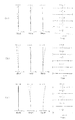
図6は、本発明の第3実施例にかかるズームレンズZL3の構成を示す図である。この図6のズームレンズZL3において、第1レンズ群G1は、物体側から順に、第1a部分レンズ群G1a及び第1b部分レンズ群G1bから構成され、第1a部分レンズ群G1aは、物体側に凸面を向けた負メニスカスレンズL11と両凸レンズL12との貼り合わせからなる接合正レンズで構成され、第1b部分レンズ群G1bは、両凸レンズL13から構成されている。また、第2レンズ群G2は、物体側から順に、両凹レンズL21、両凹レンズL22と両凸レンズL23との貼り合わせからなる接合負レンズ、両凹レンズL24で構成されている。第3レンズ群G3は、物体側から順に、第3a部分レンズ群G3a及び第3b部分レンズ群G3bから構成され、第3a部分レンズ群G3aは、両凸レンズL31、両凸レンズL32と両凹レンズL33との貼り合わせからなる接合正レンズ、両凸レンズL34で構成され、第3b部分レンズ群G3bは、両凹レンズL35と両凸レンズL36との貼り合わせからなる接合負レンズ、物体側に凹面を向けた負メニスカスレンズL37で構成されている。さらに、フィルター群FLは、ローパスフィルターや赤外カットフィルター等から構成されている。また、開口絞りSは、第3レンズ群G3の最も物体側に配置され、広角端状態から望遠端状態へのズーミングに際して第3レンズ群G3と一体に移動する。
[Third embodiment]
FIG. 6 is a diagram showing a configuration of a zoom lens ZL3 according to the third embodiment of the present invention. In the zoom lens ZL3 of FIG. 6, the first lens group G1 is composed of a 1a partial lens group G1a and a 1b partial lens group G1b in order from the object side, and the 1a partial lens group G1a is convex on the object side. Is composed of a cemented positive lens formed by bonding a negative meniscus lens L11 and a biconvex lens L12, and the first b partial lens group G1b is composed of a biconvex lens L13. The second lens group G2 includes, in order from the object side, a biconcave lens L21, a cemented negative lens formed by bonding the biconcave lens L22 and the biconvex lens L23, and a biconcave lens L24. The third lens group G3 includes, in order from the object side, a 3a partial lens group G3a and a 3b partial lens group G3b. The 3a partial lens group G3a includes a biconvex lens L31, a biconvex lens L32, and a biconcave lens L33. The third lens unit G3b is composed of a cemented positive lens composed of a cemented lens and a biconvex lens L34. The third lens group G3b includes a cemented negative lens composed of a cemented biconvex lens L35 and a biconvex lens L36, and a negative meniscus lens having a concave surface facing the object side. L37. Further, the filter group FL includes a low-pass filter, an infrared cut filter, and the like. The aperture stop S is disposed closest to the object side of the third lens group G3, and moves together with the third lens group G3 during zooming from the wide-angle end state to the telephoto end state.
次の表7に、この第3実施例の諸元の値を掲げる。 Table 7 below shows values of specifications of the third embodiment.
(表7)
広角端 中間焦点距離 望遠端
f = 29.54 〜 65.50 〜 107.09
F.NO = 4.11 〜 4.87 〜 5.77
2ω = 32.41 〜 14.23 〜 8.79
像高 = 8.50 〜 8.50 〜 8.50
レンズ全長 = 75.50 〜 95.08 〜 105.00
面番号 曲率半径 面間隔 屈折率 アッベ数
1 234.2875 0.95 1.83400 37.16
2 47.9733 3.00 1.49782 82.52
3 -67.6099 3.99
4 39.4608 2.40 1.49782 82.52
5 -1268.7397 (d5)
6 -118.4337 0.80 1.75500 52.32
7 35.2574 0.90
8 -38.6035 0.80 1.72000 50.23
9 14.0729 2.15 1.84666 23.78
10 -1793.3532 1.00
11 -19.9098 0.80 1.75500 52.32
12 287.2798 (d12)
13 0.0000 0.50 (開口絞りS)
14 130.0681 2.20 1.49782 82.52
15 -21.0703 0.10
16 25.0108 3.50 1.60300 65.44
17 -13.7558 0.80 1.80384 33.89
18 144.9113 0.10
19 13.1441 2.70 1.61800 63.33
20 -300.7928 7.20
21 -38.5116 0.80 1.80610 40.92
22 7.0874 3.50 1.62004 36.26
23 -15.7257 2.00
24 -8.3980 1.20 1.75500 52.32
25 -14.8336 (d25)
26 0.0000 1.00 1.51680 64.12
27 0.0000 1.50
28 0.0000 1.87 1.51680 64.12
29 0.0000 0.40
30 0.0000 0.70 1.51680 64.12
31 0.0000 (Bf)
各レンズ群の焦点距離
群 始面 焦点距離
1 1 59.4437
2 6 -12.0481
3 14 14.3179
(Table 7)
Wide angle end Intermediate focal length Telephoto end
f = 29.54 to 65.50 to 107.09
F.NO = 4.11 to 4.87 to 5.77
2ω = 32.41 to 14.23 to 8.79
Image height = 8.50 to 8.50 to 8.50
Total lens length = 75.50 to 95.08 to 105.00
Surface number Curvature radius Surface spacing Refractive index Abbe number
1 234.2875 0.95 1.83400 37.16
2 47.9733 3.00 1.49782 82.52
3 -67.6099 3.99
4 39.4608 2.40 1.49782 82.52
5 -1268.7397 (d5)
6 -118.4337 0.80 1.75500 52.32
7 35.2574 0.90
8 -38.6035 0.80 1.72000 50.23
9 14.0729 2.15 1.84666 23.78
10 -1793.3532 1.00
11 -19.9098 0.80 1.75500 52.32
12 287.2798 (d12)
13 0.0000 0.50 (Aperture stop S)
14 130.0681 2.20 1.49782 82.52
15 -21.0703 0.10
16 25.0108 3.50 1.60300 65.44
17 -13.7558 0.80 1.80384 33.89
18 144.9113 0.10
19 13.1441 2.70 1.61800 63.33
20 -300.7928 7.20
21 -38.5116 0.80 1.80610 40.92
22 7.0874 3.50 1.62004 36.26
23 -15.7257 2.00
24 -8.3980 1.20 1.75500 52.32
25 -14.8336 (d25)
26 0.0000 1.00 1.51680 64.12
27 0.0000 1.50
28 0.0000 1.87 1.51680 64.12
29 0.0000 0.40
30 0.0000 0.70 1.51680 64.12
31 0.0000 (Bf)
Focal length group of each lens group Start surface Focal length
1 1 59.4437
2 6 -12.0481
3 14 14.3179
この第3実施例において、第1レンズ群G1と第2レンズ群G2との軸上空気間隔d5、第2レンズ群G2と第3レンズ群G3との軸上空気間隔d12、第3レンズ群G3とフィルター群FLとの軸上空気間隔d25、及びバックフォーカスBfは、ズーミングに際して変化する。次の表8に広角端状態、中間焦点距離状態、望遠端状態の各焦点距離における無限遠時の可変間隔を示す。 In the third example, the axial air gap d5 between the first lens group G1 and the second lens group G2, the axial air gap d12 between the second lens group G2 and the third lens group G3, and the third lens group G3. The on-axis air distance d25 between the filter group FL and the back focus Bf changes during zooming. Table 8 below shows variable intervals at infinity at the respective focal lengths in the wide-angle end state, the intermediate focal length state, and the telephoto end state.
(表8)
広角端 中間焦点距離 望遠端
f 29.5364 65.4997 107.0894
d5 2.0000 19.6062 25.1011
d12 9.1910 4.7496 1.5000
d25 16.9515 23.3655 31.0414
Bf 0.4999 0.4999 0.4998
(Table 8)
Wide angle end Intermediate focal length Telephoto end
f 29.5364 65.4997 107.0894
d5 2.0000 19.6062 25.1011
d12 9.1910 4.7496 1.5000
d25 16.9515 23.3655 31.0414
Bf 0.4999 0.4999 0.4998
次の表9に、この第3実施例における各条件式対応値を示す。 Table 9 below shows values corresponding to the conditional expressions in the third embodiment.
(表9)
fw=29.5364
f1=59.4437
f1a=252.1944
f1b=76.9230
f2=-12.0481
f3=14.3179
(1)f1b/f1a=0.3050
(2)f1/fw=2.0126
(3)f1b/f1=1.2940
(3)f1/(−f2)=4.9339
(3)f1/f3=4.1517
(Table 9)
fw = 29.5364
f1 = 59.4437
f1a = 252.1944
f1b = 76.9230
f2 = -12.0481
f3 = 14.3179
(1) f1b / f1a = 0.050
(2) f1 / fw = 2.0126
(3) f1b / f1 = 1.2940
(3) f1 / (− f2) = 4.9339
(3) f1 / f3 = 4.1517
図7は、d線(λ=587.6nm)に対する第3実施例の諸収差図である。すなわち、図7(a)は広角端状態(f=29.54mm)における無限遠合焦状態での諸収差図であり、図7(b)は中間焦点距離状態(f=65.50mm)における無限遠合焦状態での諸収差であり、図7(c)は望遠端状態(f=107.09mm)における無限遠合焦状態での諸収差である。各収差図から明らかなように、第3実施例では、広角端状態から望遠端状態までの各焦点距離状態において諸収差が良好に補正され、優れた結像性能を有することがわかる。 FIG. 7 is a diagram showing various aberrations of the third example with respect to the d-line (λ = 587.6 nm). 7A is a diagram showing various aberrations in the infinitely focused state in the wide-angle end state (f = 29.54 mm), and FIG. 7B is a diagram in the intermediate focal length state (f = 65.50 mm). FIG. 7C shows various aberrations in the infinity in-focus state in the telephoto end state (f = 107.09 mm). As is apparent from the respective aberration diagrams, in the third example, it is understood that various aberrations are favorably corrected in each focal length state from the wide-angle end state to the telephoto end state, and excellent imaging performance is obtained.
〔第4実施例〕
図8は、本発明の第4実施例にかかるズームレンズZL4の構成を示す図である。図8のズームレンズZL4において、第1レンズ群G1は、物体側から順に、第1a部分レンズ群G1a及び第1b部分レンズ群G1bから構成され、第1a部分レンズ群G1aは、物体側に凸面を向けた負メニスカスレンズL11と両凸レンズL12との貼り合わせからなる接合正レンズで構成され、第1b部分レンズ群G1bは、両凸レンズL13から構成されている。また、第2レンズ群G2は、物体側から順に、両凹レンズL21、両凹レンズL22と像側に凹面を向けた負メニスカスレンズL23との貼り合わせからなる接合負レンズ、両凹レンズL24で構成されている。第3レンズ群G3は、物体側から順に、第3a部分レンズ群G3a及び第3b部分レンズ群G3bから構成され、第3a部分レンズ群G3aは、両凸レンズL31、両凸レンズL32と両凹レンズL33との貼り合わせからなる接合負レンズ、両凸レンズL34から構成され、第3b部分レンズ群G3bは、両凹レンズL35と両凸レンズL36との貼り合わせからなる接合負レンズ、物体側に凹面を向けた負メニスカスレンズL37で構成されている。さらに、フィルター群FLは、ローパスフィルターや赤外カットフィルター等から構成されている。また、開口絞りSは、第3レンズ群G3の最も物体側に配置され、広角端状態から望遠端状態へのズーミングに際して第3レンズ群G3と一体に移動する。
[Fourth embodiment]
FIG. 8 is a diagram showing a configuration of a zoom lens ZL4 according to the fourth embodiment of the present invention. In the zoom lens ZL4 of FIG. 8, the first lens group G1 is composed of a 1a partial lens group G1a and a 1b partial lens group G1b in order from the object side, and the 1a partial lens group G1a has a convex surface on the object side. The first negative partial lens group G1b is composed of a biconvex lens L13. The cemented positive lens is formed by bonding a negative meniscus lens L11 and a biconvex lens L12. The second lens group G2 is composed of, in order from the object side, a biconcave lens L21, a cemented negative lens formed by bonding a biconcave lens L22 and a negative meniscus lens L23 having a concave surface facing the image side, and a biconcave lens L24. Yes. The third lens group G3 includes, in order from the object side, a 3a partial lens group G3a and a 3b partial lens group G3b. The 3a partial lens group G3a includes a biconvex lens L31, a biconvex lens L32, and a biconcave lens L33. The third negative lens group G3b is composed of a cemented negative lens composed of a cemented lens and a biconvex lens L34. The third lens group G3b includes a cemented negative lens composed of a cemented biconvex lens L35 and a biconvex lens L36, and a negative meniscus lens having a concave surface facing the object side. L37. Further, the filter group FL includes a low-pass filter, an infrared cut filter, and the like. The aperture stop S is disposed closest to the object side of the third lens group G3, and moves together with the third lens group G3 during zooming from the wide-angle end state to the telephoto end state.
次の表10に、この第4実施例の諸元の値を掲げる。 Table 10 below shows values of specifications of the fourth embodiment.
(表10)
広角端 中間焦点距離 望遠端
f = 30.00 〜 65.50 〜 107.09
F.NO = 4.10 〜 4.80 〜 5.66
2ω = 31.94 〜 14.24 〜 8.79
像高 = 8.50 〜 8.50 〜 8.50
レンズ全長 = 74.85 〜 94.77 〜 104.64
面番号 曲率半径 面間隔 屈折率 アッベ数
1 193.2233 0.95 1.83400 37.16
2 47.3650 3.00 1.49782 82.52
3 -75.6262 4.20
4 42.0254 2.37 1.49782 82.52
5 -578.3692 (d5)
6 -94.6162 0.80 1.69680 55.53
7 34.4303 0.87
8 -43.1620 0.80 1.69680 55.53
9 14.6962 2.05 1.84666 23.78
10 184.3492 1.00
11 -20.2434 0.80 1.72916 54.68
12 278.2271 (d12)
13 0.0000 0.50 (開口絞りS)
*14 45.2942 2.31 1.59201 67.02
15 -24.2906 0.10
16 16.7868 3.15 1.49700 81.54
17 -21.5682 0.80 1.80384 33.89
18 29.0872 0.10
19 14.9282 2.70 1.61800 63.33
20 -59.7605 7.84
21 -51.0971 0.80 1.74400 44.79
22 7.1372 3.29 1.61293 37.00
23 -26.5759 2.50
24 -8.0713 1.01 1.75500 52.32
25 -11.6918 (d25)
26 0.0000 1.00 1.51680 64.12
27 0.0000 1.50
28 0.0000 1.87 1.51680 64.12
29 0.0000 0.40
30 0.0000 0.70 1.51680 64.12
31 0.0000 (Bf)
各レンズ群の焦点距離
群 始面 焦点距離
1 1 61.1194
2 6 -12.1826
3 14 14.2210
(Table 10)
Wide angle end Intermediate focal length Telephoto end
f = 30.00 to 65.50 to 107.09
F.NO = 4.10 to 4.80 to 5.66
2ω = 31.94 to 14.24 to 8.79
Image height = 8.50 to 8.50 to 8.50
Total lens length = 74.85 to 94.77 to 104.64
Surface number Curvature radius Surface spacing Refractive index Abbe number
1 193.2233 0.95 1.83400 37.16
2 47.3650 3.00 1.49782 82.52
3 -75.6262 4.20
4 42.0254 2.37 1.49782 82.52
5 -578.3692 (d5)
6 -94.6162 0.80 1.69680 55.53
7 34.4303 0.87
8 -43.1620 0.80 1.69680 55.53
9 14.6962 2.05 1.84666 23.78
10 184.3492 1.00
11 -20.2434 0.80 1.72916 54.68
12 278.2271 (d12)
13 0.0000 0.50 (Aperture stop S)
* 14 45.2942 2.31 1.59201 67.02
15 -24.2906 0.10
16 16.7868 3.15 1.49700 81.54
17 -21.5682 0.80 1.80384 33.89
18 29.0872 0.10
19 14.9282 2.70 1.61800 63.33
20 -59.7605 7.84
21 -51.0971 0.80 1.74400 44.79
22 7.1372 3.29 1.61293 37.00
23 -26.5759 2.50
24 -8.0713 1.01 1.75500 52.32
25 -11.6918 (d25)
26 0.0000 1.00 1.51680 64.12
27 0.0000 1.50
28 0.0000 1.87 1.51680 64.12
29 0.0000 0.40
30 0.0000 0.70 1.51680 64.12
31 0.0000 (Bf)
Focal length group of each lens group Start surface Focal length
1 1 61.1194
2 6 -12.1826
3 14 14.2210
この第4実施例において、第14面は非球面形状に形成されている。次の表11に、非球面のデータ、すなわち頂点曲率半径R、円錐定数κ及び各非球面定数A4〜A10の値を示す。 In the fourth embodiment, the fourteenth surface is formed in an aspherical shape. Table 11 below shows the data of the aspheric surface, that is, the values of the vertex curvature radius R, the conic constant κ, and the aspheric constants A4 to A10.
(表11)
〔第14面〕
R κ A4 A6 A8 A10
45.2942 -6.9268 -1.1290E-5 -7.6188E-8 +1.4298E-9 -1.7925E-11
(Table 11)
[14th page]
R κ A4 A6 A8 A10
45.2942 -6.9268 -1.1290E-5 -7.6188E-8 + 1.4298E-9 -1.7925E-11
この第4実施例において、第1レンズ群G1と第2レンズ群G2との軸上空気間隔d5、第2レンズ群G2と第3レンズ群G3との軸上空気間隔d12、第3レンズ群G3とフィルター群FLとの軸上空気間隔d25、及びバックフォーカスBfは、ズーミングに際して変化する。次の表12に広角端状態、中間焦点距離状態、望遠端状態の各焦点距離における可変間隔を示す。 In the fourth embodiment, the axial air distance d5 between the first lens group G1 and the second lens group G2, the axial air distance d12 between the second lens group G2 and the third lens group G3, and the third lens group G3. The on-axis air distance d25 between the filter group FL and the back focus Bf changes during zooming. Table 12 below shows variable intervals at each focal length in the wide-angle end state, the intermediate focal length state, and the telephoto end state.
(表12)
広角端 中間焦点距離 望遠端
f 30.0000 65.4998 107.0895
d5 2.0000 20.2978 26.0910
d12 9.0187 4.7480 1.5000
d25 15.9456 21.8209 29.1420
Bf 0.4912 0.5021 0.5108
(Table 12)
Wide angle end Intermediate focal length Telephoto end
f 30.0000 65.4998 107.0895
d5 2.0000 20.2978 26.0910
d12 9.0187 4.7480 1.5000
d25 15.9456 21.8209 29.1420
Bf 0.4912 0.5021 0.5108
次の表13に、この第4実施例における各条件式対応値を示す。 Table 13 below shows values corresponding to the conditional expressions in the fourth embodiment.
(表13)
fw=30.0001
f1=61.1194
f1a=260.4946
f1b=78.8004
f2=-12.1826
f3=14.2210
(1)f1b/f1a=0.3025
(2)f1/fw=2.0373
(3)f1b/f1=1.2893
(4)f1/(−f2)=5.0169
(5)f1/f3=4.2978
(Table 13)
fw = 30.0001
f1 = 61.1194
f1a = 260.4946
f1b = 78.8004
f2 = -12.1826
f3 = 14.2210
(1) f1b / f1a = 0.3025
(2) f1 / fw = 2.0373
(3) f1b / f1 = 1.2893
(4) f1 / (− f2) = 5.0169
(5) f1 / f3 = 4.2978
図9は、d線(λ=587.6nm)に対する第4実施例の諸収差図である。すなわち、図9(a)は広角端状態(f=30.00mm)における無限遠合焦状態での諸収差図であり、図9(b)は中間焦点距離状態(f=65.50mm)における無限遠合焦状態での諸収差であり、図9(c)は望遠端状態(f=107.09mm)における無限遠合焦状態での諸収差である。各収差図から明らかなように、第4実施例では、広角端状態から望遠端状態までの各焦点距離状態において諸収差が良好に補正され、優れた結像性能を有することがわかる。 FIG. 9 is a diagram of various aberrations of the fourth example for the d-line (λ = 587.6 nm). That is, FIG. 9A is a diagram of various aberrations in the infinite focus state in the wide-angle end state (f = 30.00 mm), and FIG. 9B is the intermediate focal length state (f = 65.50 mm). FIG. 9C shows various aberrations in the infinity in-focus state in the telephoto end state (f = 107.09 mm). As is apparent from the respective aberration diagrams, in the fourth example, it is understood that various aberrations are favorably corrected in each focal length state from the wide-angle end state to the telephoto end state, and excellent imaging performance is obtained.
〔第5実施例〕
図10は、本発明の第5実施例にかかるズームレンズZL5の構成を示す図である。図10のズームレンズZL5において、第1レンズ群G1は、物体側から順に、第1a部分レンズ群G1a及び第1b部分レンズ群G1bから構成され、第1a部分レンズ群G1aは、両凸レンズL11で構成され、第1b部分レンズ群G1bは、物体側に凹面を向けた負メニスカスレンズL12と両凸レンズL13との貼り合わせからなる接合負レンズから構成されている。また、第2レンズ群G2は、物体側から順に、物体側に凸面を向けた負メニスカスレンズL21、両凹レンズL22と両凸レンズL23との貼り合わせからなる接合負レンズ、物体側に凹面を向けた負メニスカスレンズL24で構成されている。第3レンズ群G3は、物体側から順に、第3a部分レンズ群G3a及び第3b部分レンズ群G3bから構成され、第3a部分レンズ群G3aは、両凸レンズL31、両凸レンズL32と両凹レンズL33との貼り合わせからなる接合負レンズ、両凸レンズL34から構成され、第3b部分レンズ群G3bは、両凹レンズL35と両凸レンズL36との貼り合わせからなる接合負レンズ、物体側に凹面を向けた負メニスカスレンズL37で構成されている。さらに、フィルター群FLは、ローパスフィルターや赤外カットフィルター等から構成されている。また、開口絞りSは、第3レンズ群G3の最も物体側に配置され、広角端状態から望遠端状態へのズーミングに際して第3レンズ群G3と一体に移動する。
[Fifth embodiment]
FIG. 10 is a diagram showing a configuration of a zoom lens ZL5 according to the fifth embodiment of the present invention. In the zoom lens ZL5 of FIG. 10, the first lens group G1 is composed of a 1a partial lens group G1a and a 1b partial lens group G1b in order from the object side, and the 1a partial lens group G1a is composed of a biconvex lens L11. The first-b partial lens group G1b is composed of a cemented negative lens formed by bonding a negative meniscus lens L12 having a concave surface facing the object side and a biconvex lens L13. The second lens group G2, in order from the object side, has a negative meniscus lens L21 having a convex surface facing the object side, a cemented negative lens formed by bonding the biconcave lens L22 and the biconvex lens L23, and a concave surface facing the object side. It is composed of a negative meniscus lens L24. The third lens group G3 includes, in order from the object side, a 3a partial lens group G3a and a 3b partial lens group G3b. The 3a partial lens group G3a includes a biconvex lens L31, a biconvex lens L32, and a biconcave lens L33. The third negative lens group G3b is composed of a cemented negative lens composed of a cemented lens and a biconvex lens L34. The third lens group G3b includes a cemented negative lens composed of a cemented biconvex lens L35 and a biconvex lens L36, and a negative meniscus lens having a concave surface facing the object side. L37. Further, the filter group FL includes a low-pass filter, an infrared cut filter, and the like. The aperture stop S is disposed closest to the object side of the third lens group G3, and moves together with the third lens group G3 during zooming from the wide-angle end state to the telephoto end state.
次の表14に、この第5実施例の諸元の値を掲げる。 Table 14 below lists values of specifications of the fifth embodiment.
(表14)
広角端 中間焦点距離 望遠端
f = 30.00 〜 65.50 〜 107.09
F.NO = 4.11 〜 4.72 〜 5.63
2ω = 31.94 〜 14.25 〜 8.79
像高 = 8.50 〜 8.50 〜 8.50
レンズ全長 = 75.50 〜 95.02 〜 104.52
面番号 曲率半径 面間隔 屈折率 アッベ数
1 227.3101 1.62 1.51680 64.10
2 -227.3101 4.72
3 39.0309 0.80 1.78470 26.29
4 27.4849 3.00 1.49782 82.52
5 -296.1941 (d5)
6 176.0290 0.80 1.69680 55.53
7 23.2355 1.15
8 -31.8792 0.80 1.69680 55.53
9 18.2337 1.96 1.84666 23.78
10 -194.3960 1.00
11 -17.4270 0.80 1.72916 54.68
12 -262.9406 (d12)
13 0.0000 0.50 (開口絞りS)
14 148.4542 2.17 1.60300 65.44
15 -21.3098 0.10
16 21.4676 3.22 1.49700 81.54
17 -15.4535 0.80 1.80384 33.89
18 86.3565 0.10
19 14.5468 2.70 1.61800 63.33
20 -94.3058 8.91
21 -30.7082 0.89 1.74400 44.79
22 7.2820 3.50 1.61293 37.00
23 -16.5601 1.29
24 -8.4090 1.01 1.75500 52.32
25 -13.6611 (d25)
26 0.0000 1.00 1.51680 64.12
27 0.0000 1.50
28 0.0000 1.87 1.51680 64.12
29 0.0000 0.40
30 0.0000 0.70 1.51680 64.12
31 0.0000 (Bf)
各レンズ群の焦点距離
群 始面 焦点距離
1 1 63.8324
2 6 -12.6553
3 14 14.8909
(Table 14)
Wide angle end Intermediate focal length Telephoto end
f = 30.00 to 65.50 to 107.09
F.NO = 4.11 to 4.72 to 5.63
2ω = 31.94-14.25-8.79
Image height = 8.50 to 8.50 to 8.50
Total lens length = 75.50 to 95.02 to 104.52
Surface number Curvature radius Surface spacing Refractive index Abbe number
1 227.3101 1.62 1.51680 64.10
2 -227.3101 4.72
3 39.0309 0.80 1.78470 26.29
4 27.4849 3.00 1.49782 82.52
5 -296.1941 (d5)
6 176.0290 0.80 1.69680 55.53
7 23.2355 1.15
8 -31.8792 0.80 1.69680 55.53
9 18.2337 1.96 1.84666 23.78
10 -194.3960 1.00
11 -17.4270 0.80 1.72916 54.68
12 -262.9406 (d12)
13 0.0000 0.50 (Aperture stop S)
14 148.4542 2.17 1.60300 65.44
15 -21.3098 0.10
16 21.4676 3.22 1.49700 81.54
17 -15.4535 0.80 1.80384 33.89
18 86.3565 0.10
19 14.5468 2.70 1.61800 63.33
20 -94.3058 8.91
21 -30.7082 0.89 1.74400 44.79
22 7.2820 3.50 1.61293 37.00
23 -16.5601 1.29
24 -8.4090 1.01 1.75500 52.32
25 -13.6611 (d25)
26 0.0000 1.00 1.51680 64.12
27 0.0000 1.50
28 0.0000 1.87 1.51680 64.12
29 0.0000 0.40
30 0.0000 0.70 1.51680 64.12
31 0.0000 (Bf)
Focal length group of each lens group Start surface Focal length
1 1 63.8324
2 6 -12.6553
3 14 14.8909
この第5実施例において、第1レンズ群G1と第2レンズ群G2との軸上空気間隔d5、第2レンズ群G2と第3レンズ群G3との軸上空気間隔d12、第3レンズ群G3とフィルタ群FLとの軸上空気間隔d25、及びバックフォーカスBfは、ズーミングに際して変化する。次の表15に広角端状態、中間焦点距離状態、望遠端状態の各焦点距離における無限遠時の可変間隔を示す。 In the fifth embodiment, the axial air distance d5 between the first lens group G1 and the second lens group G2, the axial air distance d12 between the second lens group G2 and the third lens group G3, and the third lens group G3. The on-axis air gap d25 between the filter group FL and the back focus Bf changes during zooming. Table 15 below shows variable intervals at infinity at the respective focal lengths in the wide-angle end state, the intermediate focal length state, and the telephoto end state.
(表15)
広角端 中間焦点距離 望遠端
f 30.0001 65.5003 107.0906
d5 2.0000 20.6855 20.3023
d12 9.6995 5.0515 1.5000
d25 15.9954 21.4733 28.9089
Bf 0.5001 0.5002 0.5002
(Table 15)
Wide angle end Intermediate focal length Telephoto end
f 30.0001 65.5003 107.0906
d5 2.0000 20.6855 20.3023
d12 9.6995 5.0515 1.5000
d25 15.9954 21.4733 28.9089
Bf 0.5001 0.5002 0.5002
次の表16に、この第5実施例における各条件式対応値を示す。 Table 16 below shows values corresponding to the conditional expressions in the fifth embodiment.
(表16)
fw=30.0001
f1=63.8324
f1a=220.1876
f1b=87.7682
f2=-12.6553
f3=14.8909
(1)f1b/f1a=0.3986
(2)f1/fw=2.1277
(3)f1b/f1=1.3750
(4)f1/(−f2)=5.0439
(5)f1/f3=4.2867
(Table 16)
fw = 30.0001
f1 = 63.8324
f1a = 220.1876
f1b = 87.7682
f2 = -12.6553
f3 = 14.8909
(1) f1b / f1a = 0.3986
(2) f1 / fw = 2.1277
(3) f1b / f1 = 1.3750
(4) f1 / (− f2) = 5.0439
(5) f1 / f3 = 4.2867
図11は、d線(λ=587.6nm)に対する第5実施例の諸収差図である。すなわち、図11(a)は広角端状態(f=30.00mm)における無限遠合焦状態での諸収差図であり、図11(b)は中間焦点距離状態(f=65.50mm)における無限遠合焦状態での諸収差であり、図11(c)は望遠端状態(f=107.09mm)における無限遠合焦状態での諸収差である。各収差図から明らかなように、第5実施例では、広角端状態から望遠端状態までの各焦点距離状態において諸収差が良好に補正され、優れた結像性能を有することがわかる。 FIG. 11 is a diagram illustrating various aberrations of the fifth example with respect to the d-line (λ = 587.6 nm). That is, FIG. 11A is a diagram of various aberrations in the infinitely focused state in the wide-angle end state (f = 30.00 mm), and FIG. 11B is the intermediate focal length state (f = 65.50 mm). FIG. 11C shows various aberrations in the infinity in-focus state in the telephoto end state (f = 107.09 mm). As is apparent from each aberration diagram, in the fifth example, it is understood that various aberrations are well corrected in each focal length state from the wide-angle end state to the telephoto end state, and excellent imaging performance is obtained.
〔第6実施例〕
図12は、本発明の第6実施例にかかるズームレンズZL6の構成を示す図である。図12のズームレンズZL6において、第1レンズ群G1は、物体側から順に、第1a部分レンズ群G1a及び第1b部分レンズ群G1bから構成され、第1a部分レンズ群G1aは、物体側に凸面を向けた負メニスカスレンズL11と両凸レンズL12との貼り合わせからなる接合正レンズで構成され、第1b部分レンズ群G1bは、物体側に凸面を向けた正メニスカスレンズL13から構成されている。また、第2レンズ群G2は、物体側から順に、物体側に凹面を向けた負メニスカスレンズL21と両凹レンズL22との貼り合わせからなる接合負レンズ、物体側に凹面を向けた負メニスカスレンズL23で構成されている。第3レンズ群G3は、物体側から順に、第3a部分レンズ群G3a及び第3b部分レンズ群G3bから構成され、第3a部分レンズ群G3aは、両凸レンズL31、両凸レンズL32と両凹レンズL33との貼り合わせからなる接合正レンズ、両凸レンズL34から構成され、第3a部分レンズ群G3aは、両凹レンズL35と両凸レンズL36との貼り合わせからなる接合負レンズ、物体側に凹面を向けた負メニスカスレンズL37で構成されている。さらに、フィルター群FLは、ローパスフィルターや赤外カットフィルター等から構成されている。また、開口絞りSは、第3レンズ群G3の最も物体側に配置され、広角端状態から望遠端状態へのズーミングに際して第3レンズ群G3と一体に移動する。
[Sixth embodiment]
FIG. 12 is a diagram showing a configuration of a zoom lens ZL6 according to the sixth embodiment of the present invention. In the zoom lens ZL6 of FIG. 12, the first lens group G1 is composed of a 1a partial lens group G1a and a 1b partial lens group G1b in this order from the object side, and the 1a partial lens group G1a has a convex surface on the object side. The first negative partial lens group G1b is composed of a positive meniscus lens L13 having a convex surface facing the object side. The negative positive meniscus lens L11 and a biconvex lens L12 are bonded to each other. The second lens group G2 includes, in order from the object side, a cemented negative lens formed by bonding a negative meniscus lens L21 having a concave surface facing the object side and a biconcave lens L22, and a negative meniscus lens L23 having a concave surface directed to the object side. It consists of The third lens group G3 includes, in order from the object side, a 3a partial lens group G3a and a 3b partial lens group G3b. The 3a partial lens group G3a includes a biconvex lens L31, a biconvex lens L32, and a biconcave lens L33. The 3a partial lens group G3a is composed of a cemented positive lens composed of a cemented lens and a biconvex lens L34, and is composed of a cemented negative lens composed of a cemented biconvex lens L35 and a biconvex lens L36, and a negative meniscus lens having a concave surface facing the object side. L37. Further, the filter group FL includes a low-pass filter, an infrared cut filter, and the like. The aperture stop S is disposed closest to the object side of the third lens group G3, and moves together with the third lens group G3 during zooming from the wide-angle end state to the telephoto end state.
次の表17に、この第6実施例の諸元の値を掲げる。 Table 17 below shows values of specifications of the sixth embodiment.
(表17)
広角端 中間焦点距離 望遠端
f = 30.00 〜 66.44 〜 107.09
F.NO = 4.16 〜 4.89 〜 5.68
2ω = 31.94 〜 14.05 〜 8.79
像高 = 8.50 〜 8.50 〜 8.50
レンズ全長 = 75.00 〜 95.74 〜 105.00
面番号 曲率半径 面間隔 屈折率 アッベ数
1 273.7117 0.95 1.83400 37.16
2 55.6806 3.00 1.49782 82.52
3 -68.2296 4.57
4 40.7804 2.21 1.49782 82.52
5 389.8809 (d5)
6 -37.6582 1.92 1.84666 23.78
7 -13.8724 0.80 1.56384 60.66
8 24.1738 1.69
9 -13.0806 0.80 1.62041 60.29
10 -322.7438 (d10)
11 0.0000 0.50 (開口絞りS)
12 48.0311 2.08 1.49700 81.54
13 -33.8610 0.10
14 26.7689 3.28 1.60300 65.44
15 -12.8497 0.80 1.80384 33.89
16 339.1966 0.10
17 14.2282 2.70 1.61800 63.33
18 -74.4328 6.70
19 -60.3246 0.80 1.83481 42.71
20 6.9024 3.50 1.62004 36.26
21 -15.8495 1.20
22 -8.8529 1.20 1.78800 47.37
23 -16.7933 (d23)
24 0.0000 1.00 1.51680 64.12
25 0.0000 1.50
26 0.0000 1.87 1.51680 64.12
27 0.0000 0.40
28 0.0000 0.70 1.51680 64.12
29 0.0000 (Bf)
各レンズ群の焦点距離
群 始面 焦点距離
1 1 66.0533
2 6 -13.5128
3 12 15.2087
(Table 17)
Wide angle end Intermediate focal length Telephoto end
f = 30.00 to 66.44 to 107.09
F.NO = 4.16 to 4.89 to 5.68
2ω = 31.94-14.05-8.79
Image height = 8.50 to 8.50 to 8.50
Total lens length = 75.00 to 95.74 to 105.00
Surface number Curvature radius Surface spacing Refractive index Abbe number
1 273.7117 0.95 1.83400 37.16
2 55.6806 3.00 1.49782 82.52
3 -68.2296 4.57
4 40.7804 2.21 1.49782 82.52
5 389.8809 (d5)
6 -37.6582 1.92 1.84666 23.78
7 -13.8724 0.80 1.56384 60.66
8 24.1738 1.69
9 -13.0806 0.80 1.62041 60.29
10 -322.7438 (d10)
11 0.0000 0.50 (Aperture stop S)
12 48.0311 2.08 1.49700 81.54
13 -33.8610 0.10
14 26.7689 3.28 1.60300 65.44
15 -12.8497 0.80 1.80384 33.89
16 339.1966 0.10
17 14.2282 2.70 1.61800 63.33
18 -74.4328 6.70
19 -60.3246 0.80 1.83481 42.71
20 6.9024 3.50 1.62004 36.26
21 -15.8495 1.20
22 -8.8529 1.20 1.78800 47.37
23 -16.7933 (d23)
24 0.0000 1.00 1.51680 64.12
25 0.0000 1.50
26 0.0000 1.87 1.51680 64.12
27 0.0000 0.40
28 0.0000 0.70 1.51680 64.12
29 0.0000 (Bf)
Focal length group of each lens group Start surface Focal length
1 1 66.0533
2 6 -13.5128
3 12 15.2087
この第6実施例において、第1レンズ群G1と第2レンズ群G2との軸上空気間隔d5、第2レンズ群G2と第3レンズ群G3との軸上空気間隔d10、第3レンズ群G3とフィルター群FLとの軸上空気間隔d23、及びバックフォーカスBfは、ズーミングに際して変化する。次の表18に広角端状態、中間焦点距離状態、望遠端状態の各焦点距離における無限遠時の可変間隔を示す。 In the sixth example, the axial air distance d5 between the first lens group G1 and the second lens group G2, the axial air distance d10 between the second lens group G2 and the third lens group G3, and the third lens group G3. The on-axis air distance d23 between the filter group FL and the back focus Bf changes during zooming. Table 18 below shows variable intervals at infinity at the respective focal lengths in the wide-angle end state, the intermediate focal length state, and the telephoto end state.
(表18)
広角端 中間焦点距離 望遠端
f 29.9999 66.4434 107.0887
d5 2.0000 21.6530 27.9021
d10 10.2160 5.1472 1.5000
d23 17.9247 24.0759 30.7380
Bf 0.4998 0.4999 0.4999
(Table 18)
Wide angle end Intermediate focal length Telephoto end
f 29.9999 66.4434 107.0887
d5 2.0000 21.6530 27.9021
d10 10.2160 5.1472 1.5000
d23 17.9247 24.0759 30.7380
Bf 0.4998 0.4999 0.4999
次の表19に、この第6実施例における各条件式対応値を示す。 Table 19 below shows values corresponding to the conditional expressions in the sixth embodiment.
(表19)
fw=29.9999
f1=66.0533
f1a=230.0345
f1b=91.2951
f2=-13.5128
f3=15.2087
(1)f1b/f1a=0.3969
(2)f1/fw=2.2018
(3)f1b/f1=1.3821
(4)f1/(−f2)=4.8882
(5)f1/f3=4.3431
(Table 19)
fw = 29.9999
f1 = 66.0533
f1a = 230.0345
f1b = 91.2951
f2 = -13.5128
f3 = 15.2087
(1) f1b / f1a = 0.3969
(2) f1 / fw = 2.2018
(3) f1b / f1 = 1.3821
(4) f1 / (− f2) = 4.8882
(5) f1 / f3 = 4.3431
図13は、d線(λ=587.6nm)に対する第6実施例の諸収差図である。すなわち、図13(a)は広角端状態(f=30.00mm)における無限遠合焦状態での諸収差図であり、図13(b)は中間焦点距離状態(f=66.44mm)における無限遠合焦状態での諸収差であり、図13(c)は望遠端状態(f=107.09mm)における無限遠合焦状態での諸収差である。各収差図から明らかなように、第6実施例では、広角端状態から望遠端状態までの各焦点距離状態において諸収差が良好に補正され、優れた結像性能を有することがわかる。 FIG. 13 is a diagram illustrating various aberrations of the sixth example with respect to the d-line (λ = 587.6 nm). That is, FIG. 13A is a diagram showing various aberrations in the infinite focus state in the wide-angle end state (f = 30.00 mm), and FIG. 13B is in the intermediate focal length state (f = 66.44 mm). FIG. 13C shows various aberrations in the infinity in-focus state in the telephoto end state (f = 107.09 mm). As is apparent from each aberration diagram, in the sixth example, it is understood that various aberrations are well corrected in each focal length state from the wide-angle end state to the telephoto end state, and excellent imaging performance is obtained.
ZL(ZL1〜ZL6) ズームレンズ G1 第1レンズ群G1
G1a 第1a部分レンズ群G1a G1b 第1b部分レンズ群G1b
G2 第2レンズ群G2 G3 第3レンズ群G3
G3a 第3a部分レンズ群G3a G3b 第3b部分レンズ群G3b
FL フィルター群 S 開口絞り I 像面
1 電子スチルカメラ(光学機器)
ZL (ZL1 to ZL6) Zoom lens G1 First lens group G1
G1a 1a partial lens group G1a G1b 1b partial lens group G1b
G2 Second lens group G2 G3 Third lens group G3
G3a 3a partial lens group G3a G3b 3b partial lens group G3b
FL filter group S Aperture stop I Image surface 1 Electronic still camera (optical equipment)
Claims (17)
正の屈折力を有する第1レンズ群と、
負の屈折力を有する第2レンズ群と、
正の屈折力を有する第3レンズ群との実質的に3個のレンズ群からなり、
広角端状態から望遠端状態までレンズ位置状態が変化する際に、前記第1レンズ群と前記第2レンズ群との間隔が変化し、前記第2レンズ群と前記第3レンズ群との間隔が変化し、
前記第1レンズ群は、第1a部分レンズ群と、当該第1a部分レンズ群の像側に空気間隔を隔てて配置された第1b部分レンズ群とを有し、無限遠から近距離物体への焦点調節に際して、前記第1b部分レンズ群を光軸方向に沿って移動させるように構成され、
前記第1a部分レンズ群の焦点距離をf1aとし、前記第1b部分レンズ群の焦点距離をf1bとし、前記第1レンズ群の焦点距離をf1とし、全系の焦点距離をfwとしたとき、次式
0.17 < |f1b|/|f1a| < 0.51
1.8 < f1/fw < 2.6
の条件を満足するズームレンズ。 From the object side,
A first lens group having a positive refractive power;
A second lens group having negative refractive power;
Substantially consisting of three lens groups with a third lens group having positive refractive power,
When the lens position changes from the wide-angle end state to the telephoto end state, the distance between the first lens group and the second lens group changes, and the distance between the second lens group and the third lens group changes. Change,
The first lens group includes a first-a partial lens group and a first-b partial lens group disposed on the image side of the first-a partial lens group at an air interval, and focuses on an object at a short distance from infinity. In the adjustment, the 1b partial lens group is configured to move along the optical axis direction,
When the focal length of the 1a partial lens group is f1a, the focal length of the 1b partial lens group is f1b, the focal length of the first lens group is f1, and the focal length of the entire system is fw , Formula 0.17 <| f1b | / | f1a | <0.51
1.8 <f1 / fw <2.6
Zoom lens that satisfies the above conditions.
正の屈折力を有する第1レンズ群と、
負の屈折力を有する第2レンズ群と、
正の屈折力を有する第3レンズ群との実質的に3個のレンズ群からなり、
広角端状態から望遠端状態までレンズ位置状態が変化する際に、前記第1レンズ群と前記第2レンズ群との間隔が変化し、前記第2レンズ群と前記第3レンズ群との間隔が変化し、
前記第1レンズ群は、第1a部分レンズ群と、当該第1a部分レンズ群の像側に空気間隔を隔てて配置された第1b部分レンズ群とを有し、無限遠から近距離物体への焦点調節に際して、前記第1b部分レンズ群を光軸方向に沿って移動させるように構成され、
前記第1a部分レンズ群の焦点距離をf1aとし、前記第1b部分レンズ群の焦点距離をf1bとし、前記第1レンズ群の焦点距離をf1としたとき、次式
0.17 < |f1b|/|f1a| < 0.51
1.15 < |f1b|/f1 ≦ 1.2940
の条件を満足するズームレンズ。 From the object side,
A first lens group having a positive refractive power;
A second lens group having negative refractive power;
Substantially consisting of three lens groups with a third lens group having positive refractive power,
When the lens position changes from the wide-angle end state to the telephoto end state, the distance between the first lens group and the second lens group changes, and the distance between the second lens group and the third lens group changes. Change,
The first lens group includes a first-a partial lens group and a first-b partial lens group disposed on the image side of the first-a partial lens group at an air interval, and focuses on an object at a short distance from infinity. In the adjustment, the 1b partial lens group is configured to move along the optical axis direction,
When the focal length of the 1a partial lens group is f1a, the focal length of the 1b partial lens group is f1b, and the focal length of the first lens group is f1 , the following expression 0.17 <| f1b | / | F1a | <0.51
1.15 <| f1b | /f1≦1.2940
Zoom lens that satisfies the above conditions.
正の屈折力を有する第1レンズ群と、
負の屈折力を有する第2レンズ群と、
正の屈折力を有する第3レンズ群との実質的に3個のレンズ群からなり、
広角端状態から望遠端状態までレンズ位置状態が変化する際に、前記第1レンズ群と前記第2レンズ群との間隔が変化し、前記第2レンズ群と前記第3レンズ群との間隔が変化し、
前記第1レンズ群は、第1a部分レンズ群と、当該第1a部分レンズ群の像側に空気間隔を隔てて配置された第1b部分レンズ群とを有し、無限遠から近距離物体への焦点調節に際して、前記第1b部分レンズ群を光軸方向に沿って移動させるように構成され、
前記第1a部分レンズ群の焦点距離をf1aとし、前記第1b部分レンズ群の焦点距離をf1bとしたとき、次式
0.17 < |f1b|/|f1a| ≦ 0.3761
の条件を満足するズームレンズ。 From the object side,
A first lens group having a positive refractive power;
A second lens group having negative refractive power;
Substantially consisting of three lens groups with a third lens group having positive refractive power,
When the lens position changes from the wide-angle end state to the telephoto end state, the distance between the first lens group and the second lens group changes, and the distance between the second lens group and the third lens group changes. Change,
The first lens group includes a first-a partial lens group and a first-b partial lens group disposed on the image side of the first-a partial lens group at an air interval, and focuses on an object at a short distance from infinity. In the adjustment, the 1b partial lens group is configured to move along the optical axis direction,
When the focal length of the 1a partial lens group is f1a and the focal length of the 1b partial lens group is f1b, the following expression 0.17 <| f1b | / | f1a | ≦ 0.3761
Zoom lens that satisfies the above conditions.
正の屈折力を有する第1レンズ群と、
負の屈折力を有する第2レンズ群と、
正の屈折力を有する第3レンズ群との実質的に3個のレンズ群からなり、
広角端状態から望遠端状態までレンズ位置状態が変化する際に、前記第1レンズ群と前記第2レンズ群との間隔が変化し、前記第2レンズ群と前記第3レンズ群との間隔が変化し、
前記第1レンズ群は、第1a部分レンズ群と、当該第1a部分レンズ群の像側に空気間隔を隔てて配置された第1b部分レンズ群とを有し、無限遠から近距離物体への焦点調節に際して、前記第1b部分レンズ群を光軸方向に沿って移動させるように構成され、
前記第1a部分レンズ群の焦点距離をf1aとし、前記第1b部分レンズ群の焦点距離をf1bとし、前記第1レンズ群の焦点距離をf1とし、前記第3レンズ群の焦点距離をf3としたとき、次式
0.17 < |f1b|/|f1a| < 0.51
3.2 < f1/f3 < 5.14
の条件を満足するズームレンズ。 From the object side,
A first lens group having a positive refractive power;
A second lens group having negative refractive power;
Substantially consisting of three lens groups with a third lens group having positive refractive power,
When the lens position changes from the wide-angle end state to the telephoto end state, the distance between the first lens group and the second lens group changes, and the distance between the second lens group and the third lens group changes. Change,
The first lens group includes a first-a partial lens group and a first-b partial lens group disposed on the image side of the first-a partial lens group at an air interval, and focuses on an object at a short distance from infinity. In the adjustment, the 1b partial lens group is configured to move along the optical axis direction,
The focal length of the 1a partial lens group is f1a, the focal length of the 1b partial lens group is f1b, the focal length of the first lens group is f1, and the focal length of the third lens group is f3 . Then, the following formula 0.17 <| f1b | / | f1a | <0.51
3.2 <f1 / f3 <5.14
Zoom lens that satisfies the above conditions.
正の屈折力を有する第1レンズ群と、
負の屈折力を有する第2レンズ群と、
正の屈折力を有する第3レンズ群との実質的に3個のレンズ群からなり、
広角端状態から望遠端状態までレンズ位置状態が変化する際に、前記第1レンズ群と前記第2レンズ群との間隔が変化し、前記第2レンズ群と前記第3レンズ群との間隔が変化し、
前記第1レンズ群は、第1a部分レンズ群と、当該第1a部分レンズ群の像側に空気間隔を隔てて配置された第1b部分レンズ群とを有し、無限遠から近距離物体への焦点調節に際して、前記第1b部分レンズ群を光軸方向に沿って移動させるように構成され、
前記第1a部分レンズ群の焦点距離をf1aとし、前記第1b部分レンズ群の焦点距離をf1bとし、前記第1レンズ群の焦点距離をf1とし、前記第2レンズ群の焦点距離をf2としたとき、次式
0.17 < |f1b|/|f1a| < 0.51
4.7904 ≦ f1/(−f2) < 6.20
の条件を満足するズームレンズ。 From the object side,
A first lens group having a positive refractive power;
A second lens group having negative refractive power;
Substantially consisting of three lens groups with a third lens group having positive refractive power,
When the lens position changes from the wide-angle end state to the telephoto end state, the distance between the first lens group and the second lens group changes, and the distance between the second lens group and the third lens group changes. Change,
The first lens group includes a first-a partial lens group and a first-b partial lens group disposed on the image side of the first-a partial lens group at an air interval, and focuses on an object at a short distance from infinity. In the adjustment, the 1b partial lens group is configured to move along the optical axis direction,
The focal length of the 1a partial lens group is f1a, the focal length of the 1b partial lens group is f1b, the focal length of the first lens group is f1, and the focal length of the second lens group is f2 . Then, the following formula 0.17 <| f1b | / | f1a | <0.51
4.7904 ≦ f1 / (− f2) <6.20
Zoom lens that satisfies the above conditions.
正の屈折力を有する第1レンズ群と、
負の屈折力を有する第2レンズ群と、
正の屈折力を有する第3レンズ群との実質的に3個のレンズ群からなり、
広角端状態から望遠端状態までレンズ位置状態が変化する際に、前記第1レンズ群と前記第2レンズ群との間隔が変化し、前記第2レンズ群と前記第3レンズ群との間隔が変化し、
前記第1レンズ群は、第1a部分レンズ群と、当該第1a部分レンズ群の像側に空気間隔を隔てて配置された第1b部分レンズ群とを有し、無限遠から近距離物体への焦点調節に際して、前記第1b部分レンズ群を光軸方向に沿って移動させるように構成され、
前記第3レンズ群は、第3a部分レンズ群と、当該第3a部分レンズ群の像側に空気間隔を隔てて配置された第3b部分レンズ群とから構成され、
前記第3レンズ群中の前記第3b部分レンズ群は、物体側から順に、接合負レンズと、像側に凸面を向けた負メニスカスレンズとで構成され、
前記第1a部分レンズ群の焦点距離をf1aとし、前記第1b部分レンズ群の焦点距離をf1bとしたとき、次式
0.17 < |f1b|/|f1a| < 0.51
の条件を満足するズームレンズ。 From the object side,
A first lens group having a positive refractive power;
A second lens group having negative refractive power;
Substantially consisting of three lens groups with a third lens group having positive refractive power,
When the lens position changes from the wide-angle end state to the telephoto end state, the distance between the first lens group and the second lens group changes, and the distance between the second lens group and the third lens group changes. Change,
The first lens group includes a first-a partial lens group and a first-b partial lens group disposed on the image side of the first-a partial lens group at an air interval, and focuses on an object at a short distance from infinity. In the adjustment, the 1b partial lens group is configured to move along the optical axis direction,
The third lens group is composed of a 3a partial lens group and a 3b partial lens group disposed on the image side of the 3a partial lens group with an air gap therebetween.
The 3b partial lens group in the third lens group includes, in order from the object side, a cemented negative lens and a negative meniscus lens having a convex surface facing the image side.
When the focal length of the 1a partial lens group is f1a and the focal length of the 1b partial lens group is f1b, the following expression 0.17 <| f1b | / | f1a | <0.51
Zoom lens that satisfies the above conditions.
1.7 < f1/fw < 2.6
の条件を満足する請求項2〜6のいずれか一項に記載のズームレンズ。 When the focal length of the first lens group is f1, and the focal length of the entire system is fw, the following expression 1.7 <f1 / fw <2.6.
The zoom lens according to claim 2, wherein the zoom lens satisfies the following condition.
1.15 < |f1b|/f1 < 1.50
の条件を満足する請求項1及び3〜6のいずれか一項に記載のズームレンズ。 When the focal length of the first lens group is f1, and the focal length of the first b partial lens group is f1b, the following expression 1.15 <| f1b | / f1 <1.50
The zoom lens according to claim 1, wherein the zoom lens satisfies the following condition.
2.73 < f1/(−f2) < 6.20
の条件を満足する請求項1〜4及び6のいずれか一項に記載のズームレンズ。 When the focal length of the first lens group is f1, and the focal length of the second lens group is f2, the following formula 2.73 <f1 / (− f2) <6.20 is satisfied.
The zoom lens according to claim 1, wherein the zoom lens satisfies the following condition.
2.74 < f1/f3 < 5.14
の条件を満足する請求項1〜3、5及び6のいずれか一項に記載のズームレンズ。 When the focal length of the first lens group is f1, and the focal length of the third lens group is f3, the following formula 2.74 <f1 / f3 <5.14
The zoom lens according to claim 1, wherein the zoom lens satisfies the following condition.
前記第3レンズ群中の前記第3b部分レンズ群は、負の屈折力を有する請求項6に記載のズームレンズ。 The 3a partial lens group in the third lens group has a positive refractive power,
The zoom lens according to claim 6 , wherein the third-b partial lens group in the third lens group has a negative refractive power.
Priority Applications (3)
| Application Number | Priority Date | Filing Date | Title |
|---|---|---|---|
| JP2007308322A JP5267840B2 (en) | 2007-11-29 | 2007-11-29 | Zoom lens and optical apparatus provided with the zoom lens |
| US12/277,760 US7889439B2 (en) | 2007-11-29 | 2008-11-25 | Zoom lens system, optical device with zoom lens system, and method of manufacturing zoom lens system |
| US12/984,908 US8199415B2 (en) | 2007-11-29 | 2011-01-05 | Zoom lens system, optical device with zoom lens system, and method of manufacturing zoom lens system |
Applications Claiming Priority (1)
| Application Number | Priority Date | Filing Date | Title |
|---|---|---|---|
| JP2007308322A JP5267840B2 (en) | 2007-11-29 | 2007-11-29 | Zoom lens and optical apparatus provided with the zoom lens |
Publications (3)
| Publication Number | Publication Date |
|---|---|
| JP2009133941A JP2009133941A (en) | 2009-06-18 |
| JP2009133941A5 JP2009133941A5 (en) | 2011-01-27 |
| JP5267840B2 true JP5267840B2 (en) | 2013-08-21 |
Family
ID=40721373
Family Applications (1)
| Application Number | Title | Priority Date | Filing Date |
|---|---|---|---|
| JP2007308322A Expired - Fee Related JP5267840B2 (en) | 2007-11-29 | 2007-11-29 | Zoom lens and optical apparatus provided with the zoom lens |
Country Status (2)
| Country | Link |
|---|---|
| US (2) | US7889439B2 (en) |
| JP (1) | JP5267840B2 (en) |
Families Citing this family (8)
| Publication number | Priority date | Publication date | Assignee | Title |
|---|---|---|---|---|
| JP5267840B2 (en) * | 2007-11-29 | 2013-08-21 | 株式会社ニコン | Zoom lens and optical apparatus provided with the zoom lens |
| JP5445307B2 (en) * | 2009-05-19 | 2014-03-19 | コニカミノルタ株式会社 | Variable magnification optical system, imaging device, and digital device |
| JP6143475B2 (en) * | 2013-01-30 | 2017-06-07 | キヤノン株式会社 | Zoom lens and imaging apparatus having the same |
| JP6507480B2 (en) * | 2014-03-27 | 2019-05-08 | 株式会社ニコン | Variable power optical system and imaging apparatus |
| JP6435620B2 (en) * | 2014-03-27 | 2018-12-12 | 株式会社ニコン | Magnification optical system and imaging device |
| CN110596873B (en) | 2014-03-27 | 2022-09-20 | 株式会社尼康 | Variable power optical system and imaging device |
| CN107076968A (en) * | 2014-07-30 | 2017-08-18 | 株式会社尼康 | The manufacture method of variable-power optical system, Optical devices and variable-power optical system |
| JP6562634B2 (en) * | 2015-01-07 | 2019-08-21 | キヤノン株式会社 | Zoom lens and imaging apparatus having the same |
Family Cites Families (11)
| Publication number | Priority date | Publication date | Assignee | Title |
|---|---|---|---|---|
| JP2691563B2 (en) | 1988-06-08 | 1997-12-17 | 旭光学工業株式会社 | Telephoto zoom lens |
| JP3160846B2 (en) | 1992-02-26 | 2001-04-25 | 株式会社シグマ | Telephoto zoom lens |
| JPH07140386A (en) | 1993-11-12 | 1995-06-02 | Asahi Optical Co Ltd | Inner focusing system telephoto zoom lens |
| JP4653284B2 (en) * | 2000-06-21 | 2011-03-16 | 株式会社シグマ | Large aperture ratio telephoto zoom lens |
| JP4208667B2 (en) | 2002-08-28 | 2009-01-14 | キヤノン株式会社 | Zoom lens and imaging device |
| JP2004109559A (en) | 2002-09-19 | 2004-04-08 | Minolta Co Ltd | Zoom lens system |
| US7158315B2 (en) | 2004-03-30 | 2007-01-02 | Nikon Corporation | Zoom lens system |
| JP4586961B2 (en) * | 2004-03-30 | 2010-11-24 | 株式会社ニコン | Zoom lens with anti-vibration function |
| JP4857576B2 (en) | 2005-03-23 | 2012-01-18 | 株式会社ニコン | Zoom lens |
| JP4904837B2 (en) * | 2006-02-03 | 2012-03-28 | 株式会社ニコン | Zoom lens with anti-vibration function |
| JP5267840B2 (en) * | 2007-11-29 | 2013-08-21 | 株式会社ニコン | Zoom lens and optical apparatus provided with the zoom lens |
-
2007
- 2007-11-29 JP JP2007308322A patent/JP5267840B2/en not_active Expired - Fee Related
-
2008
- 2008-11-25 US US12/277,760 patent/US7889439B2/en not_active Expired - Fee Related
-
2011
- 2011-01-05 US US12/984,908 patent/US8199415B2/en active Active
Also Published As
| Publication number | Publication date |
|---|---|
| US7889439B2 (en) | 2011-02-15 |
| US20110096409A1 (en) | 2011-04-28 |
| US8199415B2 (en) | 2012-06-12 |
| US20090147376A1 (en) | 2009-06-11 |
| JP2009133941A (en) | 2009-06-18 |
Similar Documents
| Publication | Publication Date | Title |
|---|---|---|
| JP5360472B2 (en) | Zoom lens and optical apparatus provided with the zoom lens | |
| JP5263589B2 (en) | Zoom lens system, optical apparatus equipped with the zoom lens system, and zooming method using the zoom lens system | |
| JP5816845B2 (en) | Zoom lens system, interchangeable lens device and camera system | |
| US8498051B2 (en) | Zoom lens system, optical apparatus, and method for forming an image | |
| JP4950608B2 (en) | Zoom lens and imaging apparatus having the same | |
| JP5087945B2 (en) | Zoom lens and optical apparatus having the same | |
| JP5493308B2 (en) | Zoom lens system and optical apparatus provided with the zoom lens system | |
| JP5267840B2 (en) | Zoom lens and optical apparatus provided with the zoom lens | |
| JP5110451B2 (en) | Zoom lens, optical device, and method of manufacturing zoom lens | |
| US7457047B2 (en) | Zoom optical system and imaging apparatus using the same | |
| JP5403315B2 (en) | Zoom lens system and optical apparatus provided with the zoom lens system | |
| JP5115065B2 (en) | Zoom lens, optical equipment, zoom lens zooming method | |
| JP5510784B2 (en) | Zoom lens, optical equipment | |
| JP5403316B2 (en) | Zoom lens system and optical apparatus provided with the zoom lens system | |
| JP5092664B2 (en) | Zoom lens and optical apparatus having the same | |
| JP7217858B2 (en) | optical system, optical equipment | |
| JP2012103675A (en) | Zoom lens, optical instrument, and manufacturing method for zoom lens | |
| JP2007298832A (en) | Zoom lens and optical device equipped therewith | |
| EP2015122A1 (en) | Zoom lens and optical device with the same | |
| JP4893227B2 (en) | Zoom lens, optical equipment | |
| JP6784952B2 (en) | Optical system and optical equipment | |
| JP2008176229A (en) | Zoom lens system, imaging apparatus and camera | |
| JP5682715B2 (en) | Zoom lens system and optical apparatus provided with the zoom lens system | |
| JP5386868B2 (en) | Zoom lens, optical equipment | |
| JP5505770B2 (en) | Zoom lens, optical equipment |
Legal Events
| Date | Code | Title | Description |
|---|---|---|---|
| A621 | Written request for application examination |
Free format text: JAPANESE INTERMEDIATE CODE: A621 Effective date: 20101122 |
|
| A521 | Written amendment |
Free format text: JAPANESE INTERMEDIATE CODE: A523 Effective date: 20101203 |
|
| A977 | Report on retrieval |
Free format text: JAPANESE INTERMEDIATE CODE: A971007 Effective date: 20120725 |
|
| A131 | Notification of reasons for refusal |
Free format text: JAPANESE INTERMEDIATE CODE: A131 Effective date: 20121116 |
|
| A521 | Written amendment |
Free format text: JAPANESE INTERMEDIATE CODE: A523 Effective date: 20130113 |
|
| TRDD | Decision of grant or rejection written | ||
| A01 | Written decision to grant a patent or to grant a registration (utility model) |
Free format text: JAPANESE INTERMEDIATE CODE: A01 Effective date: 20130411 |
|
| A61 | First payment of annual fees (during grant procedure) |
Free format text: JAPANESE INTERMEDIATE CODE: A61 Effective date: 20130424 |
|
| R150 | Certificate of patent or registration of utility model |
Free format text: JAPANESE INTERMEDIATE CODE: R150 Ref document number: 5267840 Country of ref document: JP Free format text: JAPANESE INTERMEDIATE CODE: R150 |
|
| R250 | Receipt of annual fees |
Free format text: JAPANESE INTERMEDIATE CODE: R250 |
|
| R250 | Receipt of annual fees |
Free format text: JAPANESE INTERMEDIATE CODE: R250 |
|
| R250 | Receipt of annual fees |
Free format text: JAPANESE INTERMEDIATE CODE: R250 |
|
| R250 | Receipt of annual fees |
Free format text: JAPANESE INTERMEDIATE CODE: R250 |
|
| R250 | Receipt of annual fees |
Free format text: JAPANESE INTERMEDIATE CODE: R250 |
|
| LAPS | Cancellation because of no payment of annual fees |