EP1394342A2 - Door Open/Close Operating Device - Google Patents
Door Open/Close Operating Device Download PDFInfo
- Publication number
- EP1394342A2 EP1394342A2 EP03019782A EP03019782A EP1394342A2 EP 1394342 A2 EP1394342 A2 EP 1394342A2 EP 03019782 A EP03019782 A EP 03019782A EP 03019782 A EP03019782 A EP 03019782A EP 1394342 A2 EP1394342 A2 EP 1394342A2
- Authority
- EP
- European Patent Office
- Prior art keywords
- wall portion
- door open
- operating
- ecu
- close
- Prior art date
- Legal status (The legal status is an assumption and is not a legal conclusion. Google has not performed a legal analysis and makes no representation as to the accuracy of the status listed.)
- Withdrawn
Links
Images




Classifications
-
- E—FIXED CONSTRUCTIONS
- E05—LOCKS; KEYS; WINDOW OR DOOR FITTINGS; SAFES
- E05B—LOCKS; ACCESSORIES THEREFOR; HANDCUFFS
- E05B83/00—Vehicle locks specially adapted for particular types of wing or vehicle
- E05B83/36—Locks for passenger or like doors
- E05B83/40—Locks for passenger or like doors for sliding doors
-
- E—FIXED CONSTRUCTIONS
- E05—LOCKS; KEYS; WINDOW OR DOOR FITTINGS; SAFES
- E05B—LOCKS; ACCESSORIES THEREFOR; HANDCUFFS
- E05B81/00—Power-actuated vehicle locks
- E05B81/12—Power-actuated vehicle locks characterised by the function or purpose of the powered actuators
- E05B81/16—Power-actuated vehicle locks characterised by the function or purpose of the powered actuators operating on locking elements for locking or unlocking action
-
- E—FIXED CONSTRUCTIONS
- E05—LOCKS; KEYS; WINDOW OR DOOR FITTINGS; SAFES
- E05B—LOCKS; ACCESSORIES THEREFOR; HANDCUFFS
- E05B81/00—Power-actuated vehicle locks
- E05B81/24—Power-actuated vehicle locks characterised by constructional features of the actuator or the power transmission
- E05B81/25—Actuators mounted separately from the lock and controlling the lock functions through mechanical connections
-
- E—FIXED CONSTRUCTIONS
- E05—LOCKS; KEYS; WINDOW OR DOOR FITTINGS; SAFES
- E05B—LOCKS; ACCESSORIES THEREFOR; HANDCUFFS
- E05B81/00—Power-actuated vehicle locks
- E05B81/54—Electrical circuits
- E05B81/80—Electrical circuits characterised by the power supply; Emergency power operation
- E05B81/86—Electrical circuits characterised by the power supply; Emergency power operation using capacitors
-
- E—FIXED CONSTRUCTIONS
- E05—LOCKS; KEYS; WINDOW OR DOOR FITTINGS; SAFES
- E05B—LOCKS; ACCESSORIES THEREFOR; HANDCUFFS
- E05B81/00—Power-actuated vehicle locks
- E05B81/02—Power-actuated vehicle locks characterised by the type of actuators used
- E05B81/04—Electrical
- E05B81/06—Electrical using rotary motors
Definitions
- This invention generally relates to a door open/close operating device which is provided with a sliding door for an open-close operation.
- the known sliding door system for a vehicle includes two door locks for supporting a fully closed door, a door lock for supporting a fully opened door, a lock/unlock mechanism including a remote controller and a door handle to lock/unlock the door from inside and outside of the vehicle.
- a reaction force of the door is set to be high in the known slide door system because the door and a door seal area are large, and plural door locks are provided at the door. So that a larger operating force is needed for the open/close operation, and the open/close operation becomes awkward for users. In addition, the number of components becomes large, so that flexibility for assembling the components to the door is reduced, and the assembling performance to the door becomes poor.
- a door open/close operating device includes an operating switch, a control device, an actuator, an output member and an auxiliary power source, and these components are integrally formed.
- a purpose of the invention is providing the door open/close operating device for enhancing flexibility for assembling the door open/close operating device to the vehicle's door and reducing a man-hour for assembling.
- Fig.7 illustrates a pattern diagram of a slide door system of a vehicle according to the embodiment of the current invention.
- a slide door system 1 includes a slide door 10, a door open/close operating device 11 and a door open/close member Including a front lock 12, a rear lock 13 and a fully/half open stopper 14.
- the slide door 10 is opened or closed sliding the door in cross direction of the vehicle at a door opening on the side of the vehicle.
- the door open/close operating device 11 is assembled at a predetermined position of the vehicle.
- the door open/close operating device 11 is integrally provided with an operating switch portion 21, an ECU 22 (electronic control unit) as a control device, a release actuator 23 as an actuator, a remote control lever 24 as an output member and an auxiliary power source 25.
- the operating switch portion 21 is provided barely inside the vehicle, which includes after mentioned various types of switches for the door open/close operation.
- the ECU 22 is comprised of a digital computer and mounts various types of electric circuits. The ECU 22 detects operations of these switches and drives the release actuator 23 according to the relevant operations. As described later, each switch of the operating switch portion 21 is a noncontact switch and detects the switch operations (movements) converting into electric signals without a harness.
- the release actuator 23 includes, for example, an electric motor with speed reducer, and the remote control lever 24 is connected to an output axis 54 of the release actuator 23.
- the remote control lever 24 is connected to the door open/close members including the front lock 12, the rear lock 13 and the fully/half open stopper 14 by connecting cables 26, 27 and 28.
- the remote control lever 24 transmits a drive force to the door open/close member including the front lock 12, the rear lock 13 and the fully/half open stopper 14 through the connecting cables 26, 27 and 28 and unlocks the door open/close member during the release actuator 23 is driven by the ECU 22.
- the front lock 12 includes a latch mechanism comprising a latch 12a and a pole 12b.
- the front lock 12 locks the front portion of the slide door 10 engaging with an engaging member 16 (striker) which is provided at the vehicle's body when the'slide door 10 is in half-latch condition.
- an engaging member 16 shtriker
- the latch 12a rotates and engages with the engaging member 16.
- the latch 12a stops its rotation engaging with the pole 12b. In this way, the front portion of the slide door 10 is locked.
- the connecting cable 26 is connected to the pole 12b of the latch mechanism for transmitting the unlock operation of the front lock 12.
- the rear lock 13 also includes the latch mechanism comprising a latch 13a and a pole 13b and locks the rear portion of the slide door 10 according to above steps engaging with an engaging member 17 (striker) which is provided at the vehicle's body when the slide door 10 is in half-shut condition.
- the connecting cable 27 is connected to the pole 13b of the latch mechanism for transmitting the unlock operation of the rear lock 13.
- the fully/half open stopper 14 also includes a latch mechanism comprising a latch and a pole (not shown) and controls the slide movement of the slide door 10 being in full or half opened condition engaging with an engaging member (e.g. stopper) which is assembled to the vehicle's body at predetermined position on the rail for the slide movement of the slide door 10.
- an engaging member e.g. stopper
- the latch rotates interferingly with the engaging member when the slide door 10 is opened.
- the latch stops its rotation when it engages with the pole. In this way, the slide movement of the slide door 10 becomes being locked.
- the pole moves, and the latch disengages with the pole and rotates in the other direction for disengaging with the engaging member. In this way, the slide door 10 becomes being unlocked.
- the connecting cable 28 is connected to the pole of the latch mechanism for transmitting the lock/unlock operation of the fully/half open stopper 14.
- Fig.1 illustrates a front view diagram of the embodiment of a current invention.
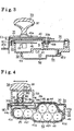
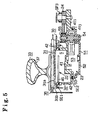
- Fig.5 illustrate a cross-section diagram cut along lines (2-2,3-3,4-4 and 5-5) as illustrated in FIG. 1.
- the door open/dose operating device 11 includes a bracket 30, a base plate 31 as a base forming a housing and an ECU case 32 forming a housing.
- An attaching hole 30a is provided at the bracket 30, which is formed relative to the frat form of the base plate 31 (a lid wall portion 31a).
- the base plate 31 is set in the attaching hole 30a and fixed by screws with the ECU case 32 to the bracket 30.
- the door open/close operating device 11 is assembled to the side door 10 with the bracket 30.
- the base plate 31 is an approximately box type comprising the lid wall portion 31a and a side wall portion 31b which extends continuously from outer peripheral surface of the lid wall portion 31a and to project in the rightward direction in Fig.2.
- the base plate 31 (the lid wall portion 31a) includes a first wall portion 31c extending vertically in Fig.1, a second wall portion 31d extending to rightward at the upper portion of the first wall portion 31c and a third wall portion 31e extending to rightward at the lower portion of the first wall portion 31c.
- the operating switch portion 21 is supported on the opposite side of the housing portion.
- the operating switch portion 21 includes an open switch 33, a lock/unlock switch 34, a child protector switch 35 and an indicator 36, and these switches (33-36) are supported by the base plate 31.
- the open switch 33 controls lock/unlock operation of the front lock 12, the rear lock 13 and the fully/half open stopper 14.
- the lock/unlock switch 34 is for allowing or not allowing the lock/unlock operation by the open switch 33 for the front lock 12, the rear lock 13 and the fully/half open stopper 14.
- the child protector switch 35 is for not allowing the lock/unlock operation of the front lock 12, the rear lock 13 and the fully/half open stopper 14 even if the open switch 33 and the lock/unlock switch 34 is operated from inside of the vehicle.
- the open switch 33 includes an operating lever 37 which is rotated by a driver.
- the operating lever 37 is provided at the upper portion of the base plate 31 (the first wall portion 31c) in Fig.1 and Fig.2.
- a rotation axis 37a projecting in the rightward direction in Fig.2 is provided at the lower portion of the operating lever 37 in Fig.2.
- a diameter of the edge of the rotation axis 37a is Increased for engaging with the base plate 31.
- an axis housing portion 31f is formed relative to the rotation axis 37a, which is projecting in leftward direction in Fig,.2.
- the axis housing portion 31f includes an axis portion which is an elastic transformable type, an approximately cylinder form and radially recessed at predetermined angles.
- the axis housing portion 31f also includes a detent pawl projecting radially in the inward direction at the edge of the axis portion.
- the rotation axis 37a is inserted into and engaged with the axis housing portion 31f and connected to the base plate 31 by a hinge, so that the operating lever 37 is supported rotatably.
- the rotation axis 37a is connected to the base plate 31 by a hinge without any through-hole.
- a predetermined clearance C1 is provided between the edges of the operating lever 37 and the base plate 31 except the engaging portion (the rotation axis 37a and the axis housing portion 31f).
- the upper portion (in Fig.2) of the operating lever 37 is provided with a projecting portion 37b facing to the base plate 31 and projecting in the rightward direction in Fig.2.
- a magnet MG1 is embedded in the projecting portion 37b for detecting an operation (movement) of the operating lever 37.
- a concave portion 31g is formed at the base plate 31 relative to the projecting portion 37b.
- a twisted spring SP1 is provided at the base plate 31 to restore the operating lever 37 to the predetermined original position after its operation.
- Each edge of the twisted spring SP1 is engaged with the operating lever 37 with biasing force on the right side and the left side in Fig.6 relative to a center line which is connecting the axis housing portion 31 and the concave portion 31g (the projecting portion 37b).
- the operating lever 37 restores to its original position by the biasing force of the twisted spring SP1 after the operating lever 37 rotates in the rightward or leftward direction in Fig.1.
- the lock/unlock switch 34 includes an operating button 38 for slide operation by the driver.
- the operating button 38 is provided below the operating lever 37 keeping a predetermined distance between the operating button 38 and the operating lever 37.
- an axis portion 38a is provided at the operating button 38 projecting in the rightward direction in Fig.2.
- a supporting portion 31h is provided at the base plate 31 with a margin in the direction of a movement of the operating button 38. The axis portion 38a is inserted into the supporting portion 31h.
- the operating button 38 As the axis portion 38a inserted through the supporting portion 31h, the operating button 38 is supported slidably in the horizontal direction in Fig.1.
- a twisted spring SP2 is provided at the base plate 31 to restore the operating button 38 to the predetermined original position after its operation.
- the twisted spring SP2 is engaged with the axis portion 38a with biasing force in the horizontal direction in Fig.4.
- the operating lever 37 restores to the original position by the biasing force of the twisted spring SP2 after the operating button 38 rotates in the rightward or leftward direction in Fig.1.
- a magnet MG2 is embedded on the right edge surface (in Fig.2) of the axis portion 38a for detecting the operation (movement) of the operating button 38.
- a concave portion 31i is formed at the base plate 31 relative to the axis portion 38a.
- the child protector switch 35 includes an operating lever 40 rotated by the driver.
- the operating lever 40 is supported rotatably within the clearance C1 which is provided between the base plate 31 and the operating lever 37.
- the operating lever 40 includes an extending portion 40a, a rotation axis 40b and a lever portion 40c.
- the extending portion 40a extends in the horizontal direction in Fig.3, and the rotation axis 40b projects in the downward direction in Fig.3, and the lever portion 40c bends from the extending portion 40a in the downward direction in Fig.3.
- the rotation axis 40b is a snap fit form including an axis portion and a detent pawl.
- the axis portion is elastic transformable approximately cylinder form and radially recessed at predetermined angles.
- the detent pawl projects in an inward radial direction at the edge of the axis portion.
- the operating lever 40 connects with the base plate 31 via the rotation axis 40b which is inserted into and engaged with a bearing hole 30b formed on the bracket 30. In this way, the operating lever 40 is supported rotatably.
- the operating lever 40 (the extending portion 40a) slides between the base plate 31 and the operating lever 37. ON or OFF condition of the child protector switch 35 is defined by the position of the operating lever 40 for its operation.
- a magnet MG3 is embedded in the operating lever 40 for detecting the movement of the operating lever 40.
- the indicator 36 is provided between the open switch 33 and the lock/unlock switch 34 and informs whether or not the unlock operation by the lock/unlock switch 34 is allowed.
- the indicator 36 is turned on or off according to the ON or OFF condition of the lock/unlock switch 34 which allows to unlock the locks.
- the ECU case 32 is an approximately box type including a base wall portion 41 and a side wall portion 42.
- the side wall portion 42 extends continuously from the base wall portion 41 and projects in the leftward direction in Fig.2 along the side wall portion 31b of the base plate 31.
- the base plate 31 and the ECU case 32 form a closed housing space S for electric components.
- a seal member SE1 is sandwiched for waterproofing between an edge surface of the side wall portion 31b and an edge surface of the side wall portion 42, in other word, the seal member SE1 is sandwiched for waterproofing between matching faces of the base plate 31 and the ECU case 32.
- the upper potion of the base wall portion 41 in Fig.2 of the ECU case 32 bulges in the leftward direction in Fig.2 with a height of a stepped wall portion 41a, and a first wall portion 41b is formed thereat.
- the center portion of the first wall portion 41b bulges in the leftward direction in Fig.2 with a height of a stepped wall portion 41c, and a second wall portion 41d is formed thereat.
- the first wall portion 41b extends continuously to the side wall portion 42 at upper portion in Flg.2.
- the lower portion (in Fig.2) of the base wall portion 41 of the ECU case 32 bulges in the rightward direction in Fig.2 with a height of a stepped wall portion 41e, and a third wall portion 41f is formed thereat.
- the third wall portion 41f bulges in the rightward direction in Fig.2 with a height of a stepped wall portion 41g, and a forth wall portion 41h is formed thereat.
- the lower portion of the base wall portion 41 bulges In the rightward direction in Fig.2 with a height of the stepped wall portion 41e and the stepped wall portion 41g, as a result, the space (housing space S) is extended.
- the stepped wall portion 41e and the stepped wall portion 41g extend continuously to the side wall portion 42 of the ECU case 32.
- a board type supporting wall portion 43 extends from the lower portion of the third wall portion 41f in Fig.2 and projecting in the leftward direction in Fig.2.
- the supporting wall portion 43 extends continuously to the side wall portion 42 in the rightward direction in Fig.4.
- the supporting wall portion 43 and a part of the side wall portion 42 comprise a flat surface.
- the flat surface comprising the supporting wall portion 43 and a part of the side wall portion 42 is provided with a capacitor case 44 as a separating member.
- the capacitor case 44 includes a supporting wall portion 44a extending toward the top end of the side wall portion 42, and a separating wall portion 44b bent from the supporting wall portion 44a and extends along the third wall portion 41f and the forth wall portion 41h.
- the capacitor case 44 bulges in the leftward direction in Fig.2 with a height of a stepped wall portion 44c, and a first separating wall portion 44e is formed thereat.
- the first separating wall portion 44e bulges in the leftward direction in Fig.2 with a height of a stepped wall portion 44d, and a second separating wall portion 44f is formed thereat.
- a stepped wall portion 44g is formed at the right portion of the separating wall portion 44b in Fig.4 extending toward the lower portion of the side wall portion 42 in the Fig.4 in a stepped pattern.
- a predetermined clearance is provided between the first separating wall portion 44e and the base plate 31, the second separating wall portion 44f is provided approximately contacting with the base plate 31.
- the housing space S formed by the base plate 31 and the ECU case 32 is divided into a first housing space S1 and a second housing space S2.
- an ECU board 46 of the ECU 22 mounting various types of electric components is housed in the first housing space S1.
- the form of the ECU board 46 approximately follows the form of the lid wall portion 31a of the base plate 31 (the first wall portion 31c and the second wall portion 31d).
- Two hole elements H1 are mounted to the ECU board 46 as detect portions. Two hole elements H1 are provided relative to the projecting portion 37b (magnet MG1) at which the operating lever 37 is at an original position. These two hole elements H1 are juxtaposed in the upright direction relative to Fig.2. Thus, when the projecting portion 37b (magnet MG1) is moved according to the operation of the operating lever 37, a magnetic flux near the hole elements H1 changes. The hole elements H1 outputs power voltage according to the magnetic flux. Thus, the EUC 22 detects the operation of the operating lever 37 based on the voltage of the hole elements H1.
- Two hole elements H2 are mounted to the ECU board 46 as detect portions provided relative to a magnet MG2 at which the operating button 38 is at an original position. These two hole elements H2 are juxtaposed in the upright direction relative to Fig.2. Thus, when the magnet MG2 is moved according to the operation of the operating lever 38, a magnetic flux near the hole elements H2 changes. The hole elements H2 outputs power voltage according to the magnetic flux. Thus, the EUC 22 detects the operation of the operating button 38 based on the voltage of the hole elements H2.
- the hole elements H3 are provided relative to the position of the operating lever 40 which is rotated according to the ON or OFF condition of the child protector switch 35.
- Two hole elements H3 detect a magnetic flux from a magnet MG3 on the ECU board 46.
- a magnetic flux near the hole elements H3 changes.
- the hole elements H3 outputs power voltage respectively according to the magnetic flux.
- the EUC 22 detects ON or OFF condition of the child protector switch 35 based on the voltage of the hole elements H2.
- An opening portion 32a is formed at the lower portion of the ECU case 32 in Fig 2, and a waterproof connector 47 as a connector is provided thereat.
- a jack 47a of the waterproof connector 47 is provided projecting outwardly from the ECU case 32.
- a gap between a wall on the external side of the waterproof connector 47 and the jack 47a is sealed for waterproofing.
- the ECU board 46 (ECU 22) is housed in the housing space S (the first housing space S1) in approximately sealed condition except an external portion of the connecting portion (the jack 47a) of the waterproof connector 47.
- the waterproof connector 47 may be formed integrally with the ECU case 32.
- the waterproof connector 47 is fixed to the ECU board 46 and electrically connected to a wire on the ECU board 46.
- the waterproof connector 47 connects to the harness on the vehicle side through the connector CN1 on the vehicle side which is inset into the waterproof connector 47.
- Various types of information of the vehicle are input to the ECU 22 (the ECU board 46) through the waterproof connector 47, and a power is supplied to the ECU 22 (the ECU board 46) from the vehicle's battery as a main power (not shown).
- a vertical direction of the door open/close operating device 11 assembled to the slide door 10 approximately corresponds to a vertical direction in Fig.1 and Fig.2.
- the waterproof connector 47 is provided at lower in the vertical direction.
- the jack 47a of the waterproof connector 47 where the connector CN1 on vehicle side is inserted in is facing in the vertical downward direction, however, the jack 47a may face in any downward direction.
- the jack 47a of the waterproof connector 47 is preferable to be facing backward of the vehicle when the jack 47a is assembled to the vehicle.
- the auxiliary power source 25 is comprised of plural capacitors 48 (7 in this embodiment) which are housed in the second housing space S2. Specifically, two capacitors 48 are housed in a line in a space between the third wall portion 41f of the base wall portion 41 and the first separating wall portion 44e of the separating wall portion 44b (capacitor case 44), and five capacitors 48 are housed alternately in two lines in a space between the forth wall portion 41h and the second separating wall portion 44f. Thus, the capacitors 48 (auxiliary power source 25) are housed in the second housing space S2, which is separated form the first housing space S1 for the ECU board 46 by the capacitor case 44.
- the capacitors 48 (auxiliary power source 25) are housed in the housing space S (the second housing space S2) in approximately sealed condition except an external portion of the connecting portion of the waterproof connector 47.
- the horizontal direction of the door open/close operating device 11 assembled to the slide door 10 approximately corresponds to a horizontal direction in Fig.1.
- the most of the capacitors 48 are provided at rear of the vertical direction.
- a capacitor board 49 which is fixed to the capacitor case 44 covers the upper portion of the second housing space S2. Terminals of each capacitor 48 is in bare condition relative to the capacitor board 49 and connected electrically to a power supply terminal of the waterproof connector 47 through a bus bar (not shown) wired to the capacitor board 49 and the wire of the ECU board 46.
- the capacitors 48 are electric double layer capacitor type. The capacitors 48 are charged by a power supplied from the vehicle's battery and supply a power secondarily to the ECU 22 and the release actuator 23 by discharging its power.
- An actuator housing 51 is fixed to the upper portion of the base wall portion 41 of the ECU case 32 on opposite side of the base plate 31, which forms a housing portion bulging in the rightward direction in Fig.2.
- an extending wall portion 41i is formed at the base wall portion 41, which extends in the rightward direction in Fig.5.
- a stepped wall portion 41j extends continuously to the extending wall portion 41i through the stepped wall portion 41a.
- the base wall portion 41 bulges in the leftward direction in Fig.2 with heights of the stepped wall portion 41a and the stepped wall portion 41j.
- the actuator housing 51 is an approximately box type including a base wall portion 52 and a side wall portion 53.
- the side wall portion 53 extends from the base wall portion 52 and projects in the leftward direction in Fig.2 along a peripheral edge portion of the base wall portion 52 approximately surrounding the stepped wall portion 41a and the stepped wall portion 41j.
- the each edge surface of the stepped wall portion 41a, the stepped wall portion 41j and the side wall portion 53 is contacting each other, and the ECU case 32 and the actuator housing 51 forms the third housing space S3 which is an approximately sealed housing space for machine parts.
- the third housing space S3 extends to the outer of the housing space S along the stepped wall portion 41j of the extending wall portion 41i.
- a seal member SE2 is sandwiched for waterproofing between edge surfaces of the stepped wall portion 41a, the stepped wall portion 41j and the side wall portion 53, in other word, the seal member SE2 is sandwiched for waterproofing between matching faces of the ECU case 32 and the actuator housing.
- the release actuator 23 is housed in the third housing space S3:
- the output axis of the release actuator 23 is rotatably supported by the ECU case 32 and the actuator housing 51 (the base wall portion 52) near the stepped wall portion 41j.
- a lower end portion of the output axis 54 extends completely through the base wall portion 41 at the outside of the side wall portion 42 (and the side wall portion 31b) of the housing space S.
- An output gear 55 is fixed by screw to a top end portion of the output axis 54 protruding to the outside of the base wall portion 41 (the third housing space S3).
- the output gear 55 is rotatably driven by a drive force of the release actuator 23 through the output axis 54.
- the release actuator 23 is housed in the third housing space S3 in approximately sealed condition except the edge portion of the output axis 54 protruding to the outside of the third housing space S3 for transmitting the drive force.
- the remote control lever 24 is rotatably supported by the extending wall portion 41i of the base wall portion 41 at the outside of the side wall portion 53 (and the stepped wall portion 41j) which forms the third housing space S3.
- the remote control lever 24 includes an input lever portion 24a and an output lever portion 24b.
- the input lever portion 24a extends toward the output gear 55 and engages with the output gear 55.
- the output lever portion 24b extends toward the outside of the base wall portion 42 (the extending wall portion 41i).
- An upper end portion of the output lever portion 24b is connected to the front lock 12, the rear lock 13 and the fully/half open stopper 14 through the connecting cables 26, 27, and 28.
- the output gear 55 is rotatably driven by a drive force of the release actuator 23, the drive force is transmitted to the remote control lever through the input lever portion 24a.
- the output lever portion 24b of the remote control lever 24 locks or unlocks the front lock 12, the rear lock 13 and the fully/half open stopper 14 transmitting the drive force to each locks and the stopper through the connecting cables 26, 27, and 28.
- a twisted spring SP3 is provided at the remote control lever 24 to restore the remote control lever 24 to a predetermined original position after its operation.
- the remote control lever 24 is restored to the predetermined original position by a biasing force generated after the remote control lever 24 is driven for lock/unlock operation of the front lock 12, the rear lock 13 and the fully/half open stopper 14.
- the capacitor case 44 and the capacitor board 49 are provided independently. This may be applied to a capacitor board 61 formed integrally with the capacitor case 44 as shown in Fig.9.
- the capacitor board 61 is formed integrally with the capacitor case 44 through a hinge portion 61 a which is relatively thin for a hinge movement of the capacitor board 61.
- the upper portion of the second housing space S2 in Fig.10 is covered/uncovered by the capacitor board 61 which makes pivotally movement via the hinge portion 61a.
- the integral structure of the capacitor case 44 and the capacitor board 61 allows the bus bar to be in stable position, and a position gap between the ECU 22 (the ECU board 46) and the bus bar, which is generated by a difference of the assembling to the housing space S, is reduced.
- guide walls 62 may be provided at the capacitor case 44 according to the position of the capacitors 48 in the second housing space S2 to settle the position of the capacitors 48 (auxiliary power source 25) as shown in Fig. 10.
- the guide walls 62 are inwardly projecting form and provided inside the second housing space S2 along the outer peripheral surface of the capacitors 48.
- guide walls 63 may be provided at the base wall portion 41 (the third wall portion 41f and the forth wall portion 41h) according to the position of the capacitors 48 in the second housing space S2 to settle the position of the capacitors 48 (auxiliary power source 25).
- the guide walls 63 are inwardly projecting form and provided inside the second housing space S2 along the outer peripheral surface of the capacitors 48.
- the guide walls 62 and the guide walls 63 settle the position of the auxiliary power source 25 (capacitors 48), and the auxiliary power source 25 is smoothly housed and assembled inside the second housing space S2.
- the guide walls 62 also prevent a joggle from the capacitors 48 in the second housing space S2.
- the capacitor board 61 When the capacitor board 61 is provided integrally with the capacitor case 44 (Fig.9), the position difference of the capacitors 48 is reduced by connecting the bus bar of the capacitor board 61 to the each terminal of the capacitors 48. The efficiency of the connecting operation is improved.
- the guide walls 63 may be formed integrally with the capacitor case 44.
- the plural capacitors 48 (auxiliary power source 25) are fixed in advance to the capacitor case 44 which is formed integrally with the guide walls, and the capacitor case 44 with the capacitors 48 is assembled to the housing space S as one component, thus, an assembling performance has been improved.
- the auxiliary power source 25 is comprised of the capacitors 48, however, the capacitor can be replaced by a chargable/dischargable battery. in this case, if the battery leaks, an adhesion of the battery electrolyte on the ECU 22 can be prevented because the ECU 22 and the capacitors 48 are separated by the capacitor case 44.
- the waterproof connector 47 connecting to the harness on the vehicle is formed integrally with the base plate 31 and the ECU case 32. In this case, the number of the components and the assembling man-hour has been reduced comparing to another device with another type of connector.
- various types of information of lock/unlock condition of the front lock 12, the rear lock 13 and the fully/half open stopper 14 may be output from the RCU22 to the vehicle through the waterproof connector 47.
- a door open/close operating device includes an operating switch, a control device, an actuator, an output member and an auxiliary power source, and these components are integrally formed.
- a purpose of the invention is providing the door open/close operating device for enhancing flexibility of assembling the door open/close operating device to the vehicle's door and reducing a man-hour for assembling.
Landscapes
- Engineering & Computer Science (AREA)
- Power Engineering (AREA)
- Lock And Its Accessories (AREA)
- Power-Operated Mechanisms For Wings (AREA)
Abstract
Description
and
Fig.7 illustrates a pattern diagram of a slide door system of a vehicle according to the embodiment of the current invention. As shown in Fig.7, a
The door open/
The extending
The
A seal member SE1 is sandwiched for waterproofing between an edge surface of the
Thus, the lower portion of the
The
Thus, the ECU board 46 (ECU 22) is housed in the housing space S (the first housing space S1) in approximately sealed condition except an external portion of the connecting portion (the
The
The capacitors 48 (auxiliary power source 25) are housed in the housing space S (the second housing space S2) in approximately sealed condition except an external portion of the connecting portion of the
The
On the other hand, the
Thus, the each edge surface of the stepped
An
Thus, when the
The second housing space S2 for the auxiliary power source 25 (capacitors 48) is formed using a certain portion of the ECU case 32 (the
However, when the force from the release actuator becomes stronger, a stroke loss is generated due to a rotatable supporting structure of the remote control lever. Transmitting mechanism portion of the remote control lever and the release actuator are need to be designed with a stroke design allowing for the difference of the distance between the pivot point of the
Thus, there is no need to use a harness for input operation of the
if the
Generally, when the vehicle sinks, the front portion of the vehicle begins to sink at first due to a heavy load, for example, a load of the engine provided at the front of the vehicle. If the jack faces in the backward direction of the vehicle, a penetration of water into the jack is delayed.
In addition, the integral structure of the
On the other hand, guide
Thus, the
A door open/close operating device includes an operating switch, a control device, an actuator, an output member and an auxiliary power source, and these components are integrally formed. A purpose of the invention is providing the door open/close operating device for enhancing flexibility of assembling the door open/close operating device to the vehicle's door and reducing a man-hour for assembling.
Claims (7)
- A door open/close operating device comprising:an operating switch;a control device which detects an operation of the operating switch;an actuator which is driven by the centre! device,an output member which is driven by the actuator and transmits a drive force from the actuator to a door open/close member, andan auxiliary power source which subsidiarily supplies a power to the control device and the actuator, wherein the operating switch, the control device, the actuator, the output member and the auxiliary power source are integrally formed.
- A door open/close operating device according to claim 1, wherein a housing portion is formed at a base which supports the operating switch.
- A door open/close operating device according to claim 2, wherein a housing space for electrical components including the control device and the auxiliary power source and a housing space for machine components such as the actuator are separately provided in the housing portion.
- A door open/close operating device according to claim 3, wherein a separating member is provided for separating the control device from the auxiliary power source in the housing space for electric components.
- A door open/close operating device according to claim 3 or claim 4, wherein the output member is integrally formed at the housing portion.
- A door open/close operating device according to any of claim 2 through claim 5, wherein a connector is formed integrally with the housing portion for connecting a harness located at a vehicle side.
- A door open/close operating device according to any of claim 2 through claim 6, wherein the operating switch includes a plurality of a noncontact switch, and each detecting portion for detecting operation of the operating switch is assembled to a board of the control device fixed inside the hosing portion facing to the operating switch across the base.
Applications Claiming Priority (2)
| Application Number | Priority Date | Filing Date | Title |
|---|---|---|---|
| JP2002254905 | 2002-08-30 | ||
| JP2002254905A JP2004092204A (en) | 2002-08-30 | 2002-08-30 | Door opening / closing operation device |
Publications (2)
| Publication Number | Publication Date |
|---|---|
| EP1394342A2 true EP1394342A2 (en) | 2004-03-03 |
| EP1394342A3 EP1394342A3 (en) | 2007-03-14 |
Family
ID=31492666
Family Applications (1)
| Application Number | Title | Priority Date | Filing Date |
|---|---|---|---|
| EP20030019782 Withdrawn EP1394342A3 (en) | 2002-08-30 | 2003-08-29 | Door Open/Close Operating Device |
Country Status (3)
| Country | Link |
|---|---|
| US (1) | US6881912B2 (en) |
| EP (1) | EP1394342A3 (en) |
| JP (1) | JP2004092204A (en) |
Cited By (3)
| Publication number | Priority date | Publication date | Assignee | Title |
|---|---|---|---|---|
| US9013056B2 (en) | 2012-02-22 | 2015-04-21 | Panasonic Intellectual Property Management Co., Ltd. | Backup power source device and automobile equipped with same |
| DE102023121579A1 (en) | 2023-08-11 | 2025-02-13 | Kiekert Aktiengesellschaft | motor vehicle lock |
| US12559997B1 (en) * | 2021-09-09 | 2026-02-24 | Kiekert Ag | Motor vehicle lock, in particular motor vehicle door lock |
Families Citing this family (11)
| Publication number | Priority date | Publication date | Assignee | Title |
|---|---|---|---|---|
| US20050216133A1 (en) * | 2004-03-25 | 2005-09-29 | Macdougall Lonny | Child lock indicator |
| DE102013103451B4 (en) * | 2012-11-13 | 2016-07-28 | Stego-Holding Gmbh | Door contact switch, in particular for control cabinets |
| DE112013006191T5 (en) | 2012-12-24 | 2015-09-10 | Magna Closures Inc. | Electronic lock of a motor vehicle locking device equipped with an improved auxiliary power source |
| CN105658889B (en) | 2013-09-25 | 2018-10-19 | 麦格纳覆盖件有限公司 | Electric vehicle latche |
| DE102014105873B4 (en) * | 2014-04-25 | 2025-06-05 | Brose Fahrzeugteile Se & Co. Kommanditgesellschaft, Bamberg | Motor vehicle lock |
| JP6969335B2 (en) * | 2017-12-06 | 2021-11-24 | 株式会社アイシン | Vehicle door handle device |
| CN110017070B (en) * | 2019-04-02 | 2023-12-05 | 广州通巴达电气科技有限公司 | Protective door and lockset |
| DE102019121300A1 (en) * | 2019-08-07 | 2021-02-11 | Daimler Ag | Motor vehicle lock, in particular motor vehicle door lock |
| JP7331317B2 (en) * | 2019-12-26 | 2023-08-23 | 三井金属アクト株式会社 | door latch device |
| DE102022114890A1 (en) | 2022-06-14 | 2023-12-14 | Kiekert Aktiengesellschaft | Motor vehicle lock with an electronic control device |
| DE102024117221A1 (en) * | 2024-06-19 | 2025-12-24 | Kiekert Aktiengesellschaft | Electric locking mechanism of a motor vehicle |
Family Cites Families (9)
| Publication number | Priority date | Publication date | Assignee | Title |
|---|---|---|---|---|
| US5535607A (en) * | 1994-06-08 | 1996-07-16 | General Motors Corporation | Door latch with integral switch |
| US5605363A (en) | 1995-02-07 | 1997-02-25 | Chrysler Corporation | Sliding door latch control assembly |
| JPH09195628A (en) * | 1996-01-16 | 1997-07-29 | Yazaki Corp | Vehicle door component mounting structure and vehicle door assembly method |
| KR200205397Y1 (en) * | 1997-08-30 | 2000-12-01 | 구자홍 | Door hinge structure of the refrigerator |
| JP3380729B2 (en) * | 1997-12-04 | 2003-02-24 | 三井金属鉱業株式会社 | Vehicle sliding door opening and closing control device |
| JP2000064685A (en) | 1998-08-26 | 2000-02-29 | Denso Corp | Door lock operating device |
| DE19961246A1 (en) * | 1999-05-18 | 2001-06-21 | Huf Huelsbeck & Fuerst Gmbh | Device for setting an opening and / or closing aid for lockable parts on vehicles, such as flaps, doors or the like. |
| JP3329319B2 (en) * | 1999-11-30 | 2002-09-30 | トヨタ車体株式会社 | Vehicle door handle |
| JP3851504B2 (en) * | 2000-11-16 | 2006-11-29 | 矢崎総業株式会社 | Automotive sliding door feeder |
-
2002
- 2002-08-30 JP JP2002254905A patent/JP2004092204A/en active Pending
-
2003
- 2003-08-29 EP EP20030019782 patent/EP1394342A3/en not_active Withdrawn
- 2003-08-29 US US10/650,695 patent/US6881912B2/en not_active Expired - Fee Related
Cited By (4)
| Publication number | Priority date | Publication date | Assignee | Title |
|---|---|---|---|---|
| US9013056B2 (en) | 2012-02-22 | 2015-04-21 | Panasonic Intellectual Property Management Co., Ltd. | Backup power source device and automobile equipped with same |
| EP2818366A4 (en) * | 2012-02-22 | 2015-06-10 | Panasonic Ip Man Co Ltd | EMERGENCY POWER SOURCE DEVICE AND MOTOR VEHICLE EQUIPPED WITH SAME |
| US12559997B1 (en) * | 2021-09-09 | 2026-02-24 | Kiekert Ag | Motor vehicle lock, in particular motor vehicle door lock |
| DE102023121579A1 (en) | 2023-08-11 | 2025-02-13 | Kiekert Aktiengesellschaft | motor vehicle lock |
Also Published As
| Publication number | Publication date |
|---|---|
| EP1394342A3 (en) | 2007-03-14 |
| US20040058563A1 (en) | 2004-03-25 |
| JP2004092204A (en) | 2004-03-25 |
| US6881912B2 (en) | 2005-04-19 |
Similar Documents
| Publication | Publication Date | Title |
|---|---|---|
| US6881912B2 (en) | Door open/close operating device | |
| KR100186787B1 (en) | Actuator for vehicle door lock | |
| KR101379391B1 (en) | Motor vehicle lock | |
| US8469412B2 (en) | Door handle device | |
| US20240209657A1 (en) | Motor vehicle lock | |
| US6371537B1 (en) | Electric lock casing for an automobile vehicle boot closure member | |
| US12037818B2 (en) | Door latch device | |
| CN107849874A (en) | Door locking device for vehicles | |
| US8604904B2 (en) | Portable device | |
| EP3992402B1 (en) | Door latch device | |
| CN114450459B (en) | Door latch device | |
| US6543918B1 (en) | Fixing structure of room lamp for vehicle | |
| CN215803900U (en) | Actuator device | |
| JP3783252B2 (en) | Door lock drive device | |
| JP4110901B2 (en) | Door opening / closing operation device | |
| JP7055953B2 (en) | Door latch device | |
| JP2004092203A (en) | Door opening / closing operation device | |
| JPH10196182A (en) | Method of manufacturing terminal device | |
| CN108868390B (en) | Vehicle locking device | |
| JP4135310B2 (en) | Door lock actuator | |
| JP4834855B2 (en) | Vehicle locking device | |
| CN114502811B (en) | Electronically actuated and locked glove box system | |
| JP2001135443A (en) | Rotating connector | |
| JP5279445B2 (en) | Latch device | |
| JP2006266027A (en) | Vehicle door lock device |
Legal Events
| Date | Code | Title | Description |
|---|---|---|---|
| PUAI | Public reference made under article 153(3) epc to a published international application that has entered the european phase |
Free format text: ORIGINAL CODE: 0009012 |
|
| AK | Designated contracting states |
Kind code of ref document: A2 Designated state(s): AT BE BG CH CY CZ DE DK EE ES FI FR GB GR HU IE IT LI LU MC NL PT RO SE SI SK TR |
|
| AX | Request for extension of the european patent |
Extension state: AL LT LV MK |
|
| PUAL | Search report despatched |
Free format text: ORIGINAL CODE: 0009013 |
|
| AK | Designated contracting states |
Kind code of ref document: A3 Designated state(s): AT BE BG CH CY CZ DE DK EE ES FI FR GB GR HU IE IT LI LU MC NL PT RO SE SI SK TR |
|
| AX | Request for extension of the european patent |
Extension state: AL LT LV MK |
|
| AKX | Designation fees paid |
Designated state(s): DE FR GB |
|
| STAA | Information on the status of an ep patent application or granted ep patent |
Free format text: STATUS: THE APPLICATION IS DEEMED TO BE WITHDRAWN |
|
| 18D | Application deemed to be withdrawn |
Effective date: 20070915 |