EP1394103B1 - Cylindrical water vapor reforming unit - Google Patents
Cylindrical water vapor reforming unit Download PDFInfo
- Publication number
- EP1394103B1 EP1394103B1 EP02730866A EP02730866A EP1394103B1 EP 1394103 B1 EP1394103 B1 EP 1394103B1 EP 02730866 A EP02730866 A EP 02730866A EP 02730866 A EP02730866 A EP 02730866A EP 1394103 B1 EP1394103 B1 EP 1394103B1
- Authority
- EP
- European Patent Office
- Prior art keywords
- catalyst layer
- layer
- cylindrical body
- reforming
- shift catalyst
- Prior art date
- Legal status (The legal status is an assumption and is not a legal conclusion. Google has not performed a legal analysis and makes no representation as to the accuracy of the status listed.)
- Expired - Lifetime
Links
Images
Classifications
-
- B—PERFORMING OPERATIONS; TRANSPORTING
- B01—PHYSICAL OR CHEMICAL PROCESSES OR APPARATUS IN GENERAL
- B01J—CHEMICAL OR PHYSICAL PROCESSES, e.g. CATALYSIS OR COLLOID CHEMISTRY; THEIR RELEVANT APPARATUS
- B01J19/00—Chemical, physical or physico-chemical processes in general; Their relevant apparatus
- B01J19/24—Stationary reactors without moving elements inside
- B01J19/248—Reactors comprising multiple separated flow channels
- B01J19/2485—Monolithic reactors
-
- C—CHEMISTRY; METALLURGY
- C01—INORGANIC CHEMISTRY
- C01B—NON-METALLIC ELEMENTS; COMPOUNDS THEREOF; METALLOIDS OR COMPOUNDS THEREOF NOT COVERED BY SUBCLASS C01C
- C01B3/00—Hydrogen; Gaseous mixtures containing hydrogen; Separation of hydrogen from mixtures containing it; Purification of hydrogen
- C01B3/02—Production of hydrogen or of gaseous mixtures containing a substantial proportion of hydrogen
- C01B3/32—Production of hydrogen or of gaseous mixtures containing a substantial proportion of hydrogen by reaction of gaseous or liquid organic compounds with gasifying agents, e.g. water, carbon dioxide, air
- C01B3/34—Production of hydrogen or of gaseous mixtures containing a substantial proportion of hydrogen by reaction of gaseous or liquid organic compounds with gasifying agents, e.g. water, carbon dioxide, air by reaction of hydrocarbons with gasifying agents
- C01B3/38—Production of hydrogen or of gaseous mixtures containing a substantial proportion of hydrogen by reaction of gaseous or liquid organic compounds with gasifying agents, e.g. water, carbon dioxide, air by reaction of hydrocarbons with gasifying agents using catalysts
-
- B—PERFORMING OPERATIONS; TRANSPORTING
- B01—PHYSICAL OR CHEMICAL PROCESSES OR APPARATUS IN GENERAL
- B01J—CHEMICAL OR PHYSICAL PROCESSES, e.g. CATALYSIS OR COLLOID CHEMISTRY; THEIR RELEVANT APPARATUS
- B01J8/00—Chemical or physical processes in general, conducted in the presence of fluids and solid particles; Apparatus for such processes
- B01J8/02—Chemical or physical processes in general, conducted in the presence of fluids and solid particles; Apparatus for such processes with stationary particles, e.g. in fixed beds
- B01J8/04—Chemical or physical processes in general, conducted in the presence of fluids and solid particles; Apparatus for such processes with stationary particles, e.g. in fixed beds the fluid passing successively through two or more beds
- B01J8/0446—Chemical or physical processes in general, conducted in the presence of fluids and solid particles; Apparatus for such processes with stationary particles, e.g. in fixed beds the fluid passing successively through two or more beds the flow within the beds being predominantly vertical
- B01J8/0461—Chemical or physical processes in general, conducted in the presence of fluids and solid particles; Apparatus for such processes with stationary particles, e.g. in fixed beds the fluid passing successively through two or more beds the flow within the beds being predominantly vertical in two or more cylindrical annular shaped beds
- B01J8/0465—Chemical or physical processes in general, conducted in the presence of fluids and solid particles; Apparatus for such processes with stationary particles, e.g. in fixed beds the fluid passing successively through two or more beds the flow within the beds being predominantly vertical in two or more cylindrical annular shaped beds the beds being concentric
-
- B—PERFORMING OPERATIONS; TRANSPORTING
- B01—PHYSICAL OR CHEMICAL PROCESSES OR APPARATUS IN GENERAL
- B01J—CHEMICAL OR PHYSICAL PROCESSES, e.g. CATALYSIS OR COLLOID CHEMISTRY; THEIR RELEVANT APPARATUS
- B01J8/00—Chemical or physical processes in general, conducted in the presence of fluids and solid particles; Apparatus for such processes
- B01J8/02—Chemical or physical processes in general, conducted in the presence of fluids and solid particles; Apparatus for such processes with stationary particles, e.g. in fixed beds
- B01J8/04—Chemical or physical processes in general, conducted in the presence of fluids and solid particles; Apparatus for such processes with stationary particles, e.g. in fixed beds the fluid passing successively through two or more beds
- B01J8/0492—Feeding reactive fluids
-
- B—PERFORMING OPERATIONS; TRANSPORTING
- B01—PHYSICAL OR CHEMICAL PROCESSES OR APPARATUS IN GENERAL
- B01J—CHEMICAL OR PHYSICAL PROCESSES, e.g. CATALYSIS OR COLLOID CHEMISTRY; THEIR RELEVANT APPARATUS
- B01J8/00—Chemical or physical processes in general, conducted in the presence of fluids and solid particles; Apparatus for such processes
- B01J8/02—Chemical or physical processes in general, conducted in the presence of fluids and solid particles; Apparatus for such processes with stationary particles, e.g. in fixed beds
- B01J8/04—Chemical or physical processes in general, conducted in the presence of fluids and solid particles; Apparatus for such processes with stationary particles, e.g. in fixed beds the fluid passing successively through two or more beds
- B01J8/0496—Heating or cooling the reactor
-
- C—CHEMISTRY; METALLURGY
- C01—INORGANIC CHEMISTRY
- C01B—NON-METALLIC ELEMENTS; COMPOUNDS THEREOF; METALLOIDS OR COMPOUNDS THEREOF NOT COVERED BY SUBCLASS C01C
- C01B3/00—Hydrogen; Gaseous mixtures containing hydrogen; Separation of hydrogen from mixtures containing it; Purification of hydrogen
- C01B3/02—Production of hydrogen or of gaseous mixtures containing a substantial proportion of hydrogen
- C01B3/32—Production of hydrogen or of gaseous mixtures containing a substantial proportion of hydrogen by reaction of gaseous or liquid organic compounds with gasifying agents, e.g. water, carbon dioxide, air
- C01B3/34—Production of hydrogen or of gaseous mixtures containing a substantial proportion of hydrogen by reaction of gaseous or liquid organic compounds with gasifying agents, e.g. water, carbon dioxide, air by reaction of hydrocarbons with gasifying agents
- C01B3/38—Production of hydrogen or of gaseous mixtures containing a substantial proportion of hydrogen by reaction of gaseous or liquid organic compounds with gasifying agents, e.g. water, carbon dioxide, air by reaction of hydrocarbons with gasifying agents using catalysts
- C01B3/384—Production of hydrogen or of gaseous mixtures containing a substantial proportion of hydrogen by reaction of gaseous or liquid organic compounds with gasifying agents, e.g. water, carbon dioxide, air by reaction of hydrocarbons with gasifying agents using catalysts the catalyst being continuously externally heated
-
- C—CHEMISTRY; METALLURGY
- C01—INORGANIC CHEMISTRY
- C01B—NON-METALLIC ELEMENTS; COMPOUNDS THEREOF; METALLOIDS OR COMPOUNDS THEREOF NOT COVERED BY SUBCLASS C01C
- C01B3/00—Hydrogen; Gaseous mixtures containing hydrogen; Separation of hydrogen from mixtures containing it; Purification of hydrogen
- C01B3/02—Production of hydrogen or of gaseous mixtures containing a substantial proportion of hydrogen
- C01B3/32—Production of hydrogen or of gaseous mixtures containing a substantial proportion of hydrogen by reaction of gaseous or liquid organic compounds with gasifying agents, e.g. water, carbon dioxide, air
- C01B3/34—Production of hydrogen or of gaseous mixtures containing a substantial proportion of hydrogen by reaction of gaseous or liquid organic compounds with gasifying agents, e.g. water, carbon dioxide, air by reaction of hydrocarbons with gasifying agents
- C01B3/48—Production of hydrogen or of gaseous mixtures containing a substantial proportion of hydrogen by reaction of gaseous or liquid organic compounds with gasifying agents, e.g. water, carbon dioxide, air by reaction of hydrocarbons with gasifying agents followed by reaction of water vapour with carbon monoxide
-
- B—PERFORMING OPERATIONS; TRANSPORTING
- B01—PHYSICAL OR CHEMICAL PROCESSES OR APPARATUS IN GENERAL
- B01J—CHEMICAL OR PHYSICAL PROCESSES, e.g. CATALYSIS OR COLLOID CHEMISTRY; THEIR RELEVANT APPARATUS
- B01J2208/00—Processes carried out in the presence of solid particles; Reactors therefor
- B01J2208/00008—Controlling the process
- B01J2208/00017—Controlling the temperature
- B01J2208/00106—Controlling the temperature by indirect heat exchange
- B01J2208/00168—Controlling the temperature by indirect heat exchange with heat exchange elements outside the bed of solid particles
- B01J2208/00203—Coils
-
- B—PERFORMING OPERATIONS; TRANSPORTING
- B01—PHYSICAL OR CHEMICAL PROCESSES OR APPARATUS IN GENERAL
- B01J—CHEMICAL OR PHYSICAL PROCESSES, e.g. CATALYSIS OR COLLOID CHEMISTRY; THEIR RELEVANT APPARATUS
- B01J2208/00—Processes carried out in the presence of solid particles; Reactors therefor
- B01J2208/00008—Controlling the process
- B01J2208/00017—Controlling the temperature
- B01J2208/00477—Controlling the temperature by thermal insulation means
- B01J2208/00495—Controlling the temperature by thermal insulation means using insulating materials or refractories
-
- B—PERFORMING OPERATIONS; TRANSPORTING
- B01—PHYSICAL OR CHEMICAL PROCESSES OR APPARATUS IN GENERAL
- B01J—CHEMICAL OR PHYSICAL PROCESSES, e.g. CATALYSIS OR COLLOID CHEMISTRY; THEIR RELEVANT APPARATUS
- B01J2208/00—Processes carried out in the presence of solid particles; Reactors therefor
- B01J2208/00008—Controlling the process
- B01J2208/00017—Controlling the temperature
- B01J2208/00504—Controlling the temperature by means of a burner
-
- B—PERFORMING OPERATIONS; TRANSPORTING
- B01—PHYSICAL OR CHEMICAL PROCESSES OR APPARATUS IN GENERAL
- B01J—CHEMICAL OR PHYSICAL PROCESSES, e.g. CATALYSIS OR COLLOID CHEMISTRY; THEIR RELEVANT APPARATUS
- B01J2208/00—Processes carried out in the presence of solid particles; Reactors therefor
- B01J2208/00008—Controlling the process
- B01J2208/00017—Controlling the temperature
- B01J2208/0053—Controlling multiple zones along the direction of flow, e.g. pre-heating and after-cooling
-
- C—CHEMISTRY; METALLURGY
- C01—INORGANIC CHEMISTRY
- C01B—NON-METALLIC ELEMENTS; COMPOUNDS THEREOF; METALLOIDS OR COMPOUNDS THEREOF NOT COVERED BY SUBCLASS C01C
- C01B2203/00—Integrated processes for the production of hydrogen or synthesis gas
- C01B2203/02—Processes for making hydrogen or synthesis gas
- C01B2203/0205—Processes for making hydrogen or synthesis gas containing a reforming step
- C01B2203/0227—Processes for making hydrogen or synthesis gas containing a reforming step containing a catalytic reforming step
- C01B2203/0233—Processes for making hydrogen or synthesis gas containing a reforming step containing a catalytic reforming step the reforming step being a steam reforming step
-
- C—CHEMISTRY; METALLURGY
- C01—INORGANIC CHEMISTRY
- C01B—NON-METALLIC ELEMENTS; COMPOUNDS THEREOF; METALLOIDS OR COMPOUNDS THEREOF NOT COVERED BY SUBCLASS C01C
- C01B2203/00—Integrated processes for the production of hydrogen or synthesis gas
- C01B2203/02—Processes for making hydrogen or synthesis gas
- C01B2203/0283—Processes for making hydrogen or synthesis gas containing a CO-shift step, i.e. a water gas shift step
-
- C—CHEMISTRY; METALLURGY
- C01—INORGANIC CHEMISTRY
- C01B—NON-METALLIC ELEMENTS; COMPOUNDS THEREOF; METALLOIDS OR COMPOUNDS THEREOF NOT COVERED BY SUBCLASS C01C
- C01B2203/00—Integrated processes for the production of hydrogen or synthesis gas
- C01B2203/04—Integrated processes for the production of hydrogen or synthesis gas containing a purification step for the hydrogen or the synthesis gas
- C01B2203/0435—Catalytic purification
- C01B2203/044—Selective oxidation of carbon monoxide
-
- C—CHEMISTRY; METALLURGY
- C01—INORGANIC CHEMISTRY
- C01B—NON-METALLIC ELEMENTS; COMPOUNDS THEREOF; METALLOIDS OR COMPOUNDS THEREOF NOT COVERED BY SUBCLASS C01C
- C01B2203/00—Integrated processes for the production of hydrogen or synthesis gas
- C01B2203/04—Integrated processes for the production of hydrogen or synthesis gas containing a purification step for the hydrogen or the synthesis gas
- C01B2203/0465—Composition of the impurity
- C01B2203/047—Composition of the impurity the impurity being carbon monoxide
-
- C—CHEMISTRY; METALLURGY
- C01—INORGANIC CHEMISTRY
- C01B—NON-METALLIC ELEMENTS; COMPOUNDS THEREOF; METALLOIDS OR COMPOUNDS THEREOF NOT COVERED BY SUBCLASS C01C
- C01B2203/00—Integrated processes for the production of hydrogen or synthesis gas
- C01B2203/06—Integration with other chemical processes
- C01B2203/066—Integration with other chemical processes with fuel cells
-
- C—CHEMISTRY; METALLURGY
- C01—INORGANIC CHEMISTRY
- C01B—NON-METALLIC ELEMENTS; COMPOUNDS THEREOF; METALLOIDS OR COMPOUNDS THEREOF NOT COVERED BY SUBCLASS C01C
- C01B2203/00—Integrated processes for the production of hydrogen or synthesis gas
- C01B2203/08—Methods of heating or cooling
- C01B2203/0805—Methods of heating the process for making hydrogen or synthesis gas
- C01B2203/0811—Methods of heating the process for making hydrogen or synthesis gas by combustion of fuel
- C01B2203/0816—Heating by flames
-
- C—CHEMISTRY; METALLURGY
- C01—INORGANIC CHEMISTRY
- C01B—NON-METALLIC ELEMENTS; COMPOUNDS THEREOF; METALLOIDS OR COMPOUNDS THEREOF NOT COVERED BY SUBCLASS C01C
- C01B2203/00—Integrated processes for the production of hydrogen or synthesis gas
- C01B2203/08—Methods of heating or cooling
- C01B2203/0805—Methods of heating the process for making hydrogen or synthesis gas
- C01B2203/0811—Methods of heating the process for making hydrogen or synthesis gas by combustion of fuel
- C01B2203/0822—Methods of heating the process for making hydrogen or synthesis gas by combustion of fuel the fuel containing hydrogen
-
- C—CHEMISTRY; METALLURGY
- C01—INORGANIC CHEMISTRY
- C01B—NON-METALLIC ELEMENTS; COMPOUNDS THEREOF; METALLOIDS OR COMPOUNDS THEREOF NOT COVERED BY SUBCLASS C01C
- C01B2203/00—Integrated processes for the production of hydrogen or synthesis gas
- C01B2203/08—Methods of heating or cooling
- C01B2203/0805—Methods of heating the process for making hydrogen or synthesis gas
- C01B2203/0811—Methods of heating the process for making hydrogen or synthesis gas by combustion of fuel
- C01B2203/0827—Methods of heating the process for making hydrogen or synthesis gas by combustion of fuel at least part of the fuel being a recycle stream
-
- C—CHEMISTRY; METALLURGY
- C01—INORGANIC CHEMISTRY
- C01B—NON-METALLIC ELEMENTS; COMPOUNDS THEREOF; METALLOIDS OR COMPOUNDS THEREOF NOT COVERED BY SUBCLASS C01C
- C01B2203/00—Integrated processes for the production of hydrogen or synthesis gas
- C01B2203/08—Methods of heating or cooling
- C01B2203/0805—Methods of heating the process for making hydrogen or synthesis gas
- C01B2203/0838—Methods of heating the process for making hydrogen or synthesis gas by heat exchange with exothermic reactions, other than by combustion of fuel
- C01B2203/0844—Methods of heating the process for making hydrogen or synthesis gas by heat exchange with exothermic reactions, other than by combustion of fuel the non-combustive exothermic reaction being another reforming reaction as defined in groups C01B2203/02 - C01B2203/0294
-
- C—CHEMISTRY; METALLURGY
- C01—INORGANIC CHEMISTRY
- C01B—NON-METALLIC ELEMENTS; COMPOUNDS THEREOF; METALLOIDS OR COMPOUNDS THEREOF NOT COVERED BY SUBCLASS C01C
- C01B2203/00—Integrated processes for the production of hydrogen or synthesis gas
- C01B2203/08—Methods of heating or cooling
- C01B2203/0805—Methods of heating the process for making hydrogen or synthesis gas
- C01B2203/0866—Methods of heating the process for making hydrogen or synthesis gas by combination of different heating methods
-
- C—CHEMISTRY; METALLURGY
- C01—INORGANIC CHEMISTRY
- C01B—NON-METALLIC ELEMENTS; COMPOUNDS THEREOF; METALLOIDS OR COMPOUNDS THEREOF NOT COVERED BY SUBCLASS C01C
- C01B2203/00—Integrated processes for the production of hydrogen or synthesis gas
- C01B2203/08—Methods of heating or cooling
- C01B2203/0872—Methods of cooling
- C01B2203/0888—Methods of cooling by evaporation of a fluid
- C01B2203/0894—Generation of steam
-
- C—CHEMISTRY; METALLURGY
- C01—INORGANIC CHEMISTRY
- C01B—NON-METALLIC ELEMENTS; COMPOUNDS THEREOF; METALLOIDS OR COMPOUNDS THEREOF NOT COVERED BY SUBCLASS C01C
- C01B2203/00—Integrated processes for the production of hydrogen or synthesis gas
- C01B2203/10—Catalysts for performing the hydrogen forming reactions
- C01B2203/1005—Arrangement or shape of catalyst
- C01B2203/1011—Packed bed of catalytic structures, e.g. particles, packing elements
-
- C—CHEMISTRY; METALLURGY
- C01—INORGANIC CHEMISTRY
- C01B—NON-METALLIC ELEMENTS; COMPOUNDS THEREOF; METALLOIDS OR COMPOUNDS THEREOF NOT COVERED BY SUBCLASS C01C
- C01B2203/00—Integrated processes for the production of hydrogen or synthesis gas
- C01B2203/10—Catalysts for performing the hydrogen forming reactions
- C01B2203/1005—Arrangement or shape of catalyst
- C01B2203/1023—Catalysts in the form of a monolith or honeycomb
-
- C—CHEMISTRY; METALLURGY
- C01—INORGANIC CHEMISTRY
- C01B—NON-METALLIC ELEMENTS; COMPOUNDS THEREOF; METALLOIDS OR COMPOUNDS THEREOF NOT COVERED BY SUBCLASS C01C
- C01B2203/00—Integrated processes for the production of hydrogen or synthesis gas
- C01B2203/80—Aspect of integrated processes for the production of hydrogen or synthesis gas not covered by groups C01B2203/02 - C01B2203/1695
- C01B2203/82—Several process steps of C01B2203/02 - C01B2203/08 integrated into a single apparatus
-
- Y—GENERAL TAGGING OF NEW TECHNOLOGICAL DEVELOPMENTS; GENERAL TAGGING OF CROSS-SECTIONAL TECHNOLOGIES SPANNING OVER SEVERAL SECTIONS OF THE IPC; TECHNICAL SUBJECTS COVERED BY FORMER USPC CROSS-REFERENCE ART COLLECTIONS [XRACs] AND DIGESTS
- Y02—TECHNOLOGIES OR APPLICATIONS FOR MITIGATION OR ADAPTATION AGAINST CLIMATE CHANGE
- Y02P—CLIMATE CHANGE MITIGATION TECHNOLOGIES IN THE PRODUCTION OR PROCESSING OF GOODS
- Y02P20/00—Technologies relating to chemical industry
- Y02P20/10—Process efficiency
- Y02P20/129—Energy recovery, e.g. by cogeneration, H2recovery or pressure recovery turbines
Definitions
- This invention relates to a cylindrical steam reforming unit for preparing a reformed gas mainly composed of hydrogen by subjecting, to steam reforming, hydrocarbon fuels such as city gas, LPG and the like and more particularly, to a cylindrical steam reforming unit used in Polymer Electrolyte Fuel Cell (PEFC).
- PEFC Polymer Electrolyte Fuel Cell
- a reforming unit described, for example, in WO 00/63114 is known.
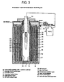
- This reforming unit is one that is to prepare a reformed gas of high hydrogen concentration mainly used in a polymer electrolyte fuel cell and as shown in Fig.
- a burner (70) is disposed at the center of a plurality of cylindrical tubular bodies (61 ⁇ 69) wherein a combustion gas passage (71), a preheating layer (72), a reforming catalyst layer (73), a heat recovery layer (74), a CO shift catalyst layer (75), a CO removal catalyst layer (78) and the like are formed in spaces of the tubular bodies around the burner (70), respectively.
- a reforming unit has the following problems (1) ⁇ (3) and has to be further modified.
- EP-A-0 922 666 relates to a cylindrical steam reforming unit comprising a first cylindrical body, a second cylindrical body and a third cylindrical body disposed in concentrically spaced relation and successively increasing in diameters, wherein said first cylindrical body has a bottom plate and said third cylindrical body has a bottom plate.
- a reforming catalyst layer is formed in a gap partitioned radially by said first cylindrical body and said second cylindrical body for reforming a starting gas, and a preheating layer is disposed upstream of said reforming catalyst layer for preheating the starting gas.
- a CO removal catalyst layer is disposed downstream of a direction of flow of a reformed gas from said CO shift catalyst layer.
- a burner is provided to generate a combustion exhaust gas.
- Patent Abstracts of Japan vol. 2000, no. 08, October 6, 2000 & JP 2000 128505 A (Tokyo Gas Co Ltd; Mitsubishi Heavy Ind Ltd), May 9, 2009
- Patent Abstracts of Japan vol. 018, no. 5888(C-1271), November 10, 1994 & JP 06 219704 A (Toshiba Corp.), August 9, 1994
- Patent Abstracts of Japan vol. 014, no. 0124 (C-677), January 18, 1990 & JP 01 264903 A Korean Steel Ltd
- the invention has been accomplished in view of such problems as set forth above with respect to the steam reforming unit and has for its object the provision of a cylindrical steam reforming unit which is small in size and light in weight, has good startup characteristics, can be operated at a high thermal efficiency and is able to stably produce hydrogen.
- the invention is defined in claim 1.
- the cylindrical reforming unit of the invention is directed to a cylindrical steam reforming unit, which comprises a plurality of cylindrical bodies consisting of a first cylindrical body, a second cylindrical body and a third cylindrical body of successively increasing diameters disposed in concentric spaced relation, a radiation cylinder disposed within and spaced at a central axis thereof concentrically with the first cylindrical body, a burner disposed at the radial central portion of the radiation cylinder, a reforming catalyst layer with a reforming catalyst filled in a gap radially established between the first and second cylindrical bodies, a CO shift catalyst layer and a CO removal catalyst layer provided in a gap established between the second and third cylindrical bodies provided around the reforming catalyst layer, and the CO shift catalyst layer being formed in a gap with the direction of flow reversed with the reforming catalyst layer at one axial end thereof and through a heat recovery layer of predetermined length.
- a heat transfer tube is disposed around the third cylindrical body and water is passed through the heat transfer tube not only to generate steam for reforming, but also to cool the CO shift catalyst layer and the CO removal catalyst layer.
- the CO shift catalyst layer is disposed at the periphery of the reform ing catalyst layer and formed within a space with the direction of flow reversed at one axial end of the reforming catalyst layer. More particularly, the CO shift catalyst layer is formed in a gap established between the second cylindrical and third cylindrical bodies and is so arranged that the gas passage from the reforming catalyst layer is reversed at the lower end of the second cylindrical body and is communicated with the CO shift catalyst layer. In this way, because heat that is greater than the heat of evaporation required in the heat transfer tube can be supplied (i.e.
- the CO shift catalyst can be successively raised from the upstream side of the CO shift catalyst layer.
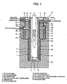
- Fig. 1 is a longitudinal sectional view showing an embodiment of a cylindrical reform ing unit according to the invention.
- This reforming unit is constituted of a plurality of cylindrical bodies of different diameters disposed about the same central axis in multiple, spaced relation. More particularly, a first cylindrical body (1), a second cylindrical body (2) and a third cylindrical body (3) of successively increasing diameters are concentrically disposed in spaced relation with one another.
- a cylindrical heat transfer partition wall (4) i.e. a radiation cylinder (4), is disposed in the first cylindrical body (1) as having the same central axis and being smaller in diameter than the first cylindrical body (1).
- a burner (5) is disposed within the radiation cylinder (4). The burner (5) is attached to the inside of the radiation cylinder (4) through an upper cover- burner mount (6).
- the radiation cylinder (4) is disposed in spaced relation between the lower end thereof and a bottom plate (7) of the first cylindrical body (1). This space and a gap associated therewith and established between the radiation cylinder (4) and the first cylindrical body (1) form an exhaust gas passage (8) of a combustion exhaust gas from the burner (5).
- the exhaust gas passage (8) is communicated, at the upper portion thereof, with an outlet (10) of the combustion exhaust gas through a space between an upper cover (9) of the exhaust gas passage (8) and an upper cover (13) of a preheating layer (14), from which the combustion exhaust gas is discharged.
- the preheating layer (14) and a reforming catalyst layer (15) are disposed in the space between the fist cylindrical body (1) and the second cylindrical body (2).
- the starting gas is fed from a feed port (11) and is introduced into the reforming catalyst layer (15) via the preheating layer (14) and reformed therein.
- the first cylindrical body (2) is disposed in spaced relation between the lower end thereof and a bottom plate (22) of the third cylindrical body (3).
- Air is supplied from an air feed port (18) to the air mixing chamber, and the supplied air is mixed, in the air mixing chamber, with a reforming gas passed through the CO shift catalyst layer (16).
- the reforming gas passed through the CO removal catalyst layer (19) is withdrawn from an outlet (21) for reform ing gas.
- the CO removal catalyst layer may also be called PROX layer.
- the reform ing unit is provided, at the side surface thereof, with a feed port (11) for starting gas, air feed port (18) for CO removal and outlet (21) for reformed gas as set out hereinabove.
- the preheating layer (14) is packed with a filler of a given shape such as alumina balls, a mesh-shaped metal or the like. This permits the starting gas and steam (or steam and water) passing through the preheating layer (14) to be efficiently heated. The flow rate is accelerated by the action of the filler being packed, so that the pulsation of the two-phase stream of the starting gas and steam and water can be prevented.
- the reforming catalyst layer (15) is packed with a catalyst for reforming a starting gas with steam, and is communicated at the lower portion thereof with the lower end of the CO shift catalyst layer (16) through a space formed between a bottom plate (7) of the first cylindrical body (1) and the bottom plate (22) of the third cylindrical body (3). More particularly, the space forms a passage of a reformed gas produced in the reforming catalyst layer (15).
- a catalyst for reforming catalyst
- any type of catalyst that is able to reform a starting gas with steam is usable without any limitation.
- a Ni or Ru-based metal catalyst is used. These metal catalysts are so arranged that a metal catalyst such as NI or Ru is supported on a carrier such as alumina.
- methane gas used for example, as a starting gas, the gas is reformed according to the following reaction (I) in the reforming catalyst layer (15) CH 4 + H 2 O ⁇ CO + 3H 2 (I)
- the reforming reaction in the reforming catalyst layer is an endothermic reaction and proceeds by absorption of the heat of combustion of the burner (5). More particularly, when the combustion exhaust gas from the burner (5) passes through the exhaust gas passage (8) established between the heat transfer partition wall (4) and the reforming catalyst layer (15), the heat of the combustion exhaust gas is absorbed with the reforming catalyst layer (15), whereupon the reforming reaction is carried out.
- a monolithic reforming catalyst may be used, aside from a granular reforming catalyst, as the reforming catalyst in the reforming catalyst layer (15).
- the reforming catalyst is used at a temperature as high as about 700°C. If the reforming unit is used, for example, in a domestic co-generation system (co-generator system), it is necessary to carry out starting up and stopping operations frequently. Where a granular reforming catalyst is used, a problem arises in that the catalyst packed in the reforming catalyst layer is crushed and broken into pieces by repetition of temperature rise and fall, so that the catalytic activity lowers. To avoid this, a monolithic reforming catalyst is used as a reforming catalyst so that the problem, which will be encountered when a granular reforming catalyst is used, can be solved.
- the monolithic catalyst can withstand vibrations or high-temperature environments and are in frequent use, mainly, as an exhaust gas purification catalyst for motor vehicle
- the monolithic reforming catalyst is disposed singly or plurally in the reforming catalyst layer (15) for use as a reform ing catalyst as a whole. This is true of not only the first cylindrical reforming unit, but also the second cylindrical reforming unit described hereinafter.
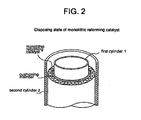
- Fig. 2 is a view showing an embodiment where a monolithic catalyst is disposed.
- This monolithic catalyst is placed in the reforming catalyst layer (15) established between the first cylindrical body (1) and the second cylindrical body (2).
- the catalyst does not settle down when suffering thermal displacement such as by expansion and contraction of the first cylindrical body (1), so that the settlement and division into pieces of the granules of catalyst as will be caused with the case of a granular reforming catalyst can be suppressed.
- Mention is made of cordierite as an example of a ceramic material constituting the carrier of the monolithic reforming catalyst.
- the metal constituting the carrier include stainless steels.
- a cushioning material capable of absorbing the thermal displacement is placed between the monolithic reforming catalyst and the first cylindrical body (1), the thermal displacement on the monolithic catalyst can be further suppressed.
- a wire mesh may be used as the cushioning material.
- the use of a metal having good heat transferability as a mesh material is convenient as not lowering heat transferability.
- a catalyst mainly composed of platinum is used for the CO shift catalyst in the CO shift catalyst layer (16).
- the catalyst mainly composed of platinum is constituted by supporting platinum on a carrier such as alumina or the like.
- the catalyst mainly composed of platinum is unlikely to undergo degradation such as by oxidation and can be continuously employed within a high temperature range of 350°C or over, especially within a high temperature range of 400°C or over, thereby permitting the reaction to proceed at a higher rate.
- mere application of a platinum-based catalyst to the CO shift reaction may cause a side reaction called methanation reaction (III) indicated below in a high temperature range, thereby im peding the intended CO shift reaction CO + 3H 2 ⁇ CH 4 +H 2 O (III)
- a catalyst which is composed of a major component of platinum along with a metal oxide such as CeO 2 or the like used as an minor component, is used. This permits the methanation reaction to be suppressed from occurring in a high temperature range.
- a CO shift catalyst called "AD catalyst” available from Matsushita Electric Industrial Co., Ltd., is known.
- Fe/Cr-based high temperature CO shift catalysts may also be used as the CO shift catalyst.
- high temperature CO shift catalysts where base metals such as Al, Cu, Fe, Cr, Mo and the like are supported on a carrier such as of Zr may also be used. It will be noted that the high temperature CO shift catalyst may be used in combination with a low temperature CO shift catalyst.
- a CO removal catalyst any type of catalyst capable of selectively oxidizing CO in a reforming gas can be used without limitation and for example, a Ru-based metal catalyst is used.
- the metal catalyst is constituted, for example, by supporting a metal catalyst such as Ru on a carrier such as alumina.
- the reaction in the CO removal catalyst layer (19) proceeds according to the following formula (IV). 2CO + O 2 ⁇ 2CO 2 (IV)
- the reforming gas from which CO has been removed in the CO removal catalyst layer (19) is withdrawn from a withdrawal port (21) of reformed gas.
- the withdrawal port (21) of reforming gas is connected to a fuel gas feed tube which is in turn connected, for example, to a polymer electrolyte fuel cell (PEFC, not shown).
- a polymer electrolyte fuel cell PEFC, not shown.
- the reformed gas containing a predetermined concentration of hydrogen is supplied to a fuel electrode side of a polymer electrolyte fuel cell and is used as a fuel for power generation.
- the offgas from the fuel electrode of the polymer electrolyte fuel cell may be used as a fuel gas for combustion with the burner (5).
- heat insulating material (34) heat insulating materials having a good heat insulating effect such as, for example, microtherm, calcium silicate, alumina fibers and the like are employed.
- Water for reforming is supplied and the burner (5) is ignited to heat the inside of the reform ing unit.
- the burner (5) is able to heat the heat transfer partition wall (4) by application of heat of radiation from the flame, and the combustion exhaust gas passes through the passage (8) between the heat transfer partition wall (4) and the first cylindrical body (1). In this way, the reforming catalyst layer (15) and the preheating layer (14) are, respectively, heated.
- the combustion exhaust gas is discharged from an outlet (10).
- the starting gas effectively absorbs the heat of combustion at the burner (5) with the aid of the heat transfer promoting effect of a filler packed in the preheating layer (14) and is thus heated to a given temperature necessary for the reform ing reaction, followed by passing into the reform ing catalyst layer (15) where the gas is reformed.
- the reforming reaction in the reforming catalyst layer (15) comes close to equilibrium, the resulting reformed gas runs out from the lower portion of the reforming catalyst layer (15) and is turned up at the lower end thereof.
- the CO shift reaction in the CO shift catalyst layer is an exothermic reaction, and the reaction commences from about 200°C, like a Cu-Zn-based catalyst.
- the reformed gas is withdrawn from the withdrawal port (21) through a multitude of holes (33) provided along the periphery of the partition board (32).
- the reforming unit is provided with the CO shift catalyst layer (16) and the CO removal catalyst layer (19) around the reforming catalyst layer (15) without interposing a heating insulating layer, a cooling mechanism and the like.
- the heat of combustion of the burner (5) is able to raise the temperatures of the CO shift catalyst layer (16) and the CO removal catalyst layer (19) within a relatively short time and contributes to generation of required steam.
- the combustion exhaust gas from the burner (5) runs and passes between the heat transfer partition wall (4) and the first cylindrical body (1), so that heat contained in the combustion exhaust gas can be effectively absorbed, resulting in fuel saving in the course of startup operation.
- the unit can be raised to a temperature necessary for startup operation within a short time, a fuel can be saved, and a very quick startup operation can be perform ed.
- CO in the reformed gas is selectively oxidized.
- the reformed gas obtained after removal of CO through the oxidation reaction of CO in the CO removal catalyst layer (19) becomes a gas which contains, for example, 75% of hydrogen, 2% of methane, 20% of carbon dioxide, 3% of nitrogen and not larger than 10 ppm of carbon monoxide, and is withdrawn from the withdrawal port (21).
- the reformed gas has a carbon monoxide concentration of 10 ppm or below and can be used, for example, as a fuel for polymer electrolyte fuel cell.
- a heat transfer tube (26) serving also as a feed water preheater is wound around the upper cover- burner mount (6) for holding the burner (5) as coming substantially to full circle.
- the heat transfer tube (26) substantially makes the circuit of the periphery of the upper cover-burner mount (6) and arrives via a connection tube (25) at a lower end of a heat-insulating member (44) described hereinafter, and is connected to a starting gas feed tube (11) while spirally ascending the periphery thereof.
- the reforming unit is so arranged with respect to the preheating layer (14) that the preheating layer (14) is provided at an upper portion between the first cylindrical body and the second cylindrical body and the reform ing catalyst layer (15) is provided at a lower portion contiguous to the upper portion.
- a round bar (41) is spirally-disposed inside the preheating layer (14), so that one continuous spiral passage is established within the preheating layer (14).
- the heat recovery layer (42) has a plurality of round bars (43) spirally disposed therein.
- the inner space of the heat recovery layer (42) is spirally divided off by means of the plural round bars (43), thereby establishing a plurality of spiral passages therein.
- the length of the spiral passage in the heat recover layer (42) is one which is sufficient to render the temperature of the reformed gas flowing into the CO shift catalyst layer (16) not higher than the heat-resistant temperature of a CO shift catalyst.
- the catalyst packed in the CO shift catalyst layer (16) may be a conventional one (i.e. a Cu/Zn-based low temperature CO shift catalyst or the like), the use of a catalyst which can be used continuously at least at 350°C or over (i.e. a platinum-based or Fe/Cr-based high temperature CO shift catalyst or the like) enables one to shorten the length of the heat recovery layer (42) and the CO shift catalyst layer (16) and make these layers small in size, thereby realizing a small-sized, light-weight reforming unit as a whole.
- a catalyst which can be used continuously at least at 350°C or over i.e. a platinum-based or Fe/Cr-based high temperature CO shift catalyst or the like
- the CO shift catalyst layer (16) is provided between the second cylindrical body (2) and the third cylindrical body (3) and is disposed with the heat insulating member (44) therearound.
- the heat insulating member (44) is wound therearound with the heat transfer tube (26) via a circular cylindrical body constituted of a thin sheet (45). More particularly, the heat insulating member (44) is disposed between the third cylindrical body (3) and the circular cylindrical body made of the thin sheet (45) and serves as a cooling mechanism for indirectly cooling the CO shift catalyst layer (16) by means of the heat transfer tube (26).
- those having good processability, such as ceramic fibers, are used for the insulating member.
- the heat insulating member such as ceramic fibers is wound in a thickness which allows the temperature of the CO shift catalyst layer (16) to be uniformly kept at an appropriate level without lowering in excess by the cooling action of the heat transfer tube (26).
- the heat transfer tube (26) [including the heat transfer tube (26) serving as the feed water preheater] has the function as a boiler and establishes one continuous passage, with no local stagnation as will occur in plural passages.
- the CO shift catalyst layer (16) is partitioned at lower and upper portions thereof with a partition board (46) and a partition board (47), and the partition board (47) is formed with a plurality of holes (48) at equal intervals along the circumferential direction.
- a partition board (49) is also disposed above the partition board (47) at a given space therebetween, and air for CO removal is supplied via the feed tube (18) to the space between both partition boards.
- a circular passage (50) is disposed above the partition board (49), and the space between the partition board (47) and the partition board (49) and the passage (50) are mutually communicated through a hole (51) of a given diameter.
- the hole (51) is provided as having the given diameter and being one in number, a predetermined passage rate is obtained upon passage of the reformed gas and the air for CO removal, under which the reformed gas and the air for CO removal can be well mixed through the turbulent flow in the course of the passage.
- the passage (50) is communicated with the CO removal catalyst layer (19) through a plurality of holes (52) uniformly disposed along the circumference of the unit.
- the CO removal catalyst layer (19) is in communication with the withdrawal port (11) of reformed gas through a plurality of holes (54) uniformly formed along the periphery of the partition board (53) serving as an upper cover thereof.
- the CO removal catalyst layer (19) is surrounded with the third cylindrical body and is directly, spirally wound therearound with the cooling tube (26), i.e. the heat transfer tube (26).
- the heat recovery layer (42) is disposed upstream of the CO shift catalyst layer (16), which makes it possible to lower the temperature of the reformed gas flowing into the CO shift catalyst layer (16) to a given level.
- the temperature of the reformed gas from the reforming catalyst layer (15) is at about 700°C.
- the reformed gas can be passed into the CO shift catalyst layer (16) through the heat recovery layer (42), so that the temperature can be lowered to 600°C or below, which does not exceed the heat-resistant temperature of the CO shift catalyst layer.
- the temperature of the reformed gas can be made not higher than the heat-resistant temperature of the CO shift catalyst by means of the heat recovery layer (42), and the reforming temperature in the reforming catalyst layer (15) can be raised. In this way, a starting gas, i.e. a hydrocarbon gas of C1 to C3 or C4 can be reformed satisfactorily.
- CO shift catalyst such as a Cu/Zn-based low temperature CO shift catalyst mainly composed of base metals, an Fe/Cr-based high temperature CO shift catalyst or the like may be used.
- Cr has toxicity and needs costs for waste disposal
- a high temperature CO shift catalyst wherein Cr is replaced by Al is easy in disposal with an environmental burden being small.
- a CO shift catalyst composed mainly of Cu and Al exhibits activity higher than the Fe/Cr-based one and may be used for this purpose. It is known that the Cu/Zn-based low temperature CO shift catalyst is degraded by oxidation.
- Low temperature CO shift catalysts using base metals other than Cu/Zn are reported as having a high oxidation resistance, and such catalysts may be used.
Landscapes
- Chemical & Material Sciences (AREA)
- Chemical Kinetics & Catalysis (AREA)
- Organic Chemistry (AREA)
- Health & Medical Sciences (AREA)
- General Health & Medical Sciences (AREA)
- Engineering & Computer Science (AREA)
- Combustion & Propulsion (AREA)
- Inorganic Chemistry (AREA)
- Hydrogen, Water And Hydrids (AREA)
- Fuel Cell (AREA)
Abstract
Description
- This invention relates to a cylindrical steam reforming unit for preparing a reformed gas mainly composed of hydrogen by subjecting, to steam reforming, hydrocarbon fuels such as city gas, LPG and the like and more particularly, to a cylindrical steam reforming unit used in Polymer Electrolyte Fuel Cell (PEFC).
- For reforming units of steam reforming a starting gas such as a city gas, LPG, a natural gas or the like, a reforming unit described, for example, in
WO 00/63114 - (1) This reforming unit needs a heat insulation layer (79), a cooling mechanism (80) and the like in the inside thereof and thus, not only the structure becomes complicated, but also the internal thermal performance is low owing to the fact that because the heat insulation layer (79) and the cooling mechanism (80) are, respectively, interposed between these catalyst layers, the respective catalyst layers are separated from one another and are not contiguous, thereby causing the unit to be delayed in temperature rise upon startup and having the startup time prolonged in practice.
- (2) Where a Cu-Zn-based CO shift catalyst is used, for example, as a CO shift catalyst, the Cu-Zn-based CO shift catalyst is so low in heat resistance that for continuous use of this catalyst, it is essential to provide the heat insulation layer (79), the cooling mechanism (80) and the like around the CO shift catalyst layer (75) and suppress the temperature of the CO shift catalyst layer (75) to 300°C or below. More particularly, the reforming catalyst layer (73) has a temperature of 700°C or over upon reaction, under which if the heat insulation layer (79) or the cooling mechanism (80) is not provided between the reforming catalyst layer (73) and the CO shift catalyst layer (75), then the temperature of the CO shift catalyst layer (75) is elevated via heat transmission from the reforming catalyst layer (73), resulting in the temperature of the filled CO shift catalyst exceeding its heat-resistant temperature.
- (3) Because the usable temperature of the CO shift catalyst layer (75) is limited to 200 ~ 300°C, the reaction velocity caused by the catalyst is so low that a large amount of the CO shift catalyst is required, which renders the unit large in size, thereby increasing the weight correspondingly.
- In case where limitation is not placed on such a reform ing unit as set out hereinabove but a reforming unit is employed for fixed type purposes (residential PEFC applications) or for automobiles, it is essential that a reforming system including a reforming unit be small in size and light in weight as a whole. Additionally, various improvements are necessary, make a high efficiency in the practical service conditions, not to mention a startup time upon commencement of operation, or to realize the shortage of the startup time.
-
EP-A-0 922 666 relates to a cylindrical steam reforming unit comprising a first cylindrical body, a second cylindrical body and a third cylindrical body disposed in concentrically spaced relation and successively increasing in diameters, wherein said first cylindrical body has a bottom plate and said third cylindrical body has a bottom plate. A reforming catalyst layer is formed in a gap partitioned radially by said first cylindrical body and said second cylindrical body for reforming a starting gas, and a preheating layer is disposed upstream of said reforming catalyst layer for preheating the starting gas. A CO removal catalyst layer is disposed downstream of a direction of flow of a reformed gas from said CO shift catalyst layer. Finally, a burner is provided to generate a combustion exhaust gas. - Patent Abstracts of Japan vol. 2000, no. 08, October 6, 2000 &
JP 2000 128505 A JP 06 219704 A JP 01 264903 A - The invention has been accomplished in view of such problems as set forth above with respect to the steam reforming unit and has for its object the provision of a cylindrical steam reforming unit which is small in size and light in weight, has good startup characteristics, can be operated at a high thermal efficiency and is able to stably produce hydrogen.
- The invention is defined in
claim 1. - The cylindrical reforming unit of the invention is directed to a cylindrical steam reforming unit, which comprises a plurality of cylindrical bodies consisting of a first cylindrical body, a second cylindrical body and a third cylindrical body of successively increasing diameters disposed in concentric spaced relation, a radiation cylinder disposed within and spaced at a central axis thereof concentrically with the first cylindrical body, a burner disposed at the radial central portion of the radiation cylinder, a reforming catalyst layer with a reforming catalyst filled in a gap radially established between the first and second cylindrical bodies, a CO shift catalyst layer and a CO removal catalyst layer provided in a gap established between the second and third cylindrical bodies provided around the reforming catalyst layer, and the CO shift catalyst layer being formed in a gap with the direction of flow reversed with the reforming catalyst layer at one axial end thereof and through a heat recovery layer of predetermined length.
- A heat transfer tube is disposed around the third cylindrical body and water is passed through the heat transfer tube not only to generate steam for reforming, but also to cool the CO shift catalyst layer and the CO removal catalyst layer.
- In the practice of the invention, as set forth hereinabove, the CO shift catalyst layer is disposed at the periphery of the reform ing catalyst layer and formed within a space with the direction of flow reversed at one axial end of the reforming catalyst layer. More particularly, the CO shift catalyst layer is formed in a gap established between the second cylindrical and third cylindrical bodies and is so arranged that the gas passage from the reforming catalyst layer is reversed at the lower end of the second cylindrical body and is communicated with the CO shift catalyst layer. In this way, because heat that is greater than the heat of evaporation required in the heat transfer tube can be supplied (i.e. heat supply that is greater than the heat of evaporation required in the heat transfer tube can be received through the heat transfer from the reforming catalyst layer and also through heat transport with the reformed gas generated in the reforming catalyst layer), the CO shift catalyst can be successively raised from the upstream side of the CO shift catalyst layer. Although in the reforming unit set forth in the afore-mentioned
WO 00/63114 -
- Fig. 1 is a view showing an embodiment of cylindrical reforming unit according to the invention.
- Fig. 2 is a view showing an embodiment wherein a monolithic reforming catalyst is used as a reforming catalyst layer of a cylindrical reforming unit.
- Fig. 3 is a view showing a conventional cylindrical reforming unit.
- An embodiment of a cylindrical reforming unit according to the invention is successively described.
- Fig. 1 is a longitudinal sectional view showing an embodiment of a cylindrical reform ing unit according to the invention.
- This reforming unit is constituted of a plurality of cylindrical bodies of different diameters disposed about the same central axis in multiple, spaced relation. More particularly, a first cylindrical body (1), a second cylindrical body (2) and a third cylindrical body (3) of successively increasing diameters are concentrically disposed in spaced relation with one another. A cylindrical heat transfer partition wall (4), i.e. a radiation cylinder (4), is disposed in the first cylindrical body (1) as having the same central axis and being smaller in diameter than the first cylindrical body (1). A burner (5) is disposed within the radiation cylinder (4). The burner (5) is attached to the inside of the radiation cylinder (4) through an upper cover- burner mount (6).
- The radiation cylinder (4) is disposed in spaced relation between the lower end thereof and a bottom plate (7) of the first cylindrical body (1). This space and a gap associated therewith and established between the radiation cylinder (4) and the first cylindrical body (1) form an exhaust gas passage (8) of a combustion exhaust gas from the burner (5). The exhaust gas passage (8) is communicated, at the upper portion thereof, with an outlet (10) of the combustion exhaust gas through a space between an upper cover (9) of the exhaust gas passage (8) and an upper cover (13) of a preheating layer (14), from which the combustion exhaust gas is discharged.
- The preheating layer (14) and a reforming catalyst layer (15) are disposed in the space between the fist cylindrical body (1) and the second cylindrical body (2). The starting gas is fed from a feed port (11) and is introduced into the reforming catalyst layer (15) via the preheating layer (14) and reformed therein. The first cylindrical body (2) is disposed in spaced relation between the lower end thereof and a bottom plate (22) of the third cylindrical body (3).
- Air is supplied from an air feed port (18) to the air mixing chamber, and the supplied air is mixed, in the air mixing chamber, with a reforming gas passed through the CO shift catalyst layer (16). The reforming gas passed through the CO removal catalyst layer (19) is withdrawn from an outlet (21) for reform ing gas. The CO removal catalyst layer may also be called PROX layer.
- The reform ing unit is provided, at the side surface thereof, with a feed port (11) for starting gas, air feed port (18) for CO removal and outlet (21) for reformed gas as set out hereinabove.
- The preheating layer (14) is packed with a filler of a given shape such as alumina balls, a mesh-shaped metal or the like. This permits the starting gas and steam (or steam and water) passing through the preheating layer (14) to be efficiently heated. The flow rate is accelerated by the action of the filler being packed, so that the pulsation of the two-phase stream of the starting gas and steam and water can be prevented.
- The reforming catalyst layer (15) is packed with a catalyst for reforming a starting gas with steam, and is communicated at the lower portion thereof with the lower end of the CO shift catalyst layer (16) through a space formed between a bottom plate (7) of the first cylindrical body (1) and the bottom plate (22) of the third cylindrical body (3). More particularly, the space forms a passage of a reformed gas produced in the reforming catalyst layer (15). For the reforming catalyst, any type of catalyst that is able to reform a starting gas with steam is usable without any limitation. For instance, a Ni or Ru-based metal catalyst is used. These metal catalysts are so arranged that a metal catalyst such as NI or Ru is supported on a carrier such as alumina. With methane gas used, for example, as a starting gas, the gas is reformed according to the following reaction (I) in the reforming catalyst layer (15)
CH4 + H2O → CO + 3H2 (I)
- The reforming reaction in the reforming catalyst layer is an endothermic reaction and proceeds by absorption of the heat of combustion of the burner (5). More particularly, when the combustion exhaust gas from the burner (5) passes through the exhaust gas passage (8) established between the heat transfer partition wall (4) and the reforming catalyst layer (15), the heat of the combustion exhaust gas is absorbed with the reforming catalyst layer (15), whereupon the reforming reaction is carried out.
- A monolithic reforming catalyst may be used, aside from a granular reforming catalyst, as the reforming catalyst in the reforming catalyst layer (15). The reforming catalyst is used at a temperature as high as about 700°C. If the reforming unit is used, for example, in a domestic co-generation system (co-generator system), it is necessary to carry out starting up and stopping operations frequently. Where a granular reforming catalyst is used, a problem arises in that the catalyst packed in the reforming catalyst layer is crushed and broken into pieces by repetition of temperature rise and fall, so that the catalytic activity lowers. To avoid this, a monolithic reforming catalyst is used as a reforming catalyst so that the problem, which will be encountered when a granular reforming catalyst is used, can be solved.
- The monolithic reforming catalyst (= honeycomb-shaped reforming catalyst) is one wherein a catalyst and a fixed bed are integrally formed, i.e. a metal catalyst such as Ni or Ru is supported on the inner surfaces of cells of a ceramic carrier or metal carrier having a great number of parallel through-holes, or cells. The monolithic catalyst can withstand vibrations or high-temperature environments and are in frequent use, mainly, as an exhaust gas purification catalyst for motor vehicle
- In the practice of the invention, the monolithic reforming catalyst is disposed singly or plurally in the reforming catalyst layer (15) for use as a reform ing catalyst as a whole. This is true of not only the first cylindrical reforming unit, but also the second cylindrical reforming unit described hereinafter.
- Fig. 2 is a view showing an embodiment where a monolithic catalyst is disposed. This monolithic catalyst is placed in the reforming catalyst layer (15) established between the first cylindrical body (1) and the second cylindrical body (2). Where the monolithic reforming catalyst is used, the catalyst does not settle down when suffering thermal displacement such as by expansion and contraction of the first cylindrical body (1), so that the settlement and division into pieces of the granules of catalyst as will be caused with the case of a granular reforming catalyst can be suppressed. Mention is made of cordierite as an example of a ceramic material constituting the carrier of the monolithic reforming catalyst. Examples of the metal constituting the carrier include stainless steels.
- If a cushioning material capable of absorbing the thermal displacement is placed between the monolithic reforming catalyst and the first cylindrical body (1), the thermal displacement on the monolithic catalyst can be further suppressed. A wire mesh may be used as the cushioning material. The use of a metal having good heat transferability as a mesh material is convenient as not lowering heat transferability. In the CO shift catalyst layer (16), the following CO shift reaction, i.e. the water gas shift reaction (II), is carried out wherein CO present in a reforming gas is converted into carbon dioxide along with the generation of hydrogen.
CO + H2O → CO2 + H2 (II)
- For the CO shift catalyst in the CO shift catalyst layer (16), a catalyst mainly composed of platinum is used. The catalyst mainly composed of platinum is constituted by supporting platinum on a carrier such as alumina or the like. The catalyst mainly composed of platinum is unlikely to undergo degradation such as by oxidation and can be continuously employed within a high temperature range of 350°C or over, especially within a high temperature range of 400°C or over, thereby permitting the reaction to proceed at a higher rate. In this case, mere application of a platinum-based catalyst to the CO shift reaction may cause a side reaction called methanation reaction (III) indicated below in a high temperature range, thereby im peding the intended CO shift reaction
CO + 3H2 → CH4 +H2O (III)
- To avoid this, for the CO shift catalyst in the CO shift catalyst layer (16), a catalyst, which is composed of a major component of platinum along with a metal oxide such as CeO2 or the like used as an minor component, is used. This permits the methanation reaction to be suppressed from occurring in a high temperature range. For the CO shift catalyst containing platinum as a major component and a metal oxide as a minor component, a CO shift catalyst called "AD catalyst" available from Matsushita Electric Industrial Co., Ltd., is known.
- Moreover, Fe/Cr-based high temperature CO shift catalysts may also be used as the CO shift catalyst. In addition, high temperature CO shift catalysts where base metals such as Al, Cu, Fe, Cr, Mo and the like are supported on a carrier such as of Zr may also be used. It will be noted that the high temperature CO shift catalyst may be used in combination with a low temperature CO shift catalyst.
- The CO removal catalyst layer (19) is filled with a CO removal catalyst (= PROX catalyst), and CO removal reaction is carried out by means of the PROX catalyst to an extent that the content of CO is reduced to ppm order. For the CO removal catalyst, any type of catalyst capable of selectively oxidizing CO in a reforming gas can be used without limitation and for example, a Ru-based metal catalyst is used. The metal catalyst is constituted, for example, by supporting a metal catalyst such as Ru on a carrier such as alumina. The reaction in the CO removal catalyst layer (19) proceeds according to the following formula (IV).
2CO + O2 → 2CO2 (IV)
- The reforming gas from which CO has been removed in the CO removal catalyst layer (19) is withdrawn from a withdrawal port (21) of reformed gas.
- The withdrawal port (21) of reforming gas is connected to a fuel gas feed tube which is in turn connected, for example, to a polymer electrolyte fuel cell (PEFC, not shown). In this case, the reformed gas containing a predetermined concentration of hydrogen is supplied to a fuel electrode side of a polymer electrolyte fuel cell and is used as a fuel for power generation. The offgas from the fuel electrode of the polymer electrolyte fuel cell may be used as a fuel gas for combustion with the burner (5).
- For the heat insulating material (34), heat insulating materials having a good heat insulating effect such as, for example, microtherm, calcium silicate, alumina fibers and the like are employed.
- Next, the operations of this reforming unit, i.e. startup operation and steady operation, are now illustrated.
- Water for reforming is supplied and the burner (5) is ignited to heat the inside of the reform ing unit. The burner (5) is able to heat the heat transfer partition wall (4) by application of heat of radiation from the flame, and the combustion exhaust gas passes through the passage (8) between the heat transfer partition wall (4) and the first cylindrical body (1). In this way, the reforming catalyst layer (15) and the preheating layer (14) are, respectively, heated. The combustion exhaust gas is discharged from an outlet (10).
- The starting gas effectively absorbs the heat of combustion at the burner (5) with the aid of the heat transfer promoting effect of a filler packed in the preheating layer (14) and is thus heated to a given temperature necessary for the reform ing reaction, followed by passing into the reform ing catalyst layer (15) where the gas is reformed. When the reforming reaction in the reforming catalyst layer (15) comes close to equilibrium, the resulting reformed gas runs out from the lower portion of the reforming catalyst layer (15) and is turned up at the lower end thereof.
- The CO shift reaction in the CO shift catalyst layer is an exothermic reaction, and the reaction commences from about 200°C, like a Cu-Zn-based catalyst. After removal of CO by the CO removal reaction in the CO removal catalyst layer (19), the reformed gas is withdrawn from the withdrawal port (21) through a multitude of holes (33) provided along the periphery of the partition board (32).
- In this manner, the reforming unit is provided with the CO shift catalyst layer (16) and the CO removal catalyst layer (19) around the reforming catalyst layer (15) without interposing a heating insulating layer, a cooling mechanism and the like. Thus, the heat of combustion of the burner (5) is able to raise the temperatures of the CO shift catalyst layer (16) and the CO removal catalyst layer (19) within a relatively short time and contributes to generation of required steam. The combustion exhaust gas from the burner (5) runs and passes between the heat transfer partition wall (4) and the first cylindrical body (1), so that heat contained in the combustion exhaust gas can be effectively absorbed, resulting in fuel saving in the course of startup operation. In other words, according to the reforming unit, the unit can be raised to a temperature necessary for startup operation within a short time, a fuel can be saved, and a very quick startup operation can be perform ed.
- In the CO removal catalyst layer (19), CO in the reformed gas is selectively oxidized. The reformed gas obtained after removal of CO through the oxidation reaction of CO in the CO removal catalyst layer (19) becomes a gas which contains, for example, 75% of hydrogen, 2% of methane, 20% of carbon dioxide, 3% of nitrogen and not larger than 10 ppm of carbon monoxide, and is withdrawn from the withdrawal port (21). The reformed gas has a carbon monoxide concentration of 10 ppm or below and can be used, for example, as a fuel for polymer electrolyte fuel cell.
- In the reforming unit, a heat transfer tube (26) serving also as a feed water preheater is wound around the upper cover- burner mount (6) for holding the burner (5) as coming substantially to full circle. The heat transfer tube (26) substantially makes the circuit of the periphery of the upper cover-burner mount (6) and arrives via a connection tube (25) at a lower end of a heat-insulating member (44) described hereinafter, and is connected to a starting gas feed tube (11) while spirally ascending the periphery thereof. The reforming unit is so arranged with respect to the preheating layer (14) that the preheating layer (14) is provided at an upper portion between the first cylindrical body and the second cylindrical body and the reform ing catalyst layer (15) is provided at a lower portion contiguous to the upper portion. A round bar (41) is spirally-disposed inside the preheating layer (14), so that one continuous spiral passage is established within the preheating layer (14).
- Further, a heat recovery layer (42), a CO shift catalyst layer (16) [= shift layer (16)] and a CO removal catalyst layer (19) are, respectively, disposed at the downstream side of the reforming catalyst layer (15), i.e. between the second cylindrical body (2) and the third cylindrical body (3). The heat recovery layer (42) has a plurality of round bars (43) spirally disposed therein. The inner space of the heat recovery layer (42) is spirally divided off by means of the plural round bars (43), thereby establishing a plurality of spiral passages therein. The length of the spiral passage in the heat recover layer (42) is one which is sufficient to render the temperature of the reformed gas flowing into the CO shift catalyst layer (16) not higher than the heat-resistant temperature of a CO shift catalyst.
- Although the catalyst packed in the CO shift catalyst layer (16) may be a conventional one (i.e. a Cu/Zn-based low temperature CO shift catalyst or the like), the use of a catalyst which can be used continuously at least at 350°C or over (i.e. a platinum-based or Fe/Cr-based high temperature CO shift catalyst or the like) enables one to shorten the length of the heat recovery layer (42) and the CO shift catalyst layer (16) and make these layers small in size, thereby realizing a small-sized, light-weight reforming unit as a whole.
- The CO shift catalyst layer (16) is provided between the second cylindrical body (2) and the third cylindrical body (3) and is disposed with the heat insulating member (44) therearound. The heat insulating member (44) is wound therearound with the heat transfer tube (26) via a circular cylindrical body constituted of a thin sheet (45). More particularly, the heat insulating member (44) is disposed between the third cylindrical body (3) and the circular cylindrical body made of the thin sheet (45) and serves as a cooling mechanism for indirectly cooling the CO shift catalyst layer (16) by means of the heat transfer tube (26). For the insulating member, those having good processability, such as ceramic fibers, are used. The heat insulating member such as ceramic fibers is wound in a thickness which allows the temperature of the CO shift catalyst layer (16) to be uniformly kept at an appropriate level without lowering in excess by the cooling action of the heat transfer tube (26). The heat transfer tube (26) [including the heat transfer tube (26) serving as the feed water preheater] has the function as a boiler and establishes one continuous passage, with no local stagnation as will occur in plural passages.
- The CO shift catalyst layer (16) is partitioned at lower and upper portions thereof with a partition board (46) and a partition board (47), and the partition board (47) is formed with a plurality of holes (48) at equal intervals along the circumferential direction. A partition board (49) is also disposed above the partition board (47) at a given space therebetween, and air for CO removal is supplied via the feed tube (18) to the space between both partition boards. A circular passage (50) is disposed above the partition board (49), and the space between the partition board (47) and the partition board (49) and the passage (50) are mutually communicated through a hole (51) of a given diameter. When the hole (51) is provided as having the given diameter and being one in number, a predetermined passage rate is obtained upon passage of the reformed gas and the air for CO removal, under which the reformed gas and the air for CO removal can be well mixed through the turbulent flow in the course of the passage.
- The passage (50) is communicated with the CO removal catalyst layer (19) through a plurality of holes (52) uniformly disposed along the circumference of the unit. The CO removal catalyst layer (19) is in communication with the withdrawal port (11) of reformed gas through a plurality of holes (54) uniformly formed along the periphery of the partition board (53) serving as an upper cover thereof. The CO removal catalyst layer (19) is surrounded with the third cylindrical body and is directly, spirally wound therearound with the cooling tube (26), i.e. the heat transfer tube (26).
- The heat recovery layer (42) is disposed upstream of the CO shift catalyst layer (16), which makes it possible to lower the temperature of the reformed gas flowing into the CO shift catalyst layer (16) to a given level. For instance, when a city gas (13A) is used for operation at a low steam ratio of S/C = 3.5 or below, the temperature of the reformed gas from the reforming catalyst layer (15) is at about 700°C. In such case, the reformed gas can be passed into the CO shift catalyst layer (16) through the heat recovery layer (42), so that the temperature can be lowered to 600°C or below, which does not exceed the heat-resistant temperature of the CO shift catalyst layer. The temperature of the reformed gas can be made not higher than the heat-resistant temperature of the CO shift catalyst by means of the heat recovery layer (42), and the reforming temperature in the reforming catalyst layer (15) can be raised. In this way, a starting gas, i.e. a hydrocarbon gas of C1 to C3 or C4 can be reformed satisfactorily.
- Furthermore, CO shift catalyst such as a Cu/Zn-based low temperature CO shift catalyst mainly composed of base metals, an Fe/Cr-based high temperature CO shift catalyst or the like may be used. Although Cr has toxicity and needs costs for waste disposal, a high temperature CO shift catalyst wherein Cr is replaced by Al is easy in disposal with an environmental burden being small. A CO shift catalyst composed mainly of Cu and Al exhibits activity higher than the Fe/Cr-based one and may be used for this purpose. It is known that the Cu/Zn-based low temperature CO shift catalyst is degraded by oxidation. Low temperature CO shift catalysts using base metals other than Cu/Zn are reported as having a high oxidation resistance, and such catalysts may be used.
- When two or more of such base metal-based CO shift catalysts may be appropriately used, continuous use within a range of 200°C to 600°C is possible. Accordingly, a side reaction called methanation reaction can be suppressed from occurring and CO shift catalysts having a good oxidation resistance can be realized.
- According to the cylindrical steam reforming units of the invention, the following effects are obtained.
- ① A CO shift catalyst layer and a CO removal catalyst layer (= PROX layer) are, respectively, disposed directly on the outer periphery of a reforming catalyst layer without formation of any heat insulating layer and the like, so that the reforming unit itself can be made small in size. Because heat from a burner readily transmits to the CO shift catalyst layer and the CO removal catalyst layer, the startup time can be rem arkably shortened.
- ② The provision of a heat transfer tube for vaporizing water for reforming around the CO shift catalyst layer and the CO removal catalyst layer contributes to keeping the CO shift catalyst layer and the CO removal catalyst layer at given temperatures, respectively, and a thermal efficiency of the reforming unit can be improved through heat recovery of the heat transfer tube.
- ③ When the flow rate of a liquid phase of a cooling medium (water and steam) within the heat transfer tube is set at 0.1 m/second or over, pulsation can be prevented, permitting the cooling medium of two-phase steams to be smoothly passed.
- ④ The heat recovery layer is provided upstream of the CO shift catalyst layer, so that a CO shift catalyst of a relatively low heat-resistant temperature can be used without resorting to any specific type of catalyst. In this sense, the cost of catalyst can be reduced.
- ⑤ The provision of the heat transfer tube around the CO shift catalyst layer through a heat insulating member can prevent overcooling of the CO shift catalyst layer to keep and contributes to keeping an appropriate temperature, and allows a uniform temperature without a temperature difference to be kept. This permits the heat of a combustion exhaust gas and a reformed gas to be efficiently absorbed, thereby improving a thermal efficiency by use of a simple structure.
- ⑥ Air can be well mixed in the CO removal catalyst layer, so that CO can be stably reduced. Bar members partitioning passages of the preheating layer are spirally disposed and a filler such as alumina balls is packed, so that pulsation with a two-phase stream of water and steam can be prevented. Because a starting gas and steam can be well mixed, stable preparation of the reformed gas becomes possible.
- ⑦ Because the concentration of carbon monoxide in the resulting reformed gas can be reduced to a predetermined level or below, the unit can be used as a hydrogen generator of a polymer electrolyte fuel cell. In this case, as set out in ① above, the reforming unit per se can be made small in size, thereby enabling one to constitute a small-sized fuel cell system of high efficiency.
Claims (10)
- A cylindrical steam reforming unit comprising:(a) a first cylindrical body (1), a second cylindrical body (2) and a third cylindrical body (3) disposed in concentrically spaced relation and successively increasing in diameters, wherein said first cylindrical body (1) has a bottom plate (7), and said third cylindrical body (3) has a bottom plate (22);(b) a radiation cylinder (4) disposed inside said first cylindrical body (1) in spaced relation with and having a central axis defined concentrically with said first cylindrical body (1);(c) a burner (5) disposed at a radial central portion of said radiation cylinder (4);(d) a reforming catalyst layer (15) formed in a gap partitioned radially by said first cylindrical body (1) and said second cylindrical body (2) for reforming a starting gas, and a preheating layer (14) disposed upstream of said reforming catalyst layer (15) for preheating the starting gas;(e) a heat recovery layer (42) formed in a gap between said second cylindrical body (2) and said third cylindrical body (3), said gap being communicating with the gap where the reforming catalyst layer (15) is formed;(f) a CO shift catalyst layer (16) disposed in the gap communicating with said heat recovery layer (42) formed in a gap between said second cylindrical body (2) and said third cylindrical body (3);(g) a CO removal catalyst layer (19) disposed downstream of a direction of flow of a reformed gas from said CO shift catalyst layer (16);(h) wherein a direction of flow of a combustion exhaust gas between a radiation cylinder (4) and said first cylindrical body (1) is reverse to the direction of flow in said burner (5) and is opposite to the direction of flow of the starting gas flowing through said reforming catalyst layer (15);(i) said preheating layer (14) positioned upstream of said reforming catalyst layer (15) is positioned at an outer periphery of said radiation cylinder (4), and said CO shift catalyst layer (16) is positioned at an outer periphery of said preheating layer (14);(j) the direction of flow of the reformed gas in the heat recovery layer (42) is reversed to the direction of flow in said reforming catalyst layer (15).
- The cylindrical steam reforming unit according to claim 1, wherein one continuous round bar (41) is spirally disposed in the gap inside said preheating layer (14), thereby forming a spiral passage.
- The cylindrical steam reforming unit according to claim 1, wherein a plurality of continuous round bars (43) are spirally disposed in the gap inside said heat recovery layer (42), thereby forming a spiral passage, and a length of said spiral passage is sufficient to render the temperature of the reformed gas flowing into the CO shift catalyst layer (16) not higher than the heat-resistant temperature of a CO shift catalyst.
- The cylindrical steam reforming unit according to claim 1, wherein said CO shift catalyst in said CO shift catalyst layer (16) is one which is usable continuously at least at a temperature of 350 °C.
- The cylindrical steam reforming unit according to claim 1, wherein in said CO shift catalyst layer (16), a high temperature CO shift catalyst is disposed at the side of said reforming catalyst layer (15) and a low temperature CO shift catalyst is disposed at the side of said CO removal catalyst layer (19).
- The cylindrical steam reforming unit according to claim 1, wherein said CO shift catalyst layer (16) is filled with a CO shift catalyst in a full amount sufficient to be used in an ordinary operation condition.
- The cylindrical steam reforming unit according to claim 1, wherein a heat transfer tube (26) for the passage of water used for reforming reaction in said reforming catalyst layer (15) and for cooling said CO shift catalyst layer (16) is constituted while being spirally wound around an outer wall of said CO shift catalyst layer (16).
- The cylindrical steam reforming unit according to claim 1, wherein heat insulating member layer (44) is provided around the outer wall of said CO shift catalyst layer (16), and a heat transfer tube (26) for the passage of water used for preforming reaction and for cooling said CO shift catalyst layer (16) is constituted while being spirally wound around an outer periphery of said heat insulating member layer (44).
- The cylindrical steam reforming unit according to claim 1, wherein a feed water preheating unit for performing a heat exchange with a combustion exhaust gas upstream of said heat transfer tube (26) to preheat water introduced into said reforming catalyst layer (15) is provided.
- The cylindrical steam reforming unit according to claim 9, wherein said feed water preheating unit is formed by winding said heat transfer tube (26) around an outer face of said reforming unit in the vicinity of a combustion exhaust gas outlet from which a combustion exhaust gas passes out.
Applications Claiming Priority (5)
| Application Number | Priority Date | Filing Date | Title |
|---|---|---|---|
| JP2001168041 | 2001-06-04 | ||
| JP2001168041 | 2001-06-04 | ||
| JP2002003156 | 2002-01-10 | ||
| JP2002003156 | 2002-01-10 | ||
| PCT/JP2002/005414 WO2002098790A1 (en) | 2001-06-04 | 2002-06-03 | Cylindrical water vapor reforming unit |
Publications (3)
| Publication Number | Publication Date |
|---|---|
| EP1394103A1 EP1394103A1 (en) | 2004-03-03 |
| EP1394103A4 EP1394103A4 (en) | 2006-05-17 |
| EP1394103B1 true EP1394103B1 (en) | 2007-08-29 |
Family
ID=26616282
Family Applications (1)
| Application Number | Title | Priority Date | Filing Date |
|---|---|---|---|
| EP02730866A Expired - Lifetime EP1394103B1 (en) | 2001-06-04 | 2002-06-03 | Cylindrical water vapor reforming unit |
Country Status (9)
| Country | Link |
|---|---|
| EP (1) | EP1394103B1 (en) |
| JP (1) | JP4145785B2 (en) |
| KR (1) | KR100677016B1 (en) |
| AT (1) | ATE371491T1 (en) |
| AU (1) | AU2002304149B2 (en) |
| CA (1) | CA2446772C (en) |
| DE (1) | DE60222123T2 (en) |
| DK (1) | DK1394103T3 (en) |
| WO (1) | WO2002098790A1 (en) |
Cited By (2)
| Publication number | Priority date | Publication date | Assignee | Title |
|---|---|---|---|---|
| US9103548B2 (en) | 2010-02-13 | 2015-08-11 | Mcalister Technologies, Llc | Reactors for conducting thermochemical processes with solar heat input, and associated systems and methods |
| US20230104475A1 (en) * | 2021-10-06 | 2023-04-06 | Doosan Enerbility Co., Ltd | Combined reforming apparatus |
Families Citing this family (65)
| Publication number | Priority date | Publication date | Assignee | Title |
|---|---|---|---|---|
| WO2003078311A1 (en) * | 2002-03-15 | 2003-09-25 | Matsushita Electric Works, Ltd. | Reforming device and method for operation thereof |
| AU2003244012A1 (en) * | 2003-06-27 | 2005-01-13 | Ebara Ballard Corporation | Fuel reformer |
| EP1505036B1 (en) * | 2003-07-29 | 2010-08-11 | Panasonic Corporation | Hydrogen generator and fuel cell power generation system |
| JP2005067990A (en) * | 2003-08-28 | 2005-03-17 | Mitsubishi Heavy Ind Ltd | Evaporator for reforming raw material |
| WO2005077822A1 (en) * | 2004-02-12 | 2005-08-25 | Ishikawajima-Harima Heavy Industries Co., Ltd. | Fuel reforming apparatus and method for starting said fuel reforming apparatus |
| WO2005080258A1 (en) | 2004-02-17 | 2005-09-01 | Modine Manufacturing Company | Integrated fuel processor for distributed hydrogen production |
| US20080066438A1 (en) * | 2004-06-02 | 2008-03-20 | Ebara Ballard Corporation | Fuel Treating Device |
| KR101127688B1 (en) * | 2004-12-07 | 2012-03-23 | 에스케이이노베이션 주식회사 | Small-sized reformer of cylinder type |
| JP4550617B2 (en) * | 2005-02-24 | 2010-09-22 | 東京瓦斯株式会社 | Hydrocarbon fuel steam reformer |
| KR100783004B1 (en) * | 2005-04-22 | 2007-12-07 | (주)오선텍 | Steam reformer equipped with metal monolithic catalysts |
| JP4979935B2 (en) * | 2005-06-10 | 2012-07-18 | 富士電機株式会社 | Fuel reformer |
| JP4870491B2 (en) * | 2005-07-27 | 2012-02-08 | 富士電機株式会社 | Fuel reformer |
| JP5066824B2 (en) * | 2006-03-30 | 2012-11-07 | 株式会社Ihi | CO removal device for fuel cell power generator |
| JP4953231B2 (en) * | 2006-06-15 | 2012-06-13 | パナソニック株式会社 | Hydrogen generator and fuel cell power generator using the same |
| JP2009280408A (en) * | 2006-09-01 | 2009-12-03 | Panasonic Corp | Hydrogen generating apparatus and fuel cell system |
| JP2008115058A (en) * | 2006-11-07 | 2008-05-22 | Fuji Electric Holdings Co Ltd | Fuel reforming apparatus |
| KR100824526B1 (en) * | 2007-01-12 | 2008-04-22 | 삼성에스디아이 주식회사 | Fuel reformer using radiation |
| JP5202863B2 (en) * | 2007-03-28 | 2013-06-05 | アイシン精機株式会社 | Fuel cell reformer |
| KR100857703B1 (en) * | 2007-03-29 | 2008-09-08 | 삼성에스디아이 주식회사 | Reaction vessel and reaction device |
| KR101266673B1 (en) * | 2007-11-01 | 2013-05-28 | 에스케이이노베이션 주식회사 | Hydrogen generating apparatus using steam reforming reaction |
| KR101292737B1 (en) * | 2007-11-02 | 2013-08-05 | 에스케이이노베이션 주식회사 | Hydrogen generating apparatus using steam reforming reaction |
| US8561598B2 (en) * | 2008-01-07 | 2013-10-22 | Mcalister Technologies, Llc | Method and system of thermochemical regeneration to provide oxygenated fuel, for example, with fuel-cooled fuel injectors |
| US9188086B2 (en) | 2008-01-07 | 2015-11-17 | Mcalister Technologies, Llc | Coupled thermochemical reactors and engines, and associated systems and methods |
| WO2009087955A1 (en) | 2008-01-08 | 2009-07-16 | Tokyo Gas Company Limited | Cylindrical steam reformer |
| JP5165407B2 (en) * | 2008-02-07 | 2013-03-21 | 東京瓦斯株式会社 | Cylindrical steam reformer |
| CN101679033B (en) * | 2008-06-13 | 2013-02-27 | 松下电器产业株式会社 | Fuel processor |
| JP5191840B2 (en) * | 2008-09-01 | 2013-05-08 | 東京瓦斯株式会社 | Cylindrical steam reformer with integrated hydrodesulfurizer |
| JP5351527B2 (en) * | 2009-01-11 | 2013-11-27 | 東京瓦斯株式会社 | Cylindrical steam reformer for fuel cells |
| EP2407420A4 (en) | 2009-03-09 | 2014-03-05 | Panasonic Corp | Hydrogen generation apparatus, method for manufacturing same, and fuel cell system utilizing same |
| KR101040885B1 (en) | 2009-05-28 | 2011-06-16 | 삼성에스디아이 주식회사 | Catalytic Combustor and Fuel Reformer having the same |
| US8628887B2 (en) | 2009-07-15 | 2014-01-14 | Cummins Power Generation Ip, Inc. | Fuel cell with low water consumption |
| WO2011027520A1 (en) | 2009-09-04 | 2011-03-10 | パナソニック株式会社 | Hydrogen generator and method for starting same |
| US9206045B2 (en) | 2010-02-13 | 2015-12-08 | Mcalister Technologies, Llc | Reactor vessels with transmissive surfaces for producing hydrogen-based fuels and structural elements, and associated systems and methods |
| RU2012142177A (en) * | 2010-03-04 | 2014-04-10 | Панасоник Корпорэйшн | DEVICE FOR HYDROGEN PRODUCTION AND ENERGY PRODUCTION SYSTEM BASED ON FUEL ELEMENT |
| JP2011207729A (en) * | 2010-03-30 | 2011-10-20 | Jx Nippon Oil & Energy Corp | Hydrogen production apparatus and fuel cell system |
| KR101183460B1 (en) * | 2010-04-19 | 2012-09-17 | (주)알티아이엔지니어링 | Steam reformer |
| KR101278780B1 (en) * | 2010-09-01 | 2013-06-25 | (주)알티아이엔지니어링 | Separating type steam reformer |
| KR101240849B1 (en) | 2011-01-19 | 2013-03-07 | 현대하이스코 주식회사 | Reformer for fuel cell with excellent effect of heat exchange |
| US9039327B2 (en) | 2011-08-12 | 2015-05-26 | Mcalister Technologies, Llc | Systems and methods for collecting and processing permafrost gases, and for cooling permafrost |
| US8911703B2 (en) | 2011-08-12 | 2014-12-16 | Mcalister Technologies, Llc | Reducing and/or harvesting drag energy from transport vehicles, including for chemical reactors, and associated systems and methods |
| US9522379B2 (en) | 2011-08-12 | 2016-12-20 | Mcalister Technologies, Llc | Reducing and/or harvesting drag energy from transport vehicles, including for chemical reactors, and associated systems and methods |
| US8821602B2 (en) | 2011-08-12 | 2014-09-02 | Mcalister Technologies, Llc | Systems and methods for providing supplemental aqueous thermal energy |
| US9302681B2 (en) | 2011-08-12 | 2016-04-05 | Mcalister Technologies, Llc | Mobile transport platforms for producing hydrogen and structural materials, and associated systems and methods |
| EP2742207A4 (en) | 2011-08-12 | 2016-06-29 | Mcalister Technologies Llc | Systems and methods for extracting and processing gases from submerged sources |
| CN102441358A (en) * | 2011-09-26 | 2012-05-09 | 天津市鹏翔科技有限公司 | Three-layer three-temperature surface heat insulation furnace |
| JP5958721B2 (en) * | 2012-02-09 | 2016-08-02 | パナソニックIpマネジメント株式会社 | Fuel processor |
| KR101353917B1 (en) * | 2012-04-05 | 2014-01-23 | 한국에너지기술연구원 | Fuel reformer in which mixture and distribution of raw material have improved |
| JP5948605B2 (en) * | 2012-04-10 | 2016-07-06 | パナソニックIpマネジメント株式会社 | Hydrogen generator |
| JP5483787B1 (en) | 2012-06-25 | 2014-05-07 | パナソニック株式会社 | Fuel processor |
| KR101388788B1 (en) * | 2012-07-11 | 2014-04-23 | 한국가스공사 | Fuel processor for fuel cell |
| JP6387585B2 (en) * | 2013-02-28 | 2018-09-12 | 株式会社Ihi | Reactor |
| JP5530540B2 (en) * | 2013-03-06 | 2014-06-25 | 東京瓦斯株式会社 | Raw material pretreatment system for fuel hydrogen production of fuel cells |
| WO2014160301A1 (en) | 2013-03-14 | 2014-10-02 | Mcalister Technologies, Llc | Method and apparatus for generating hydrogen from metal |
| KR101480083B1 (en) | 2013-07-18 | 2015-01-09 | 한국에너지기술연구원 | Fuel reformer having heat exchanger for waste heat recovery of combustion exhaust gas |
| KR101480085B1 (en) | 2013-07-24 | 2015-01-09 | 한국에너지기술연구원 | Fuel reformer having gas distributor for uniform gas flow formation |
| WO2015018962A2 (en) * | 2013-08-07 | 2015-02-12 | Abengoa Hidrogeno, S. A. | Burner integrated into a hydrocarbon- and alcohol-reforming system, and hydrocarbon- and alcohol-reforming system comprising said burner and associated method |
| KR101641766B1 (en) * | 2014-04-22 | 2016-07-22 | 현대제철 주식회사 | Compact methanol refomer |
| DE102015108430A1 (en) * | 2015-05-28 | 2016-12-01 | Dockweiler Ag | Device for generating a gas with a ring-cylindrical reaction chamber |
| JP6758159B2 (en) * | 2015-11-09 | 2020-09-23 | 東京瓦斯株式会社 | Hydrogen production equipment |
| KR101880553B1 (en) * | 2016-12-23 | 2018-07-23 | 한국에너지기술연구원 | Fuel Reformer With Enhanced Partial Load Efficiency |
| KR102503068B1 (en) * | 2018-01-31 | 2023-02-22 | 엘지전자 주식회사 | Preferential oxidation reactor with internal heat exchange structure and fuel cell system using the same |
| CH715206A2 (en) * | 2018-07-27 | 2020-01-31 | Eni Spa | Method for isolating a process unit and process unit with an isolating area. |
| KR20230049360A (en) | 2021-10-06 | 2023-04-13 | 두산에너빌리티 주식회사 | Combined reformer |
| KR102533958B1 (en) * | 2021-09-16 | 2023-05-17 | 이재종 | Fuel cell metamorphism reaction system |
| US11691874B2 (en) * | 2021-11-18 | 2023-07-04 | 8 Rivers Capital, Llc | Apparatuses and methods for hydrogen production |
Family Cites Families (17)
| Publication number | Priority date | Publication date | Assignee | Title |
|---|---|---|---|---|
| US3144312A (en) * | 1961-06-06 | 1964-08-11 | Mertens Carl | Catalytic conversion plant for the continuous generation of gases of any kind out of ydrocarbons |
| DK165946C (en) * | 1985-03-21 | 1993-07-05 | Haldor Topsoe As | REFORMING PROCESS DURING HEAT EXCHANGE AND REACTOR THEREOF |
| ZA859580B (en) * | 1985-04-25 | 1986-08-27 | Westinghouse Electric Corp | Apparatus for hydrocarbon fuel processing |
| JPH0641361B2 (en) * | 1985-07-26 | 1994-06-01 | 千代田化工建設株式会社 | Steam reformer |
| JPS6369130U (en) * | 1986-10-24 | 1988-05-10 | ||
| JPH0647441B2 (en) * | 1987-11-05 | 1994-06-22 | 富士電機株式会社 | Fuel reformer for fuel cell |
| JPH01264903A (en) * | 1988-04-15 | 1989-10-23 | Kobe Steel Ltd | Apparatus for reforming hydrocarbon |
| JPH0764521B2 (en) * | 1988-05-07 | 1995-07-12 | 富士電機株式会社 | Fuel reformer |
| US5164163A (en) * | 1988-09-19 | 1992-11-17 | Kabushiki Kaisha Kobe Seiko Sho | Hydrocarbon reforming apparatus |
| JPH06219704A (en) * | 1993-01-21 | 1994-08-09 | Toshiba Corp | Reformer |
| JPH09278402A (en) * | 1996-04-05 | 1997-10-28 | Fuji Electric Co Ltd | Reforming device for fuel battery |
| CN1094465C (en) * | 1996-06-28 | 2002-11-20 | 松下电工株式会社 | Modification apparatus |
| JP3839598B2 (en) * | 1998-10-29 | 2006-11-01 | 東京瓦斯株式会社 | Hydrogen production equipment |
| AU774857B2 (en) * | 1999-04-20 | 2004-07-08 | Tokyo Gas Company Limited | Single-pipe cylindrical reformer and operation method therefor |
| JP2001146404A (en) * | 1999-11-16 | 2001-05-29 | Daikin Ind Ltd | Apparatus for producing hydrogen gas |
| JP3808743B2 (en) * | 2000-10-10 | 2006-08-16 | 東京瓦斯株式会社 | Single tube cylindrical reformer |
| CA2357960C (en) * | 2000-10-10 | 2007-01-30 | Tokyo Gas Co., Ltd. | Single-pipe cylinder type reformer |
-
2002
- 2002-06-03 WO PCT/JP2002/005414 patent/WO2002098790A1/en active IP Right Grant
- 2002-06-03 AT AT02730866T patent/ATE371491T1/en active
- 2002-06-03 DK DK02730866T patent/DK1394103T3/en active
- 2002-06-03 KR KR1020037015821A patent/KR100677016B1/en active IP Right Grant
- 2002-06-03 AU AU2002304149A patent/AU2002304149B2/en not_active Expired
- 2002-06-03 EP EP02730866A patent/EP1394103B1/en not_active Expired - Lifetime
- 2002-06-03 CA CA2446772A patent/CA2446772C/en not_active Expired - Lifetime
- 2002-06-03 DE DE60222123T patent/DE60222123T2/en not_active Expired - Lifetime
- 2002-06-03 JP JP2003501790A patent/JP4145785B2/en not_active Expired - Lifetime
Non-Patent Citations (1)
| Title |
|---|
| None * |
Cited By (2)
| Publication number | Priority date | Publication date | Assignee | Title |
|---|---|---|---|---|
| US9103548B2 (en) | 2010-02-13 | 2015-08-11 | Mcalister Technologies, Llc | Reactors for conducting thermochemical processes with solar heat input, and associated systems and methods |
| US20230104475A1 (en) * | 2021-10-06 | 2023-04-06 | Doosan Enerbility Co., Ltd | Combined reforming apparatus |
Also Published As
| Publication number | Publication date |
|---|---|
| ATE371491T1 (en) | 2007-09-15 |
| CA2446772C (en) | 2010-02-09 |
| DK1394103T3 (en) | 2008-01-21 |
| AU2002304149B2 (en) | 2007-06-14 |
| KR100677016B1 (en) | 2007-01-31 |
| DE60222123D1 (en) | 2007-10-11 |
| EP1394103A1 (en) | 2004-03-03 |
| JP4145785B2 (en) | 2008-09-03 |
| EP1394103A4 (en) | 2006-05-17 |
| WO2002098790A1 (en) | 2002-12-12 |
| DE60222123T2 (en) | 2007-12-20 |
| KR20040012890A (en) | 2004-02-11 |
| JPWO2002098790A1 (en) | 2004-09-16 |
| CA2446772A1 (en) | 2002-12-12 |
Similar Documents
| Publication | Publication Date | Title |
|---|---|---|
| EP1394103B1 (en) | Cylindrical water vapor reforming unit | |
| US7182921B2 (en) | Cylindrical steam reforming unit | |
| EP1347826B1 (en) | Compact fuel processor for producing a hydrogen rich gas | |
| US6824577B2 (en) | Nested compact fuel processor for producing hydrogen rich gas | |
| US6083425A (en) | Method for converting hydrocarbon fuel into hydrogen gas and carbon dioxide | |
| AU2002227291A1 (en) | Compact fuel processor for producing a hydrogen rich gas | |
| AU2002231020A1 (en) | Dual stack compact fuel processor for producing a hydrogen rich gas | |
| US6899861B2 (en) | Heat exchanger mechanization to transfer reformate energy to steam and air | |
| JP4550617B2 (en) | Hydrocarbon fuel steam reformer | |
| JP4278393B2 (en) | Hydrogen production apparatus and fuel cell system | |
| RU2446092C2 (en) | Onboard synthesis gas generator | |
| AU2008200186B2 (en) | Dual stack compact fuel processor for producing a hydrogen rich gas | |
| JPH06287002A (en) | Device for reforming fuel |
Legal Events
| Date | Code | Title | Description |
|---|---|---|---|
| PUAI | Public reference made under article 153(3) epc to a published international application that has entered the european phase |
Free format text: ORIGINAL CODE: 0009012 |
|
| 17P | Request for examination filed |
Effective date: 20031119 |
|
| AK | Designated contracting states |
Kind code of ref document: A1 Designated state(s): AT BE CH CY DE DK ES FI FR GB GR IE IT LI LU MC NL PT SE TR |
|
| AX | Request for extension of the european patent |
Extension state: AL LT LV MK RO SI |
|
| A4 | Supplementary search report drawn up and despatched |
Effective date: 20060331 |
|
| RIC1 | Information provided on ipc code assigned before grant |
Ipc: H01M 8/10 20060101ALI20060327BHEP Ipc: C01B 3/38 20060101ALI20060327BHEP Ipc: H01M 8/06 20060101ALI20060327BHEP Ipc: C01B 3/48 20060101ALI20060327BHEP Ipc: B01J 8/06 20060101ALI20060327BHEP Ipc: B01J 8/04 20060101AFI20060327BHEP |
|
| 17Q | First examination report despatched |
Effective date: 20060612 |
|
| GRAP | Despatch of communication of intention to grant a patent |
Free format text: ORIGINAL CODE: EPIDOSNIGR1 |
|
| GRAS | Grant fee paid |
Free format text: ORIGINAL CODE: EPIDOSNIGR3 |
|
| GRAA | (expected) grant |
Free format text: ORIGINAL CODE: 0009210 |
|
| AK | Designated contracting states |
Kind code of ref document: B1 Designated state(s): AT BE CH CY DE DK ES FI FR GB GR IE IT LI LU MC NL PT SE TR |
|
| REG | Reference to a national code |
Ref country code: GB Ref legal event code: FG4D |
|
| REG | Reference to a national code |
Ref country code: SE Ref legal event code: TRGR |
|
| REG | Reference to a national code |
Ref country code: CH Ref legal event code: EP Ref country code: CH Ref legal event code: NV Representative=s name: BUECHEL, KAMINSKI & PARTNER PATENTANWAELTE ESTABLI |
|
| REG | Reference to a national code |
Ref country code: IE Ref legal event code: FG4D |
|
| REF | Corresponds to: |
Ref document number: 60222123 Country of ref document: DE Date of ref document: 20071011 Kind code of ref document: P |
|
| ET | Fr: translation filed | ||
| REG | Reference to a national code |
Ref country code: DK Ref legal event code: T3 |
|
| PG25 | Lapsed in a contracting state [announced via postgrant information from national office to epo] |
Ref country code: FI Free format text: LAPSE BECAUSE OF FAILURE TO SUBMIT A TRANSLATION OF THE DESCRIPTION OR TO PAY THE FEE WITHIN THE PRESCRIBED TIME-LIMIT Effective date: 20070829 Ref country code: ES Free format text: LAPSE BECAUSE OF FAILURE TO SUBMIT A TRANSLATION OF THE DESCRIPTION OR TO PAY THE FEE WITHIN THE PRESCRIBED TIME-LIMIT Effective date: 20071210 |
|
| PG25 | Lapsed in a contracting state [announced via postgrant information from national office to epo] |
Ref country code: GR Free format text: LAPSE BECAUSE OF FAILURE TO SUBMIT A TRANSLATION OF THE DESCRIPTION OR TO PAY THE FEE WITHIN THE PRESCRIBED TIME-LIMIT Effective date: 20071130 |
|
| PG25 | Lapsed in a contracting state [announced via postgrant information from national office to epo] |
Ref country code: PT Free format text: LAPSE BECAUSE OF FAILURE TO SUBMIT A TRANSLATION OF THE DESCRIPTION OR TO PAY THE FEE WITHIN THE PRESCRIBED TIME-LIMIT Effective date: 20080129 |
|
| PLBE | No opposition filed within time limit |
Free format text: ORIGINAL CODE: 0009261 |
|
| STAA | Information on the status of an ep patent application or granted ep patent |
Free format text: STATUS: NO OPPOSITION FILED WITHIN TIME LIMIT |
|
| 26N | No opposition filed |
Effective date: 20080530 |
|
| PG25 | Lapsed in a contracting state [announced via postgrant information from national office to epo] |
Ref country code: MC Free format text: LAPSE BECAUSE OF NON-PAYMENT OF DUE FEES Effective date: 20080630 |
|
| PG25 | Lapsed in a contracting state [announced via postgrant information from national office to epo] |
Ref country code: IE Free format text: LAPSE BECAUSE OF NON-PAYMENT OF DUE FEES Effective date: 20080603 |
|
| PG25 | Lapsed in a contracting state [announced via postgrant information from national office to epo] |
Ref country code: CY Free format text: LAPSE BECAUSE OF FAILURE TO SUBMIT A TRANSLATION OF THE DESCRIPTION OR TO PAY THE FEE WITHIN THE PRESCRIBED TIME-LIMIT Effective date: 20070829 |
|
| REG | Reference to a national code |
Ref country code: CH Ref legal event code: PFA Owner name: TOKYO GAS COMPANY LIMITED Free format text: TOKYO GAS COMPANY LIMITED#5-20 KAIGAN 1-CHOME, MINATO-KU#TOKYO 105-8527 (JP) -TRANSFER TO- TOKYO GAS COMPANY LIMITED#5-20 KAIGAN 1-CHOME, MINATO-KU#TOKYO 105-8527 (JP) |
|
| PG25 | Lapsed in a contracting state [announced via postgrant information from national office to epo] |
Ref country code: LU Free format text: LAPSE BECAUSE OF NON-PAYMENT OF DUE FEES Effective date: 20080603 |
|
| PG25 | Lapsed in a contracting state [announced via postgrant information from national office to epo] |
Ref country code: TR Free format text: LAPSE BECAUSE OF FAILURE TO SUBMIT A TRANSLATION OF THE DESCRIPTION OR TO PAY THE FEE WITHIN THE PRESCRIBED TIME-LIMIT Effective date: 20070829 |
|
| REG | Reference to a national code |
Ref country code: FR Ref legal event code: PLFP Year of fee payment: 15 |
|
| REG | Reference to a national code |
Ref country code: FR Ref legal event code: PLFP Year of fee payment: 16 |
|
| REG | Reference to a national code |
Ref country code: FR Ref legal event code: PLFP Year of fee payment: 17 |
|
| PGFP | Annual fee paid to national office [announced via postgrant information from national office to epo] |
Ref country code: DE Payment date: 20210505 Year of fee payment: 20 Ref country code: FR Payment date: 20210513 Year of fee payment: 20 Ref country code: IT Payment date: 20210511 Year of fee payment: 20 Ref country code: NL Payment date: 20210512 Year of fee payment: 20 |
|
| PGFP | Annual fee paid to national office [announced via postgrant information from national office to epo] |
Ref country code: SE Payment date: 20210610 Year of fee payment: 20 Ref country code: AT Payment date: 20210525 Year of fee payment: 20 Ref country code: BE Payment date: 20210518 Year of fee payment: 20 Ref country code: CH Payment date: 20210616 Year of fee payment: 20 Ref country code: DK Payment date: 20210610 Year of fee payment: 20 Ref country code: GB Payment date: 20210512 Year of fee payment: 20 |
|
| REG | Reference to a national code |
Ref country code: DE Ref legal event code: R071 Ref document number: 60222123 Country of ref document: DE |
|
| REG | Reference to a national code |
Ref country code: DK Ref legal event code: EUP Expiry date: 20220603 |
|
| REG | Reference to a national code |
Ref country code: NL Ref legal event code: MK Effective date: 20220602 |
|
| REG | Reference to a national code |
Ref country code: CH Ref legal event code: PL |
|
| REG | Reference to a national code |
Ref country code: GB Ref legal event code: PE20 Expiry date: 20220602 |
|
| REG | Reference to a national code |
Ref country code: BE Ref legal event code: MK Effective date: 20220603 |
|
| REG | Reference to a national code |
Ref country code: AT Ref legal event code: MK07 Ref document number: 371491 Country of ref document: AT Kind code of ref document: T Effective date: 20220603 |
|
| PG25 | Lapsed in a contracting state [announced via postgrant information from national office to epo] |
Ref country code: GB Free format text: LAPSE BECAUSE OF EXPIRATION OF PROTECTION Effective date: 20220602 |
|
| REG | Reference to a national code |
Ref country code: SE Ref legal event code: EUG |