EP1393936A2 - Upper mount assembly for a suspension damper - Google Patents
Upper mount assembly for a suspension damper Download PDFInfo
- Publication number
- EP1393936A2 EP1393936A2 EP03018585A EP03018585A EP1393936A2 EP 1393936 A2 EP1393936 A2 EP 1393936A2 EP 03018585 A EP03018585 A EP 03018585A EP 03018585 A EP03018585 A EP 03018585A EP 1393936 A2 EP1393936 A2 EP 1393936A2
- Authority
- EP
- European Patent Office
- Prior art keywords
- shock absorber
- rod
- hydraulic shock
- mounting hole
- damper mount
- Prior art date
- Legal status (The legal status is an assumption and is not a legal conclusion. Google has not performed a legal analysis and makes no representation as to the accuracy of the status listed.)
- Granted
Links
Images


Classifications
-
- B—PERFORMING OPERATIONS; TRANSPORTING
- B60—VEHICLES IN GENERAL
- B60G—VEHICLE SUSPENSION ARRANGEMENTS
- B60G13/00—Resilient suspensions characterised by arrangement, location or type of vibration dampers
- B60G13/001—Arrangements for attachment of dampers
- B60G13/003—Arrangements for attachment of dampers characterised by the mounting on the vehicle body or chassis of the damper unit
-
- F—MECHANICAL ENGINEERING; LIGHTING; HEATING; WEAPONS; BLASTING
- F16—ENGINEERING ELEMENTS AND UNITS; GENERAL MEASURES FOR PRODUCING AND MAINTAINING EFFECTIVE FUNCTIONING OF MACHINES OR INSTALLATIONS; THERMAL INSULATION IN GENERAL
- F16F—SPRINGS; SHOCK-ABSORBERS; MEANS FOR DAMPING VIBRATION
- F16F9/00—Springs, vibration-dampers, shock-absorbers, or similarly-constructed movement-dampers using a fluid or the equivalent as damping medium
- F16F9/32—Details
- F16F9/54—Arrangements for attachment
-
- B—PERFORMING OPERATIONS; TRANSPORTING
- B60—VEHICLES IN GENERAL
- B60G—VEHICLE SUSPENSION ARRANGEMENTS
- B60G2204/00—Indexing codes related to suspensions per se or to auxiliary parts
- B60G2204/10—Mounting of suspension elements
- B60G2204/12—Mounting of springs or dampers
- B60G2204/128—Damper mount on vehicle body or chassis
-
- B—PERFORMING OPERATIONS; TRANSPORTING
- B60—VEHICLES IN GENERAL
- B60G—VEHICLE SUSPENSION ARRANGEMENTS
- B60G2204/00—Indexing codes related to suspensions per se or to auxiliary parts
- B60G2204/40—Auxiliary suspension parts; Adjustment of suspensions
- B60G2204/44—Centering or positioning means
- B60G2204/4404—Retainers for holding a fixing element, e.g. bushing, nut, bolt etc., until it is tightly fixed in position
-
- B—PERFORMING OPERATIONS; TRANSPORTING
- B60—VEHICLES IN GENERAL
- B60G—VEHICLE SUSPENSION ARRANGEMENTS
- B60G2204/00—Indexing codes related to suspensions per se or to auxiliary parts
- B60G2204/40—Auxiliary suspension parts; Adjustment of suspensions
- B60G2204/46—Means for locking the suspension
- B60G2204/4602—Locking of a McPerson type strut upper mount on the vehicle body
Definitions
- the present invention relates to a hydraulic shock absorber mounting structure for mounting an upper portion of a rod which protrudes telescopically from an upper end of a hydraulic cylinder of a hydraulic shock absorber for suspending a wheel from a vehicle body into a mounting hole in an upper wall of a wheel house via a resilient body.
- a related-art hydraulic shock absorber mounting structure is shown in Fig. 6.
- a bottomed cylindrical outer tube 03 is fixed to a rod 02 protruding telescopically from a cylinder 01 of a hydraulic shock absorber SA.
- a washer 04, a collar 05 and a washer 06 are caused to fit on a portion of the rod 02 which telescopically protrudes from an upper surface of the outer tube 03, and the rod 02 is then fastened with a nut 07.
- the collar 05 loosely passes through a mounting hole 09 in a wheel house 08.
- a lower damper mount bushing 010 and an upper damper mount bushing 011 are supported on an outer circumference of the collar 05 held between the two washers 04, 06.
- a lower damper mount bushing support seat 012 is fixed to a lower side of the mounting hole 9 and an upper damper mount bushing support seat 013 is fixed to an upper side of the mounting hole 9.
- the lower damper mount bushing 010 and the upper damper mount bushing 011 are supported by the lower damper mount bushing support seat 012and the upper damper mount bushing support seat 013, respectively.
- This related-art hydraulic shock absorber SA is designed to be assembled in place by inserting from below the rod 02.into the mounting hole 09 in the wheel house 08 with the washer 04, the collar 05 and the lower damper mount bushing 010 being supported on a distal end of the rod 02, causing the upper damper mount bushing 011 and the washer 06 to fit on the rod 02 which protrudes upwardly from the mounting hole 09, and thereafter fastening the rod 02 with a nut 07.
- the invention was made in view of the mounting difficulties of the related art, and an object thereof is to provide a hydraulic shock absorber mounting structure which can improve the workability in assembling the upper end of the hydraulic shock absorber into the mounting hole in the wheel house.
- a hydraulic shock absorber mounting structure comprising: a rod protruding telescopically from an upper end of a hydraulic cylinder of a hydraulic shock absorber ., the rod having an upper portion which is inserted from below into a mounting hole in an upper wall of a wheel house; a resilient body being fixed on the rod; a nut being screwed on the upper portion of the rod with the resilient body being interposed between the rod and the mounting hole to thereby fasten the rod to the upper wall of the wheel house: and a temporarily fastening locking portion being integrally formed on the resilient body for preventing the fall of the hydraulic shock absorber by being brought into engagement with the mounting hole in the wheel house.
- the temporarily fastening locking portion is integrally formed on the resilient body fixed to the rod protruding telescopically from the upper end of the hydraulic cylinder and the locking portion is brought into engagement with the mounting hole in the upper wall of the wheel house, even when the hand is removed from the hydraulic cylinder with the rod being inserted into the mounting hole, there is no risk that the rod comes off the mounting hole to fall . Consequently, this obviates the necessity of retaining the hydraulic shock absorber with a special fixture in the interior of the wheel house while the nut is screwed onto the distal end of the rod to thereby fasten it to the upper wall of the wheel house; the work ability being thereby improved remarkably.
- a hydraulic shock absorber mounting structure as set forth in the first aspect of the invention, wherein the resilient body comprises a tubular portion which fits on an outer circumference of the rod so as to be inserted into the mounting hole, and wherein the locking portion is integrally formed on an upper end of the tubular portion.
- the resilient body comprises the tubular portion which fits on the outer circumference of the rod so as to be inserted into the mounting hole and the locking portion is integrally formed on the upper end of the tubular portion, a pre-compression can be imparted to the resilient body by compressing the tubular portion at the time of fastening with the nut, this being able to contribute to the improvement in response of the suspension.
- Figs. 1 to 5 show an embodiment of the invention.
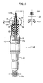
- Fig. 1 is a partial exploded view of a hydraulic shock absorber.
- Fig. 2 is an enlarged view of a portion of the hydraulic shock absorber which is indicated by an arrow 2 in Fig. 1.
- Fig. 3 is a view as viewed in a direction indicated by an arrow 3 in Fig. 2.
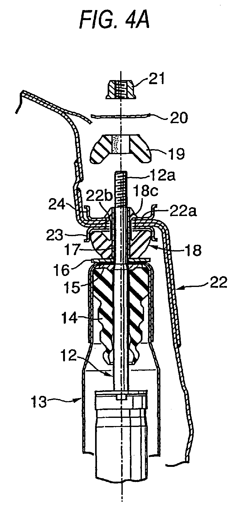
- Figs. 4A and 4B are drawings showing operations carried out when mounting the hydraulic shock absorber.
- Fig. 5 is a drawing showing a state in which the hydraulic shock absorber has completely been mounted.
- a hydraulic shock absorber SA which suspends a wheel of an automotive vehicle from a vehicle body includes a hydraulic cylinder 11 having hydraulic fluid sealed in the interior thereof and a rod 12 which protrudes telescopically from an upper end of the hydraulic cylinder 11.
- a mounting portion 11a at a lower end of the hydraulic cylinder is connected to a knuckle (or a suspension arm), not shown, which supports the wheel, via a rubber bushing.
- a bottom wall 13a of a bottomed cylindrical outer tube 13 is fixed to an intermediate portion of the rod 12 protruding from the hydraulic cylinder 11, and the outer tube 13 covers a lower part of the rod 12 and an upper part of the hydraulic cylinder 11.
- a bump stop rubber 14 is fixed to an outer circumference of the rod 12 covered by the outer tube 13.
- the bump stop rubber 14 abuts with a bump stop plate 15 provided on a lower side of the bottom wall 13a of the outer tube 13 at an upper end thereof.
- the bump stop rubber 14 also faces at a lower end thereof a load bearing surface 11b at the upper end of the hydraulic cylinder 11 with a predetermined distance being provided therebetween.
- a washer 16 and a collar 17 fit on the rod 12 which protrudes upwardly from the outer tube 13, and a lower damper mount bushing 18 fits on the collar 17.
- the collar 17 is fixed to the rod 12 by crimping, and the lower damper mount bushing 18 is supported on the collar 17 by virtue of friction force resulting from its own resiliency.
- an upper damper mount bushing 19 and a washer 20 are fit on the upper end of the rod 12, and the rod 12 is then fastened to the vehicle body with a nut 21 which thread fits on external ridges or threads 12a formed on the rod 12.
- the lower damper mount bushing 18 has a main body portion 18a, a thin tubular portion 18b and locking portions 18c.
- the main body portion 18a has a cup-like shape which is made to open upwardly.
- the thin tubular portion 18b extends upwardly from the main body portion 18a to fit on an outer circumference of the collar 17.
- the locking portions 18c are formed integrally with an upper end of the tubular portion 18b.
- a plurality of locking portions 18c (six in this embodiment) extend radially from the tubular portion 18b and are provided circumferentially at regular intervals, each being formed into a hook-like shape which is pointed upwardly.
- the upper damper mount bushing 19 is a member which is formed into a vertically symmetrical shape with the main body portion 18a of the lower damper mount bushing 18, but the upper damper mount bushing 19 does not have portions corresponding to the tubular portion 18b and the locking portions 18c.
- a mounting hole 22b is formed in an upper wall 22a of a wheel house 22 to which the upper end portion of the hydraulic shock absorber SA is mounted.
- a lower damper mount bushing support seat 23 is welded to a lower side of the mounting hole 22b, whereas an upper damper mount bushing support seat 24 is welded to an upper side of the mounting hole 22b.
- An inside diameter of the mounting hole 22b is set larger than an outside diameter of the tubular portion 18b of the lower damper mount bushing 18.
- the upper end of the rod 12 of the hydraulic shock absorber SA is inserted from below into the mounting hole 22b in the upper wall 22a of the wheel house 22 with the washer 16, the collar 17 and the lower damper mount bushing 18 being assembled to the rod 12.
- the locking portions 18c of the lower damper mount bushing 18 deform resiliently to pass through the mounting hole 22b and protrude above the mounting hole 22b, as shown in Fig. 4B.
- the rod 12 is prevented from coming off the mounting hole 22b to fall by bringing the locking portions 18c into engagement with the upper side of the mounting hole 22b even if the hydraulic shock absorber SA is not retained with the special fixture in the interior of the wheel house 22. Therefore, the workability in assembling the hydraulic shock absorber SA to the vehicle body can be improved remarkably.
- the upper damper mount bushing 19 and the washer 20 are caused to fit on the upper end of the rod 12 from above, outside the wheel house 22, and the nut 21 is thread fit on the external ridges or threads 12a formed on the rod 12 and is then tightened.
- the lower damper mount bushing 18 supported by the lower damper mount bushing support seat 23 at the upper side thereof and the upper damper mount bushing 19 supported on the upper damper mount bushing support seat 24 at the lower side thereof are compressed vertically, resulting in an assembled condition as shown in Fig. 5.
- the compression amount of the. lower damper mount bushing 18 and the upper damper mount bushing 19 is restricted to a predetermined magnitude through the abutment of the upper washer 20 with the collar 17.
- the shape and number of locking portions 18c of the lower damper mount bushing 18 are not limited to those described in the embodiment and can be modified appropriately.That is, the locking portions 18c can be configured in any shape or number as long as they are operable to at least temporarily hold the absorber during a mounting procedure.
- the temporarily fastening locking-portions are integrally formed on the resilient body fixed to the rod protruding telescopically from the upper end of the hydraulic cylinder and the locking portions are brought into engagement with the mounting hole in the upper wall of the wheel house, even when the hand is removed from the hydraulic cylinder with the rod being inserted into the mounting hole, there is no risk that the rod comes off the mounting hole to fall. Consequently, this obviates the necessity of retaining the hydraulic shock absorber with a special fixture in the interior of the wheel house while the nut is screwed onto the distal end of the rod to thereby fasten it to the upper wall of the wheel house; the workability being thereby improved remarkably.
- the resilient body since the resilient body has the tubular portion which fits on the outer circumference of the rod so as to be inserted into the mounting hole and the locking portions are integrally formed on the upper end of the tubular portion, a pre-compression can be imparted to the resilient body by compressing the tubular portion at the time of fastening with the nut, this being able to contribute to the improvement in response of the suspension.
- An upper portion of a rod protruding telescopically from an upper end of a hydraulic cylinder of a hydraulic shock absorber which suspends a wheel from a vehicle body is inserted from below into a mounting hole in an upper wall of a wheel house, and with a lower portion and an upper portion of the mounting hole being held by a lower damper mount bushing and an upper damper mount portion, respectively, a nut is then screwed on the upper portion of the rod to thereby fasten the rod to the upper wall of the wheel house.
- a temporarily fastening locking portion which is brought into engagement with the mounting hole in the wheel house to prevent the fall of the hydraulic shock absorber is integrally formed on the lower damper mount bushing fixed to the rod.
Landscapes
- Engineering & Computer Science (AREA)
- Mechanical Engineering (AREA)
- General Engineering & Computer Science (AREA)
- Fluid-Damping Devices (AREA)
- Vehicle Body Suspensions (AREA)
Abstract
Description
Claims (6)
- A hydraulic shock absorber mounting structure comprising:wherein the resilient body (18) includes a locking portion (18c) which is brought into engagement with a mounting hole (22b) of the vehicle body and is operable to prevent the hydraulic shock absorber (SA) from falling out of the mounting hole (22b) after engagement of the locking portion (18c) with the mounting hole (22b).a hydraulic shock absorber (SA) having a hydraulic cylinder (11), and a rod (12) protruding telescopically from the hydraulic cylinder (11);a fastening member (21) for fastening the hydraulic shock absorber (SA) to a vehicle body (22); anda resilient body (18), at least a portion thereof disposed between the hydraulic shock absorber (SA) and the vehicle body (22) when the hydraulic shock absorber (SA) is mounted to the vehicle body (22),
- A hydraulic shock absorber mounting structure as set forth in Claim 1, wherein the fastening member includes a nut (21) for fastening the rod (12) to the vehicle body (22) after engagement of the locking portion (18c) with the mounting hole (22b) of the vehicle body (22).
- A hydraulic shock absorber mounting structure as set forth in Claim 1, wherein the resilient body (18) further includes a tubular portion (18b) operable to be fit on an outer circumference of the rod (12) and being integrally formed with the locking portion (18c)at an upper end thereof so that when the rod (12) is inserted from below into the mounting hole (22b) of the vehicle body (22), the tubular portion (18b) is inserted into the mounting hole (22b) and the locking portion (18c) is protruded from and brought into.engagement with the mounting hole (22b) of the vehicle body (22).
- A hydraulic shock absorber mounting structure as set forth in Claim 3, wherein the locking portion (18c) includes a plurality of locking parts (18c...)which extend radially from the tubular portion (18b) and are provided circumferentially at regular intervals.
- A hydraulic shock absorber mounting structure as set forth in Claim 1, wherein the locking portion (18c) has a hook-like shape.
- A hydraulic shock absorber mounting structure as set forth in Claim 3, wherein the locking portion (18c) includes a plurality of locking parts (18c...)which extend radially from the tubular portion (18b) and are provided circumferentially at regular intervals, each of the locking parts being formed into a hook-like shape which is pointed upwardly.
Applications Claiming Priority (2)
| Application Number | Priority Date | Filing Date | Title |
|---|---|---|---|
| JP2002253576A JP4188033B2 (en) | 2002-08-30 | 2002-08-30 | Hydraulic shock absorber mounting structure |
| JP2002253576 | 2002-08-30 |
Publications (3)
| Publication Number | Publication Date |
|---|---|
| EP1393936A2 true EP1393936A2 (en) | 2004-03-03 |
| EP1393936A3 EP1393936A3 (en) | 2004-09-01 |
| EP1393936B1 EP1393936B1 (en) | 2009-10-28 |
Family
ID=31492646
Family Applications (1)
| Application Number | Title | Priority Date | Filing Date |
|---|---|---|---|
| EP03018585A Expired - Lifetime EP1393936B1 (en) | 2002-08-30 | 2003-08-18 | Upper mount assembly for a suspension damper |
Country Status (5)
| Country | Link |
|---|---|
| US (1) | US7066456B2 (en) |
| EP (1) | EP1393936B1 (en) |
| JP (1) | JP4188033B2 (en) |
| CN (1) | CN1257352C (en) |
| DE (1) | DE60329813D1 (en) |
Cited By (4)
| Publication number | Priority date | Publication date | Assignee | Title |
|---|---|---|---|---|
| EP1721810A3 (en) * | 2005-05-13 | 2007-07-25 | HONDA MOTOR CO., Ltd. | Automotive body structure |
| EP1862336A1 (en) * | 2006-06-03 | 2007-12-05 | Bayerische Motoren Werke Aktiengesellschaft | Support bearing for a suspension strut or similar of a vehicle |
| EP2143972A4 (en) * | 2007-04-06 | 2011-01-05 | Nok Corp | Bump stopper |
| FR3046569A1 (en) * | 2016-01-13 | 2017-07-14 | Peugeot Citroen Automobiles Sa | DEVICE FOR HIGHLY ATTACHING A SUSPENSION DAMPER OF A WHEEL OF A MOTOR VEHICLE |
Families Citing this family (36)
| Publication number | Priority date | Publication date | Assignee | Title |
|---|---|---|---|---|
| US6974766B1 (en) * | 1998-10-01 | 2005-12-13 | Applied Materials, Inc. | In situ deposition of a low κ dielectric layer, barrier layer, etch stop, and anti-reflective coating for damascene application |
| US6620723B1 (en) | 2000-06-27 | 2003-09-16 | Applied Materials, Inc. | Formation of boride barrier layers using chemisorption techniques |
| US7101795B1 (en) | 2000-06-28 | 2006-09-05 | Applied Materials, Inc. | Method and apparatus for depositing refractory metal layers employing sequential deposition techniques to form a nucleation layer |
| US7732327B2 (en) | 2000-06-28 | 2010-06-08 | Applied Materials, Inc. | Vapor deposition of tungsten materials |
| US7964505B2 (en) | 2005-01-19 | 2011-06-21 | Applied Materials, Inc. | Atomic layer deposition of tungsten materials |
| US7405158B2 (en) | 2000-06-28 | 2008-07-29 | Applied Materials, Inc. | Methods for depositing tungsten layers employing atomic layer deposition techniques |
| US6936538B2 (en) | 2001-07-16 | 2005-08-30 | Applied Materials, Inc. | Method and apparatus for depositing tungsten after surface treatment to improve film characteristics |
| US6551929B1 (en) * | 2000-06-28 | 2003-04-22 | Applied Materials, Inc. | Bifurcated deposition process for depositing refractory metal layers employing atomic layer deposition and chemical vapor deposition techniques |
| US7211144B2 (en) | 2001-07-13 | 2007-05-01 | Applied Materials, Inc. | Pulsed nucleation deposition of tungsten layers |
| US20070009658A1 (en) * | 2001-07-13 | 2007-01-11 | Yoo Jong H | Pulse nucleation enhanced nucleation technique for improved step coverage and better gap fill for WCVD process |
| TW581822B (en) | 2001-07-16 | 2004-04-01 | Applied Materials Inc | Formation of composite tungsten films |
| US20030029715A1 (en) | 2001-07-25 | 2003-02-13 | Applied Materials, Inc. | An Apparatus For Annealing Substrates In Physical Vapor Deposition Systems |
| US9051641B2 (en) | 2001-07-25 | 2015-06-09 | Applied Materials, Inc. | Cobalt deposition on barrier surfaces |
| JP2005504885A (en) | 2001-07-25 | 2005-02-17 | アプライド マテリアルズ インコーポレイテッド | Barrier formation using a novel sputter deposition method |
| US8110489B2 (en) | 2001-07-25 | 2012-02-07 | Applied Materials, Inc. | Process for forming cobalt-containing materials |
| US20090004850A1 (en) | 2001-07-25 | 2009-01-01 | Seshadri Ganguli | Process for forming cobalt and cobalt silicide materials in tungsten contact applications |
| US6936906B2 (en) | 2001-09-26 | 2005-08-30 | Applied Materials, Inc. | Integration of barrier layer and seed layer |
| TW589684B (en) * | 2001-10-10 | 2004-06-01 | Applied Materials Inc | Method for depositing refractory metal layers employing sequential deposition techniques |
| US6911391B2 (en) | 2002-01-26 | 2005-06-28 | Applied Materials, Inc. | Integration of titanium and titanium nitride layers |
| US6833161B2 (en) * | 2002-02-26 | 2004-12-21 | Applied Materials, Inc. | Cyclical deposition of tungsten nitride for metal oxide gate electrode |
| US7279432B2 (en) | 2002-04-16 | 2007-10-09 | Applied Materials, Inc. | System and method for forming an integrated barrier layer |
| US6838125B2 (en) * | 2002-07-10 | 2005-01-04 | Applied Materials, Inc. | Method of film deposition using activated precursor gases |
| US7211508B2 (en) * | 2003-06-18 | 2007-05-01 | Applied Materials, Inc. | Atomic layer deposition of tantalum based barrier materials |
| US7077371B1 (en) * | 2004-05-26 | 2006-07-18 | Kroeker Kent L | Shock absorber mounting assembly |
| DE102004039734A1 (en) * | 2004-08-17 | 2006-02-23 | Zf Friedrichshafen Ag | Bearing for a vibration damper |
| JP4138715B2 (en) * | 2004-08-23 | 2008-08-27 | 本田技研工業株式会社 | Damper mounting structure |
| US7429402B2 (en) * | 2004-12-10 | 2008-09-30 | Applied Materials, Inc. | Ruthenium as an underlayer for tungsten film deposition |
| KR101019293B1 (en) * | 2005-11-04 | 2011-03-07 | 어플라이드 머티어리얼스, 인코포레이티드 | Plasma-Enhanced Atomic Layer Deposition Apparatus and Method |
| WO2008005892A2 (en) * | 2006-06-30 | 2008-01-10 | Applied Materials, Inc. | Nanocrystal formation |
| JP5219718B2 (en) * | 2008-09-30 | 2013-06-26 | 株式会社ブリヂストン | In-wheel motor system |
| CN101774410B (en) * | 2010-03-04 | 2012-10-24 | 北汽福田汽车股份有限公司 | Method for producing automotive frame assembly |
| WO2013061809A1 (en) * | 2011-10-28 | 2013-05-02 | 本田技研工業株式会社 | Mount structure for vehicle damper and mount installation method for vehicle damper |
| JP2015013542A (en) * | 2013-07-04 | 2015-01-22 | トヨタ自動車株式会社 | Vehicle |
| FR3054806B1 (en) * | 2016-08-03 | 2019-11-01 | Vibracoustic Nantes Sas | SUPERIOR SUSPENSION SUPPORT COMPRISING A LOCKING MEMBER IN RELATION TO A VEHICLE BODY, AN ASSEMBLY COMPRISING SUCH A SUPPORT, AND A METHOD OF ASSEMBLING SUCH A SUPPORT WITH A VEHICLE BODY |
| DE102017205091A1 (en) * | 2017-03-27 | 2018-09-27 | Bayerische Motoren Werke Aktiengesellschaft | Support bearing of a vibration damper in the suspension of a vehicle |
| US11884359B2 (en) * | 2022-02-25 | 2024-01-30 | Sram, Llc | Bicycle suspension components |
Family Cites Families (10)
| Publication number | Priority date | Publication date | Assignee | Title |
|---|---|---|---|---|
| US3449799A (en) * | 1967-06-01 | 1969-06-17 | Chrysler Corp | Fastener for connecting apertured structure to another structure |
| JPS5954233A (en) | 1982-09-21 | 1984-03-29 | Nec Corp | Manufacture of hybrid integrated circuit |
| DE3935755A1 (en) * | 1988-10-28 | 1990-05-10 | Mazda Motor | SUSPENSION SYSTEM FOR MOTOR VEHICLES |
| US4958849A (en) | 1989-06-19 | 1990-09-25 | Saturn Corporation | Mounting assembly and method for a damper |
| US5326082A (en) * | 1992-06-10 | 1994-07-05 | Bridgestone/Firestone, Inc. | Self locking, snap mounted attachment device |
| DE4440030A1 (en) * | 1994-11-10 | 1996-05-15 | Fichtel & Sachs Ag | Vibration damper location to vehicle body |
| US5628388A (en) | 1995-07-11 | 1997-05-13 | Fried. Krupp Ag Hoesch-Krupp | Hydraulic shock absorber or spring leg for motor vehicles |
| US5788262A (en) * | 1995-12-19 | 1998-08-04 | Chrysler Corporation | Rear suspension strut upper mount |
| DE10018058B4 (en) | 2000-04-12 | 2017-12-28 | Volkswagen Ag | Mounting aid for a strut |
| JP3740973B2 (en) * | 2000-10-25 | 2006-02-01 | 東海ゴム工業株式会社 | Dust cover manufacturing method and shock absorber |
-
2002
- 2002-08-30 JP JP2002253576A patent/JP4188033B2/en not_active Expired - Lifetime
-
2003
- 2003-08-12 US US10/639,797 patent/US7066456B2/en not_active Expired - Fee Related
- 2003-08-18 EP EP03018585A patent/EP1393936B1/en not_active Expired - Lifetime
- 2003-08-18 DE DE60329813T patent/DE60329813D1/en not_active Expired - Lifetime
- 2003-08-29 CN CNB031560814A patent/CN1257352C/en not_active Expired - Fee Related
Cited By (4)
| Publication number | Priority date | Publication date | Assignee | Title |
|---|---|---|---|---|
| EP1721810A3 (en) * | 2005-05-13 | 2007-07-25 | HONDA MOTOR CO., Ltd. | Automotive body structure |
| EP1862336A1 (en) * | 2006-06-03 | 2007-12-05 | Bayerische Motoren Werke Aktiengesellschaft | Support bearing for a suspension strut or similar of a vehicle |
| EP2143972A4 (en) * | 2007-04-06 | 2011-01-05 | Nok Corp | Bump stopper |
| FR3046569A1 (en) * | 2016-01-13 | 2017-07-14 | Peugeot Citroen Automobiles Sa | DEVICE FOR HIGHLY ATTACHING A SUSPENSION DAMPER OF A WHEEL OF A MOTOR VEHICLE |
Also Published As
| Publication number | Publication date |
|---|---|
| US20040041320A1 (en) | 2004-03-04 |
| EP1393936B1 (en) | 2009-10-28 |
| CN1495371A (en) | 2004-05-12 |
| CN1257352C (en) | 2006-05-24 |
| JP2004092753A (en) | 2004-03-25 |
| EP1393936A3 (en) | 2004-09-01 |
| DE60329813D1 (en) | 2009-12-10 |
| US7066456B2 (en) | 2006-06-27 |
| JP4188033B2 (en) | 2008-11-26 |
Similar Documents
| Publication | Publication Date | Title |
|---|---|---|
| EP1393936B1 (en) | Upper mount assembly for a suspension damper | |
| US5487535A (en) | Suspension strut metal-to-metal jounce stop | |
| US4810003A (en) | Quick connect strut mount | |
| US5275389A (en) | Jounce bumper and dust shield subassembly for a suspension damper | |
| EP1681180B1 (en) | Strut mount | |
| US6616160B2 (en) | Strut mount | |
| US8979081B2 (en) | Tubular vibration-damping mount | |
| US5628388A (en) | Hydraulic shock absorber or spring leg for motor vehicles | |
| US10363789B2 (en) | Top mount assembly with bushing having integral anti-vibration feature | |
| US6341678B1 (en) | Strut | |
| JP3695153B2 (en) | Anti-vibration support device for coil spring | |
| JPH04321807A (en) | Mounting bracket for cylindrical containers | |
| KR101196072B1 (en) | Top fasteners for McPherson struts | |
| CN100436173C (en) | Spring strut mounting for a vehicle wheel | |
| US20060049015A1 (en) | Automatic nut running to torque without the possibility of slip | |
| JP2587050Y2 (en) | Vehicle side mounting structure of strut type suspension device | |
| JPH0139202Y2 (en) | ||
| CA2216757A1 (en) | Elastocell body mount | |
| JP2002155983A (en) | Mounting structure of hydraulic shock absorber in vehicle suspension | |
| JP2000346118A (en) | Strut mount insulator | |
| KR20010054640A (en) | Strut mounting of suspension system for a motor vehicle | |
| KR20080106654A (en) | Air suspension system | |
| JP4658398B2 (en) | Strut mount | |
| KR200143939Y1 (en) | Supporting structure of bumper rubber for shock absorber | |
| JP2002266916A (en) | Anti-vibration bush structure for automobiles |
Legal Events
| Date | Code | Title | Description |
|---|---|---|---|
| PUAI | Public reference made under article 153(3) epc to a published international application that has entered the european phase |
Free format text: ORIGINAL CODE: 0009012 |
|
| AK | Designated contracting states |
Kind code of ref document: A2 Designated state(s): AT BE BG CH CY CZ DE DK EE ES FI FR GB GR HU IE IT LI LU MC NL PT RO SE SI SK TR |
|
| AX | Request for extension of the european patent |
Extension state: AL LT LV MK |
|
| PUAL | Search report despatched |
Free format text: ORIGINAL CODE: 0009013 |
|
| AK | Designated contracting states |
Kind code of ref document: A3 Designated state(s): AT BE BG CH CY CZ DE DK EE ES FI FR GB GR HU IE IT LI LU MC NL PT RO SE SI SK TR |
|
| AX | Request for extension of the european patent |
Extension state: AL LT LV MK |
|
| RIC1 | Information provided on ipc code assigned before grant |
Ipc: 7B 60G 13/00 A Ipc: 7B 60G 15/06 B |
|
| 17P | Request for examination filed |
Effective date: 20041022 |
|
| AKX | Designation fees paid |
Designated state(s): DE FR GB |
|
| 17Q | First examination report despatched |
Effective date: 20071008 |
|
| GRAP | Despatch of communication of intention to grant a patent |
Free format text: ORIGINAL CODE: EPIDOSNIGR1 |
|
| GRAS | Grant fee paid |
Free format text: ORIGINAL CODE: EPIDOSNIGR3 |
|
| GRAA | (expected) grant |
Free format text: ORIGINAL CODE: 0009210 |
|
| AK | Designated contracting states |
Kind code of ref document: B1 Designated state(s): DE FR GB |
|
| REG | Reference to a national code |
Ref country code: GB Ref legal event code: FG4D |
|
| REF | Corresponds to: |
Ref document number: 60329813 Country of ref document: DE Date of ref document: 20091210 Kind code of ref document: P |
|
| PLBE | No opposition filed within time limit |
Free format text: ORIGINAL CODE: 0009261 |
|
| STAA | Information on the status of an ep patent application or granted ep patent |
Free format text: STATUS: NO OPPOSITION FILED WITHIN TIME LIMIT |
|
| 26N | No opposition filed |
Effective date: 20100729 |
|
| PGFP | Annual fee paid to national office [announced via postgrant information from national office to epo] |
Ref country code: FR Payment date: 20100824 Year of fee payment: 8 |
|
| PGFP | Annual fee paid to national office [announced via postgrant information from national office to epo] |
Ref country code: GB Payment date: 20100818 Year of fee payment: 8 |
|
| PGFP | Annual fee paid to national office [announced via postgrant information from national office to epo] |
Ref country code: DE Payment date: 20110810 Year of fee payment: 9 |
|
| GBPC | Gb: european patent ceased through non-payment of renewal fee |
Effective date: 20110818 |
|
| REG | Reference to a national code |
Ref country code: FR Ref legal event code: ST Effective date: 20120430 |
|
| PG25 | Lapsed in a contracting state [announced via postgrant information from national office to epo] |
Ref country code: FR Free format text: LAPSE BECAUSE OF NON-PAYMENT OF DUE FEES Effective date: 20110831 Ref country code: GB Free format text: LAPSE BECAUSE OF NON-PAYMENT OF DUE FEES Effective date: 20110818 |
|
| PG25 | Lapsed in a contracting state [announced via postgrant information from national office to epo] |
Ref country code: DE Free format text: LAPSE BECAUSE OF NON-PAYMENT OF DUE FEES Effective date: 20130301 |
|
| REG | Reference to a national code |
Ref country code: DE Ref legal event code: R119 Ref document number: 60329813 Country of ref document: DE Effective date: 20130301 |