EP1393682B1 - Détermination de la dose de rayonnement minimale pour obtenir une image tomographique par ordinateur - Google Patents
Détermination de la dose de rayonnement minimale pour obtenir une image tomographique par ordinateur Download PDFInfo
- Publication number
- EP1393682B1 EP1393682B1 EP03254491A EP03254491A EP1393682B1 EP 1393682 B1 EP1393682 B1 EP 1393682B1 EP 03254491 A EP03254491 A EP 03254491A EP 03254491 A EP03254491 A EP 03254491A EP 1393682 B1 EP1393682 B1 EP 1393682B1
- Authority
- EP
- European Patent Office
- Prior art keywords
- noise
- image
- data
- simulated
- patient image
- Prior art date
- Legal status (The legal status is an assumption and is not a legal conclusion. Google has not performed a legal analysis and makes no representation as to the accuracy of the status listed.)
- Expired - Fee Related
Links
Images

Classifications
-
- G—PHYSICS
- G06—COMPUTING; CALCULATING OR COUNTING
- G06T—IMAGE DATA PROCESSING OR GENERATION, IN GENERAL
- G06T11/00—2D [Two Dimensional] image generation
- G06T11/003—Reconstruction from projections, e.g. tomography
- G06T11/008—Specific post-processing after tomographic reconstruction, e.g. voxelisation, metal artifact correction
-
- A—HUMAN NECESSITIES
- A61—MEDICAL OR VETERINARY SCIENCE; HYGIENE
- A61B—DIAGNOSIS; SURGERY; IDENTIFICATION
- A61B6/00—Apparatus for radiation diagnosis, e.g. combined with radiation therapy equipment
-
- A—HUMAN NECESSITIES
- A61—MEDICAL OR VETERINARY SCIENCE; HYGIENE
- A61B—DIAGNOSIS; SURGERY; IDENTIFICATION
- A61B6/00—Apparatus for radiation diagnosis, e.g. combined with radiation therapy equipment
- A61B6/58—Testing, adjusting or calibrating apparatus or devices for radiation diagnosis
- A61B6/582—Calibration
- A61B6/583—Calibration using calibration phantoms
-
- Y—GENERAL TAGGING OF NEW TECHNOLOGICAL DEVELOPMENTS; GENERAL TAGGING OF CROSS-SECTIONAL TECHNOLOGIES SPANNING OVER SEVERAL SECTIONS OF THE IPC; TECHNICAL SUBJECTS COVERED BY FORMER USPC CROSS-REFERENCE ART COLLECTIONS [XRACs] AND DIGESTS
- Y10—TECHNICAL SUBJECTS COVERED BY FORMER USPC
- Y10S—TECHNICAL SUBJECTS COVERED BY FORMER USPC CROSS-REFERENCE ART COLLECTIONS [XRACs] AND DIGESTS
- Y10S378/00—X-ray or gamma ray systems or devices
- Y10S378/901—Computer tomography program or processor
Definitions
- the present disclosure relates generally imaging systems and, more particularly, to improving the dose efficiency for an imaging system through a method and system for image simulation at lower doses.
- an x-ray source projects a fan-shaped beam which is collimated to lie within an X-Y plane of a Cartesian coordinate system, wherein the X-Y plane is generally referred to as an "imaging plane".
- An array of radiation detectors wherein each radiation detector includes a detector element, are within the CT system so as to received this fan-shaped beam.
- An object such as a patient, is disposed within the imaging plane so as to be subjected to the x-ray beam wherein the x-ray beam passes through the object. As the x-ray beam passes through the object being imaged, the x-ray beam becomes attenuated before impinging upon the array of radiation detectors.
- the intensity of the attenuated beam radiation received at the detector array is responsive to the attenuation of the x-ray beam by the object, wherein each detector element produces a separate electrical signal responsive to the beam attenuation at the detector element location.
- These electrical signals are referred to as x-ray attenuation measurements.
- the x-ray source and the detector array may be rotated, with a gantry within the imaging plane, around the object to be imaged so that the angle at which the x-ray beam intersects the object constantly changes.
- a group of x-ray attenuation measurements, i.e., projection data, from the detector array at one gantry angle is referred to as a "view”.
- a "scan" of the object comprises a set of views made at different gantry angles during one revolution of the x-ray source and the detector array.
- the projection data is processed so as to construct an image that corresponds to a two-dimensional slice taken through the object.
- filtered back-projection technique One method for reconstructing an image from a set of projection data is referred to as the "filtered back-projection technique”.
- This process converts the attenuation measurements from a scan into discrete integers, ranging from -1024 to +3071, called “CT numbers” or “Hounsfield Units” (HU). These HU's are used to control the brightness of a corresponding pixel on a cathode ray tube or a computer screen display in a manner responsive to the attenuation measurements.
- an attenuation measurement for air may convert into an integer value of -1000 HU's (corresponding to a dark pixel) and an attenuation measurement for very dense bone matter may convert into an integer value of +2000 (corresponding to a bright pixel), whereas an attenuation measurement for water may convert into an integer value of 0 HU's (corresponding to a gray pixel).
- This integer conversion, or "scoring" allows a physician or a technician to determine the density of matter based on the intensity of the computer display.
- imaging systems such as the CT imaging system
- CT scans account for only about 2% to 3% of medical examinations using imaging systems. However, they account for 30% to 50% of the population radiation dose from these procedures. Given that exposure to greater than average amounts of radiation is known to cause health problems, there is concern within the medical community that a patient may be over exposed. As such, there is a continuing but increasingly limited effort to reduce the amount of patient exposure by improving the imaging dose efficiency. This effort includes researchers investigating and determining the minimum dose required to obtain the image quality necessary to make an accurate and confident diagnosis for a given clinical application. As patient dose is decreased, the image noise is increased, making lesions more difficult to detect.
- a reference object such as a patient
- a reference object In order obtain the data needed to find the minimum dose necessary to make a confident diagnosis a reference object, such as a patient, must undergo multiple scans at different dose levels. Unfortunately, this may be considered unethical, inappropriate and potentially detrimental to the patient(s) being scanned for these purposes. Accordingly, it is desirable to be able to determine minimum dose information without the need for exposing a patient to excessive radiation doses.
- the method includes obtaining image data from an actual patient image and generating simulated noise data. The image data is then combined with the simulated noise data to create the simulated patient image.
- scan data from the actual patient image is combined with the generated simulated noise data to create pre-image data, and the pre-image data is then reconstructed to create simulated image data.
- a set of individual noise pattern images for each a plurality of phantom objects is created. At least one of the individual noise pattern images is selected for combination with the actual patient image. The at least one selected individual noise pattern image is then combined with the actual patient image, thereby creating the simulated patient image.
- a method for generating a simulated computer tomography (CT) patient image includes obtaining image data from an actual CT patient image taken at a first radiation dose, and generating simulated noise data. The image data is then combined with the simulated noise data to create the simulated patient image, wherein the simulated image simulates the actual CT patient image taken at a second, reduced radiation dose with respect to the first radiation dose.
- CT computer tomography
- an imaging system in another aspect, includes a gantry having an x-ray source and a radiation detector array, wherein the gantry defines a patient cavity and wherein the x-ray source and the radiation detector array are rotatingly associated with the gantry so as to be separated by the patient cavity.
- a patient support structure is movingly associated with the gantry so as to allow communication with the patient cavity.
- a processing device is used for obtaining image data from an actual patient image.
- the imaging system further includes means for generating simulated noise data, and means for combining the image data with the simulated noise data to create a simulated patient image.
- a storage medium includes a machine readable computer program code for generating a simulated patient image, and instructions for causing a computer to implement a method.
- the method includes obtaining image data from an actual patient image, generating simulated noise data and combining the image data with the simulated noise data to create the simulated patient image.
- a computer data signal includes code configured to cause a processor to implement a method for generating a simulated patient image.
- the method includes obtaining image data from an actual patient image, generating simulated noise data and combining the image data with the simulated noise data to create the simulated patient image.
- FIG. 1 a representative CT imaging system 1 suitable for practicing the present invention embodiments.
- the system 1 includes a gantry 2 having an x-ray source 4, a radiation detector array 6, a patient support structure 8 and a patient cavity 10, wherein the x-ray source 4 and the radiation detector array 6 are opposingly disposed so as to be separated by the patient cavity 10.
- a patient 12 is shown disposed upon a patient support structure 8 which in turn is disposed within patient cavity 10.
- the X-ray source 4 projects an x-ray beam 14 toward radiation detector array 6 so as to pass through patient 12.
- the X-ray beam 14 is preferably collimated by a collimator (not shown) so as to lie within an X-Y plane of a Cartesian coordinate system referred to as an "imaging plane".
- the attenuated x-ray beam 16 is received by the radiation detector array .6.
- the radiation detector array 6 may include a plurality of detector elements 18, wherein each of the detector elements 18 receives an attenuated x-ray beam 16 and produces an electrical signal responsive to the intensity of attenuated x-ray beam 16.
- the x-ray source 4 and radiation detector array 6 are rotatingly disposed relative to the gantry 2 and the patient support structure 8, so as to allow x-ray source 4 and radiation detector array 6 to rotate around the patient support structure 8 when it is disposed within patient cavity 10.
- X-ray projection data is then obtained by rotating x-ray source 4 and radiation detector array 6 around patient 10 during a scan.
- the rotation and operation of the X-ray source 4 and radiation detector array 6 are controlled by a control mechanism 20 associated with the CT imaging system 1.
- control mechanism 20 includes an x-ray controller 22 in communication with x-ray source 4, a gantry motor controller 24, and a data acquisition system (DAS) 26 in communication with the radiation detector array 6.
- the x-ray controller 22 provides power and timing signals to x-ray source 4, gantry motor controller 24 controls the rotational speed and angular position of the x-ray source 4, while the radiation detector array 6 and DAS 26 receive the electrical signal data produced by detector elements 18, to be converted into digital signals for subsequent processing.
- the CT imaging system 1 also includes an image reconstruction device 28, a data storage device 30 and a processing device 32, wherein the processing device 32 further communicates with the image reconstruction device 28, the gantry motor controller 24, the x-ray controller 22 and the data storage device 30, as well as with an input device 34 and an output device 36.
- the CT imaging system 1 also features a table controller 38 in communication with the processing device 32 and the patient support structure 8, so as to control the position of the patient support structure 8 relative to patient cavity 10 .
- the patient 12 is situated upon then patient support structure 8, which is then positioned by an operator (via processing device 32) within the patient cavity 10.
- the gantry motor controller 24 is then operated via the processing device 32, thereby causing the x-ray source 4 and the radiation detector array 6 to rotate relative to patient 12.
- the X-ray controller 22 is operated via processing device 32 so as to cause x-ray source 4 to emit and project a collimated x-ray beam 14 toward radiation detector array 6 and hence toward patient 12.
- X-ray beam 14 passes through patient 12 so as to create an attenuated x-ray beam 16, which is received by radiation detector array 6.
- the detector elements 18 Upon receiving the attenuated x-ray beam 16, the detector elements 18 produce electrical signal data responsive to the intensity of the attenuated x-ray beam 16, thereafter and communicating this electrical signal data to the DAS 26.
- the DAS 26 then converts electrical signal data to digital signals and sends both the digital signals and the electrical signal data to the image reconstruction device 28 for high-speed image reconstruction.
- This image reconstruction information is then communicated to processing device 32, which stores the image in data storage device 30 and displays the digital signal as an image via output device 36.
- a method and system for simulation of a CT image at low doses Briefly stated, a patient is scanned once in the usual manner as prescribed by existing diagnostic clinical practice standards. Then, the patient's scan data is used to create images at simulated lower doses by the introduction of noise data therewith. As will be described hereinafter, in one embodiment the noise data is combined with the raw scan data, while in another embodiment, the noise data is combined with the image data. In either case, the both the image data and associated noise data are used to reconstruct an image (simulated image data) that simulates data obtained via a lower dose scan.
- Simulating patient images at lower radiation doses may be accomplished in at least two ways.
- One way to simulate patient images at lower radiation doses includes generating noise via a random number generator having a Poisson distribution and associating this noise with image data in order to simulate a lower dose (mA value) than that used for the scan. This advantageously allows the image data and associated noise data to be used to reconstruct an image (simulated image data) that simulates data obtained via a lower dose scan.
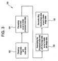
- a first embodiment of a method 100 for simulating patient images at lower radiation doses using imaging system 1 is shown and discussed.
- the embodiment associated with method 100 is characterized by generating noise via a random number generator having a Poisson distribution and associating this noise with image data in order to simulate a lower dose (mA value) than that used for the scan.
- the method 100 begins at block 102, where both the image data and noise data are obtained.
- the image data may be obtained via imaging system 1, wherein the image data includes image data sample elements and is responsive to patient 12.
- the noise data is preferably obtained via a random number generator having a Poisson distribution and preferably includes noise data sample elements.
- the noise data may also be generated using any signal generating device and/or method suitable to the desired end purpose.
- each image data sample element is the number of detected photons multiplied by a gain factor multiplier.
- the noise data is processed so as to create processed noise data, as shown in block 104. This is accomplished by multiplying the Poisson distributed noise from the random number generator for each image data sample element by the corresponding noise scale factor ⁇ , thereby creating processed noise data having processed noise data elements.
- the processed noise data is then associated with the image data to create pre-image data, as shown in block 106. This is accomplished by adding the processed noise data elements with the corresponding image data sample elements. Once this has been completed, the pre-image data is then reconstructed to produce simulated image data, as shown in block 108. This simulated image data may then be displayed as an image as if it were collected using an mA tube current value of ⁇ times the mA tube current of the original patient scan.
- ⁇ may be approximated by determining the maximum value of D for each projection for which a value of ⁇ has be predetermined to produce a constant value of ⁇ to be applied to the Poisson distributed noise.
- ⁇ is preferably determined empirically to match fit results, ⁇ may also be determined using any method and/or device suitable to the desired end purpose.
- non-quantum noise may also be observed in image data and may combine with the photon noise when the signal levels are low enough.
- One such source of non-quantum noise may be electronic noise generated via a DAS.
- the Poisson distributed noise P may be multiplied by an additional scaling factor N n to account for the contribution due to non-quantum noise. If the image data signal is small enough such that the non-quantum noise is significant, the scaling factor N n should be determined so as to increase the Poisson distributed noise ⁇ such that the total added noise compensates for the quantum noise as well as the non-quantum noise in the simulated image data.
- ⁇ is the amount of Poisson distributed noise to associated with a corresponding image data sample element as given above from equation (1)
- N n is the noise contribution due to non-quantum noise
- P is the Poisson distributed noise from the random number generator.
- the value of N n will be equal to unity or 1.
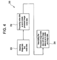
- image data and noise data are first obtained.
- the image data is preferably obtained via imaging system 1, wherein the image data includes image data sample elements and is responsive to patient 12.
- the noise data is this instance is preferably obtained by scanning a plurality of phantom objects for each bowtie filter and kV setting of imaging system 1.
- the noise data preferably includes a set of 10 (minimum) noise pattern images responsive to a variety of phantoms, a variety of bowtie filters, the scanning technique and a variety of emitter tube voltage levels.
- the noise data For example, to extract the noise data, two scans of a phantom object are performed and the obtained images are subtracted so as to obtain a raw noise pattern for each of the images. Any pixels that contain phantom edge structure after the subtraction are replaced with a random value having a standard deviation equivalent to that in the random area of the noise pattern.
- noise data and thus the noise pattern images
- These noise pattern images are preferably predetermined and include a sufficient number of individual noise pattern images so as to allow various combinations thereof to be used, thereby avoiding reusing the same combinations too frequently.
- the noise data is processed to create processed image noise data, as shown in block 204. This is accomplished by examining the stored noise pattern images so as to identify the noise pattern images that corresponds to a phantom shape and scan technique that best matches the physical shape of patient 12 and the scan technique employed to scan patient 12. Once the noise pattern images that best fit the patient and the scan technique have been determined, a predetermined number of selected noise pattern images are randomly selected so as to create processed noise data. Since noise adds as the square root of the sum of the squares, the noise images are scaled (i.e., multiplied) by the inverse square root of the number of noise images selected.
- the processed image noise data is associated with the patient image data to create a simulated image, as shown in block 206. This may be accomplished by adding the randomly selected noise pattern images to in order obtain a resultant noise pattern image. This resultant noise pattern image is interpolated to match the DFOV of the patient image and is then scaled by a scaling factor s , wherein the scaling factor s is determined to simulate a desired low dose image.
- the noise value of the original image ⁇ 0 may also be estimated by equating ⁇ 0 with the noise pattern of the selected phantom image wherein adjustments have been made to compensate for differences between the scanning technique used to obtain the original image and the scanning technique and processing used to obtain the selected phantom image.
- ⁇ 0 may be determined by summing the pixel data in the vertical and horizontal orientations and subsequently using a noise prediction strategy as described in U.S. Pat. Publication No. 2004/0032928 A1 .
- the above described embodiments advantageously allows for medical patients to be scanned only once in the usual manner as prescribed by current diagnostic clinical practice.
- patients do not receive any additional radiation exposure for research beyond what they would have received for a typical clinical diagnostic prescription.
- the patient's data may also be used to generate images at a simulated lower doses, researchers are able to study whether the patient dose exposure has any impact on the diagnostic outcome of the patient. As a result, patients do not have to be scanned multiple times at different doses for such clinical research.
- the disclosed simulation techniques may generally be applied in conjunction with any imaging system suitable to a desired diagnostic purpose, such as magnetic resonance imaging (MRI), ultrasound, X-Ray, CT and/or PET.
- the method embodiments of Figure 3 and/or Figure 4 may be implemented through processing device 32 operating in response to a computer program.
- the controller may include, but not be limited to, a processor(s), computer(s), memory, storage, register(s), timing, interrupt(s), communication interfaces, and input/output signal interfaces, as well as combinations comprising at least one of the foregoing.
- the controller may include signal input signal filtering to enable accurate sampling and conversion or acquisitions of such signals from communications interfaces.
- the embodiments that the of Figure 3 and/or Figure 4 may be implemented via a controller located remotely from processing device 32.
- the present invention can be embodied in the form of computer-implemented processes and apparatuses for practicing those processes.
- the present invention can also be embodied in the form of computer program code containing instructions embodied in tangible media, such as floppy diskettes, CD-ROMs, hard drives, or any other computer-readable storage medium, wherein, when the computer program code is loaded into and executed by a computer, the computer becomes an apparatus for practicing the invention.
- Existing systems having reprogrammable storage e.g., flash memory
- the present invention can also be embodied in the form of computer program code, for example, whether stored in a storage medium, loaded into and/or executed by a computer, or transmitted over some transmission medium, such as over electrical wiring or cabling, through fiber optics, or via electromagnetic radiation, wherein, when the computer program code is loaded into and executed by a computer, the computer becomes an apparatus for practicing the invention.
- computer program code segments configure the microprocessor to create specific logic circuits.
Claims (16)
- Procédé (100, 200) de génération d'une image de patient simulée, le procédé comprenant :l'obtention de données d'image à partir d'une image de patient réelle (102, 202) ;la génération de données de bruit simulé (104, 204) ;la combinaison desdites données d'image avec lesdites données de bruit simulé pour créer l'image de patient simulée (108, 206) ;la combinaison de données de balayage issues de ladite image de patient réelle avec lesdites données de bruit simulé générées pour créer des données de pré-image ;la reconstruction desdites données de pré-image pour créer des données d'image simulée ;dans lequel lesdites données de bruit simulé sont générées par un générateur de nombres aléatoires conformément à une loi de Poisson ;dans lequel des échantillons de données de balayage individuels issus desdites données de balayage sont combinés chacun avec une valeur de bruit aléatoire générée par ledit générateur de nombres aléatoires à loi de Poisson, caractérisé en ce que ladite valeur de bruit aléatoire est d'abord multipliée par un facteur de pondération pour produire une valeur de bruit aléatoire pondérée ; etledit facteur de pondération est déterminé selon l'équation :

dans laquelle α est ledit facteur de pondération, β est un facteur multiplicatif dont la valeur dépend du gain d'un système d'acquisition de données (DAS) (26) et des caractéristiques de traitement d'image, α est un facteur de réduction de courant de tube par rapport à un courant de tube auquel ladite image de patient réelle a été acquise, et D est un niveau de signal DAS pour un échantillon de données de balayage individuel correspondant. - Procédé (100) selon la revendication 1, dans lequel, en plus dudit facteur de pondération, chacune desdites valeurs de bruit aléatoire est en outre multipliée par un facteur multiplicatif de bruit électronique avant d'être combinée avec un échantillon de données de balayage individuel, ledit facteur multiplicatif de bruit électronique étant déterminé selon l'équation :

dans laquelle Nn est ledit facteur multiplicatif de bruit électronique dû à un bruit non quantique, α est ledit facteur de pondération, P est ladite valeur de bruit aléatoire générée par ledit générateur de nombres aléatoires à loi de Poisson, et σα est un écart type desdites données de bruit simulé générées à combiner avec ladite image de patient réelle. - Procédé (200) selon la revendication 1, comprenant en outre :la création d'un ensemble d'images de motif de bruit individuelles pour chaque objet fantôme parmi une pluralité d'objets fantômes ;la sélection d'au moins une desdites images de motif de bruit individuelles à combiner avec ladite image de patient réelle ; etla combinaison de ladite au moins une image de motif de bruit individuelle sélectionnée avec ladite image de patient réelle, pour ainsi créer l'image de patient simulée.
- Procédé (200) selon la revendication 3, dans lequel ladite sélection d'au moins une desdites images de motif de bruit individuelles est basée sur une morphologie de patient et une technique d'imagerie.
- Procédé (200) selon la revendication 3, dans lequel ladite au moins une desdites images de motif de bruit individuelles est sélectionnée aléatoirement.
- Procédé (200) selon la revendication 5, dans lequel si plus d'une seule desdites images de motif de bruit individuelles est sélectionnée, alors lesdites images de motif de bruit sont additionnées pour produire un motif de bruit résultant.
- Procédé (200) selon la revendication 6, dans lequel ledit motif de bruit combiné est multiplié par un facteur multiplicatif, s, déterminé selon l'équation :

avec
dans lesquelles σα est un écart type desdites données de bruit simulé générées à combiner avec ladite image de patient réelle, σ p est un écart type d'images de motif de bruit sélectionnées aléatoirement, interpolées et additionnées, σ f est un écart type désiré pour l'image de patient simulée, σ0 est un écart type de ladite image de patient réelle et α est un facteur de réduction de courant de tube par rapport à un courant de tube auquel ladite image de patient réelle a été acquise. - Procédé (200) selon la revendication 7, dans lequel lesdites images de motif de bruit sont multipliées par l'inverse de la racine carrée du nombre desdites images de motif de bruit sélectionnées.
- Système d'imagerie (1), comprenant :un portique (2) comprenant une source de rayons X (4) et une matrice de détecteurs de rayonnement (6), ledit portique (2) délimitant une cavité de patient (10) et ladite source de rayons X (4) et ladite matrice de détecteurs de rayonnement (6) étant associés de manière rotative audit portique (2) pour être séparés par ladite cavité de patient (10) ;une structure de support de patient (8) associée de manière mobile audit portique (2) pour permettre une communication avec ladite cavité de patient (10) ;un dispositif de traitement (32) pour obtenir des données d'image à partir d'une image de patient réelle ;un moyen de génération de données de bruit simulé ;un moyen de combinaison desdites données d'image avec lesdites données de bruit simulé pour créer une image de patient simulée ;un moyen de combinaison de données de balayage issues de ladite image de patient réelle avec lesdites données de bruit simulé générées pour créer des données de pré-image ;un moyen de reconstruction desdites données de pré-image pour créer des données d'image simulée ;dans lequel lesdites données de bruit simulé sont générées par un générateur de nombres aléatoires conformément à une loi de Poisson ;dans lequel des échantillons de données de balayage individuels issus desdites données de balayage sont combinés chacun avec une valeur de bruit aléatoire générée par ledit générateur de nombres aléatoires à loi de Poisson, caractérisé en ce que ladite valeur de bruit aléatoire est d'abord multipliée par un facteur de pondération pour produire une valeur de bruit aléatoire pondérée ; etledit facteur de pondération est déterminé selon l'équation :

dans laquelle α est ledit facteur de pondération, β est un facteur multiplicatif dont la valeur dépend du gain d'un système d'acquisition de données (DAS) (26) et des caractéristiques de traitement d'image, α est un facteur de réduction de courant de tube par rapport à un courant de tube auquel ladite image de patient réelle a été acquise, et D est un niveau de signal DAS pour un échantillon de données de balayage individuel correspondant. - Système d'imagerie (1) selon la revendication 9, dans lequel, en plus dudit facteur de pondération, chacune desdites valeurs de bruit aléatoire est en outre multipliée par un facteur multiplicatif de bruit électronique avant d'être combinée avec un échantillon de données de balayage individuel, ledit facteur multiplicatif de bruit électronique étant déterminé selon l'équation :

dans laquelle Nn est ledit facteur multiplicatif de bruit électronique dû à un bruit non quantique, α est ledit facteur de pondération, P est ladite valeur de bruit aléatoire générée par ledit générateur de nombres aléatoires à loi de Poisson, et σα est un écart type desdites données de bruit simulé générées à combiner avec ladite image de patient réelle. - Système d'imagerie (1) selon la revendication 9, comprenant en outre :un moyen de création d'un ensemble d'images de motif de bruit individuelles pour chaque objet fantôme parmi une pluralité d'objets fantômes ;un moyen de sélection d'au moins une desdites images de motif de bruit individuelles à combiner avec ladite image de patient réelle ; etun moyen de combinaison de ladite au moins une image de motif de bruit individuelle sélectionnée avec ladite image de patient réelle, pour ainsi créer l'image de patient simulée.
- Système d'imagerie (1) selon la revendication 11, dans lequel ledit moyen de sélection d'au moins une desdites images de motif de bruit individuelles est basé sur une morphologie de patient et une technique d'imagerie.
- Système d'imagerie (1) selon la revendication 11, dans lequel ladite au moins une desdites images de motif de bruit individuelles est sélectionnée aléatoirement.
- Système d'imagerie (1) selon la revendication 13, dans lequel si plus d'une seule desdites images de motif de bruit individuelles est sélectionnée, alors lesdites images de motif de bruit sont additionnées pour produire un motif de bruit résultant.
- Système d'imagerie (1) selon la revendication 14, dans lequel ledit motif de bruit combiné est multiplié par un facteur multiplicatif, s, déterminé selon l'équation :

avec
dans lesquelles σα est un écart type desdites données de bruit simulé générées à combiner avec ladite image de patient réelle, σ p est un écart type d'images de motif de bruit sélectionnées aléatoirement, interpolées et additionnées, σ f est un écart type désiré pour l'image de patient simulée, σ0 est un écart type de ladite image de patient réelle et α est un facteur de réduction de courant de tube par rapport à un courant de tube auquel ladite image de patient réelle a été acquise. - Système d'imagerie (1) selon la revendication 15, dans lequel lesdites images de motif de bruit sont multipliées par l'inverse de la racine carrée du nombre desdites images de motif de bruit sélectionnées.
Applications Claiming Priority (2)
| Application Number | Priority Date | Filing Date | Title |
|---|---|---|---|
| US10/064,586 US6829323B2 (en) | 2002-07-29 | 2002-07-29 | Method and system for low dose image simulation for imaging systems |
| US64586 | 2002-07-29 |
Publications (3)
| Publication Number | Publication Date |
|---|---|
| EP1393682A2 EP1393682A2 (fr) | 2004-03-03 |
| EP1393682A3 EP1393682A3 (fr) | 2007-05-30 |
| EP1393682B1 true EP1393682B1 (fr) | 2012-09-12 |
Family
ID=30769096
Family Applications (1)
| Application Number | Title | Priority Date | Filing Date |
|---|---|---|---|
| EP03254491A Expired - Fee Related EP1393682B1 (fr) | 2002-07-29 | 2003-07-18 | Détermination de la dose de rayonnement minimale pour obtenir une image tomographique par ordinateur |
Country Status (3)
| Country | Link |
|---|---|
| US (1) | US6829323B2 (fr) |
| EP (1) | EP1393682B1 (fr) |
| JP (1) | JP4344191B2 (fr) |
Families Citing this family (25)
| Publication number | Priority date | Publication date | Assignee | Title |
|---|---|---|---|---|
| US20030206662A1 (en) * | 2002-05-03 | 2003-11-06 | Avinash Gopal B. | Method and apparatus for improving perceived digital image quality |
| DE102004046441B8 (de) * | 2004-09-24 | 2006-07-06 | Siemens Ag | Verfahren zur Bildwiedergabe, insbesondere bei medizinischen Einzel- oder Serienaufnahmen |
| DE102005001681B4 (de) * | 2005-01-13 | 2007-10-11 | Siemens Ag | Verfahren zur Ermittlung von Aufnahmeparametern für eine medizinische Tomographieeinrichtung sowie zugehörige Vorrichtung |
| JP2006212308A (ja) * | 2005-02-07 | 2006-08-17 | Ge Medical Systems Global Technology Co Llc | 放射線断層撮影装置、放射線画像シミュレーション方法および画像シミュレーション装置 |
| JP4174487B2 (ja) * | 2005-03-24 | 2008-10-29 | アドバンスド・マスク・インスペクション・テクノロジー株式会社 | 画像補正方法 |
| EP1731100B9 (fr) * | 2005-06-06 | 2013-01-23 | Kabushiki Kaisha Toshiba | Appareil et système medical d'affichage d'images |
| JP2007014755A (ja) * | 2005-06-06 | 2007-01-25 | Toshiba Corp | 医用画像表示装置、医用画像生成プログラム、及びx線コンピュータ断層撮影装置 |
| JP5047945B2 (ja) * | 2006-04-04 | 2012-10-10 | 株式会社日立メディコ | X線ctスキャンシミュレータ装置、x線ct装置、及びx線ctスキャンシミュレータプログラム |
| US20080118128A1 (en) * | 2006-11-21 | 2008-05-22 | Thomas Louis Toth | Methods and systems for enhanced accuracy image noise addition |
| JP5006732B2 (ja) * | 2007-08-09 | 2012-08-22 | キヤノン株式会社 | 放射線撮影装置及びその制御方法 |
| DE102007046941B4 (de) * | 2007-09-28 | 2017-12-28 | Siemens Healthcare Gmbh | Verfahren zur Darstellung von medizinischen Bildern sowie Röntgendiagnostikeinrichtung |
| WO2009107658A1 (fr) * | 2008-02-25 | 2009-09-03 | 株式会社 日立メディコ | Simulateur de tomodensitogramme à rayons x et dispositif tomodensitomètre à rayons x |
| GB0906461D0 (en) * | 2009-04-15 | 2009-05-20 | Siemens Medical Solutions | Partial volume correction via smoothing at viewer |
| WO2011008296A1 (fr) * | 2009-07-17 | 2011-01-20 | Rohler David P | Détectabilité à faible contraste étendue pour systèmes d'imagerie radiographiques |
| US8219517B2 (en) * | 2009-07-27 | 2012-07-10 | Microsoft Corporation | Multi-class Poisson disk sampling |
| JP5543194B2 (ja) * | 2009-12-24 | 2014-07-09 | キヤノン株式会社 | 情報処理装置、処理方法及びプログラム |
| US9131906B2 (en) * | 2010-01-06 | 2015-09-15 | Koninklijke Philips N.V. | Method for simulating reduction of acquisition dosage of an X-ray system, computer system and X-ray system |
| GB2484355B (en) * | 2010-11-18 | 2012-09-26 | Masar Scient Ltd Company | System and method |
| JP2013017511A (ja) * | 2011-07-07 | 2013-01-31 | Toshiba Corp | 画像処理装置および方法、x線診断装置 |
| US9311681B2 (en) | 2012-01-24 | 2016-04-12 | Facebook, Inc. | Claiming conversations between users and non-users of a social networking system |
| US20130202079A1 (en) | 2012-02-07 | 2013-08-08 | Lifeng Yu | System and Method for Controlling Radiation Dose for Radiological Applications |
| US9331681B2 (en) * | 2013-11-05 | 2016-05-03 | STMicroelectronics International N.V | System and method for gaussian random noise generation |
| CN104116518B (zh) * | 2014-06-23 | 2016-06-01 | 沈阳东软医疗系统有限公司 | 一种剂量优化扫描方法及装置 |
| JP2017086762A (ja) * | 2015-11-16 | 2017-05-25 | キヤノン株式会社 | 画像処理装置 |
| CN112690810B (zh) * | 2020-12-22 | 2023-08-15 | 上海联影医疗科技股份有限公司 | 基于先验信息的扫描方法和医学扫描系统 |
Family Cites Families (1)
| Publication number | Priority date | Publication date | Assignee | Title |
|---|---|---|---|---|
| US6272200B1 (en) * | 1999-07-28 | 2001-08-07 | Arch Development Corporation | Fourier and spline-based reconstruction of helical CT images |
-
2002
- 2002-07-29 US US10/064,586 patent/US6829323B2/en not_active Expired - Fee Related
-
2003
- 2003-07-18 EP EP03254491A patent/EP1393682B1/fr not_active Expired - Fee Related
- 2003-07-28 JP JP2003280544A patent/JP4344191B2/ja not_active Expired - Fee Related
Non-Patent Citations (1)
| Title |
|---|
| MAYO J R ET AL: "Simulated dose reduction in conventional chest CT: validation study.", RADIOLOGY FEB 1997 LNKD- PUBMED:9015073, vol. 202, no. 2, February 1997 (1997-02-01), pages 453 - 457, XP009147368, ISSN: 0033-8419 * |
Also Published As
| Publication number | Publication date |
|---|---|
| EP1393682A3 (fr) | 2007-05-30 |
| US20040017880A1 (en) | 2004-01-29 |
| JP2004057831A (ja) | 2004-02-26 |
| EP1393682A2 (fr) | 2004-03-03 |
| US6829323B2 (en) | 2004-12-07 |
| JP4344191B2 (ja) | 2009-10-14 |
Similar Documents
| Publication | Publication Date | Title |
|---|---|---|
| EP1393682B1 (fr) | Détermination de la dose de rayonnement minimale pour obtenir une image tomographique par ordinateur | |
| US6922462B2 (en) | Method, system and computer product for plaque characterization | |
| EP1526808B1 (fr) | Systemes de detection des constituants d'une plaque | |
| JP4402435B2 (ja) | 軟組織空間の視覚化の方法及び装置 | |
| JP5703014B2 (ja) | サンプリングレートを低減した2重エネルギー撮像 | |
| US7715522B2 (en) | X-ray CT apparatus | |
| JP5336364B2 (ja) | 散乱放射線の割合に応じたx線検出器の利得校正 | |
| US6366638B1 (en) | Methods and apparatus for CT scout image processing | |
| US20130202079A1 (en) | System and Method for Controlling Radiation Dose for Radiological Applications | |
| EP2002397B1 (fr) | Réduction de bruit dans une imagerie par rayons x double énergie | |
| US7593761B1 (en) | Method and apparatus of determining and displaying an artifact index | |
| US20040101087A1 (en) | Methods and apparatus for generating CT scout images | |
| JP2004329661A (ja) | X線コンピュータ断層撮影装置及び画像ノイズシミュレーション装置 | |
| EP2011085A1 (fr) | Système et procédé d'estimation de données perdues de projections par imagerie de tomographie par ordinateur | |
| JP4468352B2 (ja) | コンピュータトモグラフィにおける局所的患者線量の再構成 | |
| US6850588B2 (en) | Radiation exposure limiting scheme | |
| US6728331B1 (en) | Method and system for trauma application of CT imaging | |
| US20030190063A1 (en) | Method and system for performing coronary artery calcification scoring | |
| US20050018889A1 (en) | Systems and methods for filtering images | |
| US20040017936A1 (en) | Method, system and computer product for calculating mass scores | |
| Jacobson | Technology and principles of cone beam computed tomography | |
| CN117958851A (zh) | 在用于x射线成像的深度学习去噪中采用残余噪声的系统和方法 |
Legal Events
| Date | Code | Title | Description |
|---|---|---|---|
| PUAI | Public reference made under article 153(3) epc to a published international application that has entered the european phase |
Free format text: ORIGINAL CODE: 0009012 |
|
| AK | Designated contracting states |
Kind code of ref document: A2 Designated state(s): AT BE BG CH CY CZ DE DK EE ES FI FR GB GR HU IE IT LI LU MC NL PT RO SE SI SK TR |
|
| AX | Request for extension of the european patent |
Extension state: AL LT LV MK |
|
| PUAL | Search report despatched |
Free format text: ORIGINAL CODE: 0009013 |
|
| AK | Designated contracting states |
Kind code of ref document: A3 Designated state(s): AT BE BG CH CY CZ DE DK EE ES FI FR GB GR HU IE IT LI LU MC NL PT RO SE SI SK TR |
|
| AX | Request for extension of the european patent |
Extension state: AL LT LV MK |
|
| 17P | Request for examination filed |
Effective date: 20071130 |
|
| AKX | Designation fees paid |
Designated state(s): DE NL |
|
| 17Q | First examination report despatched |
Effective date: 20110504 |
|
| GRAP | Despatch of communication of intention to grant a patent |
Free format text: ORIGINAL CODE: EPIDOSNIGR1 |
|
| GRAS | Grant fee paid |
Free format text: ORIGINAL CODE: EPIDOSNIGR3 |
|
| GRAA | (expected) grant |
Free format text: ORIGINAL CODE: 0009210 |
|
| AK | Designated contracting states |
Kind code of ref document: B1 Designated state(s): DE NL |
|
| REG | Reference to a national code |
Ref country code: DE Ref legal event code: R096 Ref document number: 60342075 Country of ref document: DE Effective date: 20121108 |
|
| REG | Reference to a national code |
Ref country code: NL Ref legal event code: T3 |
|
| PLBE | No opposition filed within time limit |
Free format text: ORIGINAL CODE: 0009261 |
|
| STAA | Information on the status of an ep patent application or granted ep patent |
Free format text: STATUS: NO OPPOSITION FILED WITHIN TIME LIMIT |
|
| 26N | No opposition filed |
Effective date: 20130613 |
|
| REG | Reference to a national code |
Ref country code: DE Ref legal event code: R097 Ref document number: 60342075 Country of ref document: DE Effective date: 20130613 |
|
| PGFP | Annual fee paid to national office [announced via postgrant information from national office to epo] |
Ref country code: NL Payment date: 20170726 Year of fee payment: 15 |
|
| PGFP | Annual fee paid to national office [announced via postgrant information from national office to epo] |
Ref country code: DE Payment date: 20170727 Year of fee payment: 15 |
|
| REG | Reference to a national code |
Ref country code: DE Ref legal event code: R119 Ref document number: 60342075 Country of ref document: DE |
|
| REG | Reference to a national code |
Ref country code: NL Ref legal event code: MM Effective date: 20180801 |
|
| PG25 | Lapsed in a contracting state [announced via postgrant information from national office to epo] |
Ref country code: DE Free format text: LAPSE BECAUSE OF NON-PAYMENT OF DUE FEES Effective date: 20190201 |
|
| PG25 | Lapsed in a contracting state [announced via postgrant information from national office to epo] |
Ref country code: NL Free format text: LAPSE BECAUSE OF NON-PAYMENT OF DUE FEES Effective date: 20180801 |